US9908180B2 - Tool holder for a cutting insert - Google Patents
Tool holder for a cutting insert Download PDFInfo
- Publication number
- US9908180B2 US9908180B2 US14/944,601 US201514944601A US9908180B2 US 9908180 B2 US9908180 B2 US 9908180B2 US 201514944601 A US201514944601 A US 201514944601A US 9908180 B2 US9908180 B2 US 9908180B2
- Authority
- US
- United States
- Prior art keywords
- segment
- shank
- clamping
- tool holder
- passage
- Prior art date
- Legal status (The legal status is an assumption and is not a legal conclusion. Google has not performed a legal analysis and makes no representation as to the accuracy of the status listed.)
- Active, expires
Links
Images


Classifications
-
- B—PERFORMING OPERATIONS; TRANSPORTING
- B23—MACHINE TOOLS; METAL-WORKING NOT OTHERWISE PROVIDED FOR
- B23B—TURNING; BORING
- B23B27/00—Tools for turning or boring machines; Tools of a similar kind in general; Accessories therefor
- B23B27/10—Cutting tools with special provision for cooling
-
- B—PERFORMING OPERATIONS; TRANSPORTING
- B23—MACHINE TOOLS; METAL-WORKING NOT OTHERWISE PROVIDED FOR
- B23B—TURNING; BORING
- B23B29/00—Holders for non-rotary cutting tools; Boring bars or boring heads; Accessories for tool holders
- B23B29/04—Tool holders for a single cutting tool
- B23B29/043—Tool holders for a single cutting tool with cutting-off, grooving or profile cutting tools, i.e. blade- or disc-like main cutting parts
-
- B—PERFORMING OPERATIONS; TRANSPORTING
- B23—MACHINE TOOLS; METAL-WORKING NOT OTHERWISE PROVIDED FOR
- B23B—TURNING; BORING
- B23B2205/00—Fixation of cutting inserts in holders
- B23B2205/02—Fixation using an elastically deformable clamping member
-
- B—PERFORMING OPERATIONS; TRANSPORTING
- B23—MACHINE TOOLS; METAL-WORKING NOT OTHERWISE PROVIDED FOR
- B23B—TURNING; BORING
- B23B2250/00—Compensating adverse effects during turning, boring or drilling
- B23B2250/12—Cooling and lubrication
-
- Y—GENERAL TAGGING OF NEW TECHNOLOGICAL DEVELOPMENTS; GENERAL TAGGING OF CROSS-SECTIONAL TECHNOLOGIES SPANNING OVER SEVERAL SECTIONS OF THE IPC; TECHNICAL SUBJECTS COVERED BY FORMER USPC CROSS-REFERENCE ART COLLECTIONS [XRACs] AND DIGESTS
- Y10—TECHNICAL SUBJECTS COVERED BY FORMER USPC
- Y10T—TECHNICAL SUBJECTS COVERED BY FORMER US CLASSIFICATION
- Y10T407/00—Cutters, for shaping
- Y10T407/25—Cutters, for shaping including cut off tool
Landscapes
- Engineering & Computer Science (AREA)
- Mechanical Engineering (AREA)
- Cutting Tools, Boring Holders, And Turrets (AREA)
Abstract
The invention relates to a tool holder (10) for a cutting insert (18), having a shank (12), a counter bearing (14) on which a pocket (16) for a cutting insert (18) is provided, disposed on the front end of the shank, and a clamping segment (20) integrally joined to the shank (12) via a bending segment (22); wherein the clamping segment (20) has a clamping finger (28) and a clamping element (26) such that the clamping finger (28) is capable of acting against the counter bearing segment (14) by means of the clamping element (26), thereby enabling a cutting insert (18) to be clamped between the clamping finger (28) and the counter bearing segment (14); wherein the clamping segment (20) protrudes beyond the top side of the shank (12); and wherein a coolant supply passage (40, 42, 44, 46) extends through the shank (12) and the bending segment (22) into the clamping segment (20); wherein the coolant supply passage (40, 42, 44, 46) has a shank passage (46), a clamping finger passage (40), and a connecting passage (44) that starts from the shank passage (46) and extends through the bending segment (22); characterized in that the connecting passage (44) is disposed in a longitudinal center region of the tool holder (10) and, on its rear side (30) facing toward the shank (12), the clamping segment (20) extends less far in a direction toward the rear end of the shank (12) on both sides of the longitudinal center segment than it does in the longitudinal center segment.
Description
The present application claims priority pursuant to 35 U.S.C. § 119(a) to German Patent Application Number 102014116915.8 filed Nov. 19, 2014 which is incorporated herein by reference in its entirety.
The invention relates to a tool holder for a cutting insert, having a shank; a counter bearing on which a seat for a cutting insert is provided, disposed on the front end of the shank; and a clamping segment integrally joined to the shank via a bending segment, the clamping segment having a clamping finger and a clamping element such that the clamping finger is capable of acting against the counter bearing segment by means of the clamping element, thereby enabling a cutting insert to be clamped between the clamping finger and the counter bearing segment; wherein the clamping segment protrudes above the top side of the shank; and wherein a coolant supply passage extends through the shank and the bending segment into the clamping segment; wherein the coolant supply passage has a shank passage, a clamping finger passage, and a connecting passage that starts from the shank passage and extends through the bending segment.
Such a tool holder serves in particular for receiving a comparatively small cutting insert with which grooves or plunge cuts may be created on a tool, in particular upon turning. To this end, the counter bearing segment and the clamping finger are designed to be very narrow, in particular much narrower than the shank with which the tool holder may be clamped to a machine tool, for example a lathe.
The coolant supply passage enables a coolant flow to be delivered to where the workpiece is being machined by the cutting insert. The clamping finger passage typically opens slightly above the cutting insert so the coolant flow is incident on the cutting face in the region of the cutting edge of the cutting insert. Embodiments are also known in which the clamping finger passage is formed partly between the clamping finger and a top side of the cutting insert.
Given tool holders of the type mentioned above, the problem arises that the coolant supply passage must extend from the shank as far as the clamping finger, and therefore through the bending segment. The bending segment should have a comparatively small material cross section, such that the forces provided by the clamping element (typically a clamping screw) may be translated mostly into a clamping force for the cutting insert and are not needed to overcome the resisting force of the bending segment. However, the connecting passage that extends through the bending segment places certain lower limits on the minimum cross section of the bending segment.
From WO 2012/171976, a tool holder of the type mentioned above is known in which the clamping segment is designed to be asymmetrical, namely having a web or projection on one side. The connecting passage is disposed within this region, such that there is still sufficient material on both sides of the connecting passage in the bending segment.
However, given this known tool holder it is disadvantageous that the bending segment has a varying flexural strength along its width, the flexural strength being higher in the region of the projection. This results in an inhomogeneous clamping behavior of the clamping segment. Furthermore, the tool holder is quite complicated to manufacture due to the geometry of the rear side of the clamping segment.
The object of the invention is to improve a tool holder of the type mentioned above in such a way that a homogeneous clamping behavior of the clamping segment results and the tool holder may be manufactured more easily.
To achieve this object, provision is made according to the invention that the connecting passage is located in a longitudinal center region of the tool holder, and that—on its rear side facing toward the shank—the clamping segment extends less far toward the rear end of the shank on both sides of the center longitudinal region than in its longitudinal center region. The invention is based on the underlying concept of designing the clamping segment to be symmetrical within the bending segment with respect to a vertical plane extending in the longitudinal direction of the shank. Within the region of this plane (that is, centrally), the clamping segment is designed to be “thicker” on its side facing toward the shank, such that sufficient material still remains here despite the connecting passage. To the sides of the connecting passage there is then less material, such that the bending segment as a whole has the desired flexural strength that is not too high. Furthermore, since no contours with acute angles exist on the rear side of the clamping segment, the top side of the shank and the back side of the clamping segment may be manufactured with little effort, in particular may be milled in one pass.
According to one embodiment of the invention, provision is made for the rear side to be of curved design, and the center of curvature is located on the longitudinal center plane of the shank. This results in a rear side without edges.
According to an alternative embodiment, provision is made for the rear side to have a center segment and a respective side segment on both sides thereof, wherein the side segments extend slightly forward starting from the center segment as considered in a plan view. In this embodiment the rear side is composed of three facets, namely the center segment and the two side segments.
The side segments may be designed to be flat or curved. In addition or alternatively, provision may be made for the center segment to be flat. The respective geometry is based on the desired profile of the flexural strength of the bending segment along the transverse direction.
The rear side may extend at an angle in a range of 80° to 120° relative to the top side of the shank. Particularly preferred is an angle of about 90° between the rear side and the top side of the shank.
The connecting passage may extend approximately perpendicular to the longitudinal center axis of the shank. In principle, however, other orientations are possible as well, for example inclined slightly forward.
According to one embodiment of the invention, a transverse passage is provided that connects the connecting passage to the clamping finger passage. The transverse passage preferably extends perpendicular to the longitudinal axis of the shank, such that it does not have any negative effects on the symmetrical profile of the flexural resistance of the bending segment
The invention will be explained below with reference to a preferred embodiment that is illustrated in the accompanying drawings. In the drawings:
On one end of the shank, herein referred to as the “front end” the shank is provided with a counter bearing segment 14 on which a seat 16 for a cutting insert 18 is provided. The cutting insert 18 is of a type with which grooves and recesses in particular may be turned.
A clamping segment 20, which here is disposed above the plane defined by the top side of the shank 12 (see FIG. 3 ), is provided for clamping the cutting insert 18 into the seat 16. The clamping segment 20 is integrally joined to the shank 12 via a bending segment 22. On the side of the bending segment 22 facing away from the shank 12, i.e. “upstream” thereof, the counter bearing segment 14 and the clamping segment 20 are separated by a gap 24.
A clamping element 26 with which the clamping segment 20 may act against the counter bearing segment 14, thus in a direction that causes the gap 24 to narrow, is disposed on the clamping segment 20. This enables a clamping finger 28 disposed on the front end of the clamping segment 20 to clamp the cutting insert 18 in the seat 16.
The clamping element 26 here is a clamping screw, the head of which is accessible on the top side of the clamping segment 20 and which is screwed into a threaded bore in the counter bearing segment 14.
As is particularly apparent from FIG. 2 , the counter bearing segment 14 and the clamping finger 28 are designed to be sword-like, thus very narrow and elongated. In particular, the width of the counter bearing segment 14 and of the clamping finger 28 on the front end is less than 20% of the width of the shank, in particular in the range of 15%.
The clamping segment 20 has a rear side 30 representing the transition between the top side of the shank 12 and the top side of the clamping segment 20. As is particularly apparent from FIG. 2 , the rear side 30 is not designed flat but is composed here of three segments, namely a center segment 32 and two side segments 34.
The center segment 32 of the rear side 30 is disposed here within the region of a longitudinal center plane, thus a plane extending along the longitudinal axis M of the shank 12 and perpendicular to the top side thereof. Therefore, the longitudinal center plane is perpendicular to the drawing plane of FIG. 2 . The center segment 32 of the rear side 30 is oriented here perpendicular to the longitudinal center plane, thus extends transversally to the center axis M. The two side segments 34 are likewise designed to be flat here and, when seen in the plan view of FIG. 2 , extend slightly forward starting from the center segment 32. Put differently: their outer edges facing away from the center segment 32 have a greater segment from the rear end of the shank 12 than the center segment 32. The angle between a plane defined by the center segment 32 and the planes defined by the side segments 34 is within a range of 3 to 10°.
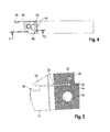
As can further be seen from FIG. 5 , the angle between the top side of the shank 12 and the segments of the rear side 30 is 90° here. However, a different angle may also be selected.
The tool holder 10 is provided with a coolant supply passage having a clamping finger passage 40, a transverse passage 42, a connecting passage 44 and a shank passage 46. The passages enable a coolant flow to be directed to where the cutting insert 18 is machining a workpiece.
The clamping finger passage 40 extends from a forward segment of the clamping finger 28 as far as into the clamping segment 20. There it encounters the transverse passage 42, which extends transversally to the center axis M through the clamping segment 20. Connected to the transverse passage 42 is the connecting passage 44 which extends here in an approximately vertical direction from the clamping passage 20 as far as down to the plane of the shank 12, where it intersects the shank passage 46. The shank passage 46 may either be a short, transversally extending passage, as shown in FIG. 4 , or it may additionally include an extension, which is shown in FIG. 1 and extends as far as to the rear end of the shank. As a result of this, cooling fluid can be supplied either at the front end of the shank or also at the rear end of the shank.
It is an essential feature of the tool holder that the connecting passage 44 is located within the longitudinal center region of the tool holder, thus approximately in the region of the longitudinal center plane. Owing to the special design of the rear side 30 of the clamping segment 20, the connecting passage 44 is thus located within a region of the bending segment in which, when viewed in the longitudinal direction, more material is available than laterally, where the rear side 30 extends more toward the front side of the tool holder.
Therefore, when viewed in a transverse direction, the bending segment 22 has a symmetrical profile of the flexural resistance.
The rear side 30 of the clamping segment 20 does not necessarily need to be executed as three flat segments, as is the case in the illustrated embodiment. It is also possible to design the rear side 30 to be curved, the center point of curvature of the surface of the rear side then being located on the longitudinal center plane, such that a symmetrical profile of the flexural resistance results here as well.
Claims (10)
1. A tool holder for a cutting insert having: a shank, a counter bearing on which a seat for a cutting insert is provided, disposed on the front end of the shank, and a clamping segment integrally joined to the shank via a bending segment;
wherein the clamping segment has a clamping finger and a clamping element, such that the clamping finger is capable of being urged against the counter bearing segment by means of the clamping element, thereby enabling a cutting insert to be clamped between the clamping finger and the counter bearing segment;
wherein the clamping segment projects beyond the top side of the shank;
wherein a coolant supply passage extends through the shank and the bending segment into the clamping segment;
wherein the coolant supply passage has a shank passage, a clamping finger passage and a connecting passage that starts from the shank passage and extends through the bending segment;
characterized in that the connecting passage is located in a longitudinal center region of the tool holder, and—on its rear side facing away from the shank —the clamping segment extends less far in a direction toward the rear end of the shank on both sides of the longitudinal center segment than it does in the longitudinal center segment.
2. The tool holder according to claim 1 , characterized in that the rear side is of curved design and the center of curvature is located on the longitudinal center plane of the shank.
3. The tool holder according to claim 1 , characterized in that the rear side has a center segment and on both sides thereof a side segment, wherein as considered in plan view the side segments extend slightly forward starting from the center segment.
4. The tool holder according to claim 3 , characterized in that each of the side segments is flat.
5. The tool holder according to claim 3 , characterized in that each of the side segments is curved.
6. The tool holder according to claim 3 , characterized in that the center segment is flat.
7. The tool holder according to claim 1 , characterized in that the rear side extends at an angle in a range of 80° to 110° relative to the top side of the shank.
8. The tool holder according to claim 7 , characterized in that the rear side extends at an angle of about 90° relative to the top side of the shank.
9. The tool holder according to claim 1 , characterized in that the connecting passage extends approximately perpendicular to the longitudinal center axis of the shank.
10. The tool holder according claim 1 , characterized in that a transverse passage is provided that connects the connecting passage to the clamping finger passage.
Applications Claiming Priority (3)
| Application Number | Priority Date | Filing Date | Title |
|---|---|---|---|
| DE102014116915.8A DE102014116915A1 (en) | 2014-11-19 | 2014-11-19 | Tool holder for a cutting insert |
| DE102014116915 | 2014-11-19 | ||
| DE102014116915.8 | 2014-11-19 |
Publications (2)
| Publication Number | Publication Date |
|---|---|
| US20160136733A1 US20160136733A1 (en) | 2016-05-19 |
| US9908180B2 true US9908180B2 (en) | 2018-03-06 |
Family
ID=55855097
Family Applications (1)
| Application Number | Title | Priority Date | Filing Date |
|---|---|---|---|
| US14/944,601 Active 2036-07-17 US9908180B2 (en) | 2014-11-19 | 2015-11-18 | Tool holder for a cutting insert |
Country Status (3)
| Country | Link |
|---|---|
| US (1) | US9908180B2 (en) |
| CN (1) | CN105598483B (en) |
| DE (1) | DE102014116915A1 (en) |
Cited By (1)
| Publication number | Priority date | Publication date | Assignee | Title |
|---|---|---|---|---|
| US11904393B1 (en) | 2022-08-18 | 2024-02-20 | Iscar, Ltd. | External grooving insert holder having upper and lower jaws connected by angled hinge portion with cooling channel extending through hinge portion, and cutting tool |
Families Citing this family (11)
| Publication number | Priority date | Publication date | Assignee | Title |
|---|---|---|---|---|
| JP6300737B2 (en) * | 2012-03-06 | 2018-03-28 | イスカル リミテッド | Parting blade and blade holder configured to transport pressurized coolant |
| EP3192600B1 (en) * | 2016-01-18 | 2022-03-09 | Sandvik Intellectual Property AB | Metal cutting tool holder comprising fluid passages |
| DE102016109327A1 (en) | 2016-05-20 | 2017-11-23 | Hartmetall-Werkzeugfabrik Paul Horn Gmbh | Holder for a tool for machining, in particular for a long turning tool |
| US10710166B2 (en) * | 2016-08-22 | 2020-07-14 | Kyocera Corporation | Cutting tool holder, cutting tool, and method of manufacturing machined product using them |
| JP6920811B2 (en) * | 2016-11-30 | 2021-08-18 | 京セラ株式会社 | Manufacturing method for cutting tool holders, cutting tools and cutting products |
| AT15967U1 (en) * | 2017-05-19 | 2018-10-15 | Ceratizit Austria Gmbh | Clamping block for receiving a piercing blade |
| CN109202109B (en) * | 2017-07-07 | 2020-03-17 | 黄宪仁 | Structure of turning tool rest |
| CN110891719B (en) * | 2017-07-27 | 2022-01-18 | 住友电工硬质合金株式会社 | Cutting tool holder |
| DE102017123786A1 (en) | 2017-10-12 | 2019-04-18 | Hartmetall-Werkzeugfabrik Paul Horn Gmbh | Holder for a grooving tool |
| CN108436120A (en) * | 2018-06-14 | 2018-08-24 | 中原内配集团安徽有限责任公司 | A kind of cylinder sleeve borer |
| WO2023058588A1 (en) * | 2021-10-06 | 2023-04-13 | 京セラ株式会社 | Holder, cutting tool, and method for manufacturing machined workpiece |
Citations (9)
| Publication number | Priority date | Publication date | Assignee | Title |
|---|---|---|---|---|
| JPH07227702A (en) * | 1994-02-22 | 1995-08-29 | Mitsubishi Materials Corp | Tool for grooving |
| US20080131215A1 (en) * | 2006-11-28 | 2008-06-05 | Sandvik Intellectual Property Ab | Tool for chip removing machining and a basic body therefor |
| US20120230780A1 (en) * | 2011-03-07 | 2012-09-13 | Kennametal Inc. | Cutting assembly |
| US20130202372A1 (en) * | 2012-02-02 | 2013-08-08 | Iscar, Ltd. | Tool Holder Having Set Screw for Clamping a Cutting Insert Therein |
| US20140030033A1 (en) * | 2011-03-28 | 2014-01-30 | Ernst Graf Gmbh | Tool for the machining of a workpiece with lateral coolant outlet |
| US20140099168A1 (en) * | 2011-06-14 | 2014-04-10 | Hartmetall-Werkzeugfabrik Paul Horn Gmbh | Holder for a cutting device |
| US20140133924A1 (en) * | 2012-11-13 | 2014-05-15 | Iscar, Ltd. | Cutting Tool Holder with Internal Coolant Passage Having a Compressible Member |
| US20140321926A1 (en) * | 2013-04-24 | 2014-10-30 | Iscar, Ltd. | Tool Holder Having A Clamping Member With A Non-Circular Cross-Section And Method For Clamping A Cutting Insert Therein |
| US20140356082A1 (en) * | 2013-05-31 | 2014-12-04 | Ntm, Inc. | Tool holder for machine tool, machine tool assembly, and methods |
Family Cites Families (4)
| Publication number | Priority date | Publication date | Assignee | Title |
|---|---|---|---|---|
| IL191520A (en) * | 2008-05-18 | 2012-04-30 | Iscar Ltd | Cutting tool and cutting insert therefor |
| IL194030A (en) * | 2008-09-11 | 2012-03-29 | Iscar Ltd | Cutting tool and cutting insert therefor |
| US8827598B2 (en) * | 2011-11-22 | 2014-09-09 | Kennametal Inc. | Cutting assembly with enhanced coolant delivery |
| DE102012004804C5 (en) * | 2012-03-09 | 2019-03-14 | Kennametal Inc. | Puncture cutting plate and lancing cutting tool |
-
2014
- 2014-11-19 DE DE102014116915.8A patent/DE102014116915A1/en active Pending
-
2015
- 2015-11-18 CN CN201510794355.7A patent/CN105598483B/en active Active
- 2015-11-18 US US14/944,601 patent/US9908180B2/en active Active
Patent Citations (9)
| Publication number | Priority date | Publication date | Assignee | Title |
|---|---|---|---|---|
| JPH07227702A (en) * | 1994-02-22 | 1995-08-29 | Mitsubishi Materials Corp | Tool for grooving |
| US20080131215A1 (en) * | 2006-11-28 | 2008-06-05 | Sandvik Intellectual Property Ab | Tool for chip removing machining and a basic body therefor |
| US20120230780A1 (en) * | 2011-03-07 | 2012-09-13 | Kennametal Inc. | Cutting assembly |
| US20140030033A1 (en) * | 2011-03-28 | 2014-01-30 | Ernst Graf Gmbh | Tool for the machining of a workpiece with lateral coolant outlet |
| US20140099168A1 (en) * | 2011-06-14 | 2014-04-10 | Hartmetall-Werkzeugfabrik Paul Horn Gmbh | Holder for a cutting device |
| US20130202372A1 (en) * | 2012-02-02 | 2013-08-08 | Iscar, Ltd. | Tool Holder Having Set Screw for Clamping a Cutting Insert Therein |
| US20140133924A1 (en) * | 2012-11-13 | 2014-05-15 | Iscar, Ltd. | Cutting Tool Holder with Internal Coolant Passage Having a Compressible Member |
| US20140321926A1 (en) * | 2013-04-24 | 2014-10-30 | Iscar, Ltd. | Tool Holder Having A Clamping Member With A Non-Circular Cross-Section And Method For Clamping A Cutting Insert Therein |
| US20140356082A1 (en) * | 2013-05-31 | 2014-12-04 | Ntm, Inc. | Tool holder for machine tool, machine tool assembly, and methods |
Cited By (2)
| Publication number | Priority date | Publication date | Assignee | Title |
|---|---|---|---|---|
| US11904393B1 (en) | 2022-08-18 | 2024-02-20 | Iscar, Ltd. | External grooving insert holder having upper and lower jaws connected by angled hinge portion with cooling channel extending through hinge portion, and cutting tool |
| WO2024038425A1 (en) | 2022-08-18 | 2024-02-22 | Iscar Ltd. | Elongated insert holder and cutting tool |
Also Published As
| Publication number | Publication date |
|---|---|
| US20160136733A1 (en) | 2016-05-19 |
| CN105598483A (en) | 2016-05-25 |
| CN105598483B (en) | 2019-05-10 |
| DE102014116915A1 (en) | 2016-05-19 |
Similar Documents
| Publication | Publication Date | Title |
|---|---|---|
| US9908180B2 (en) | Tool holder for a cutting insert | |
| US10029313B2 (en) | Tool holder for a cutting insert and process for manufacturing the tool holder | |
| US20110255926A1 (en) | Cutting Tool and Cutting Insert Therefor | |
| US7887266B2 (en) | Cutting tool and cutting insert therefor | |
| US8529166B2 (en) | Cutting tool and cutting insert therefor | |
| KR20110018312A (en) | Cutting tool and cutting insert therefor | |
| US9314851B2 (en) | Cutting insert having a rearwardly offset cutting edge and cutting tool | |
| KR20120043746A (en) | Cutting insert and rotary cutting tool | |
| US10207329B2 (en) | Toolholder with clamp having fluid flow passages, and tool including such a toolholder | |
| US9827614B2 (en) | Cutting tool assembly having clamp assembly comprising a clamp and a coolant plate | |
| RU2711279C2 (en) | Cutting tool and indexable cutting insert of triangular shape therefor | |
| JP6203842B2 (en) | Cutting tool and cutting insert having a stopper surface | |
| EP2979801B1 (en) | Cutting insert and face milling cutter using same | |
| US3934320A (en) | Grooving and cut off tool | |
| US20150117971A1 (en) | Indexable Asymmetric Cutting Insert and Cutting Tool Therefor | |
| US20150196959A1 (en) | Cutting tool with wedge clamping system | |
| US8813617B2 (en) | Cutting insert and cutting tool | |
| US10010953B2 (en) | Wedge clamp and insert cartridge for cutting tool | |
| CN108602132B (en) | Metal grooving blade for face grooving | |
| JPWO2013031457A1 (en) | Holder and cutting tool | |
| KR102464805B1 (en) | Cutting insert with split cutting edge with leading and trailing part cutting edges | |
| SE1450032A1 (en) | Tool holder and cutting insert for the same | |
| TW201811467A (en) | Cutting tool having an indexable cutting insert retained by a moment force about a pivot axis | |
| US10493539B2 (en) | Tool body having an inner insert receiving pocket with resilient clamping member, cutting tool and chamfering cutting insert therefor | |
| CN105562739A (en) | Hard-alloy turning tool |
Legal Events
| Date | Code | Title | Description |
|---|---|---|---|
| AS | Assignment |
Owner name: KENNAMETAL INC., PENNSYLVANIA Free format text: ASSIGNMENT OF ASSIGNORS INTEREST;ASSIGNORS:KAUFMANN, IGOR;ABDUL, ANWAR MOHIDEEN;REEL/FRAME:037071/0929 Effective date: 20151112 |
|
| STCF | Information on status: patent grant |
Free format text: PATENTED CASE |
|
| MAFP | Maintenance fee payment |
Free format text: PAYMENT OF MAINTENANCE FEE, 4TH YEAR, LARGE ENTITY (ORIGINAL EVENT CODE: M1551); ENTITY STATUS OF PATENT OWNER: LARGE ENTITY Year of fee payment: 4 |