US9903190B2 - Modular fracturing system - Google Patents
Modular fracturing system Download PDFInfo
- Publication number
- US9903190B2 US9903190B2 US14/525,180 US201414525180A US9903190B2 US 9903190 B2 US9903190 B2 US 9903190B2 US 201414525180 A US201414525180 A US 201414525180A US 9903190 B2 US9903190 B2 US 9903190B2
- Authority
- US
- United States
- Prior art keywords
- fracturing
- manifold
- fluid
- skid
- coupled
- Prior art date
- Legal status (The legal status is an assumption and is not a legal conclusion. Google has not performed a legal analysis and makes no representation as to the accuracy of the status listed.)
- Active, expires
Links
- 239000012530 fluid Substances 0.000 claims abstract description 143
- 238000004891 communication Methods 0.000 claims abstract 4
- 230000000712 assembly Effects 0.000 claims description 77
- 238000000429 assembly Methods 0.000 claims description 77
- 238000000034 method Methods 0.000 claims description 10
- 230000008878 coupling Effects 0.000 claims description 7
- 238000010168 coupling process Methods 0.000 claims description 7
- 238000005859 coupling reaction Methods 0.000 claims description 7
- 238000005086 pumping Methods 0.000 claims 2
- VNWKTOKETHGBQD-UHFFFAOYSA-N methane Chemical compound C VNWKTOKETHGBQD-UHFFFAOYSA-N 0.000 description 6
- 238000013461 design Methods 0.000 description 5
- 230000015572 biosynthetic process Effects 0.000 description 4
- 238000005755 formation reaction Methods 0.000 description 4
- 238000004519 manufacturing process Methods 0.000 description 4
- 238000010586 diagram Methods 0.000 description 3
- 238000000605 extraction Methods 0.000 description 3
- 239000003345 natural gas Substances 0.000 description 3
- 230000008901 benefit Effects 0.000 description 2
- 238000005553 drilling Methods 0.000 description 2
- 238000012986 modification Methods 0.000 description 2
- 230000004048 modification Effects 0.000 description 2
- 239000011435 rock Substances 0.000 description 2
- 238000009826 distribution Methods 0.000 description 1
- 210000002310 elbow joint Anatomy 0.000 description 1
- 239000007789 gas Substances 0.000 description 1
- 238000009434 installation Methods 0.000 description 1
- 239000000203 mixture Substances 0.000 description 1
- 238000011084 recovery Methods 0.000 description 1
- 239000004576 sand Substances 0.000 description 1
- 238000005303 weighing Methods 0.000 description 1
Images


Classifications
-
- E—FIXED CONSTRUCTIONS
- E21—EARTH DRILLING; MINING
- E21B—EARTH DRILLING, e.g. DEEP DRILLING; OBTAINING OIL, GAS, WATER, SOLUBLE OR MELTABLE MATERIALS OR A SLURRY OF MINERALS FROM WELLS
- E21B43/00—Methods or apparatus for obtaining oil, gas, water, soluble or meltable materials or a slurry of minerals from wells
- E21B43/25—Methods for stimulating production
- E21B43/26—Methods for stimulating production by forming crevices or fractures
- E21B43/2607—Surface equipment specially adapted for fracturing operations
-
- E—FIXED CONSTRUCTIONS
- E21—EARTH DRILLING; MINING
- E21B—EARTH DRILLING, e.g. DEEP DRILLING; OBTAINING OIL, GAS, WATER, SOLUBLE OR MELTABLE MATERIALS OR A SLURRY OF MINERALS FROM WELLS
- E21B43/00—Methods or apparatus for obtaining oil, gas, water, soluble or meltable materials or a slurry of minerals from wells
- E21B43/25—Methods for stimulating production
- E21B43/26—Methods for stimulating production by forming crevices or fractures
Definitions
- drilling and production systems are often employed to access and extract the resource.
- These systems may be located onshore or offshore depending on the location of a desired resource.
- wellhead assemblies may include a wide variety of components, such as various casings, valves, fluid conduits, and the like, that control drilling or extraction operations.
- such wellhead assemblies may use fracturing trees and other components to facilitate a fracturing process and enhance production from wells.
- resources such as oil and natural gas are generally extracted from fissures or other cavities formed in various subterranean rock formations or strata.
- a well may be subjected to a fracturing process that creates one or more man-made fractures in a rock formation. This facilitates, for example, coupling of pre-existing fissures and cavities, allowing oil, gas, or the like to flow into the wellbore.
- Such fracturing processes typically include injecting a fracturing fluid—which is often a mixture including sand and water—into the well to increase the well's pressure and form the man-made fractures.
- a fracturing manifold may provide fracturing fluid to wells through lines (e.g., pipes) coupled to fracturing trees of wellhead assemblies.
- a fracturing system includes dedicated skid assemblies each coupled to provide fracturing fluid to a single wellhead assembly from a shared fracturing manifold.
- Each of the dedicated skid assemblies can have a single fluid outlet that is coupled to a fracturing tree of its wellhead assembly via a single fluid conduit.
- the skid assemblies are coupled to an additional manifold for providing an additional fluid to the wellhead assemblies via the single fluid outlet of each skid assembly.
- FIG. 1 generally depicts a fracturing system in accordance with an embodiment of the present disclosure
- FIG. 2 is a block diagram of the fracturing system of FIG. 1 with a fracturing manifold coupled to multiple fracturing trees in accordance with one embodiment;
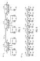
- FIG. 3 is a block diagram of a fracturing system having skid assemblies with multiple fluid outlets for routing fracturing fluid to wellhead assemblies in accordance with one embodiment
- FIG. 4 is a block diagram of a modular fracturing system with skid assemblies each having only a single fluid outlet for routing fracturing fluid to just one wellhead assembly in accordance with one embodiment
- FIGS. 5 and 6 are plan views of fracturing systems with skid assemblies each coupled by a single fluid conduit to a respective fracturing tree of a wellhead assembly in accordance with certain embodiments.
- FIGS. 7 and 8 are perspective views showing additional details of one of the skid assemblies depicted in FIGS. 5 and 6 in accordance with one embodiment.
- the articles “a,” “an,” “the,” and “said” are intended to mean that there are one or more of the elements.
- the terms “comprising,” “including,” and “having” are intended to be inclusive and mean that there may be additional elements other than the listed elements.
- any use of “top,” “bottom,” “above,” “below,” other directional terms, and variations of these terms is made for convenience, but does not require any particular orientation of the components.
- the fracturing system 10 facilitates extraction of natural resources (e.g., oil or natural gas) from a reservoir 12 via a well 14 and a wellhead 16 . Particularly, by injecting a fracturing fluid down the well 14 into the reservoir 12 , the fracturing system 10 increases the number or size of fractures in a formation to enhance recovery of natural resources present in the formation.
- the well 14 is a surface well accessed through equipment of wellhead 16 installed at surface level (i.e., on ground 18 ). But it will be appreciated that natural resources may be extracted from other wells, such as platform or subsea wells.
- the fracturing system 10 includes various components to control flow of a fracturing fluid into the well 14 .
- the depicted fracturing system 10 includes a fracturing tree 20 and a fracturing manifold system 22 .
- the fracturing tree 20 is coupled to the wellhead 16 and can be considered part of a wellhead assembly, which includes the wellhead 16 and other coupled components.
- the fracturing tree 20 can be mounted above the wellhead 16 or can be a horizontal fracturing tree connected to a side of the wellhead 16 .
- the fracturing tree 20 can include at least one valve that controls flow of the fracturing fluid into the wellhead 16 and, subsequently, down the well 14 to the reservoir 12 .
- the fracturing manifold system 22 can include at least one valve that controls flow of the fracturing fluid to the fracturing tree 20 by a conduit or fluid connection 26 (e.g., pipes).
- the fracturing manifold system 22 is connected to provide fracturing fluid to multiple fracturing trees 20 and wellheads 16 . But it is noted that the fracturing manifold system 22 may instead be coupled to a single fracturing tree 20 in full accordance with the present techniques. As discussed in greater detail below, various components of the fracturing manifold system 22 can be mounted on skids to facilitate movement of the fracturing manifold system 22 with respect to the ground 18 and installation of the system 22 at a wellsite.
- Fracturing fluid from a supply 28 is provided to the fracturing manifold system 22 .
- a connector 30 receives fracturing fluid from the supply 28 through a conduit or fluid connection 32 (e.g., pipes or hoses) and then transmits the fluid to the fracturing manifold system 22 by way of a subterranean conduit or fluid connection 34 (e.g., pipes).
- the fluid connection 34 could be provided above the ground 18 in other instances.
- the fracturing fluid supply 28 is provided by one or more trucks that deliver the fracturing fluid, connect to the connector 30 , and pump the fluid into the fracturing manifold system 22 via the connector 30 and connections 32 and 34 .
- the fracturing fluid supply 28 is in the form of a reservoir from which fluid may be pumped into the fracturing manifold system 22 .
- any other suitable sources of fracturing fluid and manners for transmitting such fluid to the fracturing manifold system may instead be used.
- the fracturing manifold system 40 includes a fracturing manifold line 42 coupled to skid apparatuses or assemblies 44 .
- Fracturing fluid pumped through the fracturing manifold line 42 to the skid apparatuses 44 can be routed from fracturing fluid outlets 46 of the skid apparatuses 44 to the wellhead assemblies 50 through fluid conduits 52 , which can be coupled to fracturing trees of the wellhead assemblies 50 .
- each wellhead assembly 50 is coupled to receive fracturing fluid from a single (i.e., only one) skid apparatus 44 by a single fluid conduit 52 .
- multiple fluid conduits 52 could be used to couple a wellhead assembly 50 to receive fracturing fluid from one or more skid apparatuses 44 .
- Each of the skid apparatuses 44 is depicted in FIG. 3 as having four outlets 46 , allowing the skid apparatus 44 to be connected to four different wellhead assemblies 50 .
- the skid apparatuses 44 could include a different number of outlets 46 , such as two or three.
- the skid apparatuses 44 could have different numbers of fracturing fluid outlets 46 , such as some skid apparatuses 44 having two fracturing fluid outlets 46 and others having four fracturing fluid outlets 46 . Having multiple fracturing fluid outlets 46 on the skid apparatuses 44 facilitates connection of a skid apparatus 44 to multiple wellhead assemblies 50 and may reduce the number of skid apparatuses 44 needed at a particular wellsite.
- a fracturing manifold system 60 includes a fracturing manifold line 62 coupled to skid assemblies or apparatuses 64 .
- the fracturing manifold line 62 like the fracturing manifold line 42 , can include various pipes and connection blocks to enable distribution of fracturing fluid to the connected skid apparatuses.
- Fracturing fluid received by the skid apparatuses 64 can be routed via fracturing fluid outlets 66 to wellhead assemblies 50 via fluid conduits 68 .
- each skid apparatus 64 includes a single fracturing fluid outlet 66 , which is coupled to a single wellhead assembly 50 by a single fluid conduit 68 .
- each wellhead assembly 50 can be said to have its own dedicated skid apparatus 64 and the ratio of wellhead assemblies 50 to skid apparatuses 64 is one to one.
- this modular arrangement allows each dedicated skid apparatus 64 to be positioned directly in front of its respective wellhead assembly 50 (e.g., in front of a horizontal fracturing tree).
- the fracturing manifold system 60 in other embodiments could include skid apparatuses with different numbers of fluid outlets for connection to varying numbers of wellhead assemblies, such as some skid apparatuses each having a single fluid outlet for connection to a single wellhead assembly and other skid apparatuses each having multiple fluid outlets for connection to multiple wellhead assemblies.
- fracturing manifold systems 70 FIG. 5
- a fracturing manifold system 100 FIG. 6
- each skid assembly 74 is connected by fluid lines or conduits 76 to fracturing trees 78 of the wellhead assemblies 50 , with a one-to-one ratio of skid assemblies 74 to fracturing trees 78 .
- Each skid assembly 74 includes a single fracturing fluid outlet that is connected to one respective fracturing tree 78 by a single fluid conduit 76 .
- the fluid conduits 76 include pipes and elbow joints to facilitate connection between the skid assemblies 74 and the fracturing trees 78 . But the fluid conduits 76 may be provided in different forms in other embodiments.
- Fracturing fluid can be supplied to the fracturing fluid manifold 72 through an inlet 80 .
- the fracturing fluid manifold 72 includes a series of pipes connected between connection blocks coupled to and supported on the skid assemblies 74 .
- the connection blocks of the fracturing fluid manifold 72 could be set back from the skid assemblies 74 .
- the depicted fracturing fluid manifold 72 also includes a splitter 82 with valves for controlling flow of fracturing fluid into branch lines 84 and 86 to the left and right of the splitter 82 .
- the splitter 82 is shown here as a two-way splitter for routing fracturing fluid to the two branch lines 84 and 86 , in other embodiments the splitter 82 could be connected to more than two branch lines.
- the splitter 82 can be operated to provide fracturing fluid to either or both of the branch lines 84 and 86 , and valves of the skid assemblies 74 can be operated to supply fracturing fluid from the branch lines to the wellhead assemblies 50 .
- the branch lines 84 and 86 are each coupled to the same number of skid assemblies 74
- the branch lines 84 and 86 are coupled to a different number of skid assemblies 74 .
- an additional manifold can be coupled to the skid assemblies of the fracturing system.
- an additional manifold 90 is coupled to the skid assemblies 74 .
- the additional manifold 90 is a pump-down manifold for routing fluid to wellhead assemblies 50 to pump a downhole tool (e.g., a wireline tool having a plug or a perforating gun) down the wells.
- the additional manifold 90 is depicted as including a fluid inlet 92 and a splitter 94 for controlling flow of fluid into branch lines 96 and 98 coupled to the skid assemblies 74 .
- each of the skid assemblies 74 has separate inlets connected to the fracturing fluid manifold and the additional manifold, but has a single, common outlet for supplying fluids from the multiple manifolds to a connected wellhead assembly 50 via a single fluid conduit 76 .
- the ability to provide fluid from the additional manifold through the same skid assemblies and out to the wellhead assemblies via the same outlets and fluid conduits used to convey the fracturing fluid to the wellhead assemblies can eliminate the need for separate, additional fluid connections to the wellhead assemblies to provide such fluid.
- the depicted skid assembly 74 includes a flow control assembly having various components mounted on a skid 104 .
- a connection block 106 of the fracturing manifold 72 is supported on the skid 104 and can be connected to connection blocks of other skid assemblies 74 via manifold pipes 108 .
- the manifold pipes 108 have a diameter equal to that of the fluid conduit 76 (e.g., five and one-eighth inches).
- the connection block 106 is coupled to an inlet 110 of the skid assembly 74 .
- a valve 112 and a connection block 114 having an outlet 116 is also mounted on the skid 104 .
- the valve 112 can be opened and closed to control flow of fracturing fluid (from the fracturing manifold 72 ) between the inlet 110 and the outlet 116 .
- a fluid conduit 76 can be connected to the connection block 114 at the outlet 116 to convey fluid (e.g., fracturing fluid) from the skid assembly 74 to a fracturing tree 78 of a wellhead assembly 50 , such as shown in FIGS. 5 and 6 .
- the additional manifold 90 includes pipes 120 and a connection block 122 for routing an additional fluid through the outlet 116 and the fluid conduit 76 to a wellhead assembly 50 .
- the additional manifold 90 is connected to an inlet 124 of a connection block 126 of the skid assembly 74 .
- a valve 128 between the connection block 126 and the connection block 114 can be opened and closed to control flow of the additional fluid between the inlet 124 and the outlet 116 .
- the skid assembly 74 includes multiple inlets for receiving fluids, but only a single, shared outlet 116 (common to both inlet 110 and inlet 124 ) for routing the fluids received from the manifolds 72 and 90 to a wellhead assembly 50 through a fluid conduit 76 .
- the connection block 126 and the valve 128 can be positioned at an angle (e.g., thirty degrees) with respect to a horizontal plane through the fracturing manifold 72 , the connection 106 , and the valve 112 .
- the additional fluid from the manifold 90 can be used to pump a downhole tool (e.g., a tool for plugging and perforating a casing in the well) to a desired position in a well.
- a downhole tool e.g., a tool for plugging and perforating a casing in the well
- this includes operating the valve 128 to allow fluid from a pump-down manifold 90 to pass through the valve 128 , out of the skid assembly 74 through the outlet 116 , and into a well (in which the tool is disposed) through a single fluid line 76 and the wellhead assembly 50 .
- the well can then be fractured by operating the valve 112 to route fracturing fluid through the outlet 116 , the single fluid line 76 , and the wellhead assembly 50 .
- the fracturing manifold 72 is a five and one-eighth inch manifold with a 15,000 psi rating
- the additional manifold 90 is a three and one-sixteenth inch manifold with a 10,000 psi rating. But other configurations could instead be used.
- the skid assembly 74 is a compact skid assembly weighing less than five thousand pounds and having dimensions of less than fifty inches by seventy inches by fifty inches having a bore through the valve 112 and connection block 114 having a diameter of five and one-eighth inch and a 15,000 psi rating.
- the compact size and single-outlet design allows each skid assembly 74 to be placed closely to its dedicated wellhead assembly, such as within fifteen feet or thirty feet of a fracturing tree of the wellhead assembly. This can reduce the length of pipe runs for connecting the skid assemblies to the fracturing trees.
- the compact size also allows the flow control equipment of the skid assembly to be more easily accessed by operators at ground level, rather than having to climb scaffolding to reach upper portions of taller assemblies.
- skid assemblies with tarps or other covers to protect the assemblies in harsh conditions.
- the use of these compact skid assemblies may reduce the expense of moving, installing, and connecting a fracturing manifold at a wellsite.
- the modular design of certain embodiments is adaptable to various well spacing or configurations, which can further reduce deployment expenses.
Abstract
Description
Claims (20)
Priority Applications (5)
| Application Number | Priority Date | Filing Date | Title |
|---|---|---|---|
| US14/525,180 US9903190B2 (en) | 2014-10-27 | 2014-10-27 | Modular fracturing system |
| CA2966015A CA2966015C (en) | 2014-10-27 | 2015-10-23 | Modular fracturing system |
| PCT/US2015/057057 WO2016069390A1 (en) | 2014-10-27 | 2015-10-23 | Modular fracturing system |
| US15/904,872 US20180291718A1 (en) | 2014-10-27 | 2018-02-26 | Modular fracturing system |
| US17/142,574 US20210372253A1 (en) | 2014-10-27 | 2021-01-06 | Modular fracturing system |
Applications Claiming Priority (1)
| Application Number | Priority Date | Filing Date | Title |
|---|---|---|---|
| US14/525,180 US9903190B2 (en) | 2014-10-27 | 2014-10-27 | Modular fracturing system |
Related Child Applications (1)
| Application Number | Title | Priority Date | Filing Date |
|---|---|---|---|
| US15/904,872 Continuation US20180291718A1 (en) | 2014-10-27 | 2018-02-26 | Modular fracturing system |
Publications (2)
| Publication Number | Publication Date |
|---|---|
| US20160115773A1 US20160115773A1 (en) | 2016-04-28 |
| US9903190B2 true US9903190B2 (en) | 2018-02-27 |
Family
ID=55791586
Family Applications (3)
| Application Number | Title | Priority Date | Filing Date |
|---|---|---|---|
| US14/525,180 Active 2035-09-12 US9903190B2 (en) | 2014-10-27 | 2014-10-27 | Modular fracturing system |
| US15/904,872 Abandoned US20180291718A1 (en) | 2014-10-27 | 2018-02-26 | Modular fracturing system |
| US17/142,574 Abandoned US20210372253A1 (en) | 2014-10-27 | 2021-01-06 | Modular fracturing system |
Family Applications After (2)
| Application Number | Title | Priority Date | Filing Date |
|---|---|---|---|
| US15/904,872 Abandoned US20180291718A1 (en) | 2014-10-27 | 2018-02-26 | Modular fracturing system |
| US17/142,574 Abandoned US20210372253A1 (en) | 2014-10-27 | 2021-01-06 | Modular fracturing system |
Country Status (3)
| Country | Link |
|---|---|
| US (3) | US9903190B2 (en) |
| CA (1) | CA2966015C (en) |
| WO (1) | WO2016069390A1 (en) |
Cited By (44)
| Publication number | Priority date | Publication date | Assignee | Title |
|---|---|---|---|---|
| US20170370172A1 (en) * | 2016-06-23 | 2017-12-28 | Seaboard International, Inc. | Adjustable fracturing system |
| US20180224044A1 (en) * | 2017-02-06 | 2018-08-09 | Mwfc Inc. | Fluid connector for multi-well operations |
| US20180320476A1 (en) * | 2017-05-03 | 2018-11-08 | Ge Oil & Gas Pressure Control Lp | Valve operation and rapid conversion system and method |
| US10309564B1 (en) | 2018-11-08 | 2019-06-04 | Oil States Energy Services, L.L.C. | Extendable spool |
| US10323475B2 (en) | 2015-11-13 | 2019-06-18 | Cameron International Corporation | Fracturing fluid delivery system |
| US10385645B2 (en) | 2011-09-23 | 2019-08-20 | Cameron International Corporation | Fracturing manifold systems and methods |
| US10385662B2 (en) * | 2012-01-11 | 2019-08-20 | Cameron International Corporation | Well fracturing manifold apparatus |
| US10487637B2 (en) | 2011-09-23 | 2019-11-26 | Cameron International Corporation | Adjustable fracturing system |
| US10570692B1 (en) | 2019-06-17 | 2020-02-25 | Oil States Energy Services, L.L.C. | Zipper bridge |
| US10774965B1 (en) | 2017-03-02 | 2020-09-15 | KHOLLE Magnolia 2015, LLC | Flowline component with rotatable flange on retainer segments |
| US10801294B2 (en) | 2018-08-13 | 2020-10-13 | Stream-Flo Industries Ltd. | Adjustable fracturing manifold module, system and method |
| US10858902B2 (en) | 2019-04-24 | 2020-12-08 | Oil States Energy Services, L.L.C. | Frac manifold and connector |
| US10982523B1 (en) | 2017-01-05 | 2021-04-20 | KHOLLE Magnolia 2015, LLC | Frac manifold missile and fitting |
| US10982522B1 (en) * | 2018-07-18 | 2021-04-20 | KHOLLE Magnolia 2015, LLC | Missile for frac manifold |
| US10995561B1 (en) | 2017-03-02 | 2021-05-04 | KHOLLE Magnolia 2015, LLC | Flowline component with threaded rotatable flange |
| US11015413B2 (en) | 2018-10-31 | 2021-05-25 | Cameron International Corporation | Fracturing system with fluid conduit having communication line |
| US11066913B2 (en) | 2016-05-01 | 2021-07-20 | Cameron International Corporation | Flexible fracturing line with removable liner |
| US11091993B2 (en) | 2019-06-17 | 2021-08-17 | Oil States Energy Services, L.L.C. | Zipper bridge |
| US11180979B1 (en) | 2018-11-30 | 2021-11-23 | Quarter Turn Pressure Control, LLC | High pressure jumper manifold |
| US11193349B1 (en) | 2020-03-21 | 2021-12-07 | KHOLLE Magnolia 2015, LLC | Dual path control fitting |
| US11226642B2 (en) * | 2017-04-03 | 2022-01-18 | Fmc Technologies, Inc. | Zipper manifold arrangement for trailer deployment |
| US11248456B2 (en) | 2020-04-03 | 2022-02-15 | Halliburton Energy Services, Inc. | Simultaneous multiple well stimulation |
| US11319757B2 (en) | 2019-12-26 | 2022-05-03 | Cameron International Corporation | Flexible fracturing fluid delivery conduit quick connectors |
| US11384876B2 (en) | 2020-07-07 | 2022-07-12 | Safoco, Inc. | Fluid conduit connector system |
| US11428053B1 (en) | 2019-09-09 | 2022-08-30 | Vault Pressure Control, Llc | System for connecting piping systems for hydraulic fracturing of oil and gas wells |
| US11434737B2 (en) | 2017-12-05 | 2022-09-06 | U.S. Well Services, LLC | High horsepower pumping configuration for an electric hydraulic fracturing system |
| US11451016B2 (en) | 2012-11-16 | 2022-09-20 | U.S. Well Services, LLC | Switchgear load sharing for oil field equipment |
| US11449018B2 (en) | 2012-11-16 | 2022-09-20 | U.S. Well Services, LLC | System and method for parallel power and blackout protection for electric powered hydraulic fracturing |
| US11454170B2 (en) | 2012-11-16 | 2022-09-27 | U.S. Well Services, LLC | Turbine chilling for oil field power generation |
| US11454079B2 (en) | 2018-09-14 | 2022-09-27 | U.S. Well Services Llc | Riser assist for wellsites |
| US11459863B2 (en) | 2019-10-03 | 2022-10-04 | U.S. Well Services, LLC | Electric powered hydraulic fracturing pump system with single electric powered multi-plunger fracturing pump |
| US11476781B2 (en) | 2012-11-16 | 2022-10-18 | U.S. Well Services, LLC | Wireline power supply during electric powered fracturing operations |
| US11506126B2 (en) | 2019-06-10 | 2022-11-22 | U.S. Well Services, LLC | Integrated fuel gas heater for mobile fuel conditioning equipment |
| US11519536B2 (en) | 2020-07-07 | 2022-12-06 | Safoco, Inc. | Fluid conduit connector system |
| US11530601B2 (en) | 2020-07-07 | 2022-12-20 | Safoco, Inc. | Fluid conduit connector system |
| US11578577B2 (en) | 2019-03-20 | 2023-02-14 | U.S. Well Services, LLC | Oversized switchgear trailer for electric hydraulic fracturing |
| US11585197B2 (en) | 2018-11-21 | 2023-02-21 | Halliburton Energy Services, Inc. | Split flow pumping system configuration |
| US11585200B1 (en) | 2021-10-27 | 2023-02-21 | Force Pressure Control, LLC | Systems and methods for control of a multichannel fracturing pump connection |
| US11674352B2 (en) | 2012-11-16 | 2023-06-13 | U.S. Well Services, LLC | Slide out pump stand for hydraulic fracturing equipment |
| US11713661B2 (en) | 2012-11-16 | 2023-08-01 | U.S. Well Services, LLC | Electric powered pump down |
| US11728709B2 (en) | 2019-05-13 | 2023-08-15 | U.S. Well Services, LLC | Encoderless vector control for VFD in hydraulic fracturing applications |
| US11850563B2 (en) | 2012-11-16 | 2023-12-26 | U.S. Well Services, LLC | Independent control of auger and hopper assembly in electric blender system |
| US11879582B2 (en) | 2019-11-14 | 2024-01-23 | Stream-Flo Industries Ltd. | Method and system for fluidly connecting fracturing manifold and fracturing tree |
| US11959533B2 (en) | 2017-12-05 | 2024-04-16 | U.S. Well Services Holdings, Llc | Multi-plunger pumps and associated drive systems |
Families Citing this family (9)
| Publication number | Priority date | Publication date | Assignee | Title |
|---|---|---|---|---|
| US10633934B2 (en) | 2017-01-05 | 2020-04-28 | KHOLLE Magnolia 2015, LLC | Flowline junction fitting with long-sweep bore |
| US10683708B2 (en) * | 2017-01-05 | 2020-06-16 | KHOLLE Magnolia 2015, LLC | Frac manifold and systems |
| US10538973B2 (en) | 2017-01-05 | 2020-01-21 | KHOLLE Magnolia 2015, LLC | Offset flange and angled shim flowline fittings |
| US10563778B2 (en) * | 2018-01-30 | 2020-02-18 | Chevron U.S.A. Inc. | Multi-well fracturing pads using shuttle valves |
| US11753890B2 (en) | 2019-01-15 | 2023-09-12 | Schlumberger Technology Corporation | Real-time pump-down perforating data acquisition and application automation response |
| US11619326B1 (en) | 2019-06-24 | 2023-04-04 | Cantex International, Inc. | Anti-vibration mount |
| US11371330B2 (en) * | 2019-07-24 | 2022-06-28 | Schlumberger Technology Corporation | Coordinated pumping operations |
| CN113027406B (en) * | 2021-04-01 | 2022-07-08 | 建湖县鸿达阀门管件有限公司 | High-sulfur-resistance zipper type fracturing flow-dividing manifold of continuous drilling system |
| CN115075795B (en) * | 2022-07-11 | 2024-03-19 | 山东瑞美油气装备技术创新中心有限公司 | Manifold sledge |
Citations (32)
| Publication number | Priority date | Publication date | Assignee | Title |
|---|---|---|---|---|
| US1615536A (en) | 1923-06-29 | 1927-01-25 | Mar Harry Del | Pipe-joint union |
| US3233668A (en) | 1963-11-15 | 1966-02-08 | Exxon Production Research Co | Recovery of shale oil |
| US4355961A (en) | 1978-04-03 | 1982-10-26 | Ingersoll-Rand Company | Controlling means for a fuel valve |
| US4366864A (en) | 1980-11-24 | 1983-01-04 | Exxon Research And Engineering Co. | Method for recovery of hydrocarbons from oil-bearing limestone or dolomite |
| US4570673A (en) | 1984-10-01 | 1986-02-18 | Halliburton Company | Fluid flow delivery system |
| US4603887A (en) | 1984-10-01 | 1986-08-05 | Halliburton Company | Rigid adjustable length assembly |
| US4767136A (en) | 1986-06-18 | 1988-08-30 | Cogema, Compagnie Generale Des Matieres Nucleaires | Tight coupling device for two rigid, fixed pipes |
| CA2178856A1 (en) | 1996-06-12 | 1997-12-13 | L. Murray Dallas | Blowout Preventer Protector and Method of Using Same During Oil and Gas Well Stimulation |
| US6234030B1 (en) | 1998-08-28 | 2001-05-22 | Rosewood Equipment Company | Multiphase metering method for multiphase flow |
| US6364024B1 (en) | 2000-01-28 | 2002-04-02 | L. Murray Dallas | Blowout preventer protector and method of using same |
| US20030205385A1 (en) | 2002-02-19 | 2003-11-06 | Duhn Rex E. | Connections for wellhead equipment |
| US20030205378A1 (en) | 2001-10-24 | 2003-11-06 | Wellington Scott Lee | In situ recovery from lean and rich zones in a hydrocarbon containing formation |
| US20040251020A1 (en) | 2001-09-07 | 2004-12-16 | Smith David Randolph | Adjustable well screen assembly |
| US20080277120A1 (en) | 2007-05-11 | 2008-11-13 | Stinger Wellhead Protection, Inc. | Retrievable frac mandrel and well control stack to facilitate well completion, re-completion or workover and method of use |
| US20090261575A1 (en) | 2008-04-22 | 2009-10-22 | Halliburton Energy Services Inc. | Adjustable Length Discharge Joint for High Pressure Applications |
| US20100051261A1 (en) | 2008-03-03 | 2010-03-04 | T-3 Property Holdings, Inc. | Telescopic fracturing isolation sleeve |
| US20100300672A1 (en) | 2009-05-27 | 2010-12-02 | Childress Everett L | Time and efficiency manifold |
| US20110108275A1 (en) | 2009-11-12 | 2011-05-12 | Vetco Gray Inc. | Wellhead isolation protection sleeve |
| US20110114320A1 (en) | 2009-07-31 | 2011-05-19 | Schlumberger Technology Corporation | Stand-alone frac liner system |
| US20110132596A1 (en) | 2006-11-15 | 2011-06-09 | Yeh Charles S | Wellbore Method and Apparatus For Completion, Production and Injection |
| US20110259584A1 (en) | 2010-04-26 | 2011-10-27 | Broussard Ii Wayne F | Fractionation system and methods of using same |
| US20120181016A1 (en) | 2009-08-04 | 2012-07-19 | T-3 Property Holdings, Inc. | Collection block with multi-directional flow inlets in oilfield applications |
| US20120181030A1 (en) | 2011-01-13 | 2012-07-19 | T-3 Property Holdings, Inc. | Goat head type injection block for fracturing trees in oilfield applications |
| US20120181015A1 (en) * | 2011-01-13 | 2012-07-19 | T-3 Property Holdings, Inc. | Uni-bore dump line for fracturing manifold |
| US20130076026A1 (en) | 2011-09-23 | 2013-03-28 | Cameron International Corporation | Adjustable fracturing head and manifold system |
| US20130075080A1 (en) * | 2011-09-23 | 2013-03-28 | Cameron International Corporation | Adjustable fracturing system |
| US20130175038A1 (en) | 2012-01-11 | 2013-07-11 | Cameron International Corporation | Integral fracturing manifold |
| US20130284455A1 (en) | 2012-04-26 | 2013-10-31 | Ge Oil & Gas Pressure Control Lp | Delivery System for Fracture Applications |
| US20140238683A1 (en) | 2013-02-27 | 2014-08-28 | Nabors Alaska Drilling, Inc. | Integrated Arctic Fracking Apparatus and Methods |
| US8905056B2 (en) | 2010-09-15 | 2014-12-09 | Halliburton Energy Services, Inc. | Systems and methods for routing pressurized fluid |
| US9068450B2 (en) | 2011-09-23 | 2015-06-30 | Cameron International Corporation | Adjustable fracturing system |
| US20150354313A1 (en) * | 2014-06-04 | 2015-12-10 | McClinton Energy Group, LLC | Decomposable extended-reach frac plug, decomposable slip, and methods of using same |
-
2014
- 2014-10-27 US US14/525,180 patent/US9903190B2/en active Active
-
2015
- 2015-10-23 CA CA2966015A patent/CA2966015C/en active Active
- 2015-10-23 WO PCT/US2015/057057 patent/WO2016069390A1/en active Application Filing
-
2018
- 2018-02-26 US US15/904,872 patent/US20180291718A1/en not_active Abandoned
-
2021
- 2021-01-06 US US17/142,574 patent/US20210372253A1/en not_active Abandoned
Patent Citations (39)
| Publication number | Priority date | Publication date | Assignee | Title |
|---|---|---|---|---|
| US1615536A (en) | 1923-06-29 | 1927-01-25 | Mar Harry Del | Pipe-joint union |
| US3233668A (en) | 1963-11-15 | 1966-02-08 | Exxon Production Research Co | Recovery of shale oil |
| US4355961A (en) | 1978-04-03 | 1982-10-26 | Ingersoll-Rand Company | Controlling means for a fuel valve |
| US4366864A (en) | 1980-11-24 | 1983-01-04 | Exxon Research And Engineering Co. | Method for recovery of hydrocarbons from oil-bearing limestone or dolomite |
| US4570673A (en) | 1984-10-01 | 1986-02-18 | Halliburton Company | Fluid flow delivery system |
| US4603887A (en) | 1984-10-01 | 1986-08-05 | Halliburton Company | Rigid adjustable length assembly |
| US4767136A (en) | 1986-06-18 | 1988-08-30 | Cogema, Compagnie Generale Des Matieres Nucleaires | Tight coupling device for two rigid, fixed pipes |
| CA2178856A1 (en) | 1996-06-12 | 1997-12-13 | L. Murray Dallas | Blowout Preventer Protector and Method of Using Same During Oil and Gas Well Stimulation |
| US6234030B1 (en) | 1998-08-28 | 2001-05-22 | Rosewood Equipment Company | Multiphase metering method for multiphase flow |
| US6364024B1 (en) | 2000-01-28 | 2002-04-02 | L. Murray Dallas | Blowout preventer protector and method of using same |
| US20040251020A1 (en) | 2001-09-07 | 2004-12-16 | Smith David Randolph | Adjustable well screen assembly |
| US20030205378A1 (en) | 2001-10-24 | 2003-11-06 | Wellington Scott Lee | In situ recovery from lean and rich zones in a hydrocarbon containing formation |
| US20030205385A1 (en) | 2002-02-19 | 2003-11-06 | Duhn Rex E. | Connections for wellhead equipment |
| US20110132596A1 (en) | 2006-11-15 | 2011-06-09 | Yeh Charles S | Wellbore Method and Apparatus For Completion, Production and Injection |
| US20080277120A1 (en) | 2007-05-11 | 2008-11-13 | Stinger Wellhead Protection, Inc. | Retrievable frac mandrel and well control stack to facilitate well completion, re-completion or workover and method of use |
| US20100051261A1 (en) | 2008-03-03 | 2010-03-04 | T-3 Property Holdings, Inc. | Telescopic fracturing isolation sleeve |
| US20090261575A1 (en) | 2008-04-22 | 2009-10-22 | Halliburton Energy Services Inc. | Adjustable Length Discharge Joint for High Pressure Applications |
| US20100300672A1 (en) | 2009-05-27 | 2010-12-02 | Childress Everett L | Time and efficiency manifold |
| US20110114320A1 (en) | 2009-07-31 | 2011-05-19 | Schlumberger Technology Corporation | Stand-alone frac liner system |
| US20120181016A1 (en) | 2009-08-04 | 2012-07-19 | T-3 Property Holdings, Inc. | Collection block with multi-directional flow inlets in oilfield applications |
| US20110108275A1 (en) | 2009-11-12 | 2011-05-12 | Vetco Gray Inc. | Wellhead isolation protection sleeve |
| US20110259584A1 (en) | 2010-04-26 | 2011-10-27 | Broussard Ii Wayne F | Fractionation system and methods of using same |
| US8905056B2 (en) | 2010-09-15 | 2014-12-09 | Halliburton Energy Services, Inc. | Systems and methods for routing pressurized fluid |
| US20120181030A1 (en) | 2011-01-13 | 2012-07-19 | T-3 Property Holdings, Inc. | Goat head type injection block for fracturing trees in oilfield applications |
| US20120181015A1 (en) * | 2011-01-13 | 2012-07-19 | T-3 Property Holdings, Inc. | Uni-bore dump line for fracturing manifold |
| US20140246211A1 (en) | 2011-09-23 | 2014-09-04 | Cameron International Corporation | Adjustable fracturing system |
| US8978763B2 (en) | 2011-09-23 | 2015-03-17 | Cameron International Corporation | Adjustable fracturing system |
| US20160024857A1 (en) | 2011-09-23 | 2016-01-28 | Cameron International Corporation | Adjustable fracturing system |
| US9068450B2 (en) | 2011-09-23 | 2015-06-30 | Cameron International Corporation | Adjustable fracturing system |
| US20130075080A1 (en) * | 2011-09-23 | 2013-03-28 | Cameron International Corporation | Adjustable fracturing system |
| US20130076026A1 (en) | 2011-09-23 | 2013-03-28 | Cameron International Corporation | Adjustable fracturing head and manifold system |
| US8839867B2 (en) | 2012-01-11 | 2014-09-23 | Cameron International Corporation | Integral fracturing manifold |
| US20130175038A1 (en) | 2012-01-11 | 2013-07-11 | Cameron International Corporation | Integral fracturing manifold |
| US9222345B2 (en) | 2012-01-11 | 2015-12-29 | Cameron International Corporation | Well fracturing systems and methods |
| US9255469B2 (en) | 2012-01-11 | 2016-02-09 | Cameron International Corporation | Integral fracturing manifold |
| US9127545B2 (en) | 2012-04-26 | 2015-09-08 | Ge Oil & Gas Pressure Control Lp | Delivery system for fracture applications |
| US20130284455A1 (en) | 2012-04-26 | 2013-10-31 | Ge Oil & Gas Pressure Control Lp | Delivery System for Fracture Applications |
| US20140238683A1 (en) | 2013-02-27 | 2014-08-28 | Nabors Alaska Drilling, Inc. | Integrated Arctic Fracking Apparatus and Methods |
| US20150354313A1 (en) * | 2014-06-04 | 2015-12-10 | McClinton Energy Group, LLC | Decomposable extended-reach frac plug, decomposable slip, and methods of using same |
Cited By (70)
| Publication number | Priority date | Publication date | Assignee | Title |
|---|---|---|---|---|
| US10385643B2 (en) | 2011-09-23 | 2019-08-20 | Cameron International Corporation | Fracturing manifold systems and methods |
| US11391109B2 (en) | 2011-09-23 | 2022-07-19 | Cameron International Corporation | Fracturing manifold systems and methods |
| US10876371B2 (en) | 2011-09-23 | 2020-12-29 | Cameron International Corporation | Fracturing manifold system |
| US10487637B2 (en) | 2011-09-23 | 2019-11-26 | Cameron International Corporation | Adjustable fracturing system |
| US10385645B2 (en) | 2011-09-23 | 2019-08-20 | Cameron International Corporation | Fracturing manifold systems and methods |
| US10934816B2 (en) | 2012-01-11 | 2021-03-02 | Cameron International Corporation | Well fracturing manifold apparatus |
| US11536119B2 (en) | 2012-01-11 | 2022-12-27 | Cameron International Corporation | Well fracturing manifold apparatus |
| US10385662B2 (en) * | 2012-01-11 | 2019-08-20 | Cameron International Corporation | Well fracturing manifold apparatus |
| US11449018B2 (en) | 2012-11-16 | 2022-09-20 | U.S. Well Services, LLC | System and method for parallel power and blackout protection for electric powered hydraulic fracturing |
| US11850563B2 (en) | 2012-11-16 | 2023-12-26 | U.S. Well Services, LLC | Independent control of auger and hopper assembly in electric blender system |
| US11476781B2 (en) | 2012-11-16 | 2022-10-18 | U.S. Well Services, LLC | Wireline power supply during electric powered fracturing operations |
| US11454170B2 (en) | 2012-11-16 | 2022-09-27 | U.S. Well Services, LLC | Turbine chilling for oil field power generation |
| US11674352B2 (en) | 2012-11-16 | 2023-06-13 | U.S. Well Services, LLC | Slide out pump stand for hydraulic fracturing equipment |
| US11451016B2 (en) | 2012-11-16 | 2022-09-20 | U.S. Well Services, LLC | Switchgear load sharing for oil field equipment |
| US11713661B2 (en) | 2012-11-16 | 2023-08-01 | U.S. Well Services, LLC | Electric powered pump down |
| US11598174B2 (en) | 2015-11-13 | 2023-03-07 | Cameron International Corporation | Fracturing fluid delivery system |
| US10323475B2 (en) | 2015-11-13 | 2019-06-18 | Cameron International Corporation | Fracturing fluid delivery system |
| US10787879B2 (en) | 2015-11-13 | 2020-09-29 | Cameron International Corporation | Fracturing fluid delivery system |
| US11162320B2 (en) | 2015-11-13 | 2021-11-02 | Cameron International Corporation | Fracturing fluid delivery system |
| US11066913B2 (en) | 2016-05-01 | 2021-07-20 | Cameron International Corporation | Flexible fracturing line with removable liner |
| US11434739B2 (en) | 2016-05-01 | 2022-09-06 | Cameron International Corporation | Fracturing system with flexible conduit |
| US11828148B2 (en) | 2016-05-01 | 2023-11-28 | Cameron International Corporation | Fracturing system with flexible conduit |
| US11421504B2 (en) | 2016-06-23 | 2022-08-23 | Spm Oil & Gas Inc. | Hydraulic fracturing system, apparatus, and method |
| US11530591B2 (en) | 2016-06-23 | 2022-12-20 | Spm Oil & Gas Inc. | Large bore plug valve |
| US10808488B2 (en) | 2016-06-23 | 2020-10-20 | S.P.M. Flow Control, Inc. | Hydraulic fracturing system, apparatus, and method |
| US11149514B2 (en) | 2016-06-23 | 2021-10-19 | Spm Oil & Gas Inc. | Hydraulic fracturing system, apparatus, and method |
| US11448032B2 (en) | 2016-06-23 | 2022-09-20 | SPM Oil & Gas PC LLC | Adjustable fracturing system |
| US10968717B2 (en) * | 2016-06-23 | 2021-04-06 | Seaboard International, LLC | Adjustable fracturing system |
| US20170370172A1 (en) * | 2016-06-23 | 2017-12-28 | Seaboard International, Inc. | Adjustable fracturing system |
| US10982523B1 (en) | 2017-01-05 | 2021-04-20 | KHOLLE Magnolia 2015, LLC | Frac manifold missile and fitting |
| US10344901B2 (en) * | 2017-02-06 | 2019-07-09 | Mwfc Inc. | Fluid connector for multi-well operations |
| US20180224044A1 (en) * | 2017-02-06 | 2018-08-09 | Mwfc Inc. | Fluid connector for multi-well operations |
| US10995561B1 (en) | 2017-03-02 | 2021-05-04 | KHOLLE Magnolia 2015, LLC | Flowline component with threaded rotatable flange |
| US10774965B1 (en) | 2017-03-02 | 2020-09-15 | KHOLLE Magnolia 2015, LLC | Flowline component with rotatable flange on retainer segments |
| US11226642B2 (en) * | 2017-04-03 | 2022-01-18 | Fmc Technologies, Inc. | Zipper manifold arrangement for trailer deployment |
| US20180320476A1 (en) * | 2017-05-03 | 2018-11-08 | Ge Oil & Gas Pressure Control Lp | Valve operation and rapid conversion system and method |
| US10724330B2 (en) * | 2017-05-03 | 2020-07-28 | Ge Oil & Gas Pressure Control Lp | Valve operation and rapid conversion system and method |
| US11959533B2 (en) | 2017-12-05 | 2024-04-16 | U.S. Well Services Holdings, Llc | Multi-plunger pumps and associated drive systems |
| US11434737B2 (en) | 2017-12-05 | 2022-09-06 | U.S. Well Services, LLC | High horsepower pumping configuration for an electric hydraulic fracturing system |
| US10982522B1 (en) * | 2018-07-18 | 2021-04-20 | KHOLLE Magnolia 2015, LLC | Missile for frac manifold |
| US10801294B2 (en) | 2018-08-13 | 2020-10-13 | Stream-Flo Industries Ltd. | Adjustable fracturing manifold module, system and method |
| US11454079B2 (en) | 2018-09-14 | 2022-09-27 | U.S. Well Services Llc | Riser assist for wellsites |
| US11898411B2 (en) | 2018-10-31 | 2024-02-13 | Cameron International Corporation | Fracturing system with fluid conduit having communication line |
| US11015413B2 (en) | 2018-10-31 | 2021-05-25 | Cameron International Corporation | Fracturing system with fluid conduit having communication line |
| US10309564B1 (en) | 2018-11-08 | 2019-06-04 | Oil States Energy Services, L.L.C. | Extendable spool |
| US11585197B2 (en) | 2018-11-21 | 2023-02-21 | Halliburton Energy Services, Inc. | Split flow pumping system configuration |
| US11746633B2 (en) | 2018-11-30 | 2023-09-05 | Bluecore Completions, Llc | High pressure jumper manifold |
| US11459842B1 (en) | 2018-11-30 | 2022-10-04 | Bluecore Completions, Llc | High pressure and high frequency connector and actuator system therefore |
| US11180979B1 (en) | 2018-11-30 | 2021-11-23 | Quarter Turn Pressure Control, LLC | High pressure jumper manifold |
| US11578577B2 (en) | 2019-03-20 | 2023-02-14 | U.S. Well Services, LLC | Oversized switchgear trailer for electric hydraulic fracturing |
| US10858902B2 (en) | 2019-04-24 | 2020-12-08 | Oil States Energy Services, L.L.C. | Frac manifold and connector |
| US11728709B2 (en) | 2019-05-13 | 2023-08-15 | U.S. Well Services, LLC | Encoderless vector control for VFD in hydraulic fracturing applications |
| US11506126B2 (en) | 2019-06-10 | 2022-11-22 | U.S. Well Services, LLC | Integrated fuel gas heater for mobile fuel conditioning equipment |
| US11091993B2 (en) | 2019-06-17 | 2021-08-17 | Oil States Energy Services, L.L.C. | Zipper bridge |
| US10570692B1 (en) | 2019-06-17 | 2020-02-25 | Oil States Energy Services, L.L.C. | Zipper bridge |
| US11428053B1 (en) | 2019-09-09 | 2022-08-30 | Vault Pressure Control, Llc | System for connecting piping systems for hydraulic fracturing of oil and gas wells |
| US11905806B2 (en) | 2019-10-03 | 2024-02-20 | U.S. Well Services, LLC | Electric powered hydraulic fracturing pump system with single electric powered multi-plunger fracturing pump |
| US11459863B2 (en) | 2019-10-03 | 2022-10-04 | U.S. Well Services, LLC | Electric powered hydraulic fracturing pump system with single electric powered multi-plunger fracturing pump |
| US11879582B2 (en) | 2019-11-14 | 2024-01-23 | Stream-Flo Industries Ltd. | Method and system for fluidly connecting fracturing manifold and fracturing tree |
| US11725460B2 (en) | 2019-12-26 | 2023-08-15 | Cameron International Corporation | Flexible fracturing fluid delivery conduit quick connectors |
| US11319757B2 (en) | 2019-12-26 | 2022-05-03 | Cameron International Corporation | Flexible fracturing fluid delivery conduit quick connectors |
| US11193349B1 (en) | 2020-03-21 | 2021-12-07 | KHOLLE Magnolia 2015, LLC | Dual path control fitting |
| US11248456B2 (en) | 2020-04-03 | 2022-02-15 | Halliburton Energy Services, Inc. | Simultaneous multiple well stimulation |
| US11530601B2 (en) | 2020-07-07 | 2022-12-20 | Safoco, Inc. | Fluid conduit connector system |
| US11519536B2 (en) | 2020-07-07 | 2022-12-06 | Safoco, Inc. | Fluid conduit connector system |
| US11384876B2 (en) | 2020-07-07 | 2022-07-12 | Safoco, Inc. | Fluid conduit connector system |
| US11905811B2 (en) | 2020-07-07 | 2024-02-20 | Safoco, Inc. | Fluid conduit connector system |
| US11852267B2 (en) | 2020-07-07 | 2023-12-26 | Safoco, Inc. | Fluid conduit connector system |
| US11585200B1 (en) | 2021-10-27 | 2023-02-21 | Force Pressure Control, LLC | Systems and methods for control of a multichannel fracturing pump connection |
| US11913318B2 (en) | 2021-10-27 | 2024-02-27 | Force Pressure Control, LLC | Systems and methods for control of a multichannel fracturing pump connection |
Also Published As
| Publication number | Publication date |
|---|---|
| CA2966015C (en) | 2023-04-11 |
| CA2966015A1 (en) | 2016-05-06 |
| WO2016069390A1 (en) | 2016-05-06 |
| US20210372253A1 (en) | 2021-12-02 |
| US20180291718A1 (en) | 2018-10-11 |
| US20160115773A1 (en) | 2016-04-28 |
Similar Documents
| Publication | Publication Date | Title |
|---|---|---|
| US20210372253A1 (en) | Modular fracturing system | |
| US11536119B2 (en) | Well fracturing manifold apparatus | |
| US11391109B2 (en) | Fracturing manifold systems and methods | |
| US10544643B2 (en) | Hydraulic fracturing systems and methods | |
| US8978763B2 (en) | Adjustable fracturing system | |
| US10132146B2 (en) | Adjustable fracturing head and manifold system | |
| CA3186214A1 (en) | Adjustable fracturing system | |
| CN107148508A (en) | Control pipeline interconnection technique |
Legal Events
| Date | Code | Title | Description |
|---|---|---|---|
| AS | Assignment |
Owner name: CAMERON INTERNATIONAL CORPORATION, TEXAS Free format text: ASSIGNMENT OF ASSIGNORS INTEREST;ASSIGNORS:CONRAD, GREGORY A.;LOVIN, JAMES W.;SIGNING DATES FROM 20141103 TO 20151020;REEL/FRAME:036835/0342 |
|
| STCF | Information on status: patent grant |
Free format text: PATENTED CASE |
|
| IPR | Aia trial proceeding filed before the patent and appeal board: inter partes review |
Free format text: TRIAL NO: IPR2019-00804 Opponent name: NITRO FLUIDS, L.L.C. Effective date: 20190308 |
|
| MAFP | Maintenance fee payment |
Free format text: PAYMENT OF MAINTENANCE FEE, 4TH YEAR, LARGE ENTITY (ORIGINAL EVENT CODE: M1551); ENTITY STATUS OF PATENT OWNER: LARGE ENTITY Year of fee payment: 4 |