US9894475B2 - Micro-location monitoring techniques - Google Patents
Micro-location monitoring techniques Download PDFInfo
- Publication number
- US9894475B2 US9894475B2 US15/299,369 US201615299369A US9894475B2 US 9894475 B2 US9894475 B2 US 9894475B2 US 201615299369 A US201615299369 A US 201615299369A US 9894475 B2 US9894475 B2 US 9894475B2
- Authority
- US
- United States
- Prior art keywords
- mobile device
- beacons
- geographical area
- beacon
- determining
- Prior art date
- Legal status (The legal status is an assumption and is not a legal conclusion. Google has not performed a legal analysis and makes no representation as to the accuracy of the status listed.)
- Active
Links
Images


Classifications
-
- H—ELECTRICITY
- H04—ELECTRIC COMMUNICATION TECHNIQUE
- H04W—WIRELESS COMMUNICATION NETWORKS
- H04W4/00—Services specially adapted for wireless communication networks; Facilities therefor
- H04W4/02—Services making use of location information
-
- A—HUMAN NECESSITIES
- A61—MEDICAL OR VETERINARY SCIENCE; HYGIENE
- A61B—DIAGNOSIS; SURGERY; IDENTIFICATION
- A61B3/00—Apparatus for testing the eyes; Instruments for examining the eyes
- A61B3/0016—Operational features thereof
- A61B3/0025—Operational features thereof characterised by electronic signal processing, e.g. eye models
-
- A—HUMAN NECESSITIES
- A61—MEDICAL OR VETERINARY SCIENCE; HYGIENE
- A61B—DIAGNOSIS; SURGERY; IDENTIFICATION
- A61B3/00—Apparatus for testing the eyes; Instruments for examining the eyes
- A61B3/0016—Operational features thereof
- A61B3/0041—Operational features thereof characterised by display arrangements
-
- A—HUMAN NECESSITIES
- A61—MEDICAL OR VETERINARY SCIENCE; HYGIENE
- A61B—DIAGNOSIS; SURGERY; IDENTIFICATION
- A61B3/00—Apparatus for testing the eyes; Instruments for examining the eyes
- A61B3/02—Subjective types, i.e. testing apparatus requiring the active assistance of the patient
-
- A—HUMAN NECESSITIES
- A61—MEDICAL OR VETERINARY SCIENCE; HYGIENE
- A61B—DIAGNOSIS; SURGERY; IDENTIFICATION
- A61B3/00—Apparatus for testing the eyes; Instruments for examining the eyes
- A61B3/02—Subjective types, i.e. testing apparatus requiring the active assistance of the patient
- A61B3/06—Subjective types, i.e. testing apparatus requiring the active assistance of the patient for testing light sensitivity, e.g. adaptation; for testing colour vision
-
- H—ELECTRICITY
- H04—ELECTRIC COMMUNICATION TECHNIQUE
- H04B—TRANSMISSION
- H04B7/00—Radio transmission systems, i.e. using radiation field
- H04B7/02—Diversity systems; Multi-antenna system, i.e. transmission or reception using multiple antennas
- H04B7/04—Diversity systems; Multi-antenna system, i.e. transmission or reception using multiple antennas using two or more spaced independent antennas
- H04B7/06—Diversity systems; Multi-antenna system, i.e. transmission or reception using multiple antennas using two or more spaced independent antennas at the transmitting station
- H04B7/0613—Diversity systems; Multi-antenna system, i.e. transmission or reception using multiple antennas using two or more spaced independent antennas at the transmitting station using simultaneous transmission
- H04B7/0615—Diversity systems; Multi-antenna system, i.e. transmission or reception using multiple antennas using two or more spaced independent antennas at the transmitting station using simultaneous transmission of weighted versions of same signal
- H04B7/0617—Diversity systems; Multi-antenna system, i.e. transmission or reception using multiple antennas using two or more spaced independent antennas at the transmitting station using simultaneous transmission of weighted versions of same signal for beam forming
-
- H—ELECTRICITY
- H04—ELECTRIC COMMUNICATION TECHNIQUE
- H04B—TRANSMISSION
- H04B7/00—Radio transmission systems, i.e. using radiation field
- H04B7/02—Diversity systems; Multi-antenna system, i.e. transmission or reception using multiple antennas
- H04B7/04—Diversity systems; Multi-antenna system, i.e. transmission or reception using multiple antennas using two or more spaced independent antennas
- H04B7/06—Diversity systems; Multi-antenna system, i.e. transmission or reception using multiple antennas using two or more spaced independent antennas at the transmitting station
- H04B7/0613—Diversity systems; Multi-antenna system, i.e. transmission or reception using multiple antennas using two or more spaced independent antennas at the transmitting station using simultaneous transmission
- H04B7/0615—Diversity systems; Multi-antenna system, i.e. transmission or reception using multiple antennas using two or more spaced independent antennas at the transmitting station using simultaneous transmission of weighted versions of same signal
- H04B7/0619—Diversity systems; Multi-antenna system, i.e. transmission or reception using multiple antennas using two or more spaced independent antennas at the transmitting station using simultaneous transmission of weighted versions of same signal using feedback from receiving side
- H04B7/0621—Feedback content
- H04B7/0626—Channel coefficients, e.g. channel state information [CSI]
-
- H—ELECTRICITY
- H04—ELECTRIC COMMUNICATION TECHNIQUE
- H04B—TRANSMISSION
- H04B7/00—Radio transmission systems, i.e. using radiation field
- H04B7/02—Diversity systems; Multi-antenna system, i.e. transmission or reception using multiple antennas
- H04B7/04—Diversity systems; Multi-antenna system, i.e. transmission or reception using multiple antennas using two or more spaced independent antennas
- H04B7/06—Diversity systems; Multi-antenna system, i.e. transmission or reception using multiple antennas using two or more spaced independent antennas at the transmitting station
- H04B7/0613—Diversity systems; Multi-antenna system, i.e. transmission or reception using multiple antennas using two or more spaced independent antennas at the transmitting station using simultaneous transmission
- H04B7/0615—Diversity systems; Multi-antenna system, i.e. transmission or reception using multiple antennas using two or more spaced independent antennas at the transmitting station using simultaneous transmission of weighted versions of same signal
- H04B7/0619—Diversity systems; Multi-antenna system, i.e. transmission or reception using multiple antennas using two or more spaced independent antennas at the transmitting station using simultaneous transmission of weighted versions of same signal using feedback from receiving side
- H04B7/0621—Feedback content
- H04B7/0634—Antenna weights or vector/matrix coefficients
-
- H—ELECTRICITY
- H04—ELECTRIC COMMUNICATION TECHNIQUE
- H04B—TRANSMISSION
- H04B7/00—Radio transmission systems, i.e. using radiation field
- H04B7/02—Diversity systems; Multi-antenna system, i.e. transmission or reception using multiple antennas
- H04B7/04—Diversity systems; Multi-antenna system, i.e. transmission or reception using multiple antennas using two or more spaced independent antennas
- H04B7/06—Diversity systems; Multi-antenna system, i.e. transmission or reception using multiple antennas using two or more spaced independent antennas at the transmitting station
- H04B7/0613—Diversity systems; Multi-antenna system, i.e. transmission or reception using multiple antennas using two or more spaced independent antennas at the transmitting station using simultaneous transmission
- H04B7/0615—Diversity systems; Multi-antenna system, i.e. transmission or reception using multiple antennas using two or more spaced independent antennas at the transmitting station using simultaneous transmission of weighted versions of same signal
- H04B7/0619—Diversity systems; Multi-antenna system, i.e. transmission or reception using multiple antennas using two or more spaced independent antennas at the transmitting station using simultaneous transmission of weighted versions of same signal using feedback from receiving side
- H04B7/0636—Feedback format
-
- H—ELECTRICITY
- H04—ELECTRIC COMMUNICATION TECHNIQUE
- H04B—TRANSMISSION
- H04B7/00—Radio transmission systems, i.e. using radiation field
- H04B7/02—Diversity systems; Multi-antenna system, i.e. transmission or reception using multiple antennas
- H04B7/04—Diversity systems; Multi-antenna system, i.e. transmission or reception using multiple antennas using two or more spaced independent antennas
- H04B7/06—Diversity systems; Multi-antenna system, i.e. transmission or reception using multiple antennas using two or more spaced independent antennas at the transmitting station
- H04B7/0697—Diversity systems; Multi-antenna system, i.e. transmission or reception using multiple antennas using two or more spaced independent antennas at the transmitting station using spatial multiplexing
-
- H—ELECTRICITY
- H04—ELECTRIC COMMUNICATION TECHNIQUE
- H04B—TRANSMISSION
- H04B7/00—Radio transmission systems, i.e. using radiation field
- H04B7/02—Diversity systems; Multi-antenna system, i.e. transmission or reception using multiple antennas
- H04B7/12—Frequency diversity
-
- H—ELECTRICITY
- H04—ELECTRIC COMMUNICATION TECHNIQUE
- H04L—TRANSMISSION OF DIGITAL INFORMATION, e.g. TELEGRAPHIC COMMUNICATION
- H04L1/00—Arrangements for detecting or preventing errors in the information received
- H04L1/02—Arrangements for detecting or preventing errors in the information received by diversity reception
- H04L1/04—Arrangements for detecting or preventing errors in the information received by diversity reception using frequency diversity
-
- H—ELECTRICITY
- H04—ELECTRIC COMMUNICATION TECHNIQUE
- H04L—TRANSMISSION OF DIGITAL INFORMATION, e.g. TELEGRAPHIC COMMUNICATION
- H04L1/00—Arrangements for detecting or preventing errors in the information received
- H04L1/02—Arrangements for detecting or preventing errors in the information received by diversity reception
- H04L1/06—Arrangements for detecting or preventing errors in the information received by diversity reception using space diversity
-
- H—ELECTRICITY
- H04—ELECTRIC COMMUNICATION TECHNIQUE
- H04W—WIRELESS COMMUNICATION NETWORKS
- H04W16/00—Network planning, e.g. coverage or traffic planning tools; Network deployment, e.g. resource partitioning or cells structures
- H04W16/24—Cell structures
-
- H—ELECTRICITY
- H04—ELECTRIC COMMUNICATION TECHNIQUE
- H04W—WIRELESS COMMUNICATION NETWORKS
- H04W16/00—Network planning, e.g. coverage or traffic planning tools; Network deployment, e.g. resource partitioning or cells structures
- H04W16/24—Cell structures
- H04W16/32—Hierarchical cell structures
-
- H—ELECTRICITY
- H04—ELECTRIC COMMUNICATION TECHNIQUE
- H04W—WIRELESS COMMUNICATION NETWORKS
- H04W24/00—Supervisory, monitoring or testing arrangements
- H04W24/02—Arrangements for optimising operational condition
-
- H—ELECTRICITY
- H04—ELECTRIC COMMUNICATION TECHNIQUE
- H04W—WIRELESS COMMUNICATION NETWORKS
- H04W4/00—Services specially adapted for wireless communication networks; Facilities therefor
- H04W4/02—Services making use of location information
- H04W4/025—Services making use of location information using location based information parameters
- H04W4/027—Services making use of location information using location based information parameters using movement velocity, acceleration information
-
- H04W4/028—
-
- H—ELECTRICITY
- H04—ELECTRIC COMMUNICATION TECHNIQUE
- H04W—WIRELESS COMMUNICATION NETWORKS
- H04W4/00—Services specially adapted for wireless communication networks; Facilities therefor
- H04W4/02—Services making use of location information
- H04W4/029—Location-based management or tracking services
-
- H—ELECTRICITY
- H04—ELECTRIC COMMUNICATION TECHNIQUE
- H04W—WIRELESS COMMUNICATION NETWORKS
- H04W48/00—Access restriction; Network selection; Access point selection
- H04W48/08—Access restriction or access information delivery, e.g. discovery data delivery
- H04W48/12—Access restriction or access information delivery, e.g. discovery data delivery using downlink control channel
-
- H—ELECTRICITY
- H04—ELECTRIC COMMUNICATION TECHNIQUE
- H04W—WIRELESS COMMUNICATION NETWORKS
- H04W52/00—Power management, e.g. TPC [Transmission Power Control], power saving or power classes
-
- H—ELECTRICITY
- H04—ELECTRIC COMMUNICATION TECHNIQUE
- H04W—WIRELESS COMMUNICATION NETWORKS
- H04W64/00—Locating users or terminals or network equipment for network management purposes, e.g. mobility management
-
- H—ELECTRICITY
- H04—ELECTRIC COMMUNICATION TECHNIQUE
- H04W—WIRELESS COMMUNICATION NETWORKS
- H04W72/00—Local resource management
- H04W72/04—Wireless resource allocation
-
- H—ELECTRICITY
- H04—ELECTRIC COMMUNICATION TECHNIQUE
- H04W—WIRELESS COMMUNICATION NETWORKS
- H04W84/00—Network topologies
- H04W84/18—Self-organising networks, e.g. ad-hoc networks or sensor networks
Definitions
- This application generally relates to wireless communications, and more particularly to position tracking of mobile devices using wireless beacons.
- Beacons using wireless personal area network technology can be used to precisely identify the locations of nearby electronic devices.
- a business may install thousands of beacons across a large geographical area in order to track locations of electronic devices within the area.
- an operating system of a mobile device may specify a threshold number of wireless beacons that can be simultaneously monitored by the mobile device at any one instance.
- a threshold number of wireless beacons that can be simultaneously monitored by the mobile device at any one instance.
- a number of beacons that are potentially detectable by the mobile device can be greater than a threshold number of connections available for the mobile device.
- many mobile devices are unable to process data from nearby beacons because they are not being actively monitored.
- systems and methods are capable of performing micro-location monitoring techniques that enable a mobile device to selectively adjust the monitoring of beacons based on the movement of the mobile device within a location.
- the adjustments can be performed such that the total number of beacons being monitored by the mobile device at any instance is below a specified threshold associated with the mobile device.
- a location can include groups of beacons that are each associated with different geographical areas within the location.
- a set of nearby beacons within a new geographical area can be identified by an associated server. The mobile device can then scan for information broadcast by the identified set of nearby beacons while disabling monitoring of beacons that are associated with the old geographical area.
- beacons can be placed in a predetermined array such that the physical position of individual beacons within the location corresponds to areas of interest within the location.
- the server may store data that associates each individual beacon with a set of electronic content that is relevant to the corresponding areas of interest within the location.
- beacons may be placed in different departments of a store, and the server may store data that maps each of the beacons to content associated with different products that are available for purchase in the corresponding departments of the store.
- connection events between the mobile device and individual beacons within the location can then be used to provide relevant area-specific content associated with the beacon for output on the mobile device.
- the micro-location monitoring techniques can be used to dynamically adjust content displayed on the mobile device based on movements detected based on connection events with individual beacons within the location.
- the subject matter described in this specification may be embodied in methods that may include the actions of determining, by a mobile device, that the mobile device has moved from a first geographical area to a second geographical area; in response to determining that the mobile device has moved from the first geographical area to the second geographical area, sending, by the mobile device and to a server, a request to send the mobile device identification information that identifies beacons associated with the second geographical area; receiving, by the mobile device from the server, identification information that identifies a particular set of beacons within the second geographical area; and in response to receiving the identification information that identifies the particular set of beacons associated with the second geographical area, scanning, by the mobile device, for information that is being broadcast by the particular set of beacons.
- determining that the mobile device has moved from the first geographical area to the second geographical area includes the actions of: obtaining data indicating at least (i) a present position of the mobile device within the first geographical area, and (ii) a predicted direction of movement of the mobile device within the first geographical area; and determining that the mobile device has moved from the first geographical area to the second geographical area based on the obtained data indicating the present position of the mobile device within the first geographical area, and the predicted direction of movement of the mobile device within the first geographical area.
- the method further includes the actions of: obtaining, by the mobile device, sensor data indicating respective signal connection strengths for one or more beacons that are associated with the second geographical area and are currently being monitored by the mobile device; and determining a predicted position for the mobile device within the second geographical area based at least on the respective signal connection strengths for the one or more beacons that are associated with the second geographical area and are being currently monitored by the mobile device.
- the request to send the mobile device identification information that identifies beacons associated with the second geographical area identifies a predicted position of the mobile device within the second geographical area, and the identification information that identifies the particular set of beacons are determined by the server to be with a proximity to the predicted position of the mobile device within the second geographical area.
- the method further includes the actions of disabling, by the mobile device, existing wireless monitoring of one or more beacons that are associated with the first geographical area; and enabling, by the mobile device and based on the identification information of the particular set of beacons, wireless monitoring of one or more beacons that are included in the second geographical area such that a total number of beacons monitored by the mobile device is below a threshold number of beacons for the mobile device.
- determining that the mobile device has moved from a first geographical area to the second geographical area includes: determining that the mobile device has exited a geographical boundary specified by a first geo-fence associated with the first geographical area; and determining that the mobile device has entered a geographical boundary specified by a second geo-fence associated with the second geographical area.
- the method further includes the actions of: after determining that the mobile device has moved from a first geographical area to a second geographical area, identifying one or more beacons from among the particular set of beacons that are within a physical proximity to a predicted position of the mobile device within the second geographical area; determining, for at least one of the one or more identified beacons, a time period for which the at least one identified beacon remains within the physical proximity to the predicted position of the mobile device within the second geographical area.
- the identification information that identifies the particular set of beacons received from the server specifies (i) a physical arrangement of the particular set of beacons within the second geographical area, and (ii) for each beacon within the particular set of beacons, a unique identifier for a particular beacon, and electronic content associated with the particular beacon.
- scanning for information that is being broadcast by the particular set of beacons includes the actions of: identifying a particular beacon from among the particular set of beacons that is determined by the mobile device to be closest to the mobile device; and providing, for output on the client device, the electronic content associated with the particular beacon.
- the electronic content associated with the particular beacon includes an advertisement for a product placed in a position within the second geographical area, the position of the product corresponding to the position of the particular beacon within the physical arrangement of the particular set of beacons within the second geographical area.
- implementations of this and other aspects include corresponding systems, apparatus, and computer programs, configured to perform the actions of the methods, encoded on computer storage devices.
- a system of one or more computers can be so configured by virtue of software, firmware, hardware, or a combination of them installed on the system that in operation cause the system to perform the actions.
- One or more computer programs can be so configured by virtue of having instructions that, when executed by data processing apparatus, cause the apparatus to perform the actions.
- implementations of this and other aspects include corresponding methods, apparatus, and computer programs, configured to perform the actions of the systems, encoded on computer storage devices.
- FIG. 1 illustrates an example of a micro-location monitoring technique for a mobile device.
- FIG. 2 illustrates an example of a system that is capable of performing micro-location monitoring techniques for a mobile device.
- FIGS. 3A-3B illustrate examples of micro-location monitoring techniques for a mobile device.
- FIG. 4 illustrates an example of a process for monitoring changes to a micro-location for a mobile device.
- FIG. 5 is a schematic diagram of an example of a generic computer system.
- systems and methods described throughout are capable of performing micro-location monitoring techniques that enable a mobile device to selectively adjust the monitoring of beacons based on the movement of the mobile device within a specified location.
- the adjustments can be performed such that the total number of beacons being monitored by the mobile device at any instance is below a specified threshold associated with the mobile device.
- a location can include groups of beacons that are each associated with different geographical areas within the location.
- a set e.g., a list
- the mobile device can then scan for information broadcast by the identified set of nearby beacons while disabling monitoring of beacons that are associated with the old geographical area.
- a “beacon” refers to any type of electronic device that is capable of broadcasting or announcing the presence of a wireless communication signal to nearby electronic devices such as mobile devices.
- the beacons are capable of using Bluetooth Low Energy (BLE) to transmit wireless signals over short distances while maintaining low energy consumption and cost.
- BLE Bluetooth Low Energy
- the wireless signals broadcasted by the beacons can include self-contained packets of data that can be collected by a mobile device and used to trigger actions to be performed on the mobile device (e.g., push messages, app actions, and prompts).
- Signals transmitted by the beacons can have a specified broadcast range (e.g., 100 meters) and/or broadcast intervals (e.g., 100 ms).
- signals transmitted by the beacons can also include unique beacon identifiers that enable the mobile device to identify the presence of individual beacons in the presence of multiple beacons.
- Beacons may be implemented within retail environments to provide offers to mobile devices for nearby products as users walk through a store.
- a “position” refers to a point within a geographical area included within a location that corresponds to a physical placement of either a beacon or a mobile device.
- a position of a beacon can be used as a reference to infer a predicted position of a mobile device within the location.
- the position of the mobile device is predicted based on a combination of detecting broadcast signals of nearby beacons, identifying the physical arrangement of the nearby beacons within the location, and determining the respective signal strengths of each of the broadcast signals to pinpoint a location of the mobile device relative to each of the beacons.
- beacons may be arranged in certain axial arrangements such that the respective signal strengths of beacons placed in a linear arrangement can be used to identify a location of the mobile device along an axis defined by the linear arrangement.
- beacons may be placed in a grid arrangement such that respective signal strengths measured for nearby beacons can be used to identify a coordinate location of the mobile device within the location.
- a “broadcast range” refers to a geographical area surrounding a physical position of a beacon in which the beacon is detectable by a mobile device when located within the geographical area.
- the broadcast range of the beacon is determined by its broadcast power, which determines how far a mobile device can be from the beacon and still detect the broadcast signal advertised by the beacon.
- a beacon can have a broadcast power ranging from ⁇ 40 decibel-milliwatts (dBm) to +4 dBm, which enables a corresponding broadcast range between 40 to 50 meters.
- Broadcast ranges of two or more beacons may overlap if the physical positions of the beacons are close enough such that the detectable geographical areas of the beacons include overlapping regions. If a mobile device is located within an overlapping region for multiple beacons, then it is “within” the broadcast ranges for each of the multiple beacons, and as a result, is capable of detecting the respective broadcast signals of each individual beacon.
- connection event refers to a time point associated with either a detection, or a loss, of a beacon's broadcast signal as a mobile device either enters into, or exits out of, a broadcast range of the beacon.
- a connection event can be triggered at a time point when a mobile device moves into a broadcast range, and as a result, detects a broadcast signal of the beacon.
- a connection event can be triggered for a time point when a mobile device exits a broadcast range, and as a result, loses the ability to detect a broadcast signal of the beacon.
- connection events relating to both the detection of, and the loss of, a broadcast signal can be measured to determine a time frame in which the mobile device was located within the broadcast range of a particular beacon.
- “physical proximity” (or “proximity”) between a beacon and a mobile device refers to a determination that the distance between the two devices satisfies a predetermined threshold distance. For example, a mobile device can be determined to be within a proximity to a beacon if a detected signal strength of the beacon's broadcast signal exceeds a predetermined signal strength. The threshold associated with the physical proximity can be adjusted in order to adjust a sensitivity by which a mobile device is determined to be within a proximity to a beacon.
- the threshold can be set to a high value in order to reduce the likelihood of the mobile device being determined to be within a proximity to multiple beacons when located in a specified position within the geographical area.
- the specified threshold to determine that the mobile device is within a proximity to a particular beacon may vary based on the physical position of the beacon within a location.
- the micro-monitoring techniques described in the figures below can be initiated when an application running in the background of a mobile device determines that the mobile device has entered into, or crossed some virtual boundary associated with, a specified location that includes beacons that broadcast signals that are detectable by the application. This determination can be based on using location data of the mobile device such as GPS data or data indicating that the mobile device has recently crossed a geo-fence associated with the specified location.
- beacons within the specified location can exchange communications with the application, which then exchanges communications with an application server that is associated with the application on the mobile device and the specified location that includes the beacons.
- the application In response to determining by the application that the mobile device has entered the specified location, the application then automatically transmits a request for beacon identification information from the application server, which stores location-specific reference information for the beacons in the specified location (e.g., a predetermined arrangement of beacons within the location, broadcast signal information for each of the beacons within the location, groupings of individual beacons within the location).
- the application server transmits the beacon identification information to the mobile device in order to configure the application to detect and identify broadcast signals for beacons within a detectable region (e.g., beacons that have a broadcast range that is detectable by the mobile device at a particular location).
- mobile devices may have a specified limit on a number of beacons that can be simultaneously monitored by the application at any particular instance.
- an operating system of the mobile device may specify that only twenty beacons can be simultaneously monitored even though greater than twenty beacons are detectable by the monitoring device.
- the micro-location monitoring techniques discussed in the figures below enable the application to intelligently and selectively monitor specific subsets of beacons based on ongoing communications between the mobile device and the application server associated with the placement of the beacons placed within the location. Such techniques can optionally be used for the selective provisioning of electronic content for output on the mobile device based on the monitoring of the beacons as described in more detail below.
- FIGS. 1 and 2 illustrate a technique in which a detected movement of a mobile device relative to a pre-determined arrangement of beacons is used to selectively monitor particular subsets of beacons within the location in relation to the detected movement of the mobile device.
- Application content can also be selectively provided for output on the mobile device based on the detected movement.
- FIG. 3A illustrates a technique that extends from the techniques illustrated in FIGS. 1 and 2 by placing individual or multiple beacons in different areas of a location and associating the beacons in different areas with different types of content.
- FIG. 1 and 2 illustrate a technique in which a detected movement of a mobile device relative to a pre-determined arrangement of beacons is used to selectively monitor particular subsets of beacons within the location in relation to the detected movement of the mobile device.
- Application content can also be selectively provided for output on the mobile device based on the detected movement.
- FIG. 3A illustrates a technique that extends from the techniques illustrated in FIGS. 1 and 2 by placing individual or multiple beacons in different
- 3B finally illustrates a technique that extends from the technique illustrated in FIGS. 1 and 2 using specific position tracking of the mobile device to identify a waypoint of the user through a location based on connection events between the mobile device and different beacons at different time points, among other types of signals.
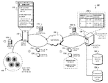
- FIG. 1 illustrates an example of a micro-location monitoring technique for a mobile device 110 . More particularly, the figure illustrates an array of beacons that are physically arranged within different geographical areas inside of a building. In this example, beacons within the location are arranged in two distinct groups (e.g., group of beacons 102 a and 102 b ), each of which include 28 individual beacons.
- group of beacons 102 a and 102 b each of which include 28 individual beacons.
- the beacons included in group 102 a includes beacons A 1 -A 28
- the beacons included in group 102 b includes beacons B 1 -B 28 .
- the mobile device 110 is configured to be capable of only monitoring twenty beacons simultaneously at any given regardless of the number of deacons that are potentially detectable because the mobile device is within their broadcast range. For instance, when the mobile device 110 enters the building through the entrance, the mobile device 110 is initially located at a position that is indicated with the letter “A” (referred hereinafter as “position A”). The mobile device 110 can then move to an updated position that is indicated with the letter “B” (referring hereinafter as “position B”).
- the mobile device 110 may be located within the broadcast ranges of all of the beacons within the building (e.g., beacons A 1 -A 28 and beacons B 1 -B 28 ), or some of the beacons within the building (e.g., a particular subset of the group of beacons 102 a , and another particular subset of the group of beacons 102 b ). Regardless of the number of beacons that have broadcast ranges that include the mobile device 110 , the maximum number of beacons that are actually monitored (and hence, actually detected) by the mobile device 110 cannot exceed twenty beacons.
- beacons A 24 and A 25 in the figure may have broadcast ranges that only include position A, while the beacons B 27 and B 28 may have broadcast ranges that only include position B.
- beacons A 24 and B 25 become undetectable, whereas beacons B 27 and B 28 can potentially become detectable (assuming that the beacons B 27 and B 28 are one of the potentially detectable beacons that are actually included within the twenty beacons that are simultaneously monitored by the mobile device 110 when it is located in position B).
- each of the beacons A 1 - 28 and the beacons B 1 -B 28 may be potentially detectable within an entire area encompassing the location (e.g., an area encompassing the entire building) such that as the mobile device 110 moves from position A to position B, the change in position does not change the number of beacons that have a broadcast range that includes a current position of the mobile device 110 .
- the beacons that are actually monitored when the mobile device 110 is located in an updated position can still include beacons that were initially detected and monitored by the mobile device 110 when the mobile device was located in position A (because the detectability of these beacons has not changed since both positions A and B are included within the broadcast regions of the beacons).
- the location monitoring techniques described in FIG. 2 below can be used to enable the mobile device 110 to exchange communications with an application server that provides instructions to adjust the selective monitoring of particular subsets of beacons in relation to a detected movement of the mobile device 110 .
- the general area (e.g., a geographical area that includes the present position of the mobile device 110 ) of the mobile device 110 , and the movement of the mobile device 110 between positions (e.g., between positions included in different geographical areas) can be computing using a variety of techniques.
- GPS data can be used to estimate a general area in which the mobile device 110 is located (e.g., inside a location that includes beacons).
- sensor data of the mobile device 110 can be used to identify the area and the movement of the mobile device 110 .
- inertial measurements by an accelerometer of the mobile device 110 and/or magnetic fields measured by a compass of the mobile device 110 in relation to the last known GPS signal of the mobile device 110 can be used to infer an estimated position within the building in relation to its position near the outside of the location.
- the system enables more precise position tracking techniques using communications with the beacons within the location (e.g., identifying connection events between individual reference beacons, combining connection event data with Wi-Fi transceiver data, using respective connection strengths of individual beacons in relation to a predetermined array of beacons, etc.).
- the mobile device 110 described in association with FIG. 1 may include, for example, one or more of mobile computing devices, personal digital assistants (PDAs), cellular telephones, smartphones, tablet computing devices, laptop computing devices, electronic wearable devices, among other types of electronic devices.
- the beacons described in association with FIG. 1 may broadcast packets of data that include respective identification information using short-range radio or light techniques such as BLE or infrared communication.
- the mobile device 110 can also communicate with one or more other computing devices, such as a remote server, over a network.
- the mobile device 110 may communicate with one or more other computing devices over one or more networks, such as a local area network, a wide area network, and/or the Internet.
- One or more of the networks in the network may be wireless, such as a cellular telephone network or a Wi-Fi network.
- the beacons, the mobile device, and the one or more computers make up a system 100 described in greater detail below with respect to FIG. 2 .
- identification of the group of beacons 104 b can be based additionally or alternatively on other types of data other than communication between the mobile device 110 and the beacons illustrated in FIG. 1 .
- the group of beacons which are designated by the reference numerals 102 a and 102 b in FIG. 1 , can be determined based on global positioning system (GPS) data associated with the mobile device 110 , wireless connectivity data of the mobile device 110 , cellular data of the mobile device 110 , or a combination of such. In such instances, such data can be used to independently identify a location of the mobile device 110 in order to verify movement detection of the mobile device 110 based on the connection events with individual beacons.
- GPS global positioning system
- changes to detected Wi-Fi signal strengths by the mobile device 110 can be used, along with a known location of one or more corresponding Wi-Fi transceivers, to determine if the mobile device 110 is moving in a certain direction.
- changes to GPS location data can also be used to indicate movements of the mobile device 110 .
- movements of the mobile device 110 can be determined based on the use of geo-fences and/or other types of virtual perimeters that are associated with collections of beacons, such as the collections of beacons 102 a and 102 b shown in FIG. 1 .
- a geo-fence may define a specific geographical area within the location and may be associated with each of the beacons that are encompassed within the specific geographical area. The geo-fence can then monitor the movement of the mobile device 110 in relation to the specific geographical area.
- the mobile device 110 in response to determining that the mobile device 110 has recently traversed a virtual boundary specified by a first geo-fence, the mobile device 110 can then determine that the mobile device 110 has entered into the geographical area defined by the virtual boundary of the first geo-fence. The mobile device 110 can then automatically determine a group of beacons to begin monitoring based on their association with the first geo-fence. Using the same techniques, the mobile device 110 can also automatically determine a group of beacons to stop monitoring based on their association with a second geo-fence that the mobile device 110 recently traversed in order to exit a corresponding geographical area defined by the second geo-fence's virtual boundary.
- FIG. 2 illustrates an example of a system 100 that is capable of performing micro-location monitoring techniques for the mobile device 110 illustrated in FIG. 1 .
- the system 100 generally includes monitored beacons 103 , the mobile device 110 , and an application server 120 connected over a wireless network 105 .
- the monitored beacons 103 includes all beacons within a location that are actually monitored by the mobile device 110 when it is located at position A.
- the monitored beacons 103 can include a combination of beacons from groups 102 a and 102 b or only beacons from group 102 a depending on the particular detection used by the mobile device 110 (if the number of potentially detectable beacons exceeds the twenty beacons which the mobile device 110 can monitor at any position).
- the mobile device 110 includes an application 112 provided for output on the display of the mobile device 110 .
- the application server 120 remotely stores various types of data such as beacon data 122 for the group of wireless beacons 103 and application content data 124 to be provided on the application 112 .
- the beacon data 122 can include reference data for the location that specifies, for example, a predetermined arrangement for all beacons within the location, groupings of beacons among all beacons (e.g., groups 102 a and 102 b ), or content mappings between individual beacons (or groups of beacons) and corresponding content within the application content data 124 that is mapped to the individual beacons (or groups of beacons).
- the communication between the monitored beacons 103 , the mobile device 110 , and the application server 120 enables the mobile device 110 to selectively and intelligently monitor a particular set of beacons within the location in relation to a detected movement of the mobile device 110 in order to more accurately and precisely monitor a group of beacons that is more relevant to updated position of the mobile device 110 (e.g., the position B) after it has moved from an initial position (position A).
- the mobile device 110 initially obtains beacon broadcast data 104 a for the monitored beacons 103 .
- the obtained beacon broadcast data 104 a is then included within the beacon proximity data 104 b , which is transmitted by the mobile device 110 to the application server 120 over the network 105 .
- the identification information for the beacons e.g., beacon identifiers associated with the monitored beacons 103
- the identification information for the beacons are then processed by the application server 120 alongside data contained within the reference beacon data 122 and application content data 124 to identify (i) a particular set of beacons to monitor based on the detected movement, and (ii) application content associated with at least some of the beacons included within the particular set of beacons.
- the identified information is then provided back to mobile device 110 as application content 104 c and a monitoring instruction 104 d over the network 105 .
- the mobile device 110 then adjusts the monitoring of beacons within the location based on the monitoring instruction, and provides content specified by the application content 104 c for output on the application 112 .
- the mobile device 110 initially obtains beacon broadcast data 104 a associated with the monitored beacons 103 .
- the beacon broadcast data 104 a can include a unique identifier that is associated with each individual beacon within the monitored beacons 103 .
- the mobile device 110 detects the beacon broadcast data 104 a for the monitored beacons 103 when located the mobile device 110 initially enters the location (e.g., when located in position A).
- the monitored beacons 103 includes twenty beacons from among the among the group of beacons 102 a and the group of beacons 102 b within the location illustrated in FIG. 1 .
- the monitored beacons 103 includes a subset of the group of the beacons 102 a and another subset of the group of beacons 102 b (e.g., fifteen beacons from group 102 a and five beacons from group 102 b ). In other instances, the monitored beacons 103 only includes beacons from the group 102 a (e.g., twenty beacons from group 102 a ). The variation in the individual beacons that are included within the monitored beacons 103 may be attributable to, for example, the technique used by the mobile device 110 to monitor a threshold number of beacons when a larger number of beacons are potentially detectable (e.g., have a broadcast range that includes a current position of the mobile device 110 ).
- the obtained beacon broadcast data 104 a for the monitored beacons 103 is included within the beacon proximity data 104 b , which is then transmitted to the application server 120 over the network 105 .
- the beacon proximity data 104 b can include, for example, unique identifiers for each of the individual beacons of the monitored beacons 103 .
- the beacon proximity data 104 b can also include a location identifier that identifies the particular position in which mobile device 110 is presently located.
- the beacon proximity data 104 b also include movement data detected by the mobile device 110 when located at the position A.
- location data can include, sensor data indicating a direction of movement (e.g., based on compass data collected by the mobile device 110 ), a rate of travel (e.g., based on accelerometer data), among other types of movement information.
- the movement data can be used to indicate a rate of change in the position of the mobile device 110 in relation to an initial position (e.g., position A) in order to estimate an updated position (e.g., position B).
- the movement data can also be ascertained based on detected connection events with certain designated beacons that have very small broadcast ranges such that the detection of a connection event between the mobile device 110 and the designated beacons can be used to that the mobile device 110 was nearby the designated beacon.
- the beacons A 18 and B 15 illustrated in FIG. 1 can represent examples of designated beacons. As the mobile device 110 moves between position A and position B, connection events between the mobile device 110 and the beacons A 18 and B 15 within the indicated waypoint of movement can be used to estimate the direction of travel relative to the position A in order to predict that the updated position of the mobile device 110 will be position B at some later point in time.
- the transmitted beacon proximity data 104 b can include other types of data detected by the mobile device 110 in relation to connection events with individual beacons within the monitored beacons 103 .
- the beacon proximity data 104 b can include signal connection strengths for each of the beacons within the monitored beacons 103 .
- the signal connection strengths can be descriptive of a predicted distance between the mobile device 110 and a corresponding beacon.
- a mobile device 110 can detect connection events with the twenty beacons that are monitored by the mobile device when located in position A.
- Each of these twenty beacons can be associated with the same geographical area within a location (e.g., a department within a store) and physically arranged such that when the mobile device 110 is in a particular position within the geographical area (e.g., position A), each of the twenty that are being monitored by the mobile device 110 are in different directions relative to position of the mobile device 110 . (e.g., North, West, and South West).
- beacons that are further away can be detected to have a lower signal strength compared to beacons that are closer to the mobile device 110 .
- the detected signal strengths can be used to indicate how far individual beacons are placed in relation to a particular position of the mobile device 110 .
- the server 120 compares the data included within the beacon proximity data 104 b (e.g., identification information for each of the monitored beacons 103 ), movement data associated with the mobile device 110 , and reference information for all beacons within the location stored within the beacon data 122 .
- the comparison can be used to identify (i) a particular set of beacons for the mobile device 110 to monitor when located at an updated position (e.g., position B), and (ii) application content related to products physically placed at the position B that are associated with the particular set of beacons.
- the server 120 identifies the particular set of beacons by cross-referencing the identification information for the monitored beacons 103 (indicating the beacons that were being monitored by the mobile device 110 when located in the position A), and reference beacon arrangement information that indicates how the detected beacons 103 are arranged in relation to all beacons within the location.
- the server 120 then utilizes content mappings indicated within a repository 310 stored within the beacon data 122 in order to identify the content associated with the particular set of beacons.
- the server 120 identifies more appropriate set of beacons for the mobile device 110 to monitor given the movement data included within the beacon proximity data 104 b . For example, because mobile device 110 moves toward the top right portion of the building, the server 120 determines that it is more optimal for the mobile device 110 to monitor beacons B 13 and B 14 , which are indicated in the predetermined array to be closer to the position B relative to beacons A 18 and A 13 . Thus, in this example, the server 120 generates a monitoring instruction 104 d that instructs the mobile device 110 to stop monitoring beacons A 18 and A 13 , and start monitoring beacons B 13 and B 14 .
- the server 120 generates application content 104 c to include this content from the application content data 124 .
- the server 120 can also, for example, identify a location identifier (e.g., descriptive alphanumeric “4FKIDSSPORT,” or non-descriptive, purely numeric “114549”) included within the beacon proximity data 104 b in order to determine a location (e.g., “fourth floor kids sporting goods department”) for which beacon data should be processed.
- a location identifier e.g., descriptive alphanumeric “4FKIDSSPORT,” or non-descriptive, purely numeric “114549”
- the server 120 can also identify the beacon identifiers included within the beacon proximity data 104 b in order to identify the group of beacons 103 .
- the beacon data 122 can include data related the group of beacons 103 .
- the beacon data 122 can include a predetermined beacon array indicating their physical arrangement within the location in which the mobile device 110 is presently located.
- multiple beacons can be placed in a grid arrangement with specified distances between each individual beacon (e.g., the arrangement of the groups of beacons 102 a and 102 b illustrated in FIG. 1 ).
- Other examples of physical arrangements include circular arrangements surrounding a point of interest within a location, or a linear arrangement along a straight path within a location.
- the beacon data 122 can specify a type of physical arrangement corresponding to the group of beacons 103 , and coordinate points associated with each individual beacon identifying a positioning of each individual beacon within the physical arrangement.
- the application content data 124 can include various types of electronic content that may be of interest to a user when he/she is physically present at the updated location of the mobile device 110 (e.g., position B).
- the application content data 124 can include electronic advertisements that are provided for sale in specific areas or positions within the location, information related to points of interest within the location, or notifications to display to the user when the mobile device 110 is determined to be in a particular position within the location.
- the location is a store that sells products for purchase and the application content data 124 includes advertisements, sales offers, notifications, and/or other types of electronic content that is related to the products that are available for purchase at the store.
- the location is a museum that provides different exhibits for display in different areas of the museum.
- the application content data 124 can include informational data that is related to each of the exhibits that are provided for display in the museum.
- the location is a convention center where a conference with different events is being held.
- the application content data 124 can include event information data, or other types of electronic content that are relevant to the event that is taking place near certain areas or regions within the location.
- the server 120 transmits the application content 104 c and the monitoring instruction 104 d to the mobile device 110 over the network 105 .
- the application content 104 c includes content that is associated with the particular set of beacons that the server 120 determines is more likely to be relevant to the updated location of the mobile device 110 (e.g., the position B) based on the detected movement data of the mobile device 110 .
- the application content 104 c may include content for all or some of the particular set of beacons based on the location.
- the monitoring instruction is provided such that the particular set of beacons replaces the beacons A 18 and A 13 with the beacons B 13 and B 14 within the monitored beacons 103 .
- the application content 104 c includes content only associated with the beacons B 13 and B 14 (e.g., a subset of the particular set of beacons) because the movement data indicates that content associated with other beacons in the particular set of beacons (e.g., beacons included in group 102 a ) such as “KID'S SHOES” are no longer relevant to the products that are placed at the physical location within the building corresponding to position B.
- the application content 104 c thus includes only content associated with beacons B 13 and B 14 (e.g., “MEN'S SHOES” and “NEW ARRIVALS”).
- the mobile device 110 then configures the monitoring of beacons in the location in accordance with the monitoring instruction 104 d , and provides the content included within the application content 104 c for output on the mobile device 110 through the application 112 .
- the mobile device 110 terminates prior monitoring of the beacons A 18 and A 13 (e.g., which was initiated when located in the position A), and initiates monitoring of beacons B 13 and B 14 .
- the mobile device 110 also configures the application 112 provides content included within the application content 104 c (e.g., information related to “MEN'S SHOES” and “NEW ARRIVALS”).
- the application 112 presents a user interface that allows the user to perceive individual beacons that are presently being monitored by the mobile device 110 after reconfiguring its monitoring in accordance with the monitoring instruction 104 d (e.g., beacons B 13 and B 14 ), and associated electronic content that is included within the received application content 104 c (e.g., information related to “MEN'S SHOES” and “NEW ARRIVALS”).
- the electronic content can include sales discounts for shoe products that are near the present position of the mobile device 110 within the location and/or informational data indicating new shoe products that have recently arrived in the store.
- the techniques described above with respect to FIGS. 1 and 2 enable the mobile device 110 to monitor new beacons (e.g., beacons B 13 and B 14 ) that were not previously included in an initial set of monitored beacons (e.g., the monitored beacons 103 ), and provide content associated with the two newly monitored beacons (e.g., information related to “MEN'S SHOES” and “NEW ARRIVALS”) in relation to a detected movement of the mobile device 110 from position A to position B.
- new beacons e.g., beacons B 13 and B 14
- content associated with the two newly monitored beacons e.g., information related to “MEN'S SHOES” and “NEW ARRIVALS”
- the communications between the mobile device 110 and the server 120 therefore enable the mobile device 110 to intelligently and selectively monitor a particular set of beacons, below its specified threshold, so that beacons that are more relevant to the updated position of the mobile device 110 after it has completed its movement are monitored as opposed beacons that are still detectable when the mobile device 110 is located in the updated position, but are no longer relevant to the updated position (e.g., beacons A 18 and A 13 ).
- FIGS. 3A and 3B illustrate examples of specific micro-location monitoring techniques.
- FIG. 3A illustrates a micro-location monitoring technique for providing different types of content when the mobile device 110 is detected in different areas of a location.
- FIG. 3B illustrates a micro-location monitoring technique for tracking the movement of the mobile device 110 throughout different areas of the location.
- geographical areas of a location may include multiple beacons placed within them.
- the mobile device 110 may only be capable of monitoring twenty of the 140 beacons at any instance in time.
- the micro-location monitoring techniques described throughout can be used to enable the mobile device 110 to receive information from the application server 120 as to which particular beacons to monitor at a predicted position of the mobile device 110 .
- each of these beacons can be associated with the same electronic content such that when the mobile device 110 is located within the overlapping region, the shared content is provided for output on the mobile device 110 .
- multiple beacons placed in the same geographical area can be configured such that they do not share overlapping broadcast regions (e.g., to prevent multiple beacon detection when the mobile device 110 is located in a specified position). For instance, the beacons may either be placed at a sufficient distance from one another, or have their broadcast powers reduced in order to decease their corresponding broadcast ranges.
- the system 100 can use micro-location monitoring techniques to detect changes in present position of the mobile device 110 within a store 300 .
- the detected changes can then be used to dynamically update the content that is displayed on the application 112 .
- the dynamic updates can be provided based on communications between mobile device 110 , individual beacons placed in different areas of the store 300 , and the application server 120 .
- the dynamic updates can be used to provide users with more relevant content and/or information related to nearby products or points of interest in different areas of the store 300 .
- a present position 310 a of the mobile device 110 is within a broadcast range of the beacon 302 a .
- the beacon 302 a broadcasts beacon information (e.g., the beacon broadcast data 104 a ) to all mobile devices that enter into the store 300 .
- a request for content that includes the detected information can then be automatically transmitted to the application server 120 .
- the application server 120 identifies relevant application content within the stored application content data 122 that is associated with the beacon 302 a using the detected beacon broadcast information included within the received content request.
- the relevant application content is then provided to the mobile device 310 a for output on the user interface 312 a.
- the present position 310 a determined for the mobile device 110 indicates that the mobile device 310 a is presently located near the entrance of the store.
- the interface 312 a displays a welcome message for the fictional store, “MEN'S SUIT FACTORY.”
- the interface 312 a also provides general sales information that applies to all products being sold within the store 300 .
- the system 100 determines that a present position 310 b of the mobile device 110 is within a broadcast range of a beacon 302 b .
- the application server 120 provides electronic content related to men's clothing products for output on an interface 312 b of the application 112 .
- beacon information for the beacon 302 b stored within the beacon data 122 is associated with men's clothing products such as dress shirts, chinos, and khakis.
- the application server 120 Based on a detected communication event between the mobile device 110 and the beacon 302 b , the application server 120 then provides electronic content associated with men's clothing for output on the application 112 .
- the system 100 determines that a present position 310 c of the mobile device 110 is within a broadcast range of a beacon 302 c .
- the application server 120 provides electronic content related to men's shoes for output on an interface 312 c of the application 112 .
- the beacon 302 c is placed in the men's shoes department, beacon information for the beacon 302 c stored within the beacon data 122 is associated with men's shoes such as the most popularly purchased shoes by other others.
- the application server 120 Based on the detected communication event between the mobile device 110 and the beacon 302 c , the application server 120 then provides electronic content associated with men's shoes for output on the application 112 .
- respective positions of the mobile device 110 within the store 300 A at different time points are inferred based on detected communication events between the corresponding beacons placed in the different areas of the store 300 .
- the detected connection events can be used to provide area-specific content that is currently relevant to the user for output on the application 112 .
- electronic content examples include coupons, emails, gift cards, and the like, and may also be determined by the application server 120 based on determining that the mobile device 110 has received one or more of the unique identifiers for beacons that are associated with the corresponding electronic content.
- the system 100 can use micro-location monitoring techniques to identify a pathway taken by the user associated with the mobile device 110 in navigating through a store 300 B.
- the identified pathway can be used to determine, by either the mobile device 110 or the server 120 , various parameters that are descriptive of user activity within the store 300 B.
- an example of a user activity parameter can include a total amount of time spent in each area of the store 300 B, which can be used to characterize a user preference for products that are available for purchase in each area of the store 300 B.
- a user activity parameter can include an order in which a user visits particular areas of the store 300 B, which can be used to identify user priorities in relation to products that are available for purchase in each area of the store 300 B.
- the pathway taken by the user associated with the mobile device 110 can determined based on tracking the present position of the mobile device 110 over the period of time in which the mobile device 110 is located within the store 300 B.
- communication between individual beacons within the location and the mobile device 110 can be used to estimate a present position of the mobile device 110 within a location based on known reference positions associated with each of the individual beacons within a predetermined array of beacons.
- a detected connection event between the mobile device 110 and the beacon 302 a can be used to identify a geographical area or area within the store 300 B in which the mobile device 110 is presently located. Additional information, such as connection signal strengths of the detected beacons, or signals obtained from multiple beacons within the same geographical areas can then be used to estimate a specific position of the mobile device 110 within the area in which the mobile device 110 is presently located.
- the techniques to estimate the position of the mobile device 110 can be performed periodically over time intervals in order to track the movement of mobile device 110 within the store 300 B over a period of time. In some instances, such techniques can be performed in real-time in order to identify real-time changes to the position of the mobile device 110 based on changes to respective connection signal strengths of detected beacons within the broadcast range of the mobile device 110 . For example, a diminishing connection signal strength can be used to indicate that the mobile device 110 is moving away from a particular beacon, whereas an increasing connection signal strength can be used to indicate that the mobile device 110 is moving toward a particular beacon.
- measured connection signal strengths from multiple beacons placed in the same area can be used to determine a direction of movement of the mobile device 110 .
- an area in which the mobile device 110 is located includes two beacons, a first beacon placed north of the mobile device 110 and a second beacon placed south of the mobile device 110 . If the monitored connection signal strength between the mobile device and the beacons is increasing for the first beacon, but decreasing for the second beacon, then the system 100 determines that the mobile device 110 is moving north from a prior position.
- position tracking techniques can be supplemented, augmented, or validated using other types of sensor data that are obtained independently from the communication between the mobile device 110 and the beacons placed within a location.
- the mobile device 110 may obtain one or more of GPS data, accelerometer data, Wi-Fi connectivity data, or other types of wireless communication data in order to independently verify the movement of the mobile device 110 throughout the store 300 B.
- GPS data can be used to identify an initial baseline position of the mobile device 110 prior a user entering an indoor location.
- Accelerometer data, inertial measurement data, and compass data can then be used to track changes in the baseline position based on determining a rate of motion and a direction of movement.
- the system 100 can then compare a predicted position determined based on the locations of beacons to a predicted position measured using the other types of sensor data to measure a correspondence between the two different measurements.
- the mobile device 110 may periodically track the initiation and termination of connection events between the mobile device 110 and individual beacons as the mobile device moves throughout different areas of the store 300 B.
- the detected connection events can then be stored in a table 310 that specifies a beacon identifier, an associated area within the store 300 B, and a time point associated with the start of the connection event.
- a table 310 specifies a beacon identifier, an associated area within the store 300 B, and a time point associated with the start of the connection event.
- the user initially moves from the store entrance to the men's clothing department between 12:03 PM and 12:04 PM, correspond to time points for the connection events between the mobile device 110 and the beacon 302 a and the mobile device 110 and the beacon 302 b , respectively.
- the user then moves toward the men's shoes department between 12:04 PM and 12:09 PM, the later of which corresponds to the connection event between the mobile device 110 and the beacon 302 c .
- the user finally makes his/her way towards the exit of the store 300 B between 12:09 PM and 12:27 PM, the later of which corresponds to the connection event between the mobile device 110 and the beacon 302 a as the user exits the store 300 B.
- a comparison of time points associated with connection events can then be used to determine total times 320 a and 320 b that the user has spent in the men's clothing department and the men's shoes departments, respectively, of the store 300 B.
- data within the table 310 indicates that the user spent a greater amount of time in the men's shoes department over the men's clothing department, indicating that the user may have a greater preference towards men's shoes products compared to men's clothing products.
- the waypoint of detected movement indicates that the user visited a larger amount of the area of the men's shoes department compared to the area visited in the men's clothing department, further indicating a greater preference towards men's shoes products compared to men's clothing products.
- beacons can be grouped in various ways (e.g., twenty beacons can be grouped within the same department or spread throughout the store).
- the micro-location monitoring techniques employed by the system 100 can be used to satisfy various business objectives.
- the arrangement of beacons within the retail environment e.g., physical placement of the beacons in certain areas
- the configuration of the beacons and/or other supporting devices e.g., geo-fences, Wi-Fi access points, etc.
- the particular micro-location techniques utilized by the system 100 can therefore be adjusted based on the particular retail environment used.
- sets of beacons may be customized for particular users so as to monitor for beacons that are associated with products that are most frequently purchased by each user.
- sets of beacons may be tailored to different marketing campaigns/initiatives.
- techniques can also be used enable the determination enhanced business analytics as illustrated in FIG. 3B .
- Other information relating to a particular store and the user can also be used by the system 100 in conjunction with data provided by these techniques to derive granular insights associated with consumer habits and trends. Such data can be further used as feedback in order to dynamically adjust beacon groupings and achieve different business objectives.
- FIG. 4 illustrates an example of a process 400 for monitoring changes to micro-locations associated with a mobile device.
- the process 400 can include determining that a mobile device has moved from a first geographical area to a second geographical area ( 410 ), sending a request to a server for a list of beacons associated with the second geographical area ( 420 ), receiving a list of a particular set of beacons from the server ( 430 ), and scanning for information that is being broadcast by the particular set of beacons ( 440 ).
- the process 400 can include determining that a mobile device has moved from a first geographical area to a second geographical area ( 410 ). For instance, as described above with respect to FIG. 1 , the mobile device 110 may determine that it has moved from a geographical area associated with the collection of beacons 102 a to a geographical area associated with the collection of beacons 102 b . This determination can be based on a variety of factors as described above. In some implementations, the determination is based on identifying connection events with individual beacons that are between the two geographical areas such as beacons 1 and 2 illustrated in FIG. 1 .
- the determination that the mobile device 110 has moved can be augmented and/or adjusted using other types of sensor data that indicate a location and/or movement of the mobile device 110 (e.g., GPS data, Wi-Fi connectivity data, cellular network data, accelerometer data, magnetic fields, etc.).
- GPS data can be used to determine a present position of the mobile device within a geographical area of the location
- accelerometer data can be used to determine a predicted direction of movement of the mobile device within the geographical area.
- the initial position indicated by the GPS data, along with the direction of movement and the connection event data can be used to precisely identify a movement of the mobile device 110 between geographical areas.
- the mobile device 110 may also precisely identify a change in position of the mobile device 110 (e.g., a change from an initial position within the geographical area associated with the group of beacons 102 a to an updated position within the geographical area associated with the group of beacons 102 b ). In such implementations, the mobile device 110 may determine a predicted position within the new geographical area based on respective signal connection strengths for beacons within the geographical area. For example, as described above, a stronger signal strength can be used to indicate that the mobile device 110 is closer to a particular beacon, whereas a weaker signal strength can be used to indicate that the mobile device 110 is farther from another beacon.
- the process 400 can include sending a request to a server for a set of beacons associated with the second geographical area ( 420 ).
- the mobile device 110 may send a request for a list of beacons associated with the second geographical area (e.g., the geographical associated with the collection of beacons 102 b ) to the application server 120 .
- the request can include beacon proximity data 102 b for the collection of beacons 102 b based on connection events with the mobile device 110 .
- the request may include other types of information that enables the application server 120 to predict an updated position of the mobile device 110 , and the beacons within the collection of beacons 102 b that are closest to the mobile device 110 .
- the process 400 can include receiving a list of a particular set of beacons from the server ( 430 ).
- the mobile device 110 may receive a list of a particular set of beacons from the application server 120 .
- the particular set of beacons can represent one or more beacons from among the group of beacons 102 b that are determined to be within a proximity to the mobile device 110 (e.g., beacons that are closes to the mobile device 110 within a new geographical area that the mobile device 110 has moved to).
- the mobile device 110 may obtain data associated with the particular set of beacons from the application server 120 .
- the mobile device 110 may receive application content 104 c associated with the particular set of beacons.
- the application content 104 c can specify, for example, electronic content from the stored application content 124 that is mapped to the particular set of beacons within the stored beacon data 122 .
- the application content 104 c can also include beacon information stored within the beacon data 122 .
- the beacon information can include a physical arrangement of the particular set of beacons that were included in the request sent to the application server 120 .
- the process 400 can include scanning for information that is being broadcast by the particular set of beacons ( 440 ).
- the mobile device 110 may scan for information that is being broadcast by the particular set of beacons in response to receiving data from the application server 120 .
- the mobile device 110 may obtain electronic content associated with beacons that are determined to be nearby a predicted position of the mobile device 110 within a new geographical area that the mobile device 110 has moved to.
- the obtained electronic content can be content that is relevant to products that are available for purchase nearby the predicted location of the mobile device 110 .
- the mobile device 110 may selectively enable monitoring of some beacons while selectively disabling monitoring of other beacons in order to ensure that the total number of beacons monitored by the mobile device 110 is below a specified threshold for the mobile device 110 .
- the mobile device in response to determining that the mobile device has moved from a geographical area associated with the collection of beacons 102 a to a geographical area associated with the collection of beacons 102 b , the mobile device may disable existing wireless monitoring of one or more beacons within the collection of beacons 102 a and also enable existing monitoring of one or more beacons within the particular set of beacons identified by the server and also included within the collection of beacons 102 b .
- monitoring of beacons within the group of beacons 102 a is disabled since the movement of the mobile device 110 has changed its position such that the content associated with the beacons in this group are no longer relevant to the updated position of the mobile device 110 .
- FIG. 5 is a schematic diagram of an example of a computer system 500 .
- the system 500 can be used for the operations described in association with FIG. 1 according to some implementations.
- the system 500 may be included in the system 100 .
- the system 500 includes a processor 510 , a memory 550 , a storage device 530 , and an input/output device 540 .
- Each of the components 510 , 550 , 530 , and 540 are interconnected using a system bus 550 .
- the processor 510 is capable of processing instructions for execution within the system 500 .
- the processor 510 is a single-threaded processor.
- the processor 510 is a multi-threaded processor.
- the processor 510 is capable of processing instructions stored in the memory 550 or on the storage device 530 to display graphical information for a user interface on the input/output device 540 .
- the memory 550 stores information within the system 500 .
- the memory 550 is a computer-readable medium.
- the memory 550 is a volatile memory unit.
- the memory 550 is a non-volatile memory unit.
- the storage device 530 is capable of providing mass storage for the system 500 .
- the storage device 530 is a computer-readable medium.
- the storage device 530 may be a floppy disk device, a hard disk device, an optical disk device, or a tape device.
- the input/output device 540 provides input/output operations for the system 500 .
- the input/output device 540 includes a keyboard and/or pointing device.
- the input/output device 540 includes a display unit for displaying graphical user interfaces.
- the features described can be implemented in digital electronic circuitry, or in computer hardware, firmware, software, or in combinations of them.
- the apparatus can be implemented in a computer program product tangibly embodied in an information carrier, e.g., in a machine-readable storage device, for execution by a programmable processor; and method steps can be performed by a programmable processor executing a program of instructions to perform functions of the described implementations by operating on input data and generating output.
- the described features can be implemented advantageously in one or more computer programs that are executable on a programmable system including at least one programmable processor coupled to receive data and instructions from, and to transmit data and instructions to, a data storage system, at least one input device, and at least one output device.
- a computer program is a set of instructions that can be used, directly or indirectly, in a computer to perform a certain activity or bring about a certain result.
- a computer program can be written in any form of programming language, including compiled or interpreted languages, and it can be deployed in any form, including as a stand-alone program or as a module, component, subroutine, or other unit suitable for use in a computing environment.
- Suitable processors for the execution of a program of instructions include, by way of example, both general and special purpose microprocessors, and the sole processor or one of multiple processors of any kind of computer.
- a processor will receive instructions and data from a read-only memory or a random access memory or both.
- the elements of a computer are a processor for executing instructions and one or more memories for storing instructions and data.
- a computer will also include, or be operatively coupled to communicate with, one or more mass storage devices for storing data files; such devices include magnetic disks, such as internal hard disks and removable disks; magneto-optical disks; and optical disks.
- Storage devices suitable for tangibly embodying computer program instructions and data include all forms of non-volatile memory, including by way of example semiconductor memory devices, such as EPROM, EEPROM, and flash memory devices; magnetic disks such as internal hard disks and removable disks; magneto-optical disks; and CD-ROM and DVD-ROM disks.
- semiconductor memory devices such as EPROM, EEPROM, and flash memory devices
- magnetic disks such as internal hard disks and removable disks
- magneto-optical disks and CD-ROM and DVD-ROM disks.
- the processor and the memory can be supplemented by, or incorporated in, ASICs (application-specific integrated circuits).
- ASICs application-specific integrated circuits
- the features can be implemented on a computer having a display device such as a CRT (cathode ray tube) or LCD (liquid crystal display) monitor for displaying information to the user and a keyboard and a pointing device such as a mouse or a trackball by which the user can provide input to the computer.
- a display device such as a CRT (cathode ray tube) or LCD (liquid crystal display) monitor for displaying information to the user and a keyboard and a pointing device such as a mouse or a trackball by which the user can provide input to the computer.
- the features can be implemented in a computer system that includes a back-end component, such as a data server, or that includes a middleware component, such as an application server or an Internet server, or that includes a front-end component, such as a client computer having a graphical user interface or an Internet browser, or any combination of them.
- the components of the system can be connected by any form or medium of digital data communication such as a communication network. Examples of communication networks include, e.g., a LAN, a WAN, and the computers and networks forming the Internet.
- the computer system can include clients and servers.
- a client and server are generally remote from each other and typically interact through a network, such as the described one.
- the relationship of client and server arises by virtue of computer programs running on the respective computers and having a client-server relationship to each other.
Abstract
Description
Claims (22)
Priority Applications (5)
| Application Number | Priority Date | Filing Date | Title |
|---|---|---|---|
| US15/299,369 US9894475B2 (en) | 2015-10-20 | 2016-10-20 | Micro-location monitoring techniques |
| US15/850,478 US10362437B1 (en) | 2015-10-20 | 2017-12-21 | Micro-location monitoring techniques |
| US16/518,042 US20190342697A1 (en) | 2015-10-20 | 2019-07-22 | Micro-location monitoring techniques |
| US16/986,752 US11323840B2 (en) | 2015-10-20 | 2020-08-06 | Micro-location monitoring techniques |
| US17/734,538 US11864052B2 (en) | 2015-10-20 | 2022-05-02 | Micro-location monitoring techniques |
Applications Claiming Priority (2)
| Application Number | Priority Date | Filing Date | Title |
|---|---|---|---|
| US201562243993P | 2015-10-20 | 2015-10-20 | |
| US15/299,369 US9894475B2 (en) | 2015-10-20 | 2016-10-20 | Micro-location monitoring techniques |
Related Child Applications (1)
| Application Number | Title | Priority Date | Filing Date |
|---|---|---|---|
| US15/850,478 Continuation US10362437B1 (en) | 2015-10-20 | 2017-12-21 | Micro-location monitoring techniques |
Publications (2)
| Publication Number | Publication Date |
|---|---|
| US20170111763A1 US20170111763A1 (en) | 2017-04-20 |
| US9894475B2 true US9894475B2 (en) | 2018-02-13 |
Family
ID=58523163
Family Applications (6)
| Application Number | Title | Priority Date | Filing Date |
|---|---|---|---|
| US15/299,369 Active US9894475B2 (en) | 2015-10-20 | 2016-10-20 | Micro-location monitoring techniques |
| US15/850,478 Active US10362437B1 (en) | 2015-10-20 | 2017-12-21 | Micro-location monitoring techniques |
| US16/518,042 Abandoned US20190342697A1 (en) | 2015-10-20 | 2019-07-22 | Micro-location monitoring techniques |
| US16/986,752 Active US11323840B2 (en) | 2015-10-20 | 2020-08-06 | Micro-location monitoring techniques |
| US17/734,538 Active US11864052B2 (en) | 2015-10-20 | 2022-05-02 | Micro-location monitoring techniques |
| US18/142,209 Pending US20230263386A1 (en) | 2015-10-20 | 2023-05-02 | Method and device for detection and assessment of marijuana impairment |
Family Applications After (5)
| Application Number | Title | Priority Date | Filing Date |
|---|---|---|---|
| US15/850,478 Active US10362437B1 (en) | 2015-10-20 | 2017-12-21 | Micro-location monitoring techniques |
| US16/518,042 Abandoned US20190342697A1 (en) | 2015-10-20 | 2019-07-22 | Micro-location monitoring techniques |
| US16/986,752 Active US11323840B2 (en) | 2015-10-20 | 2020-08-06 | Micro-location monitoring techniques |
| US17/734,538 Active US11864052B2 (en) | 2015-10-20 | 2022-05-02 | Micro-location monitoring techniques |
| US18/142,209 Pending US20230263386A1 (en) | 2015-10-20 | 2023-05-02 | Method and device for detection and assessment of marijuana impairment |
Country Status (1)
| Country | Link |
|---|---|
| US (6) | US9894475B2 (en) |
Cited By (3)
| Publication number | Priority date | Publication date | Assignee | Title |
|---|---|---|---|---|
| US20160323803A1 (en) * | 2015-04-30 | 2016-11-03 | Mist Systems, Inc. | Methods and apparatus relating to the use of real and/or virtual beacons |
| US10932141B2 (en) | 2015-04-30 | 2021-02-23 | Juniper Networks, Inc. | Methods and apparatus for generating,transmitting and/or using beacons |
| US11864052B2 (en) | 2015-10-20 | 2024-01-02 | Perfect Sense, Inc. | Micro-location monitoring techniques |
Families Citing this family (23)
| Publication number | Priority date | Publication date | Assignee | Title |
|---|---|---|---|---|
| US8781502B1 (en) * | 2013-02-01 | 2014-07-15 | Swirl Networks, Inc. | Systems and methods for display of supplemental content responsive to location |
| DE102013205547B4 (en) * | 2013-03-28 | 2018-01-11 | Siemens Aktiengesellschaft | Method for determining the location of a mobile device within a building and devices for carrying it out |
| US10321265B2 (en) * | 2015-11-18 | 2019-06-11 | International Business Machines Corporation | Diagnosis of beacons in an open architecture |
| WO2017180503A1 (en) * | 2016-04-11 | 2017-10-19 | The Regents Of The University Of Michigan | Magnetic beacon and inertial sensor localization technology |
| CN107306425B (en) * | 2016-04-20 | 2021-01-29 | 华为技术有限公司 | Equipment configuration method and device |
| US20170339525A1 (en) * | 2016-05-17 | 2017-11-23 | Andrew Schrader | UUID Entity Update |
| US10231078B1 (en) * | 2016-05-31 | 2019-03-12 | Infinite Leap, Inc. | Bluetooth low energy (BLE) real-time location system (RTLS) having simple transmitting tags, beacons and bridges, that use a combination of motion detection and RSSI measurements to determine room-location of the tags |
| US10251020B1 (en) * | 2016-05-31 | 2019-04-02 | Infinite Leap, Inc. | Bluetooth low energy (BLE) real-time location system (RTLS) having tags, beacons and bridges, that use a combination of motion detection and RSSI measurements to determine room-location of the tags |
| US10254378B1 (en) * | 2016-07-05 | 2019-04-09 | Phunware, Inc. | Mobile device localization based on relative received signal strength indicators |
| US10459103B1 (en) * | 2016-09-29 | 2019-10-29 | Amazon Technologies, Inc. | Magnetic entry portal identification system |
| US10861049B2 (en) * | 2016-11-04 | 2020-12-08 | Dynasign Corporation | Global-scale wireless ID marketing registry system for mobile device proximity marketing |
| JP6776848B2 (en) * | 2016-11-25 | 2020-10-28 | 富士通株式会社 | Information processing system, information processing device and information processing method |
| US10714216B1 (en) * | 2017-08-30 | 2020-07-14 | Swipesense, Inc. | Method and system for increasing accuracy of hygiene compliance determinations |
| US11057819B2 (en) * | 2017-09-22 | 2021-07-06 | Intel Corporation | Physical web beacon, client and proxy |
| CN108769972B (en) * | 2018-07-12 | 2020-10-13 | 南昌黑鲨科技有限公司 | Connection control method and Bluetooth connection control system for intelligent terminal and Bluetooth equipment |
| US11297568B2 (en) | 2019-01-18 | 2022-04-05 | T-Mobile Usa, Inc. | Location-based apparatus management |
| US11146934B2 (en) * | 2019-03-29 | 2021-10-12 | Aptiv Technologies Limited | System and method of reducing a communication range |
| US11252031B2 (en) | 2019-11-20 | 2022-02-15 | T-Mobile Usa, Inc. | Coordinated management of IoT device power consumption and network congestion |
| US11074799B1 (en) * | 2020-01-24 | 2021-07-27 | T-Mobile Usa, Inc. | Modular tracking device |
| US11493586B2 (en) * | 2020-06-28 | 2022-11-08 | T-Mobile Usa, Inc. | Mobile proximity detector for mobile electronic devices |
| US11588230B2 (en) | 2020-11-12 | 2023-02-21 | Aptiv Technologies Limited | System for transmitting radio frequency signals from a vehicle |
| WO2022125596A1 (en) * | 2020-12-07 | 2022-06-16 | Wgrs Licensing Company, Llc | Systems and methods for displaying and using discrete micro- location identifiers |
| US20230126424A1 (en) * | 2021-10-26 | 2023-04-27 | Hewlett-Packard Development Company, L.P. | Device location determinations |
Citations (6)
| Publication number | Priority date | Publication date | Assignee | Title |
|---|---|---|---|---|
| US20060287813A1 (en) * | 2003-10-31 | 2006-12-21 | Aaron Quigley | Proximate location detection system and method |
| US8199051B2 (en) | 2009-12-18 | 2012-06-12 | Trueposition, Inc. | Satellite positioning receiver and proxy location system |
| US8369242B2 (en) | 2009-03-31 | 2013-02-05 | Empire Technology Development Llc | Efficient location discovery |
| US20130093627A1 (en) * | 2011-10-13 | 2013-04-18 | Microsoft Corporation | Power-aware tiered geofencing and beacon watchlists |
| US8665154B2 (en) | 2011-05-13 | 2014-03-04 | Microsoft Corporation | Modeling and location inference based on ordered beacon sets |
| US8934867B2 (en) | 2012-07-10 | 2015-01-13 | Symbol Technologies, Inc. | On-demand access tunnel between service provider network and wireless communication network |
Family Cites Families (10)
| Publication number | Priority date | Publication date | Assignee | Title |
|---|---|---|---|---|
| US6529164B1 (en) | 2000-03-31 | 2003-03-04 | Ge Medical Systems Information Technologies, Inc. | Object location monitoring within buildings |
| US20080309616A1 (en) * | 2007-06-13 | 2008-12-18 | Massengill R Kemp | Alertness testing method and apparatus |
| US8401560B2 (en) * | 2009-03-31 | 2013-03-19 | Empire Technology Development Llc | Infrastructure for location discovery |
| SI2427095T1 (en) * | 2009-05-09 | 2023-11-30 | Genentech, Inc., | Shape discrimination vision assessment and tracking system |
| US20140233443A1 (en) * | 2013-02-20 | 2014-08-21 | Qualcomm Incorporated | Link verification in a wireless network |
| WO2015096916A1 (en) * | 2013-12-23 | 2015-07-02 | Sony Corporation | Communications system, infrastructure equipment, communication terminal and method |
| US10111030B2 (en) | 2014-09-29 | 2018-10-23 | Apple Inc. | Beacon applications for content discovery and interaction |
| US9626443B2 (en) * | 2014-10-23 | 2017-04-18 | Quixey, Inc. | Searching and accessing application functionality |
| US9485721B1 (en) | 2015-02-11 | 2016-11-01 | Sprint Communications Company L.P. | Discovery of services by mobile communication devices using a service registry indexed by wireless beacons |
| US9894475B2 (en) | 2015-10-20 | 2018-02-13 | Perfect Sense, Inc. | Micro-location monitoring techniques |
-
2016
- 2016-10-20 US US15/299,369 patent/US9894475B2/en active Active
-
2017
- 2017-12-21 US US15/850,478 patent/US10362437B1/en active Active
-
2019
- 2019-07-22 US US16/518,042 patent/US20190342697A1/en not_active Abandoned
-
2020
- 2020-08-06 US US16/986,752 patent/US11323840B2/en active Active
-
2022
- 2022-05-02 US US17/734,538 patent/US11864052B2/en active Active
-
2023
- 2023-05-02 US US18/142,209 patent/US20230263386A1/en active Pending
Patent Citations (7)
| Publication number | Priority date | Publication date | Assignee | Title |
|---|---|---|---|---|
| US20060287813A1 (en) * | 2003-10-31 | 2006-12-21 | Aaron Quigley | Proximate location detection system and method |
| US8369242B2 (en) | 2009-03-31 | 2013-02-05 | Empire Technology Development Llc | Efficient location discovery |
| US8199051B2 (en) | 2009-12-18 | 2012-06-12 | Trueposition, Inc. | Satellite positioning receiver and proxy location system |
| US8665154B2 (en) | 2011-05-13 | 2014-03-04 | Microsoft Corporation | Modeling and location inference based on ordered beacon sets |
| US20130093627A1 (en) * | 2011-10-13 | 2013-04-18 | Microsoft Corporation | Power-aware tiered geofencing and beacon watchlists |
| US8810454B2 (en) | 2011-10-13 | 2014-08-19 | Microsoft Corporation | Power-aware tiered geofencing and beacon watchlists |
| US8934867B2 (en) | 2012-07-10 | 2015-01-13 | Symbol Technologies, Inc. | On-demand access tunnel between service provider network and wireless communication network |
Non-Patent Citations (3)
| Title |
|---|
| Gast, "Building Application with iBeacon," First ed., O'Reilly Media, Inc., 2015, 80 pages. |
| Martin et al., "Demo Abstract: An iBeacon Primer for Indoor Localization," BuildSys'14, 2014, 190-191 (abstract only). |
| Rehrl et al., "Combined indoor/outdoor Smartphone navigation for public transport travelers," 8 pages (abstract only). |
Cited By (8)
| Publication number | Priority date | Publication date | Assignee | Title |
|---|---|---|---|---|
| US20160323803A1 (en) * | 2015-04-30 | 2016-11-03 | Mist Systems, Inc. | Methods and apparatus relating to the use of real and/or virtual beacons |
| US10028199B2 (en) * | 2015-04-30 | 2018-07-17 | Mist Systems, Inc. | Methods and apparatus relating to the use of real and/or virtual beacons |
| US10536894B2 (en) | 2015-04-30 | 2020-01-14 | Mist Systems, Inc. | Methods and apparatus relating to the use of real and/or virtual beacons |
| US10932141B2 (en) | 2015-04-30 | 2021-02-23 | Juniper Networks, Inc. | Methods and apparatus for generating,transmitting and/or using beacons |
| US11076341B2 (en) | 2015-04-30 | 2021-07-27 | Juniper Networks, Inc. | Methods and apparatus relating to the use of real and/or virtual beacons |
| US11368856B2 (en) | 2015-04-30 | 2022-06-21 | Juniper Networks, Inc. | Methods and apparatus for generating,transmitting and/or using beacons |
| US11564147B2 (en) | 2015-04-30 | 2023-01-24 | Juniper Networks, Inc. | Methods and apparatus relating to the use of real and/or virtual beacons |
| US11864052B2 (en) | 2015-10-20 | 2024-01-02 | Perfect Sense, Inc. | Micro-location monitoring techniques |
Also Published As
| Publication number | Publication date |
|---|---|
| US11864052B2 (en) | 2024-01-02 |
| US10362437B1 (en) | 2019-07-23 |
| US20190342697A1 (en) | 2019-11-07 |
| US20230263386A1 (en) | 2023-08-24 |
| US20220264245A1 (en) | 2022-08-18 |
| US20200367011A1 (en) | 2020-11-19 |
| US20170111763A1 (en) | 2017-04-20 |
| US11323840B2 (en) | 2022-05-03 |
Similar Documents
| Publication | Publication Date | Title |
|---|---|---|
| US11323840B2 (en) | Micro-location monitoring techniques | |
| EP3432653B1 (en) | Method, system, and apparatus for determining and provisioning location information of wireless devices | |
| US8792906B2 (en) | Providing derived location information for customer relationship in response to receipt of short range wireless beacon | |
| US9880604B2 (en) | Energy efficient location detection | |
| US9813854B2 (en) | System and method for detection of indoor tracking units | |
| US8812024B2 (en) | Geo-fence entry and exit notification system | |
| KR101680151B1 (en) | Apparatus for providing indoor location information using beacons and method thereof | |
| US9084013B1 (en) | Data logging for media consumption studies | |
| US10602305B2 (en) | Signal strength determination and mobile device identification monitoring system | |
| US20140337123A1 (en) | System and method for adaptive use of geofence parameters | |
| US10834528B2 (en) | Mobile device positioning system and method | |
| US11587146B1 (en) | Wireless beacon shopping experience | |
| US20130317916A1 (en) | Location based technology for smart shopping services | |
| US20150309180A1 (en) | Indoor global positioning system | |
| US20150011237A1 (en) | Geo-fence entry and exit notification system | |
| WO2015105847A1 (en) | Systems and methods for mobile device microlocation | |
| Kwiecień et al. | Reliability of bluetooth smart technology for indoor localization system | |
| US20180195867A1 (en) | Systems and methods for indoor and outdoor mobile device navigation | |
| US10182312B1 (en) | Method and system for providing information based on location of user-device | |
| KR20180090097A (en) | Method for improving accuracy of location positioning in exhibition | |
| Abe et al. | Network-based pedestrian tracking system with densely placed wireless access points | |
| Dhanushka | Location-Based Indoor Mobile Advertising | |
| Karppinen | Indoor Positioning: Technologies and Use Cases in Retail Context | |
| Frank et al. | Indoor navigation with Bluetooth Low Energy in crowded places | |
| CN115375341A (en) | Advertisement matching system and method thereof |
Legal Events
| Date | Code | Title | Description |
|---|---|---|---|
| AS | Assignment |
Owner name: PERFECT SENSE DIGITAL LLC, VIRGINIA Free format text: ASSIGNMENT OF ASSIGNORS INTEREST;ASSIGNORS:MORGAN, BRYAN;DUPRIS, PETER;GANG, DAVID;SIGNING DATES FROM 20161122 TO 20161130;REEL/FRAME:041794/0704 Owner name: PERFECT SENSE, INC., VIRGINIA Free format text: MERGER;ASSIGNOR:PERFECT SENSE DIGITAL, LLC;REEL/FRAME:041794/0851 Effective date: 20161103 |
|
| STCF | Information on status: patent grant |
Free format text: PATENTED CASE |
|
| AS | Assignment |
Owner name: WESTERN ALLIANCE BANK, CALIFORNIA Free format text: SECURITY INTEREST;ASSIGNOR:PERFECT SENSE, INC.;REEL/FRAME:049571/0862 Effective date: 20190624 |
|
| MAFP | Maintenance fee payment |
Free format text: PAYMENT OF MAINTENANCE FEE, 4TH YR, SMALL ENTITY (ORIGINAL EVENT CODE: M2551); ENTITY STATUS OF PATENT OWNER: SMALL ENTITY Year of fee payment: 4 |
|
| AS | Assignment |
Owner name: AB PRIVATE CREDIT INVESTORS LLC, TEXAS Free format text: SECURITY INTEREST;ASSIGNOR:PERFECT SENSE, INC.;REEL/FRAME:058150/0282 Effective date: 20211116 Owner name: PERFECT SENSE, INC., VIRGINIA Free format text: RELEASE BY SECURED PARTY;ASSIGNOR:WESTERN ALLIANCE BANK;REEL/FRAME:058149/0913 Effective date: 20211116 |
|
| AS | Assignment |
Owner name: PERFECT SENSE, INC., VIRGINIA Free format text: RELEASE BY SECURED PARTY;ASSIGNOR:WESTERN ALLIANCE BANK;REEL/FRAME:058193/0010 Effective date: 20211116 |