US9878505B2 - Tool and a method for forming and assembling beams of composite material - Google Patents
Tool and a method for forming and assembling beams of composite material Download PDFInfo
- Publication number
- US9878505B2 US9878505B2 US14/567,584 US201414567584A US9878505B2 US 9878505 B2 US9878505 B2 US 9878505B2 US 201414567584 A US201414567584 A US 201414567584A US 9878505 B2 US9878505 B2 US 9878505B2
- Authority
- US
- United States
- Prior art keywords
- mandrel
- mandrels
- section
- vacuum
- inlet
- Prior art date
- Legal status (The legal status is an assumption and is not a legal conclusion. Google has not performed a legal analysis and makes no representation as to the accuracy of the status listed.)
- Active, expires
Links
Images


Classifications
-
- B—PERFORMING OPERATIONS; TRANSPORTING
- B29—WORKING OF PLASTICS; WORKING OF SUBSTANCES IN A PLASTIC STATE IN GENERAL
- B29C—SHAPING OR JOINING OF PLASTICS; SHAPING OF MATERIAL IN A PLASTIC STATE, NOT OTHERWISE PROVIDED FOR; AFTER-TREATMENT OF THE SHAPED PRODUCTS, e.g. REPAIRING
- B29C70/00—Shaping composites, i.e. plastics material comprising reinforcements, fillers or preformed parts, e.g. inserts
- B29C70/04—Shaping composites, i.e. plastics material comprising reinforcements, fillers or preformed parts, e.g. inserts comprising reinforcements only, e.g. self-reinforcing plastics
- B29C70/28—Shaping operations therefor
- B29C70/54—Component parts, details or accessories; Auxiliary operations, e.g. feeding or storage of prepregs or SMC after impregnation or during ageing
- B29C70/543—Fixing the position or configuration of fibrous reinforcements before or during moulding
-
- B—PERFORMING OPERATIONS; TRANSPORTING
- B25—HAND TOOLS; PORTABLE POWER-DRIVEN TOOLS; MANIPULATORS
- B25B—TOOLS OR BENCH DEVICES NOT OTHERWISE PROVIDED FOR, FOR FASTENING, CONNECTING, DISENGAGING OR HOLDING
- B25B11/00—Work holders not covered by any preceding group in the subclass, e.g. magnetic work holders, vacuum work holders
- B25B11/005—Vacuum work holders
-
- B—PERFORMING OPERATIONS; TRANSPORTING
- B29—WORKING OF PLASTICS; WORKING OF SUBSTANCES IN A PLASTIC STATE IN GENERAL
- B29C—SHAPING OR JOINING OF PLASTICS; SHAPING OF MATERIAL IN A PLASTIC STATE, NOT OTHERWISE PROVIDED FOR; AFTER-TREATMENT OF THE SHAPED PRODUCTS, e.g. REPAIRING
- B29C33/00—Moulds or cores; Details thereof or accessories therefor
- B29C33/76—Cores
-
- B—PERFORMING OPERATIONS; TRANSPORTING
- B29—WORKING OF PLASTICS; WORKING OF SUBSTANCES IN A PLASTIC STATE IN GENERAL
- B29C—SHAPING OR JOINING OF PLASTICS; SHAPING OF MATERIAL IN A PLASTIC STATE, NOT OTHERWISE PROVIDED FOR; AFTER-TREATMENT OF THE SHAPED PRODUCTS, e.g. REPAIRING
- B29C70/00—Shaping composites, i.e. plastics material comprising reinforcements, fillers or preformed parts, e.g. inserts
- B29C70/04—Shaping composites, i.e. plastics material comprising reinforcements, fillers or preformed parts, e.g. inserts comprising reinforcements only, e.g. self-reinforcing plastics
- B29C70/28—Shaping operations therefor
- B29C70/30—Shaping by lay-up, i.e. applying fibres, tape or broadsheet on a mould, former or core; Shaping by spray-up, i.e. spraying of fibres on a mould, former or core
- B29C70/32—Shaping by lay-up, i.e. applying fibres, tape or broadsheet on a mould, former or core; Shaping by spray-up, i.e. spraying of fibres on a mould, former or core on a rotating mould, former or core
-
- B—PERFORMING OPERATIONS; TRANSPORTING
- B29—WORKING OF PLASTICS; WORKING OF SUBSTANCES IN A PLASTIC STATE IN GENERAL
- B29D—PRODUCING PARTICULAR ARTICLES FROM PLASTICS OR FROM SUBSTANCES IN A PLASTIC STATE
- B29D99/00—Subject matter not provided for in other groups of this subclass
- B29D99/0003—Producing profiled members, e.g. beams
-
- B—PERFORMING OPERATIONS; TRANSPORTING
- B29—WORKING OF PLASTICS; WORKING OF SUBSTANCES IN A PLASTIC STATE IN GENERAL
- B29L—INDEXING SCHEME ASSOCIATED WITH SUBCLASS B29C, RELATING TO PARTICULAR ARTICLES
- B29L2031/00—Other particular articles
- B29L2031/001—Profiled members, e.g. beams, sections
- B29L2031/003—Profiled members, e.g. beams, sections having a profiled transverse cross-section
-
- B—PERFORMING OPERATIONS; TRANSPORTING
- B29—WORKING OF PLASTICS; WORKING OF SUBSTANCES IN A PLASTIC STATE IN GENERAL
- B29L—INDEXING SCHEME ASSOCIATED WITH SUBCLASS B29C, RELATING TO PARTICULAR ARTICLES
- B29L2031/00—Other particular articles
- B29L2031/772—Articles characterised by their shape and not otherwise provided for
Definitions
- the present invention relates to a method and to a tool for the forming and the assembly of “H-beams” made of fibre-reinforced polymerizable thermosetting composite material.
- an H-beam 5 is formed by the coupling of two C-section beams 10 , 16 made of carbon fibre.
- the two C-section beams 10 , 16 are joined by superposing the two webs 14 , 20 .
- filling elements 22 with a triangular cross-section are applied.
- the H-beam 5 thus assembled is then subjected to a compaction and hot forming step, and is lastly cured in an autoclave.
- the manufacturing process for the H-beam starts from a plane sheet made of carbon fibre, picked up and placed onto a forming tool comprising an elongated mandrel of appropriate shape that reproduces the shape that the plane sheet has to copy.
- the plane sheet, disposed on the mandrel is subjected to the application of vacuum and heat, inside a suitable thermo-forming station equipped with an elastic membrane. Under the application of the vacuum, the membrane adheres to the plane sheet, forcing it to bend and to reproduce the outer contour of the mandrel, according to procedures known per se (see, for example, patent publication WO 2008/155720 A2).
- the same processing steps are applied to a second plane sheet.
- Two beams 10 , 16 are thus obtained that each have a C-shaped cross-section.
- Such a cross-section defines a central web 14 , 20 from the sides of which two outer flanges 12 , 13 , 18 , 19 extend that are mutually parallel and perpendicular to the web 14 , 20 .
- the web 14 , 20 has an outer (or back) surface 14 a , 20 a and an inner surface 14 b , 20 b .
- the flanges 12 , 13 , 18 , 19 have inner surfaces 12 a , 13 a , 18 a , 19 a .
- the procedure provides for at least one of the two C-section beams 10 , 16 to be lifted, turned over by 180° and placed onto the other C-section beam, in such a manner as to make the outer backs 14 a , 20 a of the two webs 14 , 20 coincide.
- An H-beam 5 is thus obtained.
- the H-beam thus assembled is transferred into a compacting station, in which it is subjected to a hot forming step, according to procedures known per se. Successively, the H-beam is transferred onto a curing tool, together with other elements, and finally into an autoclave, where it undergoes a polymerization treatment by means of the combined action of pressure and heat.
- a general object of the present invention is to optimize and speed up the handling operations with which a carbon fibre H-beam is assembled, and at the same time improve the quality of the finished product. Then, in particular, it is desired to improve the standard of finishing of the surfaces of the finished H-beam.
- One typical objective is to avoid the finished H-beam exhibiting marks/holes caused by holding means conventionally used in the assembly step for processing the C-section beams on the respective forming mandrels.
- a further specific object is to speed up the operations for removal of the assembled H-beam from the forming and assembly tools. Yet another object is that of reducing the manual operations, generally slow and costly, to a minimum.
- a tool for forming a beam having a C cross-section made of fibre-reinforced polymerizable thermosetting composite material, typically carbon fibre.
- the forming tool comprises a mandrel having a shape elongated in a given direction and substantially rectangular or trapezoidal cross-section.
- the mandrel has three consecutive outer faces, which comprise a planar face configured to form a surface of the web of the C-section beam, and two opposing lateral faces configured to form two respective surfaces of the flanges of the C-section beam.
- the mandrel has a distributed perforation on at least one of the aforementioned three outer faces and at least one inlet/outlet connection for connecting the mandrel to at least one external source of vacuum and/or compressed air.
- One or more passages are formed inside of the mandrel, which establish a fluid communication between the distributed perforation and the inlet/outlet connection.
- the distributed perforation can perform the dual function of
- the uniform action of the pneumatic force for forming and for expulsion allows beams of a high quality to be obtained, and also the steps for preparation and for assembly of the component parts of the H-beam by polymerization to be speeded up.
- mandrels may be preferred having a trapezoidal cross-section to mandrels with a square or rectangular cross-section.
- the present method pneumatically assists the expulsion of the C-section beam from the mandrel and accordingly favours the use of mandrels with a rectangular, or slightly trapezoidal, cross-section that form H-beams with substantially parallel flanges.
- FIG. 1 is an exploded perspective view of the components of a carbon fibre H-beam
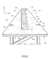
- FIG. 2 is a schematic perspective view that illustrates a forming tool according to one embodiment of the invention
- FIG. 3 is an axial cross-sectional view of the tool in FIG. 2 ;
- FIG. 4 is a schematic perspective view that illustrates a forming tool according to a further embodiment of the invention.
- FIGS. 5A to 5G illustrate schematically a sequence of a procedure for the forming of H-beams, making use of mandrels for forming with a distributed perforation
- FIG. 6 is a perspective view of an end part of a forming tool.
- a forming tool is indicated overall by 21 .
- the tool 21 comprises a forming mandrel 22 having a rigid body 23 of substantially rectangular or slightly trapezoidal cross-section, extending longitudinally along an axis A parallel to a geometric axis x.
- the rigid body 23 is solidly fixed to a rigid plane plate 40 , having a preferably smooth surface 42 which extends all around the mandrel 22 .
- the mandrel 22 has three outer perimeter faces 24 , 26 , 27 , besides an interface surface 25 with which the mandrel 22 is solidly attached to the rigid plane plate 40 .
- the outer plane face 24 of the mandrel 22 has a distributed perforation 34 , comprising a plurality of holes 36 that run in a direction transverse to the longitudinal axis A of the mandrel 22 .
- the holes 36 are preferably distributed in a uniform manner over the surface 24 of the mandrel 22 .
- the diameter of the holes 36 which open onto the outer plane surface 24 can vary according to the requirements. Optimum results, in terms of efficacy and of quality of the surface formed have been achieved with holes 36 having a diameter of around 3 mm. Preferably, the diameter of the holes 36 is in the range between 2 mm and 4 mm.
- a plurality of secondary ducts 38 puts the holes 36 into communication with a primary duct 32 which runs along the inside of the mandrel 22 ; in the embodiment illustrated, the primary duct 32 runs along an axis parallel or coinciding with the longitudinal axis A of the mandrel 22 .
- the primary duct 32 can be supplied, alternately, by two external sources (not shown), respectively a source of vacuum and a source of compressed air.
- the connection between the external sources and the primary duct 32 can be made by means of an inlet/outlet connector 41 disposed at one end of the primary duct 32 ( FIG. 6 ).
- the connector 41 may for convenience be of the automatic quick-connect type.
- the primary duct 32 has one outlet 32 a on a front face 28 of the mandrel 22 , into which outlet 32 a the connector 41 can be inserted.
- the primary duct 32 together with the secondary ducts 38 , forms a series of passages, indicated overall by the number 31 , which establish a fluid communication between the distributed perforation 34 and the inlet/outlet connector 41 .
- the primary duct 32 can have two outlets, respectively on the front face 28 and on an opposing rear face 30 , into which outlets two inlet/outlet connectors 41 can respectively be inserted, for example two automatic quick-connects.
- the primary duct 32 does not have any outlets on either the front face 28 or on the rear face 30 , but achieves fluid communication with the external sources of vacuum and/or compressed air by means of one or more outlets passing through the rigid plane plate 40 .
- the outlets are oriented in a transverse direction with respect to the longitudinal axis A of the mandrel 22 .
- the distributed perforation 34 is formed, other than on the plane outer face 24 , also on the lateral outer faces 26 .
- the distributed perforation 34 can be formed only on the lateral outer faces 26 , rather than on the plane outer face 24 .
- the mandrel 50 has a rigid box-like structure 51 , comprising five perimeter walls 52 , 53 , 54 , 55 , 56 that bound an internal hollow chamber 62 .
- the walls 54 , 55 , 56 have respective outer faces 54 a , 55 a , 56 a .
- the internal hollow chamber 62 forms a fluid communication between the external sources of vacuum and/or compressed air and a distributed perforation 58 that comprises a plurality of through-holes 60 formed through the plane wall 56 .
- the through-holes 60 may be formed through both the plane wall 56 and also through the lateral walls 54 , 55 .
- the through-holes 60 are formed through at least one of the walls 54 , 55 , 56 , so as to open onto at least one of the outer faces 54 a , 55 a , 56 a.
- the mandrel may indifferently have a rectangular cross-section, with two opposing parallel faces 54 a and 55 a , or else trapezoidal, with two opposing faces 54 a and 55 a slightly converging towards the outer face 56 a .
- the outer face 56 a forms an angle greater than or equal to 90° with each of the two opposing faces 54 a and 55 a .
- the method is carried out starting from two C-section beams 10 , 16 each having a cross-section substantially in the shape of a C.
- the C-section beams 10 , 16 are made from fibre-reinforced polymerizable thermosetting composite material, typically carbon fibre.
- the C-section beams 10 , 16 are preformed and non-polymerized (uncured).
- Each C-section beam is applied on three consecutive perimeter faces 24 , 26 , 27 , 24 ′, 26 ′, 27 ′ of a first mandrel 22 and of a second mandrel 22 ′; the perimeter faces comprise a planar face 24 , 24 ′ and two lateral faces 26 , 27 , 26 ′, 27 ′ ( FIG. 5A ).
- An external source of vacuum (not shown) can be connected to the connector 41 and put into fluid communication with the distributed perforation 34 of the first mandrel, exerting a suction force that holds the C-section beam 10 onto the mandrel 22 ( FIG. 5B ).
- an analogous suction force (not necessarily having the same intensity) may also be applied to the second mandrel 22 ′; the aforementioned suction force may optionally also be applied to the second mandrel 22 ′ in the steps that will be described hereinbelow.
- the first mandrel 22 is lifted in a direction substantially perpendicular to the direction of the longitudinal axis A of the mandrel 22 ( FIG. 5C ). Subsequently, the first mandrel 22 may be translated horizontally in order to end up superposed onto the second mandrel 22 ′ ( FIG. 5D ), in such a manner that the longitudinal axes A, A′ of the two mandrels 22 , 22 ′ are lying in the same vertical plane.
- the lifting and translation operations described above may conveniently be carried out by a travelling crane equipped with a pick-up system comprising a series of suction cups connected to a suction system, and a series of extendable and retractable pins which are engaged into centering holes 44 , arranged for this purpose on the surface 42 of the rigid plane plate 40 .
- a travelling crane with a pick-up system designed for this purpose is known from WO 2008/155720 A2.
- the first mandrel 22 which is in a raised position along the z axis with respect to the second mandrel 22 ′, is rotated by 180° about its own longitudinal axis A ( FIG. 5E ).
- the suction force exerted by the external source of the vacuum on the C-section beam 10 via the distributed perforation 34 , holds the C-section beam 10 on the mandrel 22 even in an upside-down position.
- the backs 14 a , 20 a of the webs 14 , 20 of the two C-section beams 10 , 16 end up facing each other and spaced apart.
- the mandrels 22 , 22 ′ are brought towards one another until the backs 14 a , 20 a of the webs 14 , 20 of the two C-section beams 10 , 16 come into contact ( FIG. 5F ).
- This step can be conveniently carried out by lowering the first (upper) mandrel 22 onto the second (lower) mandrel 22 ′.
- the step for juxtaposing and contacting the backs 14 a , 20 a of the webs 14 , 20 of the two C-section beams 10 , 16 may be followed by a step of applying filling elements of the type indicated by 22 in FIG. 1 along two longitudinal recesses which are located in the connection areas between the webs 14 , 20 and the flanges 12 , 13 , 18 , 19 of the C-section beams 10 , 16 .
- the assembly of the two mandrels 22 , 22 ′ and of the respective coupled C-section beams 10 , 16 can thus be transferred as a single unit into a final compacting station (not shown), where the assembled H-beam 5 , formed from the coupled C-section beams 10 , 16 (and, potentially, from the filling elements 22 ), is subjected to the action of the vacuum.
- the suction force can be maintained on one or both the mandrels 22 , 22 ′ so as to guarantee the stability of positioning of the H-beam 5 .
- the operations for compaction with hot forming are known per se in the technology and are not described here.
- the first mandrel 22 is connected to the external source of compressed air which, acting on the H-beam 5 via the distributed perforation 34 , facilitates the removal of the H-beam 5 from the first mandrel 22 .
- the first mandrel 22 is taken away ( FIG. 5E ).
- the second mandrel 22 ′ is also pressurized, in such a manner that the consequent expulsion force assists the removal of the H-beam 5 also from the second mandrel 22 ′. In this way, both the speed of processing and the quality of the manufacturing are guaranteed.
- vacuum and pressure of the air to be applied to the process can respectively be around 700 mmHg (93.3 kPa) and around 2000 mmHg (266.6 kPa). These values are indicative and not to be taken as limiting.
- the two mandrels 22 , 22 ′ are both rotated by 90° with respect to their own longitudinal axes A, A′, according to appropriate directions of rotation so as to bring the backs 14 a , 20 a of the webs 14 , 20 of the two C-section beams 10 , 16 into positions facing each other and spaced apart in a substantially horizontal direction y.
- the backs 14 a , 20 a of the webs 14 , 20 of the two C-section beams 10 , 16 are therefore brought together until they come into mutual contact.
- the filling elements 22 may be applied to the non-polymerized H-beam 5 thus obtained, according to the procedure previously described.
Landscapes
- Engineering & Computer Science (AREA)
- Mechanical Engineering (AREA)
- Chemical & Material Sciences (AREA)
- Composite Materials (AREA)
- Textile Engineering (AREA)
- Moulding By Coating Moulds (AREA)
- Moulds For Moulding Plastics Or The Like (AREA)
Applications Claiming Priority (3)
| Application Number | Priority Date | Filing Date | Title |
|---|---|---|---|
| ITTO2013A1020 | 2013-12-13 | ||
| IT001020A ITTO20131020A1 (it) | 2013-12-13 | 2013-12-13 | Attrezzo e procedimento per la formatura e l'assemblaggio di longheroni di materiale composito |
| ITTO2013A001020 | 2013-12-13 |
Publications (2)
| Publication Number | Publication Date |
|---|---|
| US20150165699A1 US20150165699A1 (en) | 2015-06-18 |
| US9878505B2 true US9878505B2 (en) | 2018-01-30 |
Family
ID=50159431
Family Applications (1)
| Application Number | Title | Priority Date | Filing Date |
|---|---|---|---|
| US14/567,584 Active 2036-03-07 US9878505B2 (en) | 2013-12-13 | 2014-12-11 | Tool and a method for forming and assembling beams of composite material |
Country Status (4)
| Country | Link |
|---|---|
| US (1) | US9878505B2 (de) |
| EP (1) | EP2886312B1 (de) |
| ES (1) | ES2759223T3 (de) |
| IT (1) | ITTO20131020A1 (de) |
Families Citing this family (4)
| Publication number | Priority date | Publication date | Assignee | Title |
|---|---|---|---|---|
| US9211679B1 (en) | 2013-05-03 | 2015-12-15 | The Boeing Company | Systems and methods of forming a skin for a composite structure and composite structures including the same |
| US20160236425A1 (en) * | 2015-02-13 | 2016-08-18 | The Boeing Company | Roughened tool surfaces for thermoset composite layups and systems and methods including the same |
| US9663247B2 (en) | 2015-02-27 | 2017-05-30 | The Boeing Company | Systems, methods, and vacuum chucks for transferring flexible elongate bodies |
| US10005234B2 (en) | 2015-10-29 | 2018-06-26 | The Boeing Company | Devices, systems, and methods for compacting a charge of composite material across an edge |
Citations (8)
| Publication number | Priority date | Publication date | Assignee | Title |
|---|---|---|---|---|
| US4475976A (en) * | 1983-12-23 | 1984-10-09 | The Boeing Company | Method and apparatus for forming composite material articles |
| FR2614387A1 (fr) * | 1987-04-27 | 1988-10-28 | Pechiney Aluminium | Raccord automatique pour circuit d'alimentation en fluide d'engins mobiles |
| US5092954A (en) | 1989-04-14 | 1992-03-03 | Gurit-Essex Ag | Devices for mechanically applying a flexible multi-layer body member which is adherent on its one side to the surface of a workpiece |
| US20060108057A1 (en) | 2004-11-24 | 2006-05-25 | The Boeing Company | Flexible mandrel for highly contoured composite stringer |
| US20070251641A1 (en) | 2006-04-28 | 2007-11-01 | Airbus Espana, S.L. | Tool and process for manufacturing long pieces of composite material |
| WO2008155720A2 (en) | 2007-06-18 | 2008-12-24 | Alenia Aeronautica S.P.A. | Method and equipment for forming and assembling uncured spars for the horizontal stabilizers of aircraft |
| US20110005666A1 (en) * | 2008-04-23 | 2011-01-13 | Airbus Operations Limited | Method of tape laying of thermoplastic composite materials |
| WO2011128110A1 (de) * | 2010-04-16 | 2011-10-20 | Compositence Gmbh | Vorrichtung und verfahren zum herstellen von fasergelegen |
-
2013
- 2013-12-13 IT IT001020A patent/ITTO20131020A1/it unknown
-
2014
- 2014-12-11 US US14/567,584 patent/US9878505B2/en active Active
- 2014-12-12 ES ES14197584T patent/ES2759223T3/es active Active
- 2014-12-12 EP EP14197584.7A patent/EP2886312B1/de active Active
Patent Citations (9)
| Publication number | Priority date | Publication date | Assignee | Title |
|---|---|---|---|---|
| US4475976A (en) * | 1983-12-23 | 1984-10-09 | The Boeing Company | Method and apparatus for forming composite material articles |
| FR2614387A1 (fr) * | 1987-04-27 | 1988-10-28 | Pechiney Aluminium | Raccord automatique pour circuit d'alimentation en fluide d'engins mobiles |
| US5092954A (en) | 1989-04-14 | 1992-03-03 | Gurit-Essex Ag | Devices for mechanically applying a flexible multi-layer body member which is adherent on its one side to the surface of a workpiece |
| US20060108057A1 (en) | 2004-11-24 | 2006-05-25 | The Boeing Company | Flexible mandrel for highly contoured composite stringer |
| US20070251641A1 (en) | 2006-04-28 | 2007-11-01 | Airbus Espana, S.L. | Tool and process for manufacturing long pieces of composite material |
| WO2008155720A2 (en) | 2007-06-18 | 2008-12-24 | Alenia Aeronautica S.P.A. | Method and equipment for forming and assembling uncured spars for the horizontal stabilizers of aircraft |
| US20110005666A1 (en) * | 2008-04-23 | 2011-01-13 | Airbus Operations Limited | Method of tape laying of thermoplastic composite materials |
| WO2011128110A1 (de) * | 2010-04-16 | 2011-10-20 | Compositence Gmbh | Vorrichtung und verfahren zum herstellen von fasergelegen |
| US20130174969A1 (en) * | 2010-04-16 | 2013-07-11 | Compositence Gmbh | Apparatus and Method for Manufacturing Fibre Layers |
Non-Patent Citations (2)
| Title |
|---|
| European Search Report for corresponding European Patent Application No. 14197584 dated May 13, 2015. |
| Italian Search Report for corresponding Italian Patent Application No. TO2013A001020 dated Aug. 22, 2014. |
Also Published As
| Publication number | Publication date |
|---|---|
| EP2886312A1 (de) | 2015-06-24 |
| ITTO20131020A1 (it) | 2015-06-14 |
| ES2759223T3 (es) | 2020-05-08 |
| US20150165699A1 (en) | 2015-06-18 |
| EP2886312B1 (de) | 2019-11-06 |
Similar Documents
| Publication | Publication Date | Title |
|---|---|---|
| US9878505B2 (en) | Tool and a method for forming and assembling beams of composite material | |
| US8668800B2 (en) | Method of manufacturing hollow composite parts with in situ formed internal structures | |
| US9604417B2 (en) | Method for making contoured composite stiffeners | |
| US8287790B2 (en) | Method for manufacturing beams of fiber-reinforced composite material | |
| CN103158888A (zh) | 生产大型集成翼型的方法和装置 | |
| US20140090528A1 (en) | Method and device for transporting a fiber contour cut out from a planar woven fabric in the course of producing fiber-reinforced plastic molded parts | |
| CN113524721B (zh) | 一种复合材料t型加筋壁板共固化成型装置及使用方法 | |
| CN108248071B (zh) | 口形梁的制造方法 | |
| EP2067596B1 (de) | Verfahren und Vorrichtung zur Herstellung eines Gegenstandes mit einem leeren Raum | |
| WO2014200675A1 (en) | Method and apparatus for fabricating composite stringers | |
| RU2507071C1 (ru) | Способ получения трехслойного полимерного композиционного материала (тспкм) | |
| CA2289292A1 (en) | Apparatus and method for installing a leading-edge sheath onto a helicopter main rotor blade subassembly | |
| CN112372903B (zh) | 织物增强型橡胶管硫化成型工艺 | |
| CN205112423U (zh) | 车用碳纤维复合材料帽型梁制备模具 | |
| CN107553949A (zh) | 一种气室橡胶隔膜制作方法及其设备 | |
| TWI603858B (zh) | A core-stock material, a core-molding device, and a method of manufacturing the composite rim using the core-type device | |
| CN211416572U (zh) | 一种单曲面三明治复合板 | |
| JP2022125261A (ja) | 複合材料構造物の製造方法 | |
| CN116423879B (zh) | 一种复合材料环向t形加强框的成型模具及其制备方法 | |
| CN113263754A (zh) | 用于制造飞行器机翼的由复合材料制成的中央沉箱的方法 | |
| US20250065580A1 (en) | Repair device, repair system, and repair method | |
| CN223849299U (zh) | 一种机械模块化用稳固型拼接结构及机器人 | |
| CN110816017A (zh) | 一种单曲面三明治复合板及其模具及其成型工艺 | |
| CN117227046A (zh) | 复合材料一体成型装置及方法 | |
| CN117799194A (zh) | 碳纤工件外凸铰链孔成型模具及成型方法 |
Legal Events
| Date | Code | Title | Description |
|---|---|---|---|
| AS | Assignment |
Owner name: ALENIA AERMACCHI S.P.A., ITALY Free format text: ASSIGNMENT OF ASSIGNORS INTEREST;ASSIGNORS:CARRETTI, DANIELA;IAGULLI, GIANNI;LEMBO, GIANPIERO;AND OTHERS;REEL/FRAME:035129/0593 Effective date: 20150213 |
|
| STCF | Information on status: patent grant |
Free format text: PATENTED CASE |
|
| MAFP | Maintenance fee payment |
Free format text: PAYMENT OF MAINTENANCE FEE, 4TH YEAR, LARGE ENTITY (ORIGINAL EVENT CODE: M1551); ENTITY STATUS OF PATENT OWNER: LARGE ENTITY Year of fee payment: 4 |
|
| MAFP | Maintenance fee payment |
Free format text: PAYMENT OF MAINTENANCE FEE, 8TH YEAR, LARGE ENTITY (ORIGINAL EVENT CODE: M1552); ENTITY STATUS OF PATENT OWNER: LARGE ENTITY Year of fee payment: 8 |