US986925A - Insect-destroyer. - Google Patents
Insect-destroyer. Download PDFInfo
- Publication number
- US986925A US986925A US49046409A US1909490464A US986925A US 986925 A US986925 A US 986925A US 49046409 A US49046409 A US 49046409A US 1909490464 A US1909490464 A US 1909490464A US 986925 A US986925 A US 986925A
- Authority
- US
- United States
- Prior art keywords
- insect
- tank
- destroyer
- liquid
- vehicle
- Prior art date
- Legal status (The legal status is an assumption and is not a legal conclusion. Google has not performed a legal analysis and makes no representation as to the accuracy of the status listed.)
- Expired - Lifetime
Links
- 239000007788 liquid Substances 0.000 description 8
- 238000010276 construction Methods 0.000 description 5
- 241000238631 Hexapoda Species 0.000 description 4
- 238000005507 spraying Methods 0.000 description 3
- 230000005484 gravity Effects 0.000 description 1
- 239000002917 insecticide Substances 0.000 description 1
- 238000000034 method Methods 0.000 description 1
- 238000012856 packing Methods 0.000 description 1
- 239000007921 spray Substances 0.000 description 1
Images


Classifications
-
- A—HUMAN NECESSITIES
- A01—AGRICULTURE; FORESTRY; ANIMAL HUSBANDRY; HUNTING; TRAPPING; FISHING
- A01M—CATCHING, TRAPPING OR SCARING OF ANIMALS; APPARATUS FOR THE DESTRUCTION OF NOXIOUS ANIMALS OR NOXIOUS PLANTS
- A01M7/00—Special adaptations or arrangements of liquid-spraying apparatus for purposes covered by this subclass
- A01M7/0025—Mechanical sprayers
- A01M7/0032—Pressure sprayers
- A01M7/0035—Pressure sprayers mounted on a frame and guided by hand; Spray barrow
-
- Y—GENERAL TAGGING OF NEW TECHNOLOGICAL DEVELOPMENTS; GENERAL TAGGING OF CROSS-SECTIONAL TECHNOLOGIES SPANNING OVER SEVERAL SECTIONS OF THE IPC; TECHNICAL SUBJECTS COVERED BY FORMER USPC CROSS-REFERENCE ART COLLECTIONS [XRACs] AND DIGESTS
- Y10—TECHNICAL SUBJECTS COVERED BY FORMER USPC
- Y10S—TECHNICAL SUBJECTS COVERED BY FORMER USPC CROSS-REFERENCE ART COLLECTIONS [XRACs] AND DIGESTS
- Y10S43/00—Fishing, trapping, and vermin destroying
- Y10S43/90—Liquid insecticide sprayer
Definitions
- This invention relates to insect destroyers andmore particularly to spraying devices of the vehicle type whereby a plurality of rows of plants can be sprayed as the vehicle is driven 'through the field
- the invention has for one of its objects to the plants, and whereby two or more rows can be sprayed at the same time, the liquid being drawn from auxiliary tanks that are connected with a common tank in which is contained a continuously-operated agitator.
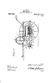
- Figure 1 is a plan view of the machine.
- Fig. 2 is a longitudinal section thereof
- Fig. 3 is a transverse section.
- Figs. 4. and 5 are detail viewsof the pitman connections between thelpump plungers and the crank I shaft.
- A designates the frame of the vehicle which may be of any approved construction and mounted on pumps, and on the ends of the axle are tracinstance, is conslsting 0 an axle 1 that has its central portion arched to accommodate the auxiliary tanks and tion wheels 2;
- the vehicle in the present rqvided with. a draft device f a' tongue 3 and whiumbletree 4.
- a seat 5 for the driver, the seat being conveniently arranged Specification of LettersPatent. ,PatentedMar, 14, 1911 Application filed April 17, 1909. Serial No. 490,464.
- valves for controlling the flow of the spraying liquid 'can' be manipulated.
- a transversely-extending reservoir or main tank 6 Arranged at the front of .the vehicle frame is a transversely-extending reservoir or main tank 6 that is held in place by straps 7 and in the top of this tank is a fillingopening 8 which is normally closed by a cap 9.
- a central shaft 10 Arranged within the tank is a central shaft 10 that carries a plurality'of agitating arms [1 whereby the liquid will be continuously agitated" during the move- 1ment of the vehicle, tliere being powertransmitting devices between the wheels 2 and shaft 10, which devices are in the form of sprocket chains 13 that pass around sprocket wheels 14 and 15 on the hubs of wheelsfl and ends'of the shafts 10, respectively.
- the spraying machine is igned to spray two rows of plants at a time and for this purpose two sets of pumps are employed which receive liquid from auxiliary tanks 16 arranged in brackets 17 under the middle portion of the axle and extending longitudinally of the Vehicle.
- each auxil “iary tank 16 is a cylinders 20 supported on the brackets 17 and in each pump is a piston 21 that has a rod 22 extending out of the forward end of the tank through a packing box 23, and theseflplunger rods are connected with a crank shaft 24 that is supported in brackets 25 at the front end of the machine.
- the crank shaft is provided at its ends with air of parallel pump sprocket wheels 26 around -.which pass sprocket chains 27 that are driven by sprocket wheels 28 on the hubs of the traction wheels 2,.
- a branch supply pipe 29 havin check valves 30 which permit the liquid to ow from the auxiliary tank to 'the respective pumps and this [fipe is provided with a hand-controlled valve 31 whereby either auxiliary tank and adjacent pumps can'be closed, as for instance, when only one row of plants is to be sprayed.
- - Attached to the rear ends of the pump cylinders aredischarge pipes 32 that have check valves 33 and these pipes areconnected together by a union 34, and attached transversely through the row and the other arallel there:
- each piston rod and crank consists of two sections a and b, the section a being in the form of a rod pivotally connected at its rear end 37' with the,
Landscapes
- Engineering & Computer Science (AREA)
- Life Sciences & Earth Sciences (AREA)
- Mechanical Engineering (AREA)
- Insects & Arthropods (AREA)
- Pest Control & Pesticides (AREA)
- Wood Science & Technology (AREA)
- Zoology (AREA)
- Environmental Sciences (AREA)
- Catching Or Destruction (AREA)
Description
E. R. LYON. INSECT DESTROYER. APPLICATION FILED APB.17, 1909.
986,925, Patented Mar. 14, 1911.
3 SHEETS-SHEET 1.
ww u ZZizwizfllywz, I wwaym WW E. R. LYON.
I INSECT DESTROYER. APPLIOATIOH mum APB.17, 1909.
Patented Mar. 14, 1911.
3 BHEETB-SHEET 2.
' ZZZVZ/ZZZZL I innl ill-I Ill-ll.
Guam;
E. R. LYON'. INSECT DBSTROYEB. APPLIOATIOIF F ILED APR 17, 1909.
Patented Mar. 14, 1911.
3 SHEETS-SHEET 3.
UNITED STATES; PATENT OFFICE.
EDWIN 12.. LYON, or QUEEN, TERRITORY or NEW MEXICO.
' INSECT-DESTROYER.
To all whom it may concern:
Be it known that I, EDWIN R. LYN,.a citizen of the United States, residing at Queen, in the county of Eddy and Territory,
of New Mexico, have invented new and use- ,ful Improvements in Insect-Destroyers, of
which. the following is a specification;
' improve and simplify the construction and This invention relates to insect destroyers andmore particularly to spraying devices of the vehicle type whereby a plurality of rows of plants can be sprayed as the vehicle is driven 'through the field The invention has for one of its objects to the plants, and whereby two or more rows can be sprayed at the same time, the liquid being drawn from auxiliary tanks that are connected with a common tank in which is contained a continuously-operated agitator.
With these objects in view and others, as
. will appear as the description proceeds, the
hereinafter and set forth with particularly. in the claim appended hereto.
invention comprises the various novel features 6f construction and arrangement of parts which, will be more fully described In the accompanying. drawings, which illustrate-one.embodiment of the invention, Figure 1 is a plan view of the machine. Fig. 2 is a longitudinal section thereof Fig. 3 is a transverse section. Figs. 4. and 5 are detail viewsof the pitman connections between thelpump plungers and the crank I shaft.
Similar reference characters are employed I to designate corresponding parts through-.
out the views. Referring to the drawings, A designates the frame of the vehicle which may be of any approved construction and mounted on pumps, and on the ends of the axle are tracinstance, is conslsting 0 an axle 1 that has its central portion arched to accommodate the auxiliary tanks and tion wheels 2; The vehicle, in the present rqvided with. a draft device f a' tongue 3 and whiiiletree 4. Arranged on the axle is a seat 5 for the driver, the seat being conveniently arranged Specification of LettersPatent. ,PatentedMar, 14, 1911 Application filed April 17, 1909. Serial No. 490,464. I
so that the valves for controlling the flow of the spraying liquid 'can' be manipulated.
Arranged at the front of .the vehicle frame is a transversely-extending reservoir or main tank 6 that is held in place by straps 7 and in the top of this tank is a fillingopening 8 which is normally closed by a cap 9. Arranged within the tank is a central shaft 10 that carries a plurality'of agitating arms [1 whereby the liquid will be continuously agitated" during the move- 1ment of the vehicle, tliere being powertransmitting devices between the wheels 2 and shaft 10, which devices are in the form of sprocket chains 13 that pass around sprocket wheels 14 and 15 on the hubs of wheelsfl and ends'of the shafts 10, respectively. .In the present instance, the spraying machine is igned to spray two rows of plants at a time and for this purpose two sets of pumps are employed which receive liquid from auxiliary tanks 16 arranged in brackets 17 under the middle portion of the axle and extending longitudinally of the Vehicle.
Between the main tank- 7 and each auxil "iary tank is a supply pipe 18in such a manner that liquid will flow from the former .'to the latter by gravity, and in each supply pipe is a-valve 19 whereby liquid can be supplied to either set of pumps. vUnder each auxiliary tank 16is a cylinders 20 supported on the brackets 17 and in each pump is a piston 21 that has a rod 22 extending out of the forward end of the tank through a packing box 23, and theseflplunger rods are connected with a crank shaft 24 that is supported in brackets 25 at the front end of the machine. The crank shaft is provided at its ends with air of parallel pump sprocket wheels 26 around -.which pass sprocket chains 27 that are driven by sprocket wheels 28 on the hubs of the traction wheels 2,. Between each auxiliary tank 16 and adjacent pair of pumps is a branch supply pipe 29 havin check valves 30 which permit the liquid to ow from the auxiliary tank to 'the respective pumps and this [fipe is provided with a hand-controlled valve 31 whereby either auxiliary tank and adjacent pumps can'be closed, as for instance, when only one row of plants is to be sprayed.- Attached to the rear ends of the pump cylinders aredischarge pipes 32 that have check valves 33 and these pipes areconnected together by a union 34, and attached transversely through the row and the other arallel there:
the invention appertains, and while I have- With so that the plants will e effectively sprayed by the insecticide liquid. ''Thepitman connection between each piston rod and crank consists of two sections a and b, the section a being in the form of a rod pivotally connected at its rear end 37' with the,
plunger rod and having its forward end formed into a spherical enlargement or ball 37 which is disposed in a socket or opening 38 in the section b, there being a slot 'extending r'earwardly from the socket to present parallel -members 39 between which the rod a extends. The rod section is-held in place with respectvto the section b by a bolt 40 that extends through the members 39 and also through a slot 41 in the rod section a. By this construction, the connecting bolt 40 is subjected to-no strain, since the enlargement 37 bears against, the walls of the socket 38 at a, when the pump piston ismoved forwardlyand bears against the wall of the socket at (2 during the rear strokes ofthe piston. The section b of the pitmanisprovided with a bearing 42 for receiving the crank pin 43 of the shaft 24. F
From the foregoing description, taken in connection with the accompanying drawings, the advantages of the construction and of the method of operation will be readiig apparent to those skilled in the art to whi described' the principle of operation of the invention, together with the apparatus which I now consider to be the best embodiment thereof, I desire to have it understood that the apparatus shown is merely illustrative, and that such changes may be made scope of the extending horizontally and disposed longitudinally of the machine, acommon means for rigidly supporting the cylinders and auxiliary tanks on the said frame, and a s raying device connected with the discharge of each pump.
In testimony whereof I afiix my signature in presence of twowitnesses.
CARL ALFORD, C. A. MCOLURE.
Priority Applications (1)
| Application Number | Priority Date | Filing Date | Title |
|---|---|---|---|
| US49046409A US986925A (en) | 1909-04-17 | 1909-04-17 | Insect-destroyer. |
Applications Claiming Priority (1)
| Application Number | Priority Date | Filing Date | Title |
|---|---|---|---|
| US49046409A US986925A (en) | 1909-04-17 | 1909-04-17 | Insect-destroyer. |
Publications (1)
| Publication Number | Publication Date |
|---|---|
| US986925A true US986925A (en) | 1911-03-14 |
Family
ID=3055265
Family Applications (1)
| Application Number | Title | Priority Date | Filing Date |
|---|---|---|---|
| US49046409A Expired - Lifetime US986925A (en) | 1909-04-17 | 1909-04-17 | Insect-destroyer. |
Country Status (1)
| Country | Link |
|---|---|
| US (1) | US986925A (en) |
-
1909
- 1909-04-17 US US49046409A patent/US986925A/en not_active Expired - Lifetime
Similar Documents
| Publication | Publication Date | Title |
|---|---|---|
| CN201781887U (en) | Self-propelled high-clearance spray-lance spraying machine | |
| CN102948409B (en) | Hydraulic self-propelled cotton field high-gap pesticide spray vehicle | |
| US986925A (en) | Insect-destroyer. | |
| CN204518984U (en) | A kind of new-type spraying machine | |
| US1416065A (en) | Spraying apparatus | |
| CN206227442U (en) | A kind of field multimode pesticide spray truck | |
| CN104126355B (en) | Overhead farm land cultivator | |
| US1668157A (en) | Beet harvester | |
| US1374274A (en) | Sprayer attachment | |
| US912261A (en) | Sprayer. | |
| CN201630161U (en) | Three-wheel rear-driving self-propelled type high-stalk crop spraying boom spraying machine | |
| US2836112A (en) | Hitch attachment for a powered vehicle | |
| US498696A (en) | Sprayer | |
| US805689A (en) | Poison-distributer for plants. | |
| US349087A (en) | Plant and tree culture apparatus | |
| US1307498A (en) | Rail-oiling machine | |
| DE102009044445A1 (en) | spraying device | |
| CN112425588A (en) | Eminence laxative machine | |
| US1071486A (en) | Cotton-spray. | |
| US1543021A (en) | Spraying machine | |
| US2565143A (en) | Material spreader having a vibratory hopper bottom | |
| US1287578A (en) | Spraying-machine. | |
| US1051202A (en) | Tender for traction-engines. | |
| US1520854A (en) | Boll-weevil-spraying machine | |
| US1751039A (en) | Spraying machine |