US9866439B2 - Communications system, management apparatus, and communication setting method - Google Patents
Communications system, management apparatus, and communication setting method Download PDFInfo
- Publication number
- US9866439B2 US9866439B2 US14/607,119 US201514607119A US9866439B2 US 9866439 B2 US9866439 B2 US 9866439B2 US 201514607119 A US201514607119 A US 201514607119A US 9866439 B2 US9866439 B2 US 9866439B2
- Authority
- US
- United States
- Prior art keywords
- communication
- setting information
- setting
- tlv
- config
- Prior art date
- Legal status (The legal status is an assumption and is not a legal conclusion. Google has not performed a legal analysis and makes no representation as to the accuracy of the status listed.)
- Expired - Fee Related, expires
Links
Images




Classifications
-
- H—ELECTRICITY
- H04—ELECTRIC COMMUNICATION TECHNIQUE
- H04L—TRANSMISSION OF DIGITAL INFORMATION, e.g. TELEGRAPHIC COMMUNICATION
- H04L41/00—Arrangements for maintenance, administration or management of data switching networks, e.g. of packet switching networks
- H04L41/08—Configuration management of networks or network elements
- H04L41/0803—Configuration setting
- H04L41/084—Configuration by using pre-existing information, e.g. using templates or copying from other elements
- H04L41/0846—Configuration by using pre-existing information, e.g. using templates or copying from other elements based on copy from other elements
-
- H—ELECTRICITY
- H04—ELECTRIC COMMUNICATION TECHNIQUE
- H04L—TRANSMISSION OF DIGITAL INFORMATION, e.g. TELEGRAPHIC COMMUNICATION
- H04L41/00—Arrangements for maintenance, administration or management of data switching networks, e.g. of packet switching networks
- H04L41/08—Configuration management of networks or network elements
- H04L41/0803—Configuration setting
- H04L41/0806—Configuration setting for initial configuration or provisioning, e.g. plug-and-play
Definitions
- the embodiments discussed herein are related to communication systems, management apparatuses, and communication setting methods.
- a communication system which includes a server, a storage apparatus, and the like and to which a plurality of terminal apparatuses is connected.
- a wire connection work and a setting work by an administrator are performed.
- the wire connection work and setting work by an administrator are supposed to be manually performed by the administrator, and once the administrator makes an error in setting, terminal apparatuses are unable to communicate with each other.
- the administrator may need to check the whole setting once an error occurs in the setting, and thus the time and effort for an administrator to spend on the setting work may become huge.
- the setting differs with communications protocols and the setting work is complicated.
- a certain scale of storage system may have a switch with 100 ports. In a communication system having such a switch, an administrator may manually set as much as 1000 commands when the setting per port needs ten commands.
- a communication system including: a first communication apparatus; a second communication apparatus; a relay apparatus which relays communication between the first communication apparatus and the second communication apparatus; and a management apparatus which manages a setting of the relay apparatus
- the first communication apparatus includes: a first setting information notification unit that notifies the management apparatus via the relay apparatus of first setting information including a communication setting of the first communication apparatus; and a setting update unit that updates the communication setting with third setting information received from the management apparatus
- the management apparatus includes: a setting information generation unit that generates the third setting information from the first setting information and second setting information that is preliminarily stored in a setting information storage unit; a communication confirmation unit that confirms communication based on the third setting information between the first communication apparatus and the second communication apparatus; and a second setting information notification unit that notifies the relay apparatus, the first communication apparatus via the relay apparatus, and the second communication apparatus via the relay apparatus of the third setting information, after confirmation of the communication, wherein the relay apparatus includes a setting update unit that updates the communication setting
- FIG. 1 illustrates an example of the configuration of a communication system of a first embodiment
- FIG. 2 illustrates an example of the connection configuration of a storage system of a second embodiment
- FIG. 3 illustrates an example of the functional configuration of the storage system of the second embodiment
- FIG. 4 illustrates an example of the setting sequence of the second embodiment
- FIG. 5 illustrates an example of the hardware configuration of a management server of the second embodiment
- FIG. 6 illustrates a flowchart of TLV notification processing of the second embodiment
- FIG. 7 illustrates an example (Part 1) of Config Profile TLV of the second embodiment
- FIG. 8 illustrates an example (Part 2) of the Config Profile TLV of the second embodiment
- FIG. 9 illustrates an example (Part 3) of the Config Profile TLV of the second embodiment
- FIG. 10 illustrates a flowchart of TLV authentication processing of the second embodiment
- FIG. 11 illustrates a flowchart of access control verification processing 1 of the second embodiment
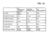
- FIG. 12 illustrates an example of merging Config Profile TLV's of the second embodiment
- FIG. 13 illustrates an example of merging Config Profile TLV's of the second embodiment
- FIG. 14 illustrates a flowchart of access control verification processing 2 of the second embodiment
- FIG. 15 illustrates a flowchart of access control verification processing 3 of the second embodiment
- FIG. 16 illustrates a flowchart of setting determination processing of the second embodiment
- FIG. 17 illustrates a flowchart of setting notification processing of the second embodiment
- FIG. 18 illustrates a flowchart of setting update processing 1 of the second embodiment
- FIG. 19 illustrates a flowchart of setting update processing 2 of the second embodiment.
- FIG. 20 illustrates an example of changing the configuration of the storage system of the second embodiment.
- FIG. 1 illustrates an example of the configuration of the communication system of the first embodiment.
- a communication system 1 includes a first communication apparatus 2 , a second communication apparatus 3 , a relay apparatus 4 , and a management apparatus 5 .
- the first communication apparatus 2 and second communication apparatus 3 may communicate with each other via the relay apparatus 4 that relays communication between the first communication apparatus 2 and the second communication apparatus 3 .
- the management apparatus 5 manages the setting of each of the first communication apparatus 2 , second communication apparatus 3 , and relay apparatus 4 .
- the communication system 1 is a storage system, where the first communication apparatus 2 or the second communication apparatus 3 is a business server or a storage apparatus, the relay apparatus 4 is a switch, and the management apparatus 5 is a management server, for example.
- the first communication apparatus 2 is the apparatus serving as a starting point of changing the setting.
- the first communication apparatus 2 includes a first setting information notification unit 2 a and a setting update unit 2 b .
- the first setting information notification unit 2 a notifies the management apparatus 5 via the relay apparatus 4 of first setting information 6 including the communication setting of the first communication apparatus 2 .
- the notification of the first setting information 6 to the management apparatus 5 is the starting point of changing the setting.
- the first setting information 6 is provisional setting information obtained by profiling the connection requirements of the first communication apparatus 2 .
- the provisional setting information is not the information whose content has not yet been determined to be reflected on the setting, but the information where a specific setting content does not always need to be included in all the setting items, respectively.
- the first setting information 6 is a data set of a TLV (Type/Length/Value) structure obtained by compiling the communication settings, for example.
- TLV Type/Length/Value
- the setting update unit 2 b updates the communication setting of the first communication apparatus 2 with third setting information 8 received from the management apparatus 5 .
- the third setting information 8 is the setting information for which the communication between the first communication apparatus 2 and the second communication apparatus 3 is confirmed.
- the management apparatus 5 includes a setting information generation unit 5 a , a communication confirmation unit 5 b , a second setting information notification unit 5 c , and a setting information storage unit 5 d .
- the setting information generation unit 5 a generates the third setting information 8 from the first setting information 6 and second setting information 7 .
- the setting information generation unit 5 a generates the third setting information 8 by complementing the first setting information 6 with the second setting information 7 .
- the management apparatus 5 (corresponding to an acquisition unit) acquires the first setting information 6 through notification from the first setting information notification unit 2 a.
- the second setting information 7 is the setting information that is preliminarily stored in the setting information storage unit 5 d .
- the second setting information 7 is the setting information capable of complementing the first setting information 6 that is provisional setting information, and for example is the setting information already set in another communication apparatus.
- the setting information storage unit 5 d may store the second setting information 7 .
- the setting information storage unit 5 d is, for example, a RAM (Random Access Memory), an HDD (Hard Disk Drive), or the like of the management apparatus 5 , but may be a storage device of an external device as long as the management apparatus 5 may access thereto.
- the communication confirmation unit 5 b confirms the communication based on the third setting information 8 between the first communication apparatus 2 and the second communication apparatus 3 .
- the confirmation of the communication performed by the communication confirmation unit 5 b includes confirming the communication between the first communication apparatus 2 and the second communication apparatus 3 and confirming the access control of each of the first communication apparatus 2 and the second communication apparatus 3 .
- the communication confirmation performed by the communication confirmation unit 5 b is performed as follows: the management apparatus 5 instructs the relay apparatus 4 to confirm the communication and confirms the response of a confirmation result from the relay apparatus 4 to the management apparatus 5 , but may be performed proactively by the management apparatus 5 .
- the second setting information notification unit 5 c notifies the relay apparatus 4 , the first communication apparatus 2 , and the second communication apparatus 3 of the third setting information 8 after the communication confirmation by the communication confirmation unit 5 b .
- the second setting information notification unit 5 c notifies the first communication apparatus 2 and second communication apparatus 3 via the relay apparatus 4 of the third setting information 8 .
- the relay apparatus 4 includes a setting update unit 4 a .
- the setting update unit 4 a updates the communication setting of the relay apparatus 4 with the third setting information 8 received from the management apparatus 5 .
- the second communication apparatus 3 includes a setting update unit 3 a .
- the setting update unit 3 a updates the communication setting of the second communication apparatus 3 with the third setting information 8 received from the management apparatus 5 .
- the communication system 1 may use the notification of the first setting information 6 that is the provisional setting information by the first communication apparatus 2 , as the starting point of changing the setting, and therefore may reduce the burden of inputting the setting on an administrator in changing the setting of the communication system 1 .
- the communication system 1 may eliminate an error in inputting the setting made by an administrator, because the communication system 1 performs communication confirmation among the first communication apparatus 2 , the second communication apparatus 3 , and the relay apparatus 4 , based on the third setting information 8 . Because an error in inputting the setting is eliminated, the communication system 1 may reduce the cost of investigating the cause of the error in inputting the setting made by an administrator.
- the cost here includes the working time, man hour, and the like associated with the setting change.
- the communication system 1 may reduce the cost of constructing a communicable state.
- FIG. 2 illustrates an example of the connection configuration of the storage system of the second embodiment.
- a storage system 10 makes a storage area prepared by a storage apparatus 13 , available in a business server 11 .
- the storage system 10 includes the business server 11 , a switch 12 , the storage apparatus 13 , and a management server 20 .
- the storage system 10 is one form of the communication system 1 illustrated in the first embodiment.
- the business server 11 corresponds to the first communication apparatus 2 , the storage apparatus 13 to the second communication apparatus 3 , the switch 12 to the relay apparatus 4 , and the management server 20 to the management apparatus 5 .
- the storage system 10 connects the business server 11 , the switch 12 , and the storage apparatus 13 via a business network 15 , and connects the switch 12 and the management server 20 via a management network 14 .
- the switch 12 includes a plurality of ports (e.g., 100 ports), and allows a plurality of non-illustrated business servers, storage apparatuses, and switches, in addition to the business server 11 and storage apparatus 13 , to be connected thereto.
- FIG. 3 illustrates an example of the functional configuration of the storage system of the second embodiment.
- the business server 11 includes a TLV notification unit 111 and a setting update unit 112 .
- the switch 12 includes a TLV authentication unit 121 , an access control verification unit 122 , a setting notification unit 123 , and a setting update unit 124 .
- the storage apparatus 13 includes an access control verification unit 131 and a setting update unit 132 .
- the management server 20 includes a setting information generation unit 201 , an access control verification unit 202 , a setting determination unit 203 , and a setting information storage unit 204 .
- FIG. 4 illustrates an example of the setting sequence of the second embodiment.
- the business server 11 serving as the starting point of changing the setting executes TLV notification processing by means of the TLV notification unit 111 (step S 1 ).
- the TLV notification unit 111 notifies the switch 12 of Config Profile TLV (hereinafter, TLV (provisional version)) that serves as a provisional version, in the TLV notification processing.
- TLV (provisional version) corresponds to the first setting information 6 of the first embodiment.
- the switch 12 upon receipt of the TLV (provisional version) from the business server 11 , executes TLV authentication processing by means of the TLV authentication unit 121 (step S 2 ).
- the TLV authentication unit 121 generates encrypted TLV by encrypting the TLV (provisional version) in the TLV authentication processing, and notifies the management server 20 of the encrypted TLV.
- the management server 20 upon receipt of the encrypted TLV from the switch 12 , executes access control verification processing 1 .
- the access control verification processing 1 is executed by the setting information generation unit 201 and the access control verification unit 202 (step S 3 ).
- the setting information generation unit 201 decrypts the encrypted TLV and generates Config Profile TLV (hereinafter, TLV (final edition)) that serves as the final version, in the access control verification processing 1 .
- the setting information generation unit 201 decrypts the encrypted TLV, and generates TLV (final version) by complementing the decrypted TLV with the Config Profile TLV stored in the setting information storage unit 204 .
- the Config Profile TLV stored in the setting information storage unit 204 corresponds to the second setting information 7 of the first embodiment, while the TLV (final version) corresponds to the third setting information 8 of the first embodiment.
- the Config Profile TLV is managed by the management server 20 using a Config ID management DB (DataBase) that is stored in the setting information storage unit 204 .
- the access control verification unit 202 confirms the communication between the business server 11 and the storage apparatus 13 and the access control of each of the business server 11 and the storage apparatus 13 , in accordance with the TLV (final version), in the access control verification processing 1 .
- the access control verification unit 202 instructs the switch 12 to confirm the communication between the business server 11 and the storage apparatus 13 and receives confirmation response from the switch 12 , thereby confirming the communication between the business server 11 and the storage apparatus 13 .
- the access control verification unit 202 confirms the access control of each of the business server 11 and the storage apparatus 13 .
- the switch 12 upon receipt of the communication confirmation instruction from the management server 20 , executes access control verification processing 2 by means of the access control verification unit 122 (step S 4 ).
- the access control verification unit 122 requests to confirm the path from the switch 12 to the storage apparatus 13 and receives a response from the storage apparatus 13 , thereby confirming the communication between the business server and the storage apparatus 13 .
- the access control verification unit 122 returns a confirmation result to the management server 20 .
- the access control verification unit 122 returns the content of access control of the switch 12 in response to the access control confirmation from the management server 20 .
- the storage apparatus 13 upon receipt of the request for path confirmation from the switch 12 , executes access control verification processing 3 by means of the access control verification unit 131 (step S 5 ).
- the management server 20 executes setting determination processing by means of the setting determination unit 203 after confirmation of the communication between the business server 11 and the storage apparatus 13 and the access control of each of the business server 11 and the storage apparatus 13 , in accordance with the TLV (final version) (step S 6 ).
- the setting determination unit 203 confirms the matching between the access control of the business server 11 and the access control of the storage apparatus 13 , in accordance with the confirmed access control state.
- the setting determination unit 203 notifies the switch 12 of the TLV (final version) when the access control of the business server 11 matches the access control of the storage apparatus 13 , i.e., when the business server 11 and the storage apparatus 13 are able to communicate with each other.
- the setting determination unit 203 adds the TLV (final version) as the Config Profile TLV stored in the setting information storage unit 204 . That is, the setting determination unit 203 serves as an additional storage unit configured to additionally store the Config Profile TLV in the setting information storage unit 204 .
- the switch 12 upon receipt of the TLV (final version) from the management server 20 , executes setting notification processing by means of the setting notification unit 123 (step S 7 ).
- the setting notification unit 123 notifies the business server 11 and the storage apparatus 13 of the TLV (final version).
- the switch 12 after notifying the business server 11 and the storage apparatus 13 of the TLV (final version), executes setting update processing by means of the setting update unit 124 (step S 8 ).
- the setting update unit 124 changes the setting of the switch 12 in accordance with the TLV (final version).
- the business server 11 upon receipt of the TLV (final version) from the switch 12 , executes setting update processing 2 by means of the setting update unit 112 (step S 9 ).
- the setting update unit 112 changes the setting of the business server 11 in accordance with the TLV (final version).
- the storage apparatus 13 upon receipt of the TLV (final version) from the switch 12 , executes setting update processing 3 by means of the setting update unit 132 (step S 10 ).
- the setting update unit 132 changes the setting of the storage apparatus 13 in accordance with the TLV (final version).
- the storage system 10 may use the notification of the TLV (provisional version) by the business server 11 , as the starting point of changing the setting, and therefore may reduce the burden of inputting the setting on an administrator in changing the setting of the storage system 10 .
- the storage system 10 may eliminate an error in inputting the setting made by an administrator, because the storage system 10 performs communication confirmation among the business server 11 , the storage apparatus 13 , and the switch 12 , based on the TLV (final version). Because an error in inputting the setting is eliminated, the storage system 10 may reduce the cost of investigating the cause of the error in inputting the setting made by an administrator.
- the storage system 10 may reduce the cost of constructing a communicable state, in constructing the storage system 10 or in changing the configuration of the storage system 10 .
- FIG. 5 illustrates an example of the hardware configuration of the management server of the second embodiment.
- the whole apparatus of the management server 20 is controlled by a processor 101 .
- a RAM 102 and a plurality of peripheral devices are connected to the processor 101 via a bus 106 .
- the processor 101 may be a multiprocessor.
- the processor 101 is, for example, a CPU (Central Processing Unit), an MPU (Micro Processing Unit), a DSP (Digital Signal Processor), an ASIC (Application Specific Integrated Circuit), or a PLD (Programmable Logic Device).
- the processor 101 may be a combination of two or more elements of the CPU, MPU, DSP, ASIC, and PLD.
- the RAM 102 is used as the main storage device of the management server 20 . At least a part of the program or firmware of an operating system and application programs executed by the processor 101 is temporarily stored in the RAM 102 . Various types of data needed for processing by the processor 101 are stored in the RAM 102 . Moreover, the RAM 102 may include a cache memory separate from a memory that is used for storing various types of data.
- the peripheral devices connected to the bus 106 include a nonvolatile memory 103 , an input and output interface 104 , and a communication interface 105 .
- the nonvolatile memory 103 retains the memory contents even when the power supply of the management server 20 is shut off.
- the nonvolatile memory 103 is, for example, a semiconductor storage device, such as an EEPROM (Electrically Erasable Programmable Read-Only Memory) and a flash memory, an HDD, or the like.
- the nonvolatile memory 103 is used as auxiliary storage device of the management server 20 .
- the program or firmware of an operating system, application programs, and various types of data are stored in the nonvolatile memory 103 .
- the input and output interface 104 connects to non-illustrated input and output apparatuses and performs input and output processing.
- the communication interface 105 transmits and receives data to and from the switch 12 via the management network 14 .
- the processing functions of the management server 20 of the second embodiment may be realized.
- the business server 11 , the switch 12 , the storage apparatus 13 , as well as the first communication apparatus 2 , second communication apparatus 3 , relay apparatus 4 , and management apparatus 5 illustrated in the first embodiment may be also realized with the same hardware as the management server 20 illustrated in FIG. 5 .
- the management server 20 realizes the processing functions of the second embodiment by executing programs recorded on a computer readable recording medium, for example.
- the programs describing the processing contents executed by the management server may be recorded on various recording media.
- the programs executed by the management server may be stored in the nonvolatile memory 103 .
- the processor 101 loads at least a part of the programs inside the nonvolatile memory 103 into the RAM 102 and executes the programs.
- the programs executed by the management server 20 may be also recorded on a portable storage medium, such as a non-illustrated optical disc, memory device, or memory card.
- the examples of the optical disc include a DVD (Digital Versatile Disc), a DVD-RAM, a CD-ROM (Compact Disc Read Only Memory), and a CD-R (Recordable)/RW (ReWritable).
- the memory device is a recording medium having a function to communicate with the input and output interface 104 or with a non-illustrated device connection interface. For example, the memory device may write data to a memory card or read data from a memory card using a memory reader and writer.
- the memory card is a card-type recording medium.
- a program stored on the portable storage medium is installed into the nonvolatile memory 103 under the control of the processor 101 , for example, and then becomes executable. Moreover, the processor 101 may also read a program directly from the portable storage medium and execute the same.
- the business server 11 , the switch 12 , and the storage apparatus 13 may also realize the processing functions of the second embodiment as with the management server 20 .
- the first communication apparatus 2 , second communication apparatus 3 , relay apparatus 4 , and management apparatus 5 illustrated in the first embodiment may also realize the processing functions of the first embodiment as with the management server 20 .
- FIG. 6 illustrates a flowchart of the TLV notification processing of the second embodiment.
- the TLV notification processing is processing for notifying the switch 12 of the TLV (provisional version) by the TLV notification unit 111 .
- Step S 11 The TLV notification unit 111 detects linkup with the switch 12 by monitoring the communication interface.
- the TLV notification unit 111 proceeds to step S 12 when having detected the linkup with the switch 12 , and wait for the detection of the linkup with the switch 12 when having not detected the linkup with the switch 12 .
- Step S 12 The TLV notification unit 111 generates a Config Profile TLV (TLV (provisional version)) serving as a provisional version. Note that, because the setting contents of the TLV (provisional version) will be updated by overwriting or complement, a specific setting content does not always need to be determined in all the setting items.
- TLV provisional version
- Step S 13 The TLV notification unit 111 notifies the switch 12 of the generated TLV (provisional version), and returns to step S 11 .
- FIG. 7 illustrates the example (Part 1) of the Config Profile TLV of the second embodiment.
- TLV 210 is a data set of the TLV structure obtained by compiling the communication settings.
- the TLV 210 includes an item “TLV type/Length” and an item “Config ID”.
- the item “TLV type/Length” is the setting item of information indicative of the TLV structure.
- the item “Config ID” is the setting item of information for identifying the communication setting already set in the business server (not illustrated) in operation.
- the item “Config ID” may have a value “Auto” or a value ranging from “1” to “9999” as the setting content.
- the item “Config ID” has the value “Auto”, the numbering is entrusted to the management server 20 .
- a specific numerical value specifies the same setting as the setting of the already set business server having the same numerical value.
- the TLV 210 includes an item “Local Address”.
- the item “Local Address” is the setting item of identification information, with which a communication source in the business network 15 , i.e., a port of the business server 11 may be identified.
- the setting content of the item “Local Address” is, for example, WWN (World Wide Name) of a port when an I/O (Input/Output) Protocol is an FC (Fibre Channel) or an FCoE (Fibre Channel over Ethernet), or IQN (iSCSI Qualified Name) of a port when the I/O Protocol is iSCSI (Internet Small Computer System Interface).
- the TLV 210 includes an item “Connect Address”.
- the item “Connect Address” is the setting item of identification information, with which a connection destination of the business server 11 in the business network 15 , i.e., a port of the switch 12 may be identified.
- the examples of the setting content of the item “Connect Address” include the WWN of a port when the I/O Protocol is FC, a MAC (Media Access Control) address of a port when the I/O Protocol is FCoE or iSCSI, and the like in addition to Auto, in which case a specific setting content is entrusted to an external apparatus.
- the TLV 210 includes an item “(Config) I/O Protocol”.
- the item “(Config) I/O Protocol” is the setting item of a communication protocol which the communication source in the business network 15 , i.e., the business server 11 may use.
- the examples of the setting content of the item “(Config) I/O Protocol” include IP (Internet Protocol), iSCSI, FCoE, FC, and the like.
- the TLV 210 includes an item “(Config) Port Channel”.
- the item “(Config) Port Channel” is the setting item of a port number which the communication source in the business network 15 , i.e., the business server 11 may use.
- the examples of the setting content of the item “(Config) Port Channel” include Auto, in which case a specific setting content is entrusted to an external apparatus, “No use”, in which case the item “(Config) Port Channel” is not used, the specification of a specific port number ranging from 1 to 256, and the like.
- the TLV 210 includes an item “(Config) Port Speed”.
- the item “(Config) Port Speed” is the setting item of a port speed which the communication source in the business network 15 , i.e., the business server 11 may use.
- the examples of the setting content of the item “(Config) Port Speed” include Auto, in which case a specific setting content is entrusted to an external apparatus, the specification of a specific port speed, such as 8/10/16/40 Gbps, and the like.
- the TLV 210 includes an item “(Config) Switch Port”.
- the item “(Config) Switch Port” is the setting item of the connection destination of a communication source in the business network 15 , i.e., a port of the switch 12 .
- the examples of the setting content of the item “(Config) Switch Port” include Auto, in which case a specific setting content is entrusted to an external apparatus, Access, Trunk, and the like.
- the TLV 210 includes an item “(Config) VLAN ID”.
- the item “(Config) VLAN ID” is the setting item of the connection destination of a communication source in the business network 15 , i.e., a port of the switch 12 .
- the examples of the setting content of the item “(Config) VLAN ID” include Auto, in which case a specific setting content is entrusted to an external apparatus, the specification of a specific identification number, such as a number ranging from 1 to 4094, and the like.
- the TLV 210 includes an item “(Config) MTU”.
- the item “(Config) MTU” is the setting item of a MTU (Maximum Transmission Unit) which the communication source in the business network 15 , i.e., the business server 11 may use.
- the examples of the setting content of the item “(Config) MTU” include Auto, in which case a specific setting content is entrusted to an external apparatus, the specification of a specific numerical value, such as 576 bytes or 9018 bytes, and the like.
- the TLV 210 includes an item “(Config) Target Address”.
- the item “(Config) Target Address” is the setting item of identification information, with which the communication destination of the business server 11 in the business network 15 , i.e., the port of the storage apparatus 13 may be identified.
- the examples of the setting content of the item “(Config) Target Address” include the WWN of a port when the I/O Protocol is FC or FCoE or the IQN of a port when the I/O Protocol is iSCSI, and the like.
- the item including (Config) is the item, to which an appropriate value (parameter) may be easily set according to the environment of the business network 15 by an external apparatus.
- the item “TLV type/Length” has the value “0x99/9”, and the item “Config ID” has the value “100”.
- the TLV 210 sets specific information to the item “(Config) I/O Protocol”, the item “Local Address”, and the item “(Config) Target Address”, respectively.
- the TLV 210 may set the value “Auto” to the setting contents of the other setting items so as to entrust the setting of a specific value to an
- FIG. 8 illustrates the example (Part 2) of the Config Profile TLV of the second embodiment.
- a Config Profile TLV 212 (hereinafter, TLV 212 ) is a data set of the TLV structure obtained by compiling the communication settings.
- the TLV 212 includes the same setting items as the TLV 210 .
- the item “TLV type/Length” has the value “0x99/9” and the item “Config ID” has the value “200”.
- the TLV 212 sets specific information to the item “(Config) I/O Protocol”, the item “(Config) Port Channel”, the item “Local Address”, and the item “(Config) Target Address”, respectively.
- the TLV 212 sets the value “iSCSI” to the item “(Config) I/O Protocol” and the value “No use” to the item “(Config) Port Channel”.
- the TLV 212 sets the value “iqn.cccc.cc.ccc” to the item “Local Address” and the value “iqn.ffff.ff.f” to the item “(Config) Target Address”.
- the TLV 212 may set the value “Auto” to the setting contents of the other setting items so as to entrust the setting of a specific value to an external apparatus.
- FIG. 9 illustrates the example (Part 3) of the Config Profile TLV of the second embodiment.
- TLV 214 is a data set of the TLV structure obtained by compiling the communication settings.
- the TLV 214 includes the same setting items as the TLV 210 .
- the item “TLV type/Length” has the value “0x99/9”, and the item “Config ID” has the value “Auto”.
- the item “Config ID” value “Auto” means profiling a new Config.
- the TLV 214 sets the setting content of the item “Connect Address” to the value “Auto” so as to entrust the setting of a specific value to an external apparatus, and sets a specific value to the other items, respectively.
- the TLV 214 sets the value “bb.bb.bb.bb.bb.bb.bb.bbb” to the item “Local Address”, the value “FCoE” to the item “(Config) I/O Protocol”, and the value “5” to the item “(Config) Port Channel”.
- the TLV 214 sets the value “10G” to the item “(Config) Port Speed”, the value “Access” to the item “(Config) Switch Port”, and the value “1002” to the item “(Config) VLAN ID”.
- the TLV 214 sets the value “2500” to the item “(Config) MTU” and the value “ee.ee.e.e.e.e.ee” to the item “(Config) Target Address”.
- TLV 210 , TLV 212 , and TLV 214 are pieces of provisional setting information, for each of which a specific value does not always need to be set to all the items. Accordingly, the storage system 10 may reduce the burden on an administrator due to a setting work using the TLV 210 , TLV 212 , and TLV 214 which are the pieces of provisional setting information.
- FIG. 10 illustrates a flowchart of the TLV authentication processing of the second embodiment.
- the TLV authentication processing notifies the management server of the TLV (provisional version) by the switch 12 having received the TLV (provisional version).
- the TLV authentication unit 121 of the switch 12 executes the TLV authentication processing triggered by receipt of the TLV (provisional version).
- Step S 21 The TLV authentication unit 121 determines whether the port setting of the switch 12 is “Local” or “Remote”. The TLV authentication unit 121 proceeds to step S 22 when the port setting of the switch is “Local”, and proceeds to step S 23 when it is “Remote”.
- Step S 22 The TLV authentication unit 121 discards the received TLV (provisional version) and keeps the port setting of “Local”, and completes the TLV authentication processing.
- Step S 23 The TLV authentication unit 121 additionally sets a specific value to the item “Connect Address” of the TLV (provisional version). Accordingly, if the TLV (provisional version) which the TLV authentication unit 121 has received from the management server 20 is defined as the first version, a TLV (provisional version) for which a specific value is additionally set to the item “Connect Address” is defined as the second version.
- Step S 24 The TLV authentication unit 121 encrypts the TLV (provisional version), using the WWN of a port of the switch 12 as an encryption key.
- Step S 25 The TLV authentication unit 121 notifies the management server 20 of the encrypted TLV (provisional version: encrypted TLV), and completes the TLV authentication processing.
- FIG. 11 illustrates a flowchart of the access control verification processing 1 of the second embodiment.
- the access control verification processing 1 decrypts the encrypted TLV and generates the TLV (final version).
- the setting information generation unit 201 and access control verification unit 202 of the management server 20 execute the access control verification processing 1 triggered by receipt of the encrypted TLV from the switch 12 .
- Step S 31 The setting information generation unit 201 determines whether or not it is possible to decrypt the encrypted TLV into the TLV (provisional version), using the WWN of a port of the switch 12 as a decryption key.
- the setting information generation unit 201 proceeds to step S 33 when it is possible to decrypt the encrypted TLV into the TLV (provisional version), and proceeds to step S 32 when it is not possible to decrypt the encrypted TLV into the TLV (provisional version).
- Step S 32 The setting information generation unit 201 discards the received encrypted TLV, and completes the access control verification processing 1 .
- Step S 33 The setting information generation unit 201 determines whether or not the item “Config ID” of the TLV (provisional version) matches the existing Config ID.
- the setting information generation unit 201 proceeds to step S 36 when the item “Config ID” of the TLV (provisional version) matches the existing Config ID, and proceeds to step S 34 when it does not match.
- Step S 34 The setting information generation unit 201 newly numbers the Config ID.
- the setting information generation unit 201 sets the specified value to the Config ID when the item “Config ID” of the TLV (provisional version) specifies a specific value, and sets any value to the Config ID, when it specifies “Auto”.
- Step S 35 The setting information generation unit 201 searches for an already set Config ID having a value set to the item “(Config) Target Address”, with reference to the item “(Config) Target Address” of the TLV (provisional version).
- the setting information generation unit 201 searches the Config Profile TLV stored in the setting information storage unit 204 .
- the setting information generation unit 201 obtains a parameter (setting information) of the Config Profile TLV having the Config ID searched for.
- Step S 36 The setting information generation unit 201 obtains the parameter (setting information) of the Config Profile TLV having the existing Config ID.
- Step S 37 The setting information generation unit 201 merges the parameter of the TLV (provisional version) and the parameter of the Config Profile TLV obtained in step S 35 or step S 36 .
- the config Profile TLV obtained in step S 35 or step S 36 has a predetermined correspondence relation with the TLV (provisional version).
- the predetermined correspondence relation is the matching of the Config ID (identification information) or the matching of the Target Address (communication destination information) between the Config Profile TLV obtained in step S 35 or step S 36 and the TLV (provisional version).
- the setting information generation unit 201 may generate the TLV (final version) obtained by complementing the TLV (provisional version) with the Config Profile TLV stored in the setting information storage unit 204 .
- Step S 38 The access control verification unit 202 instructs the switch 12 to confirm the communication path down to the storage apparatus 13 (to perform communication confirmation) based on the TLV (final version).
- Step S 39 The access control verification unit 202 waits for a response from the switch 12 about the confirmation of the communication path down to the storage apparatus 13 based on the TLV (final version).
- the access control verification unit 202 proceeds to step S 40 when there is a response from the switch 12 .
- the confirmation of the communication path down to the storage apparatus 13 based on the TLV (final version) by the switch 12 is described later using FIG. 14 .
- the access control verification unit 202 obtains the access control state of the switch 12 and the access control state of the storage apparatus 13 , and completes the access control verification processing 1 .
- the access control state is the information about access restriction or access permission.
- the access control state is, for example, the information such as an ACL (access control list) and Zone of the switch 12 , and is the information such as the affinity of the storage apparatus 13 .
- FIG. 12 illustrates an example of the merging of Config Profile TLV of the second embodiment.
- the setting information generation unit 201 Since the Config ID “1000” of the TLV (provisional version) is a new Config ID, the setting information generation unit 201 sets the specific value “1000” specified by the item “Config ID” of the TLV (provisional version) to the Config ID of the TLV (final version).
- the setting information generation unit 201 searches the Config Profile TLV having the same (Config) Target Address as the (Config) Target Address “ff.ff.ff.f.f.f.f.f.f.ff.ff.fff.fffffffffffff” of the TLV (provisional version).
- the setting information generation unit 201 obtains the parameter of the Config Profile TLV of Config ID “200” as the existing parameter.
- the setting information generation unit 201 merges the items each having a specific value set in the TLV (provisional version) according to the rule described later, and sets the existing parameter to the value after the merging with regard to the item having the value “Auto” set in the TLV (provisional version).
- the item “(Config) Port Channel” of the TLV (provisional version) becomes the value “No use” in the TLV (final version).
- the setting information generation unit 201 sets in the TLV (final version) a larger value as compared with the existing parameter.
- the item “(Config) Port Speed” of the TLV (provisional version) becomes the value “40G” in the TLV (final version).
- the item “(Config) MTU” of the TLV (provisional version) becomes the value “9018” in the TLV (final version).
- the setting information generation unit 201 sets both the value of the TLV (provisional version) and the existing parameter in the TLV (final version).
- the item “(Config) VLAN ID” of the TLV (provisional version) becomes the values “30, 31” in the TLV (final version).
- the setting information generation unit 201 sets a value “Trunk” to the item “(Config) Switch Port”.
- the setting information generation unit 201 sets the value “Access” to the item “(Config) Switch Port”.
- the setting information generation unit 201 sets the value of the TLV (provisional version) in the TLV (final version).
- FIG. 13 illustrates an example of the merging of Config Profile TLV's of the second embodiment.
- the setting information generation unit 201 sets the specific value “100” specified by the item “Config ID” of the TLV (provisional version) to the Config ID of the TLV (final version).
- the item “(Config) Port Channel” of the TLV (provisional version) becomes the value “5” in the TLV (final version).
- the item “(Config) Port Speed” of the TLV (provisional version) becomes the value “10G” in the TLV (final version).
- the item “(Config) MTU” of the TLV (provisional version) becomes the value “9018” in the TLV (final version).
- the item “(Config) VLAN ID” of the TLV (provisional version) becomes the value “21” in the TLV (final version).
- the item “(Config) Switch Port” becomes the value “Access” in the TLV (final version).
- the setting information generation unit 201 generates the TLV (final version) according to a generation rule set in advance for each item. Accordingly, the storage system 10 may generate an appropriate TLV (final version) from the TLV (provisional version).
- FIG. 14 illustrates a flowchart of the access control verification processing 2 of the second embodiment.
- the access control verification processing 2 verifies the path from the switch 12 to the storage apparatus 13 and the access control state of the switch 12 .
- the access control verification unit 122 of the switch 12 executes the access control verification processing 2 triggered by receipt of the communication confirmation instruction from the management server 20 .
- Step S 41 The access control verification unit 122 requests an access target, i.e., the storage apparatus 13 , for path confirmation.
- Step S 42 The access control verification unit 122 determines whether or not there is a response from the access target, i.e., the storage apparatus 13 . When there is a response from the access target, the access control verification unit 122 proceeds to step S 43 by regarding the access path confirmation as successful, and waits for a response when there is no response from the access target. Note that, when determining that time out or retry out occurs, the access control verification unit 122 proceeds to step S 43 by regarding the access path confirmation as unsuccessful.
- Step S 43 The access control verification unit 122 transmits the access path confirmation result to the management server 20 .
- Step S 44 The access control verification unit 122 determines whether or not it has received the access control confirmation from the management server 20 .
- the access control verification unit 122 proceeds to step S 45 when it has received an access control confirmation from the management server 20 , and waits for receipt of the access control confirmation when it has not received the access control confirmation from the management server 20 . Note that, when time out occurs, the access control verification unit 122 completes the access control verification processing 2 .
- Step S 45 The access control verification unit 122 transmits the content of the access control of the switch 12 to the management server 20 as a response to the access control confirmation, and completes the access control verification processing 2 .
- FIG. 15 illustrates a flowchart of the access control verification processing 3 of the second embodiment.
- the access control verification processing 3 verifies the path from the switch 12 to the storage apparatus 13 and the access control state of the storage apparatus 13 .
- the access control verification unit 131 of the storage apparatus 13 executes the access control verification processing 3 triggered by receipt of a path confirmation request from the switch 12 .
- Step S 51 The access control verification unit 131 transmits to the switch 12 a path response to the path confirmation request.
- Step S 52 The access control verification unit 131 determines whether or not it has received the access control confirmation from the management server 20 .
- the access control verification unit 131 proceeds to step S 53 when the it has received the access control confirmation from the management server 20 , it proceeds to step S 53 , and waits for receipt of the access control confirmation when it has not received the access control confirmation from the management server 20 . Note that, when time out occurs, the access control verification unit 131 completes the access control verification processing 3 .
- Step S 53 The access control verification unit 131 transmits the content of the access control of the storage apparatus 13 to the management server 20 as a response to the access control confirmation, and completes the access control verification processing 3 .
- FIG. 16 illustrates a flowchart of the setting determination processing of the second embodiment.
- the setting determination processing confirms the matching between the access control of the business server 11 and the access control of the storage apparatus 13 , and updates the setting.
- the setting determination unit 203 of the management server 20 executes the setting determination processing triggered by completion of the access control verification processing 1 .
- Step S 61 The setting determination unit 203 evaluates the communicability between the business server 11 and the storage apparatus 13 from the access control state obtained by the access control verification unit 202 .
- Step S 62 The setting determination unit 203 proceeds to step S 64 when the business server 11 and the storage apparatus 13 are able to communicate with each other, and proceeds to step S 63 when they are not able to communicate with each other.
- Step S 63 The setting determination unit 203 discards the TLV (final version), and completes the setting determination processing.
- Step S 64 The setting determination unit 203 notifies the switch 12 of the TLV (final version).
- Step S 65 The setting determination unit 203 stores the TLV (final version) in the setting information storage unit 204 , and updates the Config ID management DB.
- Step S 66 The setting determination unit 203 updates a topology map of the business network 15 in accordance with the TLV (final version), and completes the setting determination processing.
- the topology map is stored in the setting information storage unit 204 .
- the management server 20 updates and manages the setting content and topology map of the business network 15 .
- FIG. 17 illustrates the flowchart of the setting notification processing of the second embodiment.
- the setting notification processing notifies the business server 11 and storage apparatus 13 of the TLV (final version) notified of from the management server 20 .
- the setting notification unit 123 of the switch 12 executes the setting notification processing triggered by receipt of the TLV (final version) from the management server 20 .
- Step S 71 The setting notification unit 123 notifies the business server 11 of the TLV (final version).
- Step S 72 The setting notification unit 123 notifies the storage apparatus 13 of the TLV (final version), and completes the setting notification processing.
- FIG. 18 illustrates the flowchart of the setting update processing 1 of the second embodiment.
- the setting update processing 1 updates the setting of the switch 12 in accordance with the TLV (final version) notified of from the management server 20 .
- the setting update unit 124 of the switch 12 executes the setting update processing 1 triggered by completion of the setting notification processing.
- Step S 81 The setting update unit 124 updates the access control setting of the switch 12 with the parameters in the TLV (final version).
- Step S 82 The setting update unit 124 updates the setting of a target port of the switch 12 with the parameters in the TLV (final version), and completes the setting update processing 1 .
- the setting content of the switch 12 is updated to the setting content according to the TLV (final version).
- FIG. 19 illustrates the flowchart of the setting update processing 2 of the second embodiment.
- the setting update processing 2 updates the setting of the business server in accordance with the TLV (final version) notified from the switch 12 .
- the setting update unit 112 of the business server 11 executes the setting update processing triggered by receipt of the TLV (final version) from the switch 12 .
- Step S 91 The setting update unit 112 updates the setting of the business server 11 with parameters in the TLV (final version).
- Step S 92 The setting update unit 112 updates the setting of a target port of the business server 11 with parameters in the TLV (final version), and completes the setting update processing 2 .
- the setting content of the business server 11 is updated to the setting content according to the TLV (final version).
- the setting update processing 3 executed by the setting update unit 132 of the storage apparatus 13 is the same as the setting update processing 2 executed by the setting update unit 112 of the business server 11 , and therefore the description thereof is omitted.
- the setting content of the storage apparatus 13 is updated to the setting content according to the TLV (final version) as with the business server 11 .
- the storage system 10 may complement the parameters in the TLV (provisional version) of the business server 11 serving as the starting point of changing the setting, and further reflect the TLV (final version), with which the access path is confirmed and the access control is confirmed, on the setting of a target apparatus. Accordingly, the storage system 10 may reduce the cost of constructing a communicable state, in constructing the storage system 10 or in changing the configuration of the storage system 10 .
- FIG. 20 illustrates an example of changing the configuration of the storage system of the second embodiment.
- the storage system 10 illustrated in FIG. 20 includes the business server 11 , switches 12 a and 12 b , the storage apparatus 13 , and the management server 20 .
- FIG. 20 illustrates a configuration change from a state where the business server 11 is connected to the switch 12 a through a path P 1 to a state where the business server 11 is connected to the switch 12 b through a path P 2 .
- the business server 11 may generate the TLV (provisional version) based on the TLV when it is connected to the storage apparatus 13 via the switch 12 a . For example, if the TLV when the business server 11 is connected to the storage apparatus 13 via the switch 12 a is Config ID “100”, the business server 11 may set the Config ID of the TLV (provisional version) to “100”.
- the management server 20 searches the existing TLV, with the item “(Config) Target Address” as a key.
- the TLV provisional version
- the storage system 10 may reduce the burden of inputting the setting on an administrator in changing the setting.
- the storage system 10 may eliminate an error in inputting the setting made by an administrator, and reduce the cost of investigating the cause of the error in inputting the setting made by an administrator.
- the storage system 10 may reduce the cost of constructing a communicable state, in constructing the storage system 10 or in changing the configuration of the storage system 10 .
- the above-described processing functions may be implemented on a computer.
- the above-described functions of the first communication apparatus 2 , the second communication apparatus 3 , the relay apparatus 4 , the management apparatus 5 , the business server 11 , the switch 12 , the storage apparatus 13 , and the management server 20 are encoded and provided in the form of computer programs.
- a computer system executes those programs, thereby providing the above-described processing functions.
- the programs may be stored in computer-readable media.
- Such computer-readable media include magnetic storage apparatuses, optical discs, magneto-optical storage media, semiconductor memory devices, and other non-transitory storage media.
- the examples of the magnetic storage include a hard disc drive unit (HDD), a flexible disc (FD), and a magnetic tape.
- the examples of the optical disc include a DVD, a DVD-RAM, a CD-ROM/RW, and the like.
- the examples of the magneto-optical storage medium include an MO (Magneto-Optical disk).
- an optical disc or other portable storage medium containing the programs such as DVD and CD-ROM is made available for sale.
- network-based distribution of software programs may also be possible, in which case program files are stored in a storage apparatus of a server computer for downloading to other computers via a network.
- a computer installs programs in its local storage apparatus, from a portable storage medium or a server computer, so that they may be executed.
- the computer executes the installed programs while reading them out of its local storage apparatus, thereby performing the programmed functions.
- the computer may execute programs immediately from a portable storage medium, without installation.
- Another alternative method is that the computer executes programs as they are downloaded from a server computer connected via a network.
- processing functions may be implemented on an electronic circuit, such as a DSP, an ASIC, or a PLD.
- the cost of constructing a communicable state in constructing the communication system or in changing the configuration of the communication system may be reduced.
Landscapes
- Engineering & Computer Science (AREA)
- Computer Networks & Wireless Communication (AREA)
- Signal Processing (AREA)
- Data Exchanges In Wide-Area Networks (AREA)
- Computer And Data Communications (AREA)
- Small-Scale Networks (AREA)
Applications Claiming Priority (2)
| Application Number | Priority Date | Filing Date | Title |
|---|---|---|---|
| JP2014035206A JP6221822B2 (ja) | 2014-02-26 | 2014-02-26 | 通信システム、管理装置、および通信設定方法 |
| JP2014-035206 | 2014-02-26 |
Publications (2)
| Publication Number | Publication Date |
|---|---|
| US20150244575A1 US20150244575A1 (en) | 2015-08-27 |
| US9866439B2 true US9866439B2 (en) | 2018-01-09 |
Family
ID=53883331
Family Applications (1)
| Application Number | Title | Priority Date | Filing Date |
|---|---|---|---|
| US14/607,119 Expired - Fee Related US9866439B2 (en) | 2014-02-26 | 2015-01-28 | Communications system, management apparatus, and communication setting method |
Country Status (2)
| Country | Link |
|---|---|
| US (1) | US9866439B2 (ja) |
| JP (1) | JP6221822B2 (ja) |
Families Citing this family (3)
| Publication number | Priority date | Publication date | Assignee | Title |
|---|---|---|---|---|
| TW201724800A (zh) * | 2015-12-07 | 2017-07-01 | Nec Corp | 資料通信裝置、通信系統、資料中繼方法及程式 |
| JP6373888B2 (ja) * | 2016-03-01 | 2018-08-15 | 株式会社東芝 | 情報処理装置及び制御方法 |
| JP6939718B2 (ja) * | 2018-06-26 | 2021-09-22 | 日本電信電話株式会社 | ネットワーク機器及びネットワーク機器の設定方法 |
Citations (4)
| Publication number | Priority date | Publication date | Assignee | Title |
|---|---|---|---|---|
| US20070189295A1 (en) * | 2004-07-15 | 2007-08-16 | Moe Hamamoto | Relay information setting method and relay information setting device |
| US20100100611A1 (en) | 2008-10-16 | 2010-04-22 | Hitachi, Ltd | Computer system and configuration management method therefor |
| US20120072895A1 (en) * | 2010-09-16 | 2012-03-22 | Takeshi Koyama | Communication device, update method, and computer program product |
| US20120179776A1 (en) | 2011-01-12 | 2012-07-12 | Fujitsu Limited | Communication control apparatus, communication system, information processing apparatus, and communication control method |
Family Cites Families (2)
| Publication number | Priority date | Publication date | Assignee | Title |
|---|---|---|---|---|
| WO2010137066A1 (ja) * | 2009-05-26 | 2010-12-02 | 株式会社日立製作所 | 管理システム |
| WO2012001762A1 (ja) * | 2010-06-28 | 2012-01-05 | 株式会社日立製作所 | 管理システム及び計算機システムの管理方法 |
-
2014
- 2014-02-26 JP JP2014035206A patent/JP6221822B2/ja not_active Expired - Fee Related
-
2015
- 2015-01-28 US US14/607,119 patent/US9866439B2/en not_active Expired - Fee Related
Patent Citations (6)
| Publication number | Priority date | Publication date | Assignee | Title |
|---|---|---|---|---|
| US20070189295A1 (en) * | 2004-07-15 | 2007-08-16 | Moe Hamamoto | Relay information setting method and relay information setting device |
| US20100100611A1 (en) | 2008-10-16 | 2010-04-22 | Hitachi, Ltd | Computer system and configuration management method therefor |
| JP2010097402A (ja) | 2008-10-16 | 2010-04-30 | Hitachi Ltd | 計算機システム及びその構成管理方法 |
| US20120072895A1 (en) * | 2010-09-16 | 2012-03-22 | Takeshi Koyama | Communication device, update method, and computer program product |
| US20120179776A1 (en) | 2011-01-12 | 2012-07-12 | Fujitsu Limited | Communication control apparatus, communication system, information processing apparatus, and communication control method |
| JP2012147218A (ja) | 2011-01-12 | 2012-08-02 | Fujitsu Ltd | 通信制御装置、通信システム、情報処理装置および通信制御方法 |
Also Published As
| Publication number | Publication date |
|---|---|
| JP6221822B2 (ja) | 2017-11-01 |
| JP2015162717A (ja) | 2015-09-07 |
| US20150244575A1 (en) | 2015-08-27 |
Similar Documents
| Publication | Publication Date | Title |
|---|---|---|
| US11750589B2 (en) | System and method for secure application communication between networked processors | |
| KR102204143B1 (ko) | 터널 기반 접속성 관리 방법 및 그를 위한 장치 및 시스템 | |
| US12401526B2 (en) | Updating digital certificates associated with a virtual cloud network | |
| US20250088373A1 (en) | Validating Certificate Bundles With Asymmetric Keys | |
| US9471469B2 (en) | Software automation and regression management systems and methods | |
| US10404472B2 (en) | Systems and methods for enabling trusted communications between entities | |
| KR102309115B1 (ko) | 데이터 플로우 기반 애플리케이션의 네트워크 접속을 제어하기 위한 시스템 및 그에 관한 방법 | |
| US10554688B1 (en) | Ransomware locked data decryption through ransomware key transposition | |
| US10938560B2 (en) | Authorization key escrow | |
| US11005847B2 (en) | Method, apparatus and computer program product for executing an application in clouds | |
| EP3718043B1 (en) | Update of gateway in substation | |
| US20200044859A1 (en) | Component commissioning to iot hub using permissioned blockchain | |
| US9959110B2 (en) | Firmware updating methods and apparatus for optical transceiver | |
| US10009349B2 (en) | License management system | |
| US20250030676A1 (en) | Provisioning cloud resource instances associated with a virtual cloud network | |
| KR102147026B1 (ko) | 애플리케이션 다운로드 방법 및 디바이스 | |
| US11082222B2 (en) | Secure data management | |
| WO2025034881A1 (en) | Authenticating certificate bundles with asymmetric keys | |
| US20150244575A1 (en) | Communications system, management apparatus, and communication setting method | |
| US12500756B2 (en) | Automated secret secure repositioning | |
| US12425240B2 (en) | Certificate revocation list management services | |
| US20250088499A1 (en) | Distributing Certificate Bundles According To Distribution Schedules | |
| US9996290B2 (en) | Information processing system, wireless communication apparatus, method and program | |
| US20250211454A1 (en) | Distributing Certificate Bundles According To Distribution Schedules | |
| US12495032B2 (en) | Orchestrating distribution of digital certificates to an execution environment of a computing network |
Legal Events
| Date | Code | Title | Description |
|---|---|---|---|
| AS | Assignment |
Owner name: FUJITSU LIMITED, JAPAN Free format text: ASSIGNMENT OF ASSIGNORS INTEREST;ASSIGNORS:ABE, TOMOAKI;UMEZUKI, TAKESHI;REEL/FRAME:035193/0589 Effective date: 20150108 |
|
| STCF | Information on status: patent grant |
Free format text: PATENTED CASE |
|
| MAFP | Maintenance fee payment |
Free format text: PAYMENT OF MAINTENANCE FEE, 4TH YEAR, LARGE ENTITY (ORIGINAL EVENT CODE: M1551); ENTITY STATUS OF PATENT OWNER: LARGE ENTITY Year of fee payment: 4 |
|
| FEPP | Fee payment procedure |
Free format text: MAINTENANCE FEE REMINDER MAILED (ORIGINAL EVENT CODE: REM.); ENTITY STATUS OF PATENT OWNER: LARGE ENTITY |
|
| LAPS | Lapse for failure to pay maintenance fees |
Free format text: PATENT EXPIRED FOR FAILURE TO PAY MAINTENANCE FEES (ORIGINAL EVENT CODE: EXP.); ENTITY STATUS OF PATENT OWNER: LARGE ENTITY |
|
| STCH | Information on status: patent discontinuation |
Free format text: PATENT EXPIRED DUE TO NONPAYMENT OF MAINTENANCE FEES UNDER 37 CFR 1.362 |
|
| FP | Lapsed due to failure to pay maintenance fee |
Effective date: 20260109 |