US9863074B2 - Cord guide device and sewing machine provided with same - Google Patents
Cord guide device and sewing machine provided with same Download PDFInfo
- Publication number
- US9863074B2 US9863074B2 US14/827,651 US201514827651A US9863074B2 US 9863074 B2 US9863074 B2 US 9863074B2 US 201514827651 A US201514827651 A US 201514827651A US 9863074 B2 US9863074 B2 US 9863074B2
- Authority
- US
- United States
- Prior art keywords
- guide
- cord
- cloth
- cord guide
- hole
- Prior art date
- Legal status (The legal status is an assumption and is not a legal conclusion. Google has not performed a legal analysis and makes no representation as to the accuracy of the status listed.)
- Expired - Fee Related, expires
Links
Images


Classifications
-
- D—TEXTILES; PAPER
- D05—SEWING; EMBROIDERING; TUFTING
- D05C—EMBROIDERING; TUFTING
- D05C7/00—Special-purpose or automatic embroidering machines
- D05C7/08—Special-purpose or automatic embroidering machines for attaching cords, tapes, bands, or the like
-
- D—TEXTILES; PAPER
- D05—SEWING; EMBROIDERING; TUFTING
- D05B—SEWING
- D05B29/00—Pressers; Presser feet
- D05B29/06—Presser feet
- D05B29/10—Presser feet with rollers
-
- D—TEXTILES; PAPER
- D05—SEWING; EMBROIDERING; TUFTING
- D05D—INDEXING SCHEME ASSOCIATED WITH SUBCLASSES D05B AND D05C, RELATING TO SEWING, EMBROIDERING AND TUFTING
- D05D2303/00—Applied objects or articles
- D05D2303/08—Cordage
Definitions
- the present disclosure is related to a cord guide device that guides an embroidery material such as a piece of cord when carrying out embroidery sewing with a sewing machine, and, in particular, relates to a cord guide device that guides a piece of cord or the like to a sewing position so that the cord or the like does not deviate from a needle location point when sewing the cord or the like onto a piece of cloth and to a sewing machine provided with the cord guide device.
- a guide device in an embroidery machine includes a rotating body that is rotatably attached in a coaxial manner to a needle bar that vertically moves and to which a sewing needle is attached, a guide portion that is attached to the rotating body and that guides a piece of cord or the like to the needle location point, and a guide driving device that rotates the rotating body.
- the guide device controls the rotation of the rotating body through computer control on the basis of embroidery data so as to change a direction of the guide portion so that the cord or the like is appropriately guided in accordance with the sewing direction (see Japanese Unexamined Patent Application Publication No. 2008-183287, for example).
- a guide mechanism 40 of the embroidery machine described in Japanese Unexamined Patent Application Publication No. 2008-183287 described above is a bulky and complicated device including a hollow shaft member 41 that is slidably and rotatably provided on an outer periphery of a vertically moving cloth presser 15, a heavy bobbin 60 that is attached to the hollow shaft member 41, and a guide driving device 65 that rotates the hollow shaft member 41.
- the guide mechanism 40 also needs a controller that controls the rotation of the guide mechanism 40 on the basis of embroidery data; accordingly, the sewing machine is disadvantageously complicated and costly.
- the present disclosure aims to overcome the above disadvantages and an object thereof is to provide a cord guide device that is capable of guiding the cord or the like to the sewing position without the cord or the like deviating from the needle location point by just moving the cloth onto which the cord or the like is sewed and that has a simple structure that facilitates mounting and dismounting thereof, and to provide a sewing machine provided with the cord guide device.
- a cord guide device of the present disclosure is a cord guide device that is attached to a guide attachment rod of a sewing machine body, the cord guide device including a disc-shaped cord guide in which a needle hole through which a sewing needle passes is provided in a center and in which a guide hole through which a piece of cord passes is provided, the guide hole being positioned eccentrically with respect to the needle hole; a guide support board that supports an underside of the cord guide; a pressing holder that, by being connected to the guide support board, restricts an upper surface of the cord guide and holds the cord guide such that the cord guide is rotatable about the needle hole; and a rotation mechanism that rotates the cord guide according to a movement of a cloth.
- the rotation mechanism includes a guide arm that extends from the underside of the cord guide, a rotating shaft that is attached to a lower end portion of the guide arm, and a rotating body that is attached to the rotating shaft serving as an axis of symmetry, the rotating body being in contact with the cloth, and in which the rotating shaft is disposed in a direction orthogonal to a line connecting a center of the guide hole and a center of the needle hole, the rotating shaft being attached to the guide arm at a position that is on an opposite side of the guide hole with respect to the needle hole and that is eccentric by a predetermined distance from the needle hole.
- the rotating body is a cylindrical roller
- the cord guide includes an operation reception portion that includes an insertion hole that extends in a radial direction and an operation lever that is capable of being fitted into the operation reception portion
- the rotation mechanism may employ a configuration in which the rotation mechanism includes an angle sensor that detects a direction in which the cloth has moved with respect to a reference axis direction in plan view, and a drive mechanism that rotates the cord guide so that the guide hole is positioned, with respect to the needle hole, in a direction opposite to the direction detected by the angle sensor in which the cloth has moved, the rotation mechanism may employ a configuration in which the angle sensor includes a ball that comes into contact with the cloth and that freely rotates with frictional force with the cloth, two rollers that rotate by being in contact with the ball, axes of the two rollers being orthogonal with respect to each other in plan view, encoders that each detect an amount of rotation of the corresponding one of the rollers, and an angle calculation unit that calculates, on a basis of detection data of the encoders, the direction in which the cloth has moved, and, furthermore, the rotation mechanism may employ a configuration in which the drive mechanism includes a drive motor, a drive gear that is attached to
- a sewing machine of the present disclosure employs a configuration provided with either one of the cord guide devices described above in order to overcome the above disadvantages.
- the cord guide device of the present disclosure since the disc-shaped cord guide that is provided with a guide hole that is positioned eccentrically with respect to the needle hole at the center is held in a rotatable manner about the needle hole with the guide support board and the pressing holder and is rotated in accordance with the movement of the cloth by the rotation mechanism, when sewing the cord or the like onto the cloth, the cord guide can be rotated in accordance with the movement of the cloth and the guide hole can always be positioned in the sewing direction (a direction opposite to the moving direction of the cloth) such that the cord or the like can be guided to the sewing position without the cord or the like being deviated from the needle location point.
- the cord guide and the guide support board have disc shapes with the needle hole at the center, the cord guide and the guide support board functions as a cloth presser that suppresses the cloth from rising caused by rising of the sewing needle; accordingly, a complicated cloth presser mechanism is not separately required.
- the cord guide device of the present disclosure has a simple and compact structure as described above, the cord guide device is capable of reliably guiding the cord or the like to the sewing position, is a device that facilitates mounting and dismounting thereof, and is a device that can be easily used.
- the rotation mechanism includes the rotating body that comes into contact with the cloth and that is attached to the rotating shaft, which is attached to the guide arm extending from the underside of the cord guide and which serves as an axis of symmetry, and in which the rotating shaft is disposed orthogonally to the line connecting the center of the guide hole and the center of the needle hole and is attached to the guide arm at a position that is on the opposite side of the guide hole with respect to the needle hole and that is eccentric by a predetermined distance from the needle hole, the cord guide can be rotated by manually moving the cloth; accordingly, embroidery sewing using the cord or the like can be performed without using a controller and a rotation device that are complicated and costly.
- the movement of the cloth can be performed in a further swift manner.
- FIG. 1 is a perspective view illustrating a state in which a piece of cord is sewed onto a piece of cloth using a cord guide device of a first exemplary embodiment of the present disclosure.
- FIG. 2 is an exploded perspective view of the cord guide device of the first exemplary embodiment.
- FIGS. 3A and 3B are diagrams illustrating the cord guide device of the first exemplary embodiment, in which FIG. 3A is a side view and FIG. 3B is a bottom view.
- FIGS. 4A to 4C are diagrams illustrating the cord guide device of the first exemplary embodiment in a case in which the cloth is moved, and FIG. 4A is a front view, FIG. 4B is a side view, and FIG. 4C is a bottom view.
- FIGS. 5A to 5C are diagrams illustrating the cord guide device of the first exemplary embodiment in a case in which the direction in which the cloth is moved is changed from the state illustrated in FIGS. 4A to 4C , and FIG. 5A is a front view, FIG. 5B is a side view, and FIG. 5C is a bottom view.
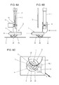
- FIGS. 6A to 6C are diagrams illustrating the cord guide device of the first exemplary embodiment in a case in which the direction in which the cloth is moved is further changed from the state illustrated in FIGS. 5A to 5C , and FIG. 6A is a front view, FIG. 6B is a side view, and FIG. 6C is a bottom view.
- FIGS. 7A and 7B are diagrams illustrating a second exemplary embodiment of the cord guide device of the present disclosure, in which FIG. 7A is an exploded perspective view and FIG. 7B is a perspective view illustrating a state in which the cord guide device has been assembled and an operation lever is inserted in the cord guide device.
- FIGS. 8A to 8C are diagrams illustrating the cord guide device of the second exemplary embodiment, in which FIG. 8A is a front view, FIG. 8B is a side view, and FIG. 8C is a bottom view.
- FIGS. 9A and 9B are diagrams illustrating a third exemplary embodiment of the cord guide device of the present disclosure, in which FIG. 9A is an exploded perspective view and FIG. 9B is a perspective view illustrating a cord guide device that has been assembled.
- FIGS. 10A and 10B are diagrams for describing an angle sensor of the cord guide device of the third exemplary embodiment, in which FIG. 10A is a schematic diagram of the angle sensor and FIG. 10B is a diagram for describing a method of detecting a direction in which the cloth has moved.
- a guide attachment rod 1 illustrated in FIG. 1 is fixed to a sewing machine body (not shown) and is provided immediately behind a sewing needle 2 so as to hang therefrom when viewed from a sewer positioned on a front side of the sewing machine.
- a cord guide device G is attached to a lower end of the guide attachment rod 1 through a holder arm 10 with a bolt 11 .
- the cord guide device G includes a disc-shaped cord guide 5 that includes a needle hole 6 through which the sewing needle 2 is passed and a guide hole 7 through which a piece of cord C is passed, a guide support board 4 that supports an underside of the cord guide 5 , and a pressing holder 3 that restricts an upper surface of the cord guide 5 and that is mounted on the guide attachment rod 1 with the holder arm 10 .
- a roller 25 described later is attached to a lower portion of the cord guide 5 so as to be in contact with a piece of cloth N.
- Reference numeral N in FIG. 1 is a piece of cloth onto which a piece of cord or the like is sewed and is capable of being moved on a bed (not shown) of the sewing machine in the XY direction by being held by an embroidery frame and the like.
- Reference numeral C 1 is a piece of cord that has been sewed onto the cloth N and reference numeral C 2 illustrated by a broken line illustrates a track onto which the cord C is planned to be sewed.
- the pressing holder 3 includes the holder arm 10 and a ring-shaped pressing upper plate 15 that is integrally formed with the holder arm 10 or that is integrally fixed to the holder arm 10 .
- a recess 13 into which the guide attachment rod 1 is fitted forms three surfaces 13 a , 13 b , and 13 c that extend in an axis direction from an upper portion of the holder arm 10 and that are orthogonal to each other.
- the two surfaces 13 a and 13 b and the two surfaces 13 b and 13 c that are orthogonal to each other determine the position of the pressing holder 3 with respect to the guide attachment rod 1 in plan view.
- a horizontal bolt hole 14 that extend perpendicularly with respect to the axis direction and into which the bolt 11 is fitted is provided in the lateral surface of the holder arm 10 so as to cut away the recess 13 .
- Each of the surfaces of the recess 13 and the horizontal bolt hole 14 configures a positioning mechanism that positions the cord guide device G with respect to the sewing machine through the pressing holder 3 .
- Connection portions 16 are provided so as to hang from two opposing portions in the outer peripheral edge of the pressing upper plate 15 , and hook portions 17 that protrude towards the inner side are provided on the lower ends of the connection portions 16 .
- a projection 22 that concentrically protrudes on an upper surface 21 of a disc-shaped base 20 and that slidably fits into a centering hole 18 that forms an inner peripheral edge of the pressing upper plate 15 is provided in the cord guide 5 .
- the guide hole 7 is drilled eccentrically and apart at a predetermined distance d with respect to a center of the needle hole 6 that is drilled at the center of the cord guide 5 .
- the guide hole 7 functions so as to pass the cord C therethrough from above and to guide the cord C to a needle location point therebelow.
- guide arms 24 having the needle hole 6 therebetween extend obliquely downwards from an underside of a base 20 of the cord guide 5 , and shaft holes 27 are provided so as to be set apart at a predetermined distance L from the center of the needle hole 6 and in a direction orthogonal to an X-X line connecting the centers of the needle hole 6 and the guide hole 7 in plan view.
- a rotating shaft 26 to which the roller 25 is attached is disposed in a Y-Y line direction that is orthogonal to the X-X line and is rotatably fitted to the shaft holes 27 .
- the roller 25 comes into contact with the cloth N on the Y-Y line that coincides with the rotating shaft 26 in plan view and that is set apart at the predetermined distance L from the center of the needle hole 6 .
- roller 25 that fits onto the rotating shaft 26 has a shape of a rotating body that has the rotating shaft 26 at the axis of symmetry, and the roller 25 is not limited to the cylindrical roller and maybe a roller having a spherical shape or a roller with an elliptic cross section.
- the guide support board 4 includes a ring-shaped bottom plate 30 and a peripheral wall 31 that stands from a periphery of the bottom plate 30 so as to have a predetermined height. Cutaways 32 into which the connection portions 16 fit are provided in two portions of the peripheral wall 31 at symmetrical positions that oppose each other with respect to an axial center of the peripheral wall 31 .
- An upper surface of the bottom plate 30 supports the underside of the base 20 of the cord guide 5 , and the guide arms 24 protrude from the underside of the base 20 inside an inner periphery of the bottom plate 30 such that free rotation of the cord guide 5 is assured.
- a height of the peripheral wall 31 is configured so as to be slightly higher than a height of the upper surface 21 of the base 20 such that when an underside of the bottom plate 30 is engaged with the hook portions 17 of the connection portions 16 , an upper end of the peripheral wall 31 abuts against the pressing upper plate 15 ; accordingly, the upper surface 21 and an underside of the pressing upper plate 15 do not frictionally slide with respect each other and the cord guide 5 rotates smoothly.
- the roller 25 is attached to the lower portion of the cord guide 5 through the guide arms 24 with the rotating shaft 26 .
- the base 20 of the cord guide 5 is fitted inside the peripheral wall 31 of the guide support board 4 such that the upper surface of the bottom plate 30 supports a peripheral edge portion of the underside of the base 20 .
- connection portions 16 While supporting the cord guide 5 , when the connection portions 16 are placed on the cutaway 32 of the guide support board 4 and the pressing holder 3 is pressed from above, the hook portions 17 are moved over an outer peripheral edge of the bottom plate 30 and are engaged with the underside of the bottom plate 30 such that the pressing holder 3 and the guide support board 4 are connected to each other.
- the centering hole 18 of the pressing upper plate 15 is slidably fitted onto the projection 22 of the cord guide 5 and the underside of the pressing upper plate 15 abuts against the upper end of the peripheral wall 31 such that the cord guide 5 is centered by the centering hole 18 of the pressing upper plate 15 and, as illustrated in FIG. 3B , the cord guide 5 is made capable of rotating smoothly about the needle hole 6 in an M-direction.
- the assembled cord guide device G is moved horizontally until the guide attachment rod 1 abuts against the surface 13 a of the recess 13 or until the bolt 11 abuts against an end portion of the horizontal bolt hole 14 .
- the bolt 11 is fastened furthermore while the holder arm 10 is positioned so that the guide attachment rod 1 abuts against the surface 13 c such that the cord guide device G is positioned and fixed to the sewing machine body with the surfaces 13 b and 13 c that abut against the guide attachment rod 1 and with the bolt 11 and the horizontal bolt hole 14 (see FIG. 3A ).
- the holder arm 10 and the centering hole 18 are provided in the pressing holder 3 so as to position the cord guide 5 with respect to the sewing machine body; however, the cord guide device G of the present disclosure is not necessarily limited to the above positioning and fixing mechanism and the mechanism for positioning and fixing the cord guide 5 to the guide attachment rod 1 and a mechanism for centering the cord guide 5 may be provided on the guide support board 4 side.
- an inner peripheral surface of the peripheral wall 31 may be configured to be in contact with an outer peripheral surface of the base 20 in a slidable manner so as to be used as a centering mechanism.
- a property of the roller trying to forward roll in the direction of movement (the so-called “caster effect” in which the arm of the roller moves so that the roller rotates to meet the direction of movement) is used.
- the guide hole 7 can be positioned so as to always be oriented in the direction opposite to the T-direction with respect to the needle hole 6 , in other words, in the sewing direction, and can be disposed on the planned track C 2 ; accordingly, the sewing needle 2 can reliably catch the cord C and sew the cord C on the cloth N such that a track, that is, cord C 1 , is formed.
- the cord guide 5 following the movement of the cloth N rotates so that the X-X line that connects the guide hole 7 and the needle hole 6 coincides with the T-direction.
- the guide hole 7 is always positioned on the planned track C 2 and in a direction opposite to the T-direction and, accordingly, the sewing needle 2 can keep on sewing while catching the cord C.
- a gap between the underside of the cord guide 5 and the cloth N is, desirably, small to the extent possible.
- the cord guide 5 can be rotated and the cord C can be guided to the needle location point without using a particular driving unit or a controller by just moving the cloth N in the T-direction that is a direction opposite to the sewing direction.
- the cord guide 5 and the guide support board 4 have disc shapes with the needle hole 6 at the center and the gap between the underside and the cloth N is small, and since the roller 25 is in contact with the cloth N, the roller 25 , the cord guide 5 , and the underside of the guide support board 4 serve as a cloth presser that restrict the cloth N from rising; accordingly, a separate cloth presser mechanism is not required.
- the cord guide device G can be fixed to the sewing machine body by just attaching the holder arm 10 of the pressing holder 3 to the guide attachment rod 1 , the present exemplary embodiment can be easily used in a household sewing machine that is not a special purpose embroidery machine.
- the cord guide 5 is equipped with an operation reception portion 43 that includes an insertion hole 44 into which an insertion piece 41 of an operation lever 40 can be fitted.
- the operation reception portion 43 is provided on the underside of the base 20 so as to protrude therefrom and is provided on the outside of the guide arms 24 and inside an inner peripheral edge of the bottom plate 30 of the guide support board 4 .
- the insertion piece 41 is a flat tabular member and the insertion hole 44 has a rectangular-shaped mouth corresponding to the insertion piece 41 ; however, as long as the insertion piece 41 and the insertion hole 44 can be provided in a small gap between the underside of the guide support board 4 and the cloth N, the shapes of the insertion piece 41 and the insertion hole 44 are not limited to the above shapes.
- the pressing holder 3 includes the holder arm 10 and a frame body 45 that is integrally provided with the holder arm 10 .
- the frame body 45 includes a ring-shaped upper plate 46 in which the centering hole 18 is provided and an outer peripheral wall 47 that is provided so as to hang from an outer peripheral edge of the upper plate 46 .
- the outer peripheral wall 47 includes a hook-shaped hole 48 that includes an opening in a lower end thereof and that is bent in a crank-shape so as to extend in a circumferential direction, and a connection recess 49 that has cut away a predetermined circumferential region of the lower end of the outer peripheral wall 47 on the opposite side of the hook-shaped hole 48 in the circumferential direction.
- a fitting projection 50 that is capable of being fitted into the hook-shaped hole 48 is provided in an upper portion of the outer periphery of the peripheral wall 31 of the guide support board 4 and a connection protrusion 51 is provided on a lower portion of the outer periphery on the opposite side of the fitting projection 50 in the circumferential direction.
- a retaining hole 52 through which a retaining screw 53 penetrates is provided in the connection protrusion 51 .
- connection protrusion 51 has a shape that is capable of being slid in the connection recess 49 in the circumferential direction within the range allowing the fitting projection 50 to be rotated until the fitting projection 50 fits into the portion of the hook-shaped hole 48 that is bent and that extends in the circumferential direction when the fitting projection 50 is fitted into the hook-shaped hole 48 through the lower end opening of the hook-shaped hole 48 and when the guide support board 4 is rotated.
- the fitting projection 50 is a tabular member that has a width that is about half of the width of the hook-shaped hole 48 in the circumferential direction
- the connection protrusion 51 is a member that has a width that is about half of the width of the connection recess 49 in the circumferential direction.
- the base 20 of the cord guide 5 is fitted inside the peripheral wall 31 of the guide support board 4 such that the upper surface of the bottom plate 30 supports the underside of the peripheral edge portion of the base 20 .
- the centering hole 18 of the upper plate 46 is slidably fitted onto the projection 22 of the cord guide 5 and the cord guide 5 is centered by the centering hole 18 such that the cord guide 5 rotates smoothly about the needle hole 6 .
- the retaining screw 53 is inserted through the retaining hole 52 and is screwed into the screw hole (not shown) of the pressing holder 3 such that relative movement between the pressing holder 3 and the guide support board 4 is stopped connecting the pressing holder 3 and the guide support board 4 to each other (see FIG. 7B ).
- the hook-shaped hole 48 , the connection recess 49 , the fitting projection 50 , the connection protrusion 51 , and the retaining screw 53 configure a connection mechanism of the pressing holder 3 and the guide support board 4 .
- the assembled cord guide device G positioned with the recess 13 of the holder arm 10 and the horizontal bolt hole 14 is attached to the guide attachment rod 1 .
- the cord guide device G of the present exemplary embodiment is capable of easily rotating the cord guide 5 with the operation of the operation lever 40 .
- the guide hole 7 can be positioned on the planned track C 2 of the cord, and the cord guide 5 can be positioned easily at the start of sewing.
- the effect of the cord guide device G in that the cord guide 5 following the movement of the cloth N rotates so that the guide hole 7 is positioned on the planned track C 2 is similar to that described in the first exemplary embodiment.
- a third exemplary embodiment provided with, as a rotation mechanism, a drive mechanism that rotates the cord guide according to a moving direction of the cloth detected by an angle sensor will be described next.
- a driven gear 61 is provided on the outer peripheral edge of the base 20 of the cord guide 5 .
- a drive mechanism 60 including a drive gear 62 that meshes with the driven gear 61 is accommodated inside a base 66 provided in the base portion of the holder arm 10 of the pressing holder 3 .
- a pulse motor 63 that rotates a shaft 64 on the basis of information from an angle sensor (not shown) is attached to the shaft 64 of the drive gear 62 .
- the pulse motor 63 is mounted in the base 66 so as not to rotate.
- the driven gear 61 that is provided on the outer periphery of the base 20 configures a transmission gear integrally with the base 20 ; however, a transmission gear that transmits rotation to the cord guide 5 may be provided separately from the base 20 .
- a pressing upper plate 67 is provided on an underside of the base 66 of the pressing holder 3 so as to extend horizontally flush with the underside.
- the centering hole 18 is provided in the pressing upper plate 67 .
- the guide support board 4 is provided with the bottom plate 30 on the inner peripheral side of the peripheral wall 31 so as to accommodate and support the cord guide 5 and the drive gear 62 .
- a pressing hole 75 into which a pressing protrusion 65 that is concentrically provided on the lower portion of the base 20 in a protruding manner is fitted is provided in an area of the bottom plate 30 that supports the cord guide 5 .
- the pressing protrusion 65 is configured so as to have the same diameter as the diameter of the projection 22 in which the guide hole 7 is disposed.
- the outer peripheral edge of the underside of the base 20 that is on the outer peripheral side with respect to the pressing protrusion 65 is supported by the bottom plate 30 .
- Lug portions 70 for connecting the guide support board 4 to the pressing holder 3 are provided on the outer peripheral of the peripheral wall 31 in a protruding manner. Retaining holes 71 into which retaining screws 72 are inserted are provided in the lug portions 70 .
- the height of the peripheral wall 31 is configured so that the upper end of the peripheral wall 31 abuts against the undersides of the base 66 and the pressing upper plate 67 when the guide support board 4 is connected to the pressing holder 3 .
- connection mechanism of the pressing holder 3 and the guide support board 4 may be in various forms and is not limited to connection through the screws described above.
- the positioning of the cord guide 5 with respect to the sewing machine body is not limited to positioning through the holder arm 10 of the pressing holder 3 and the centering hole 18 .
- the angle sensor (not shown) will be described. As illustrated in a schematic diagram in FIG. 10A , the angle sensor includes a ball 80 that rotates while being pressed against the cloth N, two detection rollers 83 a and 83 b that abut against the ball 80 , detection shafts 82 a and 82 b that support the two detection rollers 83 a and 83 b , respectively, and that are orthogonal with respect to each other, and encoders 84 a and 84 b that are attached to the detection shafts 82 a and 82 b , respectively.
- the encoders 84 a and 84 b detect the amount of rotation per unit time of the detection rollers 83 a and 83 b , respectively, in other words, the encoders 84 a and 84 b detect rotating speeds Ma and Mb of the detection rollers 83 a and 83 b , respectively, and output the rotation detection signal to an angle calculation unit.
- the angle calculation unit is capable of calculating an angle ⁇ of a moving direction T with respect to the U-U axis in a U-U and V-V coordinate system.
- the calculated angle ⁇ is the actual moving direction of the cloth N, and if the directions of the axes U-U and V-V are inclined against the axes of coordinates of the cloth N, the angle ⁇ may be converted into the axes of coordinates of the cloth N to calculate the actual moving direction of the cloth N.
- Reference numeral 90 in FIG. 9B is a signal wire that connects the pulse motor 63 and the angle sensor (not shown) to the controller in the sewing machine body, and reference numeral 91 is a connector.
- cord guide device G of the present exemplary embodiment not limited to the angle sensor illustrated herein, various known angle sensors that calculate the moving direction with positional information may be employed.
- the pulse motor 63 is accommodated inside the base 66 and the drive mechanism 60 is mounted in the pressing holder 3 .
- the pressing protrusion 65 is fixed into the pressing hole 75 and the guide support board 4 supporting the cord guide 5 is attached to the pressing holder 3 with the retaining screws 72 .
- the projection 22 is fitted into the centering hole 18 and the driven gear 61 and the drive gear 62 are meshed to each other.
- the cord C can be guided to the needle location point in a stable manner and rising of the cloth N caused by the sewing needle 2 can be suppressed small.
- the pulse motor 63 is configured with a simple structure in which the attachment of the pulse motor 63 is completed by merely fitting the pulse motor 63 to the base 66 , the cord guide 5 and the drive mechanism 60 whose gears are meshed to each other can be attached to the pressing holder 3 while being supported by the guide support board 4 .
- the assembled cord guide device G positioned with the recess 13 of the holder arm 10 and the horizontal bolt hole 14 is attached to the guide attachment rod 1 .
- the cord guide device G of the present exemplary embodiment when the cloth N is moved, the ball 80 in contact with the cloth N rotates due to frictional force, the rotating speeds Ma and Mb about the two shafts that are orthogonal with respect to each other are detected by the two detection rollers 83 a and 83 b in contact with the ball 80 , and the angle ⁇ of the moving direction T of the cloth N is calculated with the rotating speeds Ma and Mb.
- the pulse motor 63 rotates the cord guide 5 so that, with respect to the needle hole 6 , the guide hole 7 is always positioned in a direction opposite to the moving direction T of the cloth N.
- the cord guide device of the present disclosure is capable of guiding a piece of cord or the like to a sewing position so that the cord or the like is not deviated from the needle location point by just moving the cloth. Furthermore, since mounting and dismounting of the cord guide device is facilitated with a simple structure, the cord guide device can be suitably used, particularly, in household sewing machines.
Landscapes
- Engineering & Computer Science (AREA)
- Textile Engineering (AREA)
- Sewing Machines And Sewing (AREA)
Abstract
Description
Claims (20)
Applications Claiming Priority (2)
| Application Number | Priority Date | Filing Date | Title |
|---|---|---|---|
| JP2015-024394 | 2015-02-10 | ||
| JP2015024394A JP6468531B2 (en) | 2015-02-10 | 2015-02-10 | CODE GUIDE MECHANISM AND SEWING MACHINE HAVING THE CODE GUIDE MECHANISM |
Publications (2)
| Publication Number | Publication Date |
|---|---|
| US20160230323A1 US20160230323A1 (en) | 2016-08-11 |
| US9863074B2 true US9863074B2 (en) | 2018-01-09 |
Family
ID=56566637
Family Applications (1)
| Application Number | Title | Priority Date | Filing Date |
|---|---|---|---|
| US14/827,651 Expired - Fee Related US9863074B2 (en) | 2015-02-10 | 2015-08-17 | Cord guide device and sewing machine provided with same |
Country Status (4)
| Country | Link |
|---|---|
| US (1) | US9863074B2 (en) |
| JP (1) | JP6468531B2 (en) |
| CN (1) | CN105862273B (en) |
| TW (1) | TWI663302B (en) |
Cited By (4)
| Publication number | Priority date | Publication date | Assignee | Title |
|---|---|---|---|---|
| US11519113B2 (en) | 2020-04-08 | 2022-12-06 | Singer Sourcing Limited Llc | Embroidery accessory with interchangeable guide |
| US11525199B2 (en) | 2019-12-17 | 2022-12-13 | Singer Sourcing Limited Llc | Accessory for sewing machine and methods of using the same |
| US20250043478A1 (en) * | 2021-09-30 | 2025-02-06 | Tism Co., Ltd. | Sewing machine and presser foot device |
| US12385176B2 (en) | 2021-09-30 | 2025-08-12 | Tism Co., Ltd. | Control device and setting device for sewing machine, and sewing machine |
Families Citing this family (5)
| Publication number | Priority date | Publication date | Assignee | Title |
|---|---|---|---|---|
| CN107974770B (en) * | 2017-12-05 | 2020-11-03 | 杰克缝纫机股份有限公司 | Curve sewing device based on flat sewing machine |
| US11519112B2 (en) * | 2020-02-24 | 2022-12-06 | Abbas Baghernejad | Computerized numeric control (CNC) automatic sewing machine |
| CN111962214A (en) * | 2020-10-15 | 2020-11-20 | 浙江美机缝纫机有限公司 | External presser foot mechanism of sewing machine |
| US12123118B2 (en) * | 2021-03-17 | 2024-10-22 | Gracewood Management, Inc. | Sewing hopping foot assembly |
| CN117587586B (en) * | 2023-11-03 | 2025-11-14 | 临朐丽珂清洁用品有限公司 | Twisted seat strip sewing machine and seat cushions produced by the device |
Citations (15)
| Publication number | Priority date | Publication date | Assignee | Title |
|---|---|---|---|---|
| US76054A (en) * | 1868-03-31 | Francis b | ||
| US128825A (en) * | 1872-07-09 | Improvement in braid-guides for sewing-machines | ||
| US268565A (en) * | 1882-12-05 | spbague | ||
| US1182279A (en) * | 1913-08-02 | 1916-05-09 | Singer Mfg Co | Sewing-machine braider or corder. |
| US1593288A (en) * | 1926-03-09 | 1926-07-20 | Jr William C Card | Braiding attachment for sewing machines |
| US2095080A (en) * | 1936-03-14 | 1937-10-05 | Singer Mfg Co | Embroidering and cording attachment for sewing machines |
| US2686484A (en) * | 1951-10-03 | 1954-08-17 | Cuthbertson John Theodore | Sewing machine |
| US2737914A (en) * | 1953-08-17 | 1956-03-13 | Singer Mfg Co | Cording and embroidering presser-foot attachments for sewing machines |
| US5317981A (en) * | 1992-06-10 | 1994-06-07 | Aisin Seiki Kabushiki Kaisha | Programmed pressure foot positioning for control means sewing machine |
| US6748889B2 (en) * | 2002-09-26 | 2004-06-15 | John D. Martelli | Sewing machine pressure foot assembly for quilt designs |
| US7080605B1 (en) * | 2005-01-07 | 2006-07-25 | Anderson Martin L | Pivoting feed roller |
| US7134399B1 (en) * | 2003-02-28 | 2006-11-14 | Gulsby Alma J | Seam gauge |
| JP2008183287A (en) | 2007-01-31 | 2008-08-14 | Barudan Co Ltd | Embroidery sewing machine |
| US8850999B1 (en) * | 2011-02-10 | 2014-10-07 | Daniel K. Kalkbrenner | Sewing machine feed device |
| US9631307B2 (en) * | 2015-03-06 | 2017-04-25 | Janome Sewing Machine Co., Ltd. | Presser foot for sewing machine |
Family Cites Families (12)
| Publication number | Priority date | Publication date | Assignee | Title |
|---|---|---|---|---|
| JPH02468Y2 (en) * | 1987-12-24 | 1990-01-08 | ||
| JPH05168781A (en) * | 1991-07-29 | 1993-07-02 | Rabu Moode:Kk | Fabric presser foot device for sewing machine |
| JP3016954B2 (en) * | 1992-04-10 | 2000-03-06 | 東海工業ミシン株式会社 | Decorative sewing machine |
| JP2006136484A (en) * | 2004-11-11 | 2006-06-01 | Kinoshita Seimitsu Kogyo Kk | Pushing device for embroidery string |
| JP5302728B2 (en) * | 2009-03-23 | 2013-10-02 | 東海工業ミシン株式会社 | Embroidery material guide device for embroidery sewing machine |
| CN201501982U (en) * | 2009-09-10 | 2010-06-09 | 安泰(德清)时装有限公司 | Three-dimensional embroidery mechanism |
| JP2012029801A (en) * | 2010-07-29 | 2012-02-16 | Brother Ind Ltd | Sewing machine |
| CN202139407U (en) * | 2011-05-20 | 2012-02-08 | 天津市创研研磨材料科技有限公司 | Auxiliary equipment for cloth wheel sewing |
| JP6049361B2 (en) * | 2012-09-03 | 2016-12-21 | 東海工業ミシン株式会社 | sewing machine |
| JP6143327B2 (en) * | 2013-02-01 | 2017-06-07 | 蛇の目ミシン工業株式会社 | Embroidery cloth presser |
| CN203270227U (en) * | 2013-04-17 | 2013-11-06 | 吴江市菀坪宝得利缝制设备机械厂 | Wave sewing presser foot cloth feeding cam |
| CN204023163U (en) * | 2014-09-01 | 2014-12-17 | 李世民 | Full-automatic template sewing machine tugboat instrument |
-
2015
- 2015-02-10 JP JP2015024394A patent/JP6468531B2/en not_active Expired - Fee Related
- 2015-08-06 TW TW104125524A patent/TWI663302B/en not_active IP Right Cessation
- 2015-08-11 CN CN201510490160.3A patent/CN105862273B/en not_active Expired - Fee Related
- 2015-08-17 US US14/827,651 patent/US9863074B2/en not_active Expired - Fee Related
Patent Citations (16)
| Publication number | Priority date | Publication date | Assignee | Title |
|---|---|---|---|---|
| US76054A (en) * | 1868-03-31 | Francis b | ||
| US128825A (en) * | 1872-07-09 | Improvement in braid-guides for sewing-machines | ||
| US268565A (en) * | 1882-12-05 | spbague | ||
| US1182279A (en) * | 1913-08-02 | 1916-05-09 | Singer Mfg Co | Sewing-machine braider or corder. |
| US1593288A (en) * | 1926-03-09 | 1926-07-20 | Jr William C Card | Braiding attachment for sewing machines |
| US2095080A (en) * | 1936-03-14 | 1937-10-05 | Singer Mfg Co | Embroidering and cording attachment for sewing machines |
| US2686484A (en) * | 1951-10-03 | 1954-08-17 | Cuthbertson John Theodore | Sewing machine |
| US2737914A (en) * | 1953-08-17 | 1956-03-13 | Singer Mfg Co | Cording and embroidering presser-foot attachments for sewing machines |
| US5317981A (en) * | 1992-06-10 | 1994-06-07 | Aisin Seiki Kabushiki Kaisha | Programmed pressure foot positioning for control means sewing machine |
| US6748889B2 (en) * | 2002-09-26 | 2004-06-15 | John D. Martelli | Sewing machine pressure foot assembly for quilt designs |
| US7134399B1 (en) * | 2003-02-28 | 2006-11-14 | Gulsby Alma J | Seam gauge |
| US7080605B1 (en) * | 2005-01-07 | 2006-07-25 | Anderson Martin L | Pivoting feed roller |
| JP2008183287A (en) | 2007-01-31 | 2008-08-14 | Barudan Co Ltd | Embroidery sewing machine |
| US8850999B1 (en) * | 2011-02-10 | 2014-10-07 | Daniel K. Kalkbrenner | Sewing machine feed device |
| US9150991B1 (en) * | 2011-02-10 | 2015-10-06 | Us Sewing Automation, Inc. | Sewing machine feed device |
| US9631307B2 (en) * | 2015-03-06 | 2017-04-25 | Janome Sewing Machine Co., Ltd. | Presser foot for sewing machine |
Cited By (6)
| Publication number | Priority date | Publication date | Assignee | Title |
|---|---|---|---|---|
| US11525199B2 (en) | 2019-12-17 | 2022-12-13 | Singer Sourcing Limited Llc | Accessory for sewing machine and methods of using the same |
| US11828012B2 (en) | 2019-12-17 | 2023-11-28 | Singer Sourcing Limited Llc | Accessory for sewing machine and methods of using the same |
| US11519113B2 (en) | 2020-04-08 | 2022-12-06 | Singer Sourcing Limited Llc | Embroidery accessory with interchangeable guide |
| US20250043478A1 (en) * | 2021-09-30 | 2025-02-06 | Tism Co., Ltd. | Sewing machine and presser foot device |
| US12281422B2 (en) * | 2021-09-30 | 2025-04-22 | Tism Co., Ltd. | Sewing machine and presser foot device |
| US12385176B2 (en) | 2021-09-30 | 2025-08-12 | Tism Co., Ltd. | Control device and setting device for sewing machine, and sewing machine |
Also Published As
| Publication number | Publication date |
|---|---|
| JP2016146888A (en) | 2016-08-18 |
| TWI663302B (en) | 2019-06-21 |
| US20160230323A1 (en) | 2016-08-11 |
| TW201629292A (en) | 2016-08-16 |
| CN105862273B (en) | 2020-11-27 |
| JP6468531B2 (en) | 2019-02-13 |
| CN105862273A (en) | 2016-08-17 |
Similar Documents
| Publication | Publication Date | Title |
|---|---|---|
| US9863074B2 (en) | Cord guide device and sewing machine provided with same | |
| US4836119A (en) | Sperical ball positioning apparatus for seamed limp material article assembly system | |
| US6802273B2 (en) | Thread breakage detection device for sewing machine | |
| CN104818587A (en) | Sewing machine | |
| JPH04215794A (en) | Sewing machine bobbin thread remaining amount detection device | |
| CN101591839A (en) | Transfer device for sequin supply unit | |
| JP6626715B2 (en) | sewing machine | |
| KR20080016480A (en) | Fully rotary drum | |
| US12270136B2 (en) | Pressing device supporting presser foot and sewing machine provided with the pressing device | |
| KR100504027B1 (en) | Bonding apparatus | |
| CN119145132A (en) | Sewing machine, adjusting method and sensor unit | |
| CN110453396A (en) | Pan embroidery machine head and coil embroidery machine | |
| CN110205753B (en) | Sewing machine and thread tension detection device | |
| JP3668712B2 (en) | Measuring and processing equipment | |
| KR20210058512A (en) | Apparatus for detecting pulley rotation of sewing machine | |
| CN213328160U (en) | Needle bar resetting device of sewing machine | |
| JPS6239836Y2 (en) | ||
| CN213652878U (en) | Sewing machine | |
| JP2005261847A (en) | Shuttle and outside shuttle of sewing machine | |
| CN219828363U (en) | Microwave detection device with adjustable detection direction | |
| CN221501432U (en) | Embroidery machine | |
| JPS6115810Y2 (en) | ||
| JPH0612496U (en) | Embroidery frame fixing device for embroidery machines | |
| KR100476420B1 (en) | Gyro mounting structure for navigation | |
| JP2024078287A (en) | Sewing machine external unit |
Legal Events
| Date | Code | Title | Description |
|---|---|---|---|
| AS | Assignment |
Owner name: JANOME SEWING MACHINE CO., LTD., JAPAN Free format text: ASSIGNMENT OF ASSIGNORS INTEREST;ASSIGNOR:NAKAJIMA, MAKOTO;REEL/FRAME:036339/0336 Effective date: 20150724 |
|
| STCF | Information on status: patent grant |
Free format text: PATENTED CASE |
|
| MAFP | Maintenance fee payment |
Free format text: PAYMENT OF MAINTENANCE FEE, 4TH YEAR, LARGE ENTITY (ORIGINAL EVENT CODE: M1551); ENTITY STATUS OF PATENT OWNER: LARGE ENTITY Year of fee payment: 4 |
|
| AS | Assignment |
Owner name: JANOME CORPORATION, JAPAN Free format text: CHANGE OF NAME;ASSIGNOR:JANOME SEWING MACHINE CO., LTD.;REEL/FRAME:060613/0324 Effective date: 20211001 |
|
| FEPP | Fee payment procedure |
Free format text: MAINTENANCE FEE REMINDER MAILED (ORIGINAL EVENT CODE: REM.); ENTITY STATUS OF PATENT OWNER: LARGE ENTITY |
|
| LAPS | Lapse for failure to pay maintenance fees |
Free format text: PATENT EXPIRED FOR FAILURE TO PAY MAINTENANCE FEES (ORIGINAL EVENT CODE: EXP.); ENTITY STATUS OF PATENT OWNER: LARGE ENTITY |
|
| STCH | Information on status: patent discontinuation |
Free format text: PATENT EXPIRED DUE TO NONPAYMENT OF MAINTENANCE FEES UNDER 37 CFR 1.362 |
|
| FP | Lapsed due to failure to pay maintenance fee |
Effective date: 20260109 |