CROSS REFERENCE TO THE RELATED APPLICATION
This application is a U.S. national stage application, which claims the benefit under 35 USC §371 of PCT International Patent Application No. PCT/JP2015/059574 filed Mar. 27, 2015 which claims foreign priority benefit under 35 USC §119 of Japanese patent application No. 2014-071609, filed Mar. 31, 2014, the contents of which are herein incorporated by reference.
TECHNICAL FIELD
The present invention relates to a socket for electrical component housing an electrical component such as a semiconductor device (hereinafter referred to as an “IC package”).
BACKGROUND ART
Conventionally, as a “socket for electrical component”, a socket is known that houses an electrical component such as a semiconductor device (hereinafter referred to as an “IC package”). As this type of socket for electrical component, there is an IC socket in which a socket body and a cover unit are completely separated, as described in, for example, Japanese Patent Laid-Open No. 2006-252946.
In the IC socket of Japanese Patent Laid-Open No. 2006-252946, as shown in FIG. 5 thereof, an IC package is housed in the socket body, and a push-fit cover unit is set to an upper surface thereof.
Further, a claw of a latch provided to this push-fit cover unit is engaged with the socket body. On this occasion, this latch is biased in the closing direction by a coil spring, such that this push-fit cover unit is held by the socket body.
Then, a push-fit member provided to this push-fit cover unit is made to abut against the upper surface of the IC package, and an adjusting knob provided in a middle portion of this push-fit cover unit is rotated in a horizontal direction so as to press this push-fit member, thereby fixing this IC package.
In this manner, it is possible to fix this IC package with an appropriate pressing force.
SUMMARY OF INVENTION
Technical Problem
However, in such a conventional socket, for example, when conducting an operation test etc. of an IC package, it was difficult to efficiently dissipate heat generated in this IC package.
Accordingly, an object of the present invention is to provide a socket for electrical component with excellent heat dissipation effect.
Solution to Problem
In order to achieve the object, the present invention provides a socket for electrical component, including: a socket body in which an electrical component is housed in a housing portion provided in an upper surface side, and a contact pin to be electrically connected to the electrical component is provided; and a cover member removably provided to the socket body and covering the housing portion of the socket body, in which the cover member includes: a frame-like cover body that is placed on an upper side outer edge portion of the socket body and includes an opening in a middle portion in up and down directions; a heatsink that is provided to penetrate through the opening of the cover body and performs heat dissipation for the electrical component; and a pressing part that is supported by the cover body and moves down the heatsink so as to press the heatsink against the electrical component.
In the present invention, desirably, the pressing part includes a pair of pressing mechanisms and a horizontal bar, the pair of pressing mechanisms are provided to a pair of opposing sides of the cover body, respectively, and move down the heatsink so as to press the heatsink against the electrical component, and the horizontal bar connects the pair of pressing mechanisms to each other.
In the present invention, desirably, an elevating part is provided to the cover body such that the elevating part can be moved up and down, and the heatsink is supported by the elevating part such that the heatsink can be moved up and down, and the heat sink is moved down by moving down the elevating part.
In the present invention, desirably, the elevating part is biased upwardly by a first spring provided to the cover body, and the heatsink is biased downwardly by a second spring provided to the elevating part.
Advantageous Effects of Invention
According to the present invention, by pressing the heatsink against the electrical component with the use of the pressing part, the electrical component is fixed to the housing portion of the socket body. Accordingly, it is possible to make the heatsink perform heat dissipation for the electrical component. Thus, it is possible to obtain excellent heat dissipation effect with respect to the electrical component.
In the present invention, the heatsink is arranged in the middle portion, and the pressing part is arranged on both sides thereof. Thus, it is possible to increase the size of the heatsink, and thus to improve the heat dissipation. Additionally, by connecting the pair of pressing mechanisms to each other by the horizontal bar, it is possible to perform pressing and releasing of the pressing of the electrical component with the heatsink by operating the horizontal bar. Thus, even though the heatsink is arranged in the cover body to penetrate therethrough, the operations of pressing and releasing of the pressing are easy.
In the present invention, by supporting the heatsink by the elevating part and moving down the elevating part by the pressing part, it is possible to press the heatsink against the electrical component.
In the present invention, the pressing part is biased upwardly by a first spring provided to the cover body, and the heatsink is biased downwardly by a second spring provided to the pressing part. Accordingly, it is possible to appropriately set the pressing force of the heatsink with respect to the electrical component.
BRIEF DESCRIPTION OF DRAWINGS
FIG. 1 is a perspective view showing the general configuration of a socket for electrical component in accordance with an embodiment 1 of the present invention.
FIG. 2 is an exploded perspective view showing the configuration of a socket body of the socket for electrical component in accordance with the embodiment 1.
FIG. 3 is a cross-sectional view showing the configuration of a contact module of the socket for electrical component in accordance with the embodiment 1.
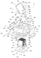
FIG. 4 is an exploded perspective view showing the configuration of a cover member of the socket for electrical component in accordance with the embodiment 1.
FIG. 5 is a cross-sectional view showing the configuration of the cover member of the socket for electrical component in accordance with the embodiment 1.
FIG. 6A is a cross-sectional view showing the configurations of an elevating mechanism and a latch mechanism of the socket for electrical component in accordance with the embodiment 1.
FIG. 6B is a cross-sectional view showing the configurations of the elevating mechanism and the latch mechanism of the socket for electrical component in accordance with the embodiment 1.
FIG. 6C is a cross-sectional view showing the configurations of the elevating mechanism and the latch mechanism of the socket for electrical component in accordance with the embodiment 1.
FIG. 7A is a perspective view for explaining a usage method of the socket for electrical component in accordance with the embodiment 1.
FIG. 7B is a perspective view for explaining the usage method of the socket for electrical component in accordance with the embodiment 1.
FIG. 7C is a perspective view for explaining the usage method of the socket for electrical component in accordance with the embodiment 1.
DESCRIPTION OF EMBODIMENTS
Embodiment 1 of the Present Invention
Hereinbelow, a description is given of an embodiment 1 of the present invention with reference to FIGS. 1 to 7.
As shown in FIG. 1 etc., an IC socket 10 as a “socket for electrical component” includes a socket body 11 and a cover member 12.
The socket body 11 includes, as shown in FIG. 2, a frame-shaped base part 21, a bottom plate 22 covering a bottom surface of this base part 21, an insulating plate 23 provided on an upper surface of this bottom plate 22, and a contact module 24 provided on this insulating plate 23 and housed in the base part 21.
On both left and right side surfaces of the base part 21, a pair of engaging concave portions 21 a are formed to be engaged with engaging claws 45 d, which are provided in bottom end portions of latches 45 described later, for fixing the socket body 11 and the cover member 12. In addition, in the vicinity of both front and back side surfaces of the base part 21, bushings 21 b are provided for positioning the cover member 12 at the time of installation.
Additionally, in the contact module 24, as shown in FIGS. 2 and 3, a first plate 25, a second plate 26, a third plate 27 and a fourth plate (floating plate) 28 are arranged in this order from the bottom, and are fixed apart from each other by using screws 24 a and spacers 24 b.
Then, in each of these plates 25 to 28, respective through-holes 25 a to 28 a for housing contact pins 29 are formed.
In addition, a housing portion 28 b for housing an IC package 13 (see FIG. 7 described later) as an “electrical component” is provided in an upper surface of the topmost fourth plate 28. When the IC package 13 is housed in the housing portion 28 b, each electrode terminal provided on a bottom surface of the IC package 13 is inserted into the through-hole 28 a, and contacts the contact pin 29.
The contact pin 29 includes, as shown in FIG. 3, a conductive stepped cylindrical upper plunger 29 a, a conductive stepped round bar-like lower plunger 29 b, and a coil spring 29 c. Then, the upper plunger 29 a is made to contact with a spherical terminal (not shown) of the IC package 13, and the lower plunger 29 b is made to contact with a wiring substrate (not shown), and further, these upper plunger 29 a and lower plunger 29 b are biased in mutually separating directions by the coil spring 29 c, thereby electrically connecting the IC package 13 to the wiring substrate.
On the other hand, the cover member 12 includes, as shown in FIGS. 1, 4, 5 and 6A to 6C, a frame-like cover body 41 that is placed on the base part 21 of the socket body 11 and includes an opening in a middle portion in the up and down directions. On both left and ride side surfaces of the cover body 41, there are provided latch attaching dents 41 a for fitting thereto top end portions 45 a of the latches 45 (described later), and on both sides of the latch attaching dent 41 a, there are provided shaft holes 41 b for inserting therein a latch shaft 45 b of the latch 45. Further, this cover body 41 is provided with screw holes 41 e for inserting therein screws 41 c for holding an elevating part 43 (described later) via springs 41 d serving as “first springs” of the present invention. Additionally, on end portions of these latch attaching dents 41 a, there are provided vertically elongated holes 41 i (see FIGS. 6A to 6C) for inserting therein latch locking parts 43 b (described later). In addition, on an upper surface side in the vicinity of both front and back side surfaces of the cover body 41, there are provided pressing part insertion holes 41 f for inserting therein a pressing part 46 (described later), and camshaft holes 41 g for rotatably supporting this pressing part 46 with camshafts 46 g. Then, on a lower surface side in the vicinity of both front and back side surfaces of the cover body 41, there are provided guide pins 41 h for positioning for setting the cover member 12 to the socket body 11.
Additionally, the cover member 12 includes, as shown in FIG. 4, a heatsink 42 for fixing and performing heat dissipation for the IC package 13, the elevating part 43 for moving up and down the heatsink 42, and a back plate 44 for attaching the heatsink 42 to the elevating part 43.
On both left and right side surfaces of the heatsink 42, there are provided flange parts 42 c extending toward an outer circumference direction, and each of the left and right flange parts 42 c is provided with two recesses 42 d. Springs 42 f serving as “second springs” of the present invention are fit into the recesses 42 d. Additionally, screws 42 e are screwed into screw holes (not shown) of the elevating part 43 via notches of the flange parts 42 c, so as to fasten and fix the heatsink 42 to the elevating part 43.
The elevating part 43 is, as shown in FIG. 4, formed into a frame-like shape provided with an opening 43 a in a middle portion in the up and down directions, and an upper portion 42 a of the heatsink 42 is fit into this opening 43 a. In addition, on both left and right side surfaces of the elevating part 43, there are provided the latch locking parts 43 b (described later) by using, for example, a screw etc. Further, on a pressed surface 43 c of the elevating part 43, there is provided cam locking parts 43 d protruding therefrom for preventing the rotation of the pressing part 46 (described later) in the opposite direction.
Additionally, as shown in FIG. 4, the back plate 44 is also provided with an opening 44 a in a middle portion in the up and down directions, and a lower portion 42 b of the heatsink 42 is fit into this opening 44 a. Further, the back plate 44 is provided with insertion holes 44 c for inserting therein screws 44 b, and notches 44 e for positioning the back plate 44 by using the guide pins 41 h.
Then, in a state where the lower portion 42 b of the heatsink 42 is fit into the back plate 44, positioning is performed with the guide pins 41 h, and fastening and fixing to a bottom surface of the elevating part 43 is performed by inserting the screws 44 b into the insertion holes 44 c from the down direction.
As shown in FIG. 4, the top end portions 45 a of the latches 45 are fit into the latch attaching dents 41 a of the cover body 41. A shaft hole 45 c for inserting therein the latch shaft 45 b is formed in the top end portion 45 a of the latch 45, such that the shaft hole 45 c penetrates therethrough in the front-back direction. Then, by inserting the latch shaft 45 b into the shaft hole 45 c of the latch 45 and shaft holes 41 b of the cover body 41, the latch 45 is rotatably supported by the cover body 41. Additionally, a latch spring 45 f for biasing the latch 45 in a closing direction is attached to each of the latch attaching dents 41 a.
Here, when the latches 45 are rotated in the closing direction, it is possible to fix the cover member 12 to the socket body 11 by engaging the engaging claws 45 d provided to the bottom end portions of the latches 45 with the engaging concave portions 21 a (see FIG. 2) of the socket body 11. On the other hand, when the latches 45 are rotated in an opening direction, it is possible to remove the cover member 12 from the socket body 11 by releasing the engagement between the engaging claws 45 d and the engaging concave portions 21 a.
In addition, as shown in FIGS. 4 and 6A, on the top end portions 45 a of the latches 45, there are provided locking concave portions 45 e to be engaged with the latch locking parts 43 b of the elevating part 43. As described later, when the elevating part 43 is moved down with the latches 45 closed, the latch locking parts 43 b move down within the elongated holes 41 i of the cover body 41 to be engaged with the locking concave portions 45 e. Consequently, the rotation in the opening direction of the latches 45 is regulated, and locking is made in the closed state.
Additionally, as shown in FIG. 4, the pressing part 46 is attached to the cover body 41. As described later, by rotating this pressing part 46, it is possible to press and move down the elevating part 43 to be pressed against an upper surface of the IC package 13.
The pressing part 46 includes a pair of first cams 46 a and a bail 46 b. The bail 46 b includes a horizontal bar portion 46 c, and a pair of second cams 46 d that are bent at right angle and extend in a rotation radial direction from both ends of the horizontal bar portion 46 c.
The first cams 46 a are, as shown in FIG. 6A, provided with insertion slits 46 j for inserting therein the bail 46 b from the top end side. In addition, these first cams 46 a are provided with shaft holes 46 e and rivet holes 46 r arranged along the rotation radial direction. Additionally, the bottom end portions of these first cams 46 a are provided with, as shown in FIG. 6A, first cam surfaces 46 f to be abut against the pressed surface 43 c of the elevating part 43 in a state where the elevating part 43 is moved up, and second cam surfaces 46 h to be abut against the elevating part 43 in a state where the elevating part 43 is moved down. Further, the first cam surfaces 46 f and the second cam surfaces 46 h of these first cams 46 a are provided with, as shown in FIG. 4, grooves 46 i along a rotation direction. When the first cams 46 a are rotated, the cam locking parts 43 d of the elevating part 43 pass through the inside of the grooves 46 i.
The second cams 46 d of the bail 46 b include short elongated holes 46 k and long elongated holes 46 m arranged along the rotation radial direction. As shown in FIG. 6A, in the tips of the second cams 46 d, lock portions 47 a having a steep angle and gentle-angled portions 47 b having a gentle angle are continuously formed via curved surfaces. In this manner, when the tips of the second cams 46 d abut against the elevating part 43 to move down the elevating part 43, the tips of the second cams 46 d are not locked by the cam locking parts 43 d, and the gentle-angled portions 47 b move on the pressed surface 43 c. However, when an attempt is made to rotate the tips of the second cams 46 d in the opposite direction, the lock portions 47 a are locked by the cam locking parts 43 d, and thus it is possible to prevent the rotation.
When assembling the pressing part 46, first, bail springs 46 n are fit into the long elongated holes 46 m. On this occasion, the bail springs 46 n are fit so as to abut against tip-side end portions of the long elongated holes 46 m. Then, after inserting the second cams 46 d into the insertion slits 46 j of the first cams 46 a, rivets 46 p are inserted into the rivet holes 46 r of the first cams 46 a and the long elongated holes 46 m of the second cams 46 d. In this manner, the first cams 46 a are mounted to the bail 46 b.
Next, the first cams 46 a are inserted into the pressing part insertion holes 41 f of the cover body 41, the camshafts 46 g are put in from the camshaft holes 41 g on both front and back side surfaces of this cover body 41 to be inserted into the shaft holes 46 e of the first cams 46 a and the short elongated holes 46 k of the second cams 46 d. In this manner, the first cams 46 a and the second cams 46 d are rotatably supported by the cover body 41, and it is possible to pull the second cams 46 d in the rotation radial direction against the biasing force of the bail springs 46 n.
Subsequently, a description is given of a usage method of the IC socket 10 in accordance with this embodiment 1.
First, as shown in FIG. 7A etc., the IC package 13 is housed in the housing portion 28 b provided in the contact module 24 of the socket body 11.
Then, the cover member 12 is installed on this socket body 11. On this occasion, by inserting the guide pins 41 h of the cover member into the bushings 21 b of the base part 21, the socket body 11 is positioned with the cover member 12.
Further, as shown in FIG. 7B, the engaging claws 45 d of the latches 45 provided to the cover member 12 are engaged with the engaging concave portions 21 a (see FIG. 7A etc.) provided to the base part 21 of the socket body 11. On this occasion, the first cams 46 a of the pressing part 46 abut against the pressed surface 43 c of the elevating part 43 at the first cam surface 46 f (see FIG. 6A). Additionally, on this occasion, as shown in FIG. 6A, the elevating part 43 is at the highest position due to the biasing force of the springs 41 d. Thus, a bottom surface of the heatsink 42 is not pressed against the upper surface of the IC package 13.
Thereafter, as shown in FIG. 7C, the bail 46 b of the pressing part 46 is rotated from the left side to the right side in FIG. 7C. As described above, the shapes of the tips of the second cams 46 d are formed such that the tips of the second cams 46 d move on the pressed surface 43 c without being locked by the cam locking parts 43 d. Therefore, as shown in FIG. 6B, the second cams 46 d can be rotated in accordance with the rotation of the bail 46 b. In this manner, the first cams 46 a are rotated in accordance with the rotation of the second cams 46 d, and press the pressed surface 43 c of the elevating part 43 in the down direction. Consequently, the elevating part 43 is moved down against the biasing force of the springs 41 d, and the bottom surface of the heatsink 42 is pressed against the upper surface of the IC package 13. In this manner, the IC package 13 is fixed to the housing portion 28 b. As described above, in this embodiment, the elevating part 43 is biased upwardly by the springs 41 d provided in the cover body 41 (see FIG. 4, FIGS. 6A to 6C), and further, the heatsink 42 is biased downwardly by the springs 42 f provided in the elevating part 43 (see FIG. 4, FIG. 5). Thus, it is possible to appropriately set the pressing force of the heatsink 42 with respect to the IC package 13.
Then, when the bail 46 b is rotated to a predetermined position, the second cams 46 d climb over the cam locking parts 43 d, and the second cam surfaces 46 h of the first cams 46 a abut against the pressed surface 43 c of the elevating part 43.
Additionally, on this occasion, since the elevating part 43 is moved down, the latch locking parts 43 b descend within the elongated holes 41 i of the cover body 41 to be engaged with the locking concave portions 45 e of the latches 45. In this manner, the latches 45 are prevented from being rotated in the opening direction, and consequently, the cover member 12 cannot be removed from the socket body 11.
As described above, the shapes of the tips of the second cams 46 d are formed such that the tips of the second cams 46 d are engaged with the cam locking parts 43 d, and the rotation in the opposite direction cannot be made. Thus, once the second cams 46 d climb over the cam locking parts 43 d, the first cams 46 a also cannot be rotated in the opposite direction. Thus, IC socket 10 is locked in a state where the heatsink 42 is pressed against the IC package 13, and the engaging claws 45 d of the latches 45 are engaged with the engaging concave portions 21 a of the socket body 11.
On the other hand, when unlocking this lock, first, as shown in FIG. 6C, the horizontal bar portion 46 c of the bail 46 b is pulled up in a direction away from the elevating part 43. In this manner, because the tips of the second cams 46 d are moved to be above the cam locking parts 43 d, it is possible to rotate the second cams 46 d in the opposite direction, that is, the left direction in FIG. 6C. Then, when the bail 46 b is rotated in the opposite direction, and the tips of the second cams 46 d climb over the cam locking parts 43 d, the elevating part 43 is moved up to the highest position due to the biasing force of the springs 41 d. In this manner, the heatsink 42 is moved up and separated from the IC package 13, and the engagement between the locking concave portions 45 e of the latches 45 and the latch locking parts 43 b of the elevating part 43 is released. Consequently, it is possible to remove the cover member 12 from the socket body 11 by releasing the engagement between the engaging claws 45 d and the engaging concave portions 21 a of the socket body 11.
As explained above, according to this embodiment 1, the IC package 13 is pressed by the heatsink 42 with the use of the pressing part 46, thereby fixing the IC package 13 to the housing portion 28 b of the socket body 11. Accordingly, it is possible to make the heatsink 42 dissipate heat from the IC package 13. Thus, it is possible to obtain excellent heat dissipation effect with respect to the IC package 13.
Additionally, according to this embodiment 1, the structure is employed where the first cam 46 a and the second cam 46 d are provided in the vicinity of each of both front and back side surfaces of the cover body 41, and the second cams 46 d are connected to each other by a horizontal bar portion 46 c. Accordingly, it is possible to arrange the heatsink 42 in the middle portion, and to arrange the pressing part 46 on both sides thereof. Thus, it is possible to increase the size of the heatsink 42, and thus to improve the heat dissipation. Additionally, it is possible to perform fixing and releasing of the fixing of the IC package 13 with the heatsink 42 by operating this horizontal bar portion 46 c. Thus, even though the heatsink 42 is arranged in the cover body 41 to penetrate therethrough, the operations of pressing and releasing of the pressing are easy.
Additionally, according to this embodiment 1, the structure is employed where the heatsink 42 is supported by the elevating part 43. Accordingly, by moving down this elevating part 43 by the pressing part 46, it is possible to press the heatsink 42 against the IC package 13.
Additionally, according to this embodiment 1, the pressing part 46 is fixed to the cover body 41 via the springs 41 d, and the heatsink 42 is fixed to the pressing part 46 via the springs 42 f. Accordingly, it is possible to appropriately set the pressing force of the heatsink 42 with respect to the IC package 13.
Note that, in this embodiment 1, the present invention is applied to the IC socket 10 as a socket for electrical component. However, this is not the limitation, and the present invention may be applied to other things.
REFERENCE SIGNS LIST
- 10 IC socket
- 11 socket body
- 12 cover member
- 13 IC package
- 21 base part
- 21 a engaging concave portion
- 22 bottom plate
- 23 insulating plate
- 24 contact module
- 41 cover body
- 42 heatsink
- 43 elevating part
- 43 b latch locking part
- 43 d cam locking part
- 44 back plate
- 45 latch
- 45 e locking concave portion
- 46 pressing part
- 46 a first cam
- 46 b bail
- 46 c horizontal bar portion
- 46 d second cam
- 46 k short elongated hole
- 46 m long elongated hole
- 46 n bail spring