US9857920B2 - Method and apparatus for providing user interface using acoustic signal, and device including user interface - Google Patents
Method and apparatus for providing user interface using acoustic signal, and device including user interface Download PDFInfo
- Publication number
- US9857920B2 US9857920B2 US13/019,566 US201113019566A US9857920B2 US 9857920 B2 US9857920 B2 US 9857920B2 US 201113019566 A US201113019566 A US 201113019566A US 9857920 B2 US9857920 B2 US 9857920B2
- Authority
- US
- United States
- Prior art keywords
- acoustic signal
- surface acoustic
- user
- signal
- medium
- Prior art date
- Legal status (The legal status is an assumption and is not a legal conclusion. Google has not performed a legal analysis and makes no representation as to the accuracy of the status listed.)
- Active, expires
Links
Images


Classifications
-
- G—PHYSICS
- G06—COMPUTING; CALCULATING OR COUNTING
- G06F—ELECTRIC DIGITAL DATA PROCESSING
- G06F3/00—Input arrangements for transferring data to be processed into a form capable of being handled by the computer; Output arrangements for transferring data from processing unit to output unit, e.g. interface arrangements
- G06F3/01—Input arrangements or combined input and output arrangements for interaction between user and computer
- G06F3/03—Arrangements for converting the position or the displacement of a member into a coded form
- G06F3/041—Digitisers, e.g. for touch screens or touch pads, characterised by the transducing means
- G06F3/043—Digitisers, e.g. for touch screens or touch pads, characterised by the transducing means using propagating acoustic waves
- G06F3/0436—Digitisers, e.g. for touch screens or touch pads, characterised by the transducing means using propagating acoustic waves in which generating transducers and detecting transducers are attached to a single acoustic waves transmission substrate
-
- G—PHYSICS
- G06—COMPUTING; CALCULATING OR COUNTING
- G06F—ELECTRIC DIGITAL DATA PROCESSING
- G06F3/00—Input arrangements for transferring data to be processed into a form capable of being handled by the computer; Output arrangements for transferring data from processing unit to output unit, e.g. interface arrangements
- G06F3/01—Input arrangements or combined input and output arrangements for interaction between user and computer
- G06F3/048—Interaction techniques based on graphical user interfaces [GUI]
- G06F3/0487—Interaction techniques based on graphical user interfaces [GUI] using specific features provided by the input device, e.g. functions controlled by the rotation of a mouse with dual sensing arrangements, or of the nature of the input device, e.g. tap gestures based on pressure sensed by a digitiser
- G06F3/0488—Interaction techniques based on graphical user interfaces [GUI] using specific features provided by the input device, e.g. functions controlled by the rotation of a mouse with dual sensing arrangements, or of the nature of the input device, e.g. tap gestures based on pressure sensed by a digitiser using a touch-screen or digitiser, e.g. input of commands through traced gestures
- G06F3/04883—Interaction techniques based on graphical user interfaces [GUI] using specific features provided by the input device, e.g. functions controlled by the rotation of a mouse with dual sensing arrangements, or of the nature of the input device, e.g. tap gestures based on pressure sensed by a digitiser using a touch-screen or digitiser, e.g. input of commands through traced gestures for inputting data by handwriting, e.g. gesture or text
-
- G—PHYSICS
- G10—MUSICAL INSTRUMENTS; ACOUSTICS
- G10L—SPEECH ANALYSIS OR SYNTHESIS; SPEECH RECOGNITION; SPEECH OR VOICE PROCESSING; SPEECH OR AUDIO CODING OR DECODING
- G10L17/00—Speaker identification or verification
- G10L17/26—Recognition of special voice characteristics, e.g. for use in lie detectors; Recognition of animal voices
Landscapes
- Engineering & Computer Science (AREA)
- Physics & Mathematics (AREA)
- Theoretical Computer Science (AREA)
- General Engineering & Computer Science (AREA)
- Human Computer Interaction (AREA)
- Acoustics & Sound (AREA)
- Health & Medical Sciences (AREA)
- General Physics & Mathematics (AREA)
- Audiology, Speech & Language Pathology (AREA)
- Multimedia (AREA)
- Computational Linguistics (AREA)
- Signal Processing (AREA)
- User Interface Of Digital Computer (AREA)
- General Health & Medical Sciences (AREA)
- Position Input By Displaying (AREA)
Abstract
A user interface using an acoustic signal is provided. A device with the user interface includes a sensor to acquire a surface acoustic signal generated outside of the device, and at least one processor. The processor classifies patterns of the surface acoustic signal by analyzing features of the surface acoustic signal, and identifies a user's input signal corresponding to the surface acoustic signal based on the pattern of the surface acoustic signal.
Description
This application claims the benefit under 35 U.S.C. §119(a) of Korean Patent Application No. 10-2010-0009545, filed on Feb. 2, 2010, and of Korean Patent Application No. 10-2010-0083609, filed on Aug. 27, 2010, in the Korean Intellectual Property Office, the entire disclosures of which are incorporated herein by reference for all purposes.
1. Field
The following description relates to providing a user interface using an acoustic signal, for example, a surface acoustic signal.
2. Description of Related Art
Apparatuses for providing a user interface to operate an electronic device to perform functions have been developed mainly in the form of an operation key, a button, a mouse, or a touch screen. Since conventional user interface providing apparatuses typically include an electronic circuit employing a device such as a button and a screen, there is therefore a limited area in which a user may input a command. In other words, there is a limit in that an area in which such an input device of the electronic circuit is not installed cannot be used as an interface, i.e., cannot be used as an input range. Also, when an interface apparatus is built in a curved area, rather than a flat surface, and in a general object such as a piece of furniture or a wall, the user interface needs to be durable against impacts and contaminants. Such qualities are, however, difficult to achieve.
The conventional user interface providing apparatuses operate in the state of being fixed to a predetermined region of the electronic device. To this end, if an interface of the electronic device, that is, the input range, is disposed in a location difficult for a user to reach, such as inside of clothes or a bag, the interface becomes inconvenient to operate. In particular, when the electronic device has a limited amount of space, for example, as in a mobile device, it is difficult to secure sufficient input space.
Accordingly, there is a desire for an interfacing technology capable of overcoming the limit of the input space of the interface and reducing the cost in comparison with conventional interface devices.
In one general aspect, there is provided an apparatus to provide a user interface of a device, including a surface acoustic signal acquisition unit to acquire a surface acoustic signal generated from a medium disposed outside of the device, a pattern recognition unit to recognize a pattern of the surface acoustic signal by analyzing features of the surface acoustic signal, and a user input identification unit to identify a user's input signal based on the pattern of the surface acoustic signal.
The medium may be provided to the user through an object contacting the device.
The surface acoustic signal acquisition unit may include a medium contactor to receive the surface acoustic signal by contacting the object, and an acoustic sensor to convert the surface acoustic signal to a digital signal.
The medium may be provided to the user through an external casing of the device.
The pattern recognition unit may include a feature extractor to extract a time-domain feature and/or a frequency-domain feature, and a pattern analyzer to analyze the pattern of the surface acoustic signal based on the time-domain feature and/or the frequency-domain feature.
The time-domain feature may include an amplitude of the surface acoustic signal, a distribution of a zero-crossing, an amount of energy, a length of the surface acoustic signal, or a shape of the surface acoustic signal.
The pattern recognition unit may determine a type of the medium using a test signal, and may recognize the pattern of the surface acoustic signal based on the type of the medium.
The pattern recognition unit may estimate a tool generating the surface acoustic signal based on frequency-domain features of the surface acoustic signal, and may recognize the pattern of the surface acoustic signal based on the tool.
The user input identification unit may classify minimal meaningful units matching the pattern of the surface acoustic signal and identifies the user's input signal based on the minimal meaningful units.
The user input identification unit may identify the user's input signal by receiving a plurality of patterns sequentially from the pattern recognition unit and by combining minimal meaningful units corresponding to the plurality of patterns.
The pattern may include information corresponding to a direction of the surface acoustic signal, and the user input identification unit may identify the user's input signal based on the information corresponding to the surface acoustic signal direction.
The apparatus may further include a pattern model storage unit to store pattern models of the surface acoustic signal, classified according to a type of the medium and/or an input tool.
The user's input signal may include a character, a figure, a dragging, a touch event, or any combination thereof, which are input through the medium.
In another general aspect, a method of providing a user interface of a device includes acquiring a surface acoustic signal, extracting a time-domain feature and/or a frequency-domain feature of the surface acoustic signal, analyzing a pattern of the surface acoustic signal based on the time-domain feature and/or the frequency-domain feature, and identifying a user's input signal based on the pattern of the surface acoustic signal.
The analyzing of the pattern of the surface acoustic signal may include determining a type of a medium by using a test signal, estimating a type of a tool that generated the surface acoustic signal based on frequency-domain features of the surface acoustic signal, and recognizing a pattern of the surface acoustic signal based on the type of the medium and/or the tool that generated the surface acoustic signal.
The identifying may include receiving a plurality of patterns sequentially, and identifying the user's input signal by combining minimal meaningful units corresponding to the patterns.
In another general aspect, a method of providing a user interface of a device includes performing an external input mode that receives a user's input signal from a medium disposed outside of the device, recognizing a pattern of a surface acoustic signal corresponding to the medium by analyzing features of the surface acoustic signal in response to the surface acoustic signal being received from the medium, and identifying a user's input signal based on the pattern of the surface acoustic signal.
In another general aspect, a method of providing a user interface of a device includes performing an external input mode that receives a user's input signal from a medium disposed outside of the device, determining a direction of a surface acoustic signal in response to the surface acoustic signal being received from the medium, and performing a function of the device corresponding to the direction of the surface acoustic signal.
The direction of the surface acoustic signal may be determined by a shape of a waveform of the surface acoustic signal, a time difference between a first surface acoustic signal received by a first acoustic sensor and a second surface acoustic signal received by a second acoustic sensor, variation of sizes of the first surface acoustic signal and the second surface acoustic signal, or any combination thereof.
In another general aspect, a device provided with a user interface includes a sensor to acquire a surface acoustic signal generated outside of the device, and at least one processor configured to classify a pattern of the surface acoustic signal by analyzing features of the surface acoustic signal and to identify a user's input signal corresponding to the surface acoustic signal based on the pattern of the surface acoustic signal.
In another general aspect, a method of providing a user interface of a device includes acquiring an acoustic signal generated by a user from outside of the device, analyzing the acquired acoustic signal, and identifying the user's input signal based on the analyzed acoustic signal.
The acoustic signal may be generated by contact between a medium and the user's hand.
The acoustic signal may be generated by contact between a medium and a tool being used by the user.
The acoustic signal may be acquired in a state in which the device is in contact with a medium contacted by the user.
The acoustic signal may be a surface acoustic signal.
In another general aspect, there is provided a device provided with a user interface, including a sensor to sense a surface acoustic signal, and a recognition unit to recognize a user input corresponding to the surface acoustic signal.
The surface acoustic signal may originate from a casing enclosing the device.
The surface acoustic signal may originate from a point remote from the device.
The recognition unit may recognize the user input according to a Location Template Matching scheme and/or a Time Difference of Arrival scheme.
In another general aspect, a method of providing a user interface of a device includes sensing a surface acoustic signal, and recognizing a user input corresponding to the surface acoustic signal.
The recognizing the user input may include analyzing the surface acoustic signal to determine a tool used to generate the surface acoustic signal.
The recognizing the user input may include determining a type of medium outside the device, and analyzing the surface acoustic signal according to the type of medium.
At least two sensors may be used to sense the surface acoustic signal, and the recognizing the user input may be performed according to a spatial difference between the at least two sensors.
Other features and aspects will be apparent from the following detailed description, the drawings, and the claims.
Throughout the drawings and the detailed description, unless otherwise described, the same drawing reference numerals will be understood to refer to the same elements, features, and structures. The relative size and depiction of these elements may be exaggerated for clarity, illustration, and convenience.
The following detailed description is provided to assist the reader in gaining a comprehensive understanding of the methods, apparatuses, and/or systems described herein. Accordingly, various changes, modifications, and equivalents of the systems, apparatuses, and/or methods described herein will be suggested to those of ordinary skill in the art. The progression of operations described is an example; however, the sequence of operations is not limited to that set forth herein and may be changed as is known in the art, with the exception of operations necessarily occurring in a certain order. Also, description of well-known functions and constructions may be omitted for increased clarity and conciseness.
In the following description, “devices” may include a portable device, an electronic device, and the like. A user interface providing apparatus may be a component of the device. That is, the user interface providing apparatus may provide a user interface of the device. The term “device” may include all devices operational by a user, for example, a mobile terminal, a tablet PC, a portable media player, a home appliance, and the like.
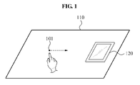
Referring to FIG. 1 , a device 120 may be disposed on an object 110 that includes a specific medium. The object 110 may be, for example, a table, a desk, and the like. A surface acoustic signal, caused by, for example, a user's gesture, may be generated from a surface of the object 110. The user's gesture may include various touch events such as dragging, tapping, etc., for a character input. The surface acoustic signal may be propagated regardless of a shape of the medium, and through all types of the medium, such as air, glass, metal, wood, and the like.
In the example described with reference to FIG. 1 , the surface acoustic signal generated by the user's gesture may correspond to a ‘user's input signal’ used to operate the device 120. The device 120 may perform a function corresponding to the user's input signal. To perform the function corresponding to the user's input signal, the device may be equipped with a function to acquire the user's input signal through an extended interface and a function to identify the user's input signal. In other words, the available interface may be extended away from the physical boundaries of the device itself. The device 120 may precisely understand the user's intention by identifying the user's input signal.
In the example of FIG. 1 , the device 120 may include a sensor to acquire the surface acoustic signal, and at least one processor configured to identify the user's input signal. Additionally, the device 120 may further include a display to indicate the user's input signal or display the operation and/or the function corresponding to the input signal. In this example, the at least one processor may be configured to classify patterns of the surface acoustic signal by analyzing features of the surface acoustic signal, and may identify the user's input signal based on the pattern of the surface acoustic signal. In other words, the surface acoustic signal generated by the user's gesture may be used as an input signal to execute a command to operate the device 120, a character input, and/or other various functions.
The device 120 may acquire an acoustic signal generated by the user from a medium which is independent of the device 120, analyze the acquired acoustic signal, and identify the user's input signal based on the analyzed acoustic signal. The acoustic signal may be generated by contact between the medium and the user's hand. Also, the acoustic signal may be generated by contact between the medium and a tool being used by the user. The tool used by the user may be, for example, a stylus or other such body used to simulate writing, drawing, etc. The acoustic signal may be a surface acoustic signal generated from a surface of the medium.
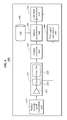
The user interface providing apparatus illustrated in FIG. 2 may be provided in the device 120 of FIG. 1 .
Referring to FIG. 2 , the user interface providing apparatus 200 may include a surface acoustic signal acquisition unit 210, a pattern recognition unit 220, and a user input identification unit 230. The user interface providing apparatus 200 may further include a pattern model storage unit 240.
The surface acoustic signal acquisition unit 210 may acquire a surface acoustic signal generated from a medium disposed outside of the device. The medium may correspond to an extended interface provided to the user through an object contacting the device. Alternatively, or in conjunction with such an extended interface, the medium may be provided to the user through an external casing of the device. The surface acoustic signal acquisition unit 210 may include at least one acoustic sensor. In such a case, the surface acoustic signal may be easily acquired in response to the device 120 being in contact with the medium, and may also be acquirable even when the device 120 is physically separated from the medium. For example, the surface acoustic signal may be acquired even in a case in which the device 120 is physically separated from the medium due to being held by the user.
The pattern recognition unit 220 may analyze features of the surface acoustic signal, and may thereby recognize a pattern of the surface acoustic signal corresponding to the medium. The pattern recognition unit 220 may include a feature extractor 221 to extract time-domain features and/or of frequency-domain features of the surface acoustic signal, and a pattern analyzer 223 to analyze the pattern of the surface acoustic signal based on the time-domain features and/or the frequency-domain features of the surface acoustic signal. The pattern recognition unit 220 may further include a surface acoustic signal processor (not illustrated) to perform operations related to noise removal, signal amplification, signal simplification, and the like. The time-domain features may include an amplitude of the surface acoustic signal, distribution of the zero-crossing, an amount of energy, a length of the surface acoustic signal, a shape of the surface acoustic signal, and the like.
The pattern recognition unit 220 may perform “extraction of the features of the surface acoustic signal,” “estimation of a type of a tool that generated the surface acoustic signal,” and “estimation of a type of a medium propagating the surface acoustic signal.” Accordingly, the pattern recognition unit 220 may precisely recognize the pattern of the surface acoustic signal despite variation of an input tool or a medium.
The user input identification unit 230 may identify the user's input signal based on the surface acoustic signal. The user input identification unit 230 may classify “minimal meaningful units” matching the pattern of the surface acoustic signal and identify the user's input signal based on the “minimal meaningful units.” In addition, the user input identification unit 230 may identify the user's input signal by sequentially receiving a plurality of patterns from the pattern recognition unit 220 and combining the “minimal meaningful units” respectively corresponding to the plurality of patterns. The identified user's input signal may be transmitted to the display and a controller equipped to the device. If the user's input signal is a character, the character input by the user may be displayed. If the user's input signal is a command to execute a specific function, the control unit may execute the function.
The pattern model storage unit 240 may store pattern models of the surface acoustic signals, classified by types of the medium and the input tool. In other words, the pattern model storage unit 240 may store the pattern models of each of the surface acoustic signals that are generated by various mediums and various input tools. For example, pattern models for various letters and/or numbers corresponding to a wooden table top and a plastic stylus may be stored in the pattern model storage unit 240.
Hereinafter, the “extraction of the features of the surface acoustic signal,” the “estimation of a type of a tool that generated the surface acoustic signal,” and the “estimation of a type of the medium propagating the surface acoustic signal” performed by the user interface providing apparatus 200 will be further described. Next, “identification of the user's input signal” performed by the user interface providing apparatus 200 will be further described.
<1. Extraction of Features of Surface Acoustic Signal>
In a process of the extraction of the features of the surface acoustic signal, features beneficial in analysis of the pattern of the surface acoustic signal may be extracted from the surface acoustic signal. According to an example, the extraction may be performed by a hardware device such as a digital signal processor (DSP), a software device, a unit programmed for the hardware device, and so on. For convenience of description, it is presumed herein that the extraction of the features of the surface acoustic signal is performed by the feature extractor 221.
The features of the surface acoustic signal may be classified into the “minimal meaningful units” having specific meanings. The “minimal meaningful unit” is defined as a most basic form beneficial in identification of the user's input signal. As illustrated in FIG. 6 , which will be discussed in more detail later in this description, the “minimal meaningful unit” may include units of the surface acoustic signal, each having a minimal meaning, such as a dot, a circle, a straight line, an alphabet, and the like.
The surface acoustic signal may be acquired as the user artificially generates a sound on a surface of the medium using an object such as a hand and/or a pen. For extraction of the features of the surface acoustic signal, the signal may be analyzed and may be separated into minimal meaningful units. Various minimal meaningful units may each have a unique pattern. Therefore, the feature extractor 221 may be capable of extracting the features from the surface acoustic signal and classifying the minimal meaningful units using the extracted features.
According to an example, the minimal meaningful units may be extracted through five processes described below.
1. A signal S of the minimal meaningful unit may be separated from the acquired surface acoustic signals.
2. The signals S of the minimal meaningful units may be separated into N-number of frames.
3. Feature values CN of each of the N-number of frames may be extracted and stored.
4. Feature values CT of all the acquired surface acoustic signals may be extracted and stored.
5. In response to the pattern model of the minimal meaningful unit being stored in a database (DB), a machine learning model M may be generated using the values CN and CT and the machine learning model M may be stored in the DB.
The above five processes may also be used to store the pattern model of the minimal meaningful unit in the DB. In other words, each pattern model of different mediums and input tools may be stored in the DB The pattern of the surface acoustic signal being currently input may be recognized through comparison between the features extracted from the surface acoustic signal being currently input and the “pattern model of the minimal meaningful unit” stored in the DB.
In the above five processes, the term “feature value” may be a temporally normalized value of the time-domain features of the corresponding signal. Also, the “feature value” may be the frequency-domain features of the corresponding signal. The “pattern model of the minimal meaningful unit” may be generated by properly combining the time-domain features with the frequency-domain features and using various machine learning techniques. The time-domain features may include a standard deviation and a wave slope among amplitudes, dynamic ranges of the amplitudes, distribution of the amplitudes, distribution and variation of the zero-crossing, a sum and variation of energy, a signal length, and the like.
For example, an acoustic signal has a strength level which can be used as a feature value. The number of discrete signal values (amplitude) can be taken from the acoustic signal, and changes between signal values can be measured. The variation of the amplitudes of the signals may be used to identify a straight line, a curve line, a bent line, and the like being input onto the medium.
The feature extractor 221 may classify similar signals using the amplitude distribution of the corresponding signal. For example, distribution of amplitudes of a signal corresponding to a circle may have a uniform distribution.
Distribution of the zero-crossing denotes the number of spots at which a sign of a signal changes. In other words, the zero-crossing denotes a spot at which a signal level reaches zero in one frame. Distribution of the zero-crossing shows a ratio of a high frequency and a low frequency of the signal. For example, presuming that ‘N’ denotes a length of time, the distribution of the zero-crossing may be defined by Equation 1 below.
The feature extractor 221 may extract specific features of the corresponding signal using the zero-crossing distribution, variation of the zero-crossing distribution, and the like.
The feature extractor 221 may use a total sum of energy of the signal as the features of the signal. When ‘N’ denotes a length of time, the total sum of energy of a discrete signal X(i) during the time N may be calculated by Equation 2 as below.
In addition, the feature extractor 221 may use an amount of energy in each of the frames as the features of the signal.
The feature extractor 221 may differentiate the signal through a length of the signal. Time may be a unit for the signal length. For example, a point and a circle have obviously different signal lengths from each other. Therefore, the feature extractor 221 may determine, as the length of the surface acoustic signal, a period of time from a point in time of beginning the acquisition of the surface acoustic signal to a point in time of finishing the acquisition of the surface acoustic signal.
The time-domain features of the signal may be normalized in reference time units and the normalized value may be stored in the DB. In this case, a size of the stored data may be reduced. For example, in a case in which a long straight line and a short straight line exist, features of a straight line may be first recognized, and then relative lengths may be measured using length information.
The frequency-domain features of the signal may be recognized through Fourier transform, spectrum analysis, and the like.
<2. Estimation of Type of Medium Propagating Surface Acoustic Signal>
Estimation of the medium type may be performed by comparing the features extracted from the surface acoustic signal with the pattern model. An input medium used to generate the surface acoustic signal may include a single medium such as glass, a compound medium such as a desk, and the like. The surface acoustic signal may be changed by a shape of surface of the medium. Estimation of the medium type may be performed by any of a hardware device such as a DSP, a software device, and a unit programmed for the hardware device. However, for convenience of description, it is presumed herein that the estimation of the medium type is performed by the pattern recognition unit 220.
The pattern recognition unit 220 may determine the medium type using a test signal and recognize the pattern of the surface acoustic signal based on the medium type. For example, the medium type may be estimated through three processes described below.
1. A test signal may be generated.
2. The surface acoustic signal propagating through the medium in contact with the device may be acquired.
3. Features from the surface acoustic signal acquired in process 2 may be obtained, and the matching medium may be searched for in the DB.
The test signal may be generated by a speaker or a vibration generator provided in or to the device. The test signal may be an acoustic signal of a pre-defined signal having a short period, a vibration, and/or the like. The surface acoustic signal corresponding to the test signal may be acquired by a microphone and a piezoelectric sensor provided in or to the device.
The pattern recognition unit 220 may estimate the type of the medium contacting the device by calculating a distribution range of frequency, the amplitude, and transmission speed of the surface acoustic signal acquired in process 2 and comparing the data with the model stored in the DB. In a case in which there is no model matching the features of the surface acoustic signal acquired in process 2, the pattern recognition unit 220 may determine a most similar model as the medium contacting the device. Such a determination may be made by comparing the acquired distribution range of frequency, amplitude, and transmission speed with corresponding attributes of various models stored in the DB.
If the estimation of the medium type is periodically performed, variation of the medium may be estimated substantially in real time.
<3. Estimation of a Type of a Tool that Generated Surface Acoustic Signal>
Estimation of a type of a tool that generated the surface acoustic signal may be performed by estimating the user's input signal. The input tool may be a finger, a pen, a stylus, or other various tools. That is, the user is capable of operating the device through various input tools such as his or her finger and a stylus. Estimation of a type of a tool may be performed by a hardware device such as a DSP, a software device, a unit programmed for a hardware device, and the like. However, for convenience of description, it is presumed herein that the estimation of a type of a tool is performed by the pattern recognition unit 220.
The pattern recognition unit 220 may perform an estimation of a type of a tool that generated the surface acoustic signal based on the frequency-domain features of the surface acoustic signal, and may recognize the pattern of the surface acoustic signal considering the tool generating the surface acoustic signal.
Frequency features of the signal may be extracted through various methods. For example, the frequency features may be extracted by Discrete Fourier transforming (DFT) the corresponding signal. Also, the frequency features may be extracted using a total power spectrum, a sub-band power, a center frequency, a bandwidth, a spectrum flux, and the like. The frequency features of the input tools may be stored in the DB through a machine learning model.
Various examples of the frequency-domain features of the input tool will be further described with reference to FIG. 7 .
<4. Identification of User's Input Signal>
The identification of the user's input signal determines the user's intention or gesture. The user's input signal may include a simple dragging, character input, tapping, a particular touch event, and the like. The device is able to perform various functions by recognizing the user's input signal.
For example, the device may be set to perform a predetermined function when the user performs dragging from the left to the right on the surface of the medium contacting the device. A dragging direction may be recognized by estimating the direction of the surface acoustic signal. The direction of the surface acoustic signal may be recognized by a single acoustic signal or by a plurality of surface acoustic signals. That is, the pattern of the surface acoustic signal may include information regarding the direction of the surface acoustic signal. The user input identification unit 230 may identify the user's input signal based on the information regarding the direction of the surface acoustic signal.
For example, in a case in which the user inputs a character on the surface of the medium contacting the device, the character may be identified using the “minimal meaningful unit.”
Referring to FIG. 3 , the surface acoustic signal acquisition unit 210 may include a medium contactor 311 and an acoustic sensor 313.
The medium contactor 311 may receive the surface acoustic signal by contacting the object 110. The medium contactor 311 may be made of various materials capable of maintaining close contact with the object 110.
The acoustic sensor 313 may convert the surface acoustic signal to a digital signal. A condenser type microphone, an electronic microphone, a piezoelectric sensor, an ultrasonic sensor, and the like may be used as the acoustic sensor 313. The condenser type microphone and the electronic microphone are noise sensors that may convert a pressure degree of a sound propagating through the medium such as air into an electrical signal. The piezoelectric sensor is a vibration sensor that may convert a pressure obtained from vibration generated by a person or an object to an electrical signal. The ultrasonic sensor may determine a distance or position of an acoustic signal by sensing an ultrasonic wave which is inaudible to human beings.
As illustrated in FIG. 4 , the user interface providing apparatus 400 may include a surface acoustic signal acquisition unit 410, an acoustic signal processing unit 420, a feature extraction unit 430, a DB 440, a pattern determination unit 450, a time signal calculation unit 460, and a user input identification unit 470.
The surface acoustic signal acquisition unit 410 may perform the same or a similar function as the surface acoustic signal acquisition unit 210 of FIG. 2 .
The acoustic signal processing unit 420 may filter noise from the surface acoustic signal and simplify a waveform of the noise-filtered surface acoustic signal. To filter noise and simplify the waveform, the acoustic signal processing unit 420 may include an amplifier 421, a filter 423, and a simplifier 425. The amplifier 421 may amplify the acquired surface acoustic signal. The filter 423 may filter the amplified surface acoustic signal selectively according to specific frequency ranges, thereby removing noise added to the amplified surface acoustic signal. For example, the filter 423 may consider a signal having a greater frequency than a maximum frequency of the surface acoustic signal, that is, 3 KHz, as a noise, and may thereby remove the noise. The simplifier 425 may simplify the noise-filtered surface acoustic signals to process more noise-filtered surface acoustic signals in real time. A signal illustrated in FIG. 5A is a surface acoustic signal output from the filter 423, and a signal illustrated in FIG. 5B is a simplified surface acoustic signal. The ‘amplitude’ of FIGS. 5A and 5B denotes strength or height of the signal and ‘t’ denotes time. The simplifier 435 may determine the height of the signal, thereby simplifying the signal.
The acoustic signal processing unit 420 may output the simplified surface acoustic signal to the feature extraction unit 430, and may output the surface acoustic signal acquired by each sensor of the acoustic signal acquisition unit 410 to the time signal calculation unit 460.
The feature extraction unit 430 may perform the operation previously referred to as “1. Extraction of features of surface acoustic signal.” That is, the feature extraction unit 430 may perform the same or a similar function as the feature extractor 221 of FIG. 2 .
The DB 440 may store pattern models beneficial in recognizing the pattern of the surface acoustic signal and in identifying the user's input signal. For example, the ‘pattern model of the minimal meaningful unit’ and the ‘machine learning model M’ described in “1. Extraction of features of surface acoustic signal” may be stored in the DB 440. The pattern models may be stored according to the input tool. Also, the pattern model may be stored according to the medium type. Therefore, the feature extraction unit 430 may operate, for example, in the order of input tool estimation—input medium estimation—feature extraction, or, as in another example, in the order of input medium estimation—input tool estimation—feature extraction.
An example lookup table of the pattern models stored in the DB 440 is shown in Table 1.
| TABLE 1 | |
| Time-domain features | |
| Standard deviation | Sum total of | Pattern | ||||
| among amplitudes | Zero-crossing | Length | energy | Input tool | Input medium | model |
| 1.2 | 2 | 2 | 3 | Finger | Glass plate | Point |
|
|
||||||
| Nail | Desk | Horizontal | ||||
| line | ||||||
|
|
||||||
| Ball-point | Hardcover | Vertical line | ||||
| pen | of book |
|
||||
| 2 | 1 | 5 | 3 | Finger print | Glass plate |
|
| Nail | Desk |
|
||||
| Ball-point | Hardcover | Circle | ||||
| pen | of book |
|
||||
| . . . | . . . | . . . | . . . | . . . | . . . | . . . |
An example lookup table of the functions of the device, corresponding to the user's input signal, is shown in Table 2.
| TABLE 2 | |||
| Function | |||
| corresponding | |||
| Pattern model | Input tool | Input medium | to device |
| Continuous points | Finger or pen | wood/iron | Power off |
|
|
|||
| Dragging (→ or ←) | Finger or pen | wood/iron | Page up/down |
| Circle |
Finger or pen | wood/iron | Music play |
The pattern determination unit 450 may function in a similar manner to the pattern analyzer 223 of FIG. 2 . In addition, the pattern determination unit 450 may perform the operations previously referred to as “2. Estimation of type of medium propagating surface acoustic signal” and “3. Estimation of tool that generated the surface acoustic signal.”
In an example in which the surface acoustic signal acquisition unit 410 includes at least two sensors, the time signal calculation unit 460 may calculate a time difference of the surface acoustic signals to reach the respective sensors. The time difference calculated by the time signal calculation unit 460 may be used to find the direction of the surface acoustic signal.
The user input identification unit 470 may perform the same or a similar function as the user input identification unit 230 of FIG. 2 .
The signal illustrated in FIG. 5A is the surface acoustic signal output from the filter 423, and the signal illustrated in FIG. 5B is the simplified surface acoustic signal. The ‘amplitude’ of FIGS. 5A-5B denotes strength or height of the signal, and ‘t’ denotes time. The simplifier 435 may determine the height of the signal, thereby simplifying the signal.
The minimal meaningful units illustrated in FIG. 6 may be used to recognize the pattern of the surface acoustic signal and to identify the user's input signal. For example, the pattern recognition unit 220 of FIG. 2 may differentiate between the minimal meaningful units and the surface acoustic signal while the user input identification unit 230 may identify the user's input signal by combining the minimal meaningful units. In an example in which the user inputs  and
and  sequentially on the surface of the medium, the user
 input identification unit 230 may identify the user's input signal as ‘M’.
A signal waveform magnitude, energy, frequency distribution, and the like may be varied according to characteristics of the input tool.
Referring to FIG. 8 , a character ‘A’ may be expressed by inputting two long straight lines 801 and 803 and then one relatively shorter straight line 805. A character ‘H’ may be expressed by inputting a long straight line 807, a short straight line 809, and a long straight line 811, in the above sequence. The pattern showing the order of inputting such minimal meaningful units (straight line) may be used for identification of the character. In response to the user inputting a character ‘F’, the user input identification units 230 and 470 may identify the user's input signal by combining lengths and order of the straight lines 813, 815, and 817.
Referring to FIGS. 9 and 10 , the waveform of the surface acoustic signal may have a symmetrical shape with respect to the advancing direction of the straight line. Therefore, in a case in which the user interface providing apparatus is provided with a single acoustic sensor, the direction of the surface acoustic signal may be identified through a relative shape of the waveform. In a case in which the user interface providing apparatus is provided with at least two acoustic sensors, the direction of the surface acoustic signal may be estimated more precisely, rather than relying on the relative shape of the waveform through a single acoustic sensor.
Referring to FIG. 11 , in a case in which the user makes a sound at the position ‘a’ with a finger, time points for the surface acoustic signal to be received to respective sensors 1110, 1120, 1130, and 1140 are different. In this example, the sensors 1110 to 1140 may be microphones provided to the surface acoustic signal acquisition unit 410. The time signal calculation unit 460 may estimate the position of the surface acoustic signal using the plurality of sensors 1110 to 1140. The time signal calculation unit 460 may determine a provisional position section of the surface acoustic signal by calculating delay times among the sensors 1110 to 1140, and may search for the position only within the provisional position section. The provisional position section may be a position at which the surface acoustic signal is generated.
Alternatively, to minimize the calculation process, the time signal calculation unit 460 may notify the user input signal identification unit 470 that a lower right sensor 1120 has first sensed the surface acoustic signal. In FIG. 11 , since a peak of the surface acoustic signal detected by the lower right sensor 1120 is detected first, the time signal calculation unit 460 may determine that the lower right sensor 1120 first acquired the surface acoustic signal. By virtue of the lower right sensor 1120 detecting the surface acoustic signal first, it may be determined that the lower right sensor 1120 has the closest proximity to the position at which the surface acoustic signal is generated.
The user input signal identification unit 470 may identify the user's input signal by combining the pattern or minimal meaningful units being sequentially recognized. In addition, the user input signal identification unit 470 may determine the direction of the surface acoustic signal with a time difference value calculated by the time signal calculation unit 460.
In a case in which two sensors are provided, thereby forming two channels, the user input signal identification unit 470 may determine whether the surface acoustic signal is generated on the right or the left. For example, when the sensors are disposed on the right and the left, in a case in which the amplitude (magnitude of sound) of the surface acoustic signal acquired by the right sensor gradually decreases whereas the amplitude of the surface acoustic signal acquired by the left sensor gradually increases, the user input signal identification unit 470 may determine that the user performed dragging from the right to the left.
In a case in which four sensors are provided, thereby forming four channels, the user input signal identification unit 470 may determine the direction of the pattern or minimal meaningful unit using the time signal calculated by the time signal calculation unit 460. The user input signal identification unit 470 may determine the direction of the surface acoustic signal and 2D coordinates of the surface acoustic signal, using the time difference value input from the time signal calculation unit 460. For example, the user input signal identification unit 470 may determine the position of the sensor 1110 of FIG. 11 as reference coordinates (0, 0), and differentiate the direction of the surface acoustic signal, and may determine 2D coordinates of the surface acoustic signal generation position.
Alternatively, in the case of having the four channels, the user input signal identification unit 470 may determine the direction of the surface acoustic signal using the position of the sensor first sensing the surface acoustic signal. For example, the user input signal identification unit 470 may determine the direction of the surface acoustic signal by indicating north, south, east and west positions of the sensor 1120 of FIG. 11 .
While FIG. 12 illustrates a user making a sound at a position x,y located on the actual casing of the device itself, such a configuration is simply to aid the ease of description and to present an example. It is understood that the same or similar principles apply in examples in which the sound originating position is located outside of the device provided with such sensors, i.e., in the extended interface previously described.
Referring to FIG. 13 , the user interface providing apparatus may acquire the surface acoustic signal in operation 1310.
The user interface providing apparatus may extract the time-domain features and/or the frequency-domain features of the surface acoustic signal in operation 1320. That is, the user interface providing apparatus may perform the previously described “1. Extraction of features of surface acoustic signal.” The time-domain features may include the amplitude of the surface acoustic signal, the distribution of the zero-crossing, an amount of energy, a length of the surface acoustic signal, a shape of the surface acoustic signal, or any combination thereof.
The user interface providing apparatus may analyze the pattern of the surface acoustic signal based on the time-domain features and/or the frequency-domain features in operation 1330. Operation 1330 may include specific processes illustrated in FIG. 14 . That is, the user interface providing apparatus may determine the type of the medium using the test signal in operation 1431, may estimate a type of a tool that generated the surface acoustic signal based on the frequency-domain features of the surface acoustic signal in operation 1433, and may recognize the pattern of the surface acoustic signal considering the medium type and the tool generating the surface acoustic signal in operation 1435.
The user interface providing apparatus may identify the user's input signal based on the pattern of the surface acoustic signal in operation 1340. In other words, the user interface providing apparatus may perform the previously described “4. Identification of the user's input signal.” According to an example, operation 1340 may include the processes of differentiating the minimal meaningful units matching the surface acoustic signal, and identifying the user's input signal based on the minimal meaningful units. According to to another example, operation 1340 may include the processes of receiving a plurality of the patterns sequentially and combining the minimal meaningful units corresponding to the respective patterns, thereby identifying the user's input signal.
Referring to FIG. 15 , in operation 1510, the user interface providing apparatus may be set to an external input mode to receive the user's input signal through a medium disposed outside of the device. The ‘external input mode’ refers to a mode in which the device 120 is operable through, for example, the outside medium 110 of FIG. 1 . In an example in which the external input mode is performed, the device may activate one or more acoustic sensors which may previously be in an inactive state. The external input mode may be triggered by contact between the device and the outside medium, by a control signal for mode conversion, and the like.
In operation 1520, the user interface providing apparatus may determine whether the surface acoustic signal is received from the outside medium of the device.
In a case in which the surface acoustic signal is received from the outside medium, the user interface providing apparatus may analyze the features of the surface acoustic signal, thereby recognizing the pattern of the surface acoustic signal, in operation 1530.
In operation 1540, the user interface providing apparatus may identify the user's input signal based on the pattern of the surface acoustic signal.
Referring to FIG. 16 , the user interface providing apparatus may be set to the external input mode to receive the user's input signal from the medium disposed outside of the device, in operation 1610. The user interface providing apparatus may also determine the type of the medium by generating the test signal, analyzing features of the test signal on the outside medium, and comparing the features of the test signal with the pattern model stored in advance.
In operation 1620, the user interface providing apparatus may determine whether the surface acoustic signal is received from the outside medium of the device.
Upon reception of the surface acoustic signal from the outside medium, the user interface providing apparatus may determine the direction of the surface acoustic signal in operation 1630. For example, the user interface providing apparatus may determine dragging direction of a user's gesture such as writing, drawing, and the like. The direction of the surface acoustic signal may be determined by the ‘shape of the waveform of the surface acoustic signal’, ‘time difference between a first surface acoustic signal received to a first acoustic sensor and a second surface acoustic signal received to a second acoustic sensor’, and ‘variation of sizes of the first surface acoustic signal and the second surface acoustic signal’, or any combination thereof.
In operation 1640, the user interface providing apparatus may perform a function of the device corresponding to the direction of the surface acoustic signal. For example, according to a setup of the device, in a case in which dragging in a predetermined direction is input after an application program for playing music or a motion picture is executed, the music or motion picture may be played.
As a non-exhaustive illustration only, a terminal or terminal device described herein may refer to mobile devices such as a cellular phone, a personal digital assistant (PDA), a digital camera, a portable game console, an MP3 player, a portable/personal multimedia player (PMP), a handheld e-book, a portable lab-top PC, a global positioning system (GPS) navigation, and devices such as a desktop PC, a high definition television (HDTV), an optical disc player, a setup box, and the like capable of wireless communication or network communication consistent with that disclosed herein. The device, terminal, or terminal device may also be provided as an additional or integrated component on any number of home appliances such as a refrigerator, cooking range, washing machine, television, etc., either fixed or mobile.
The above-described embodiments may be recorded, stored, or fixed in one or more non-transitory computer-readable media that includes program instructions to be implemented by a computer to cause a processor to execute or perform the program instructions. The media may also include, alone or in combination with the program instructions, data files, data structures, and the like. The program instructions recorded on the media may be those specially designed and constructed, or they may be of the kind well-known and available to those having skill in the computer software arts.
A number of examples have been described above. Nevertheless, it will be understood that various modifications may be made. For example, suitable results may be achieved if the described techniques are performed in a different order and/or if components in a described system, architecture, device, or circuit are combined in a different manner and/or replaced or supplemented by other components or their equivalents. Accordingly, other implementations are within the scope of the following claims.
Claims (21)
1. An apparatus to provide a user interface of a device, comprising:
a surface acoustic signal acquisition unit configured to acquire a surface acoustic signal propagated through a medium disposed outside of the device;
a pattern recognition unit configured to (1) estimate a type of a medium using a test signal, (2) estimate a tool generating the surface acoustic signal based on frequency-domain features of the surface acoustic signal and (3) recognize a pattern of the surface acoustic signal based on the type of the medium and the tool by analyzing features of the surface acoustic signal, the pattern recognition unit comprising
a feature extractor configured to extract at least one time-domain feature of the surface acoustic signal, and
a pattern analyzer configured to analyze the pattern of the surface acoustic signal based on the at least one time-domain feature, the type of the medium and the tool; and
a user input identification unit configured to identify a user's input signal by classifying minimal meaningful units corresponding to the pattern of the surface acoustic signal and combining the minimal meaningful units to form one or more input characters.
2. The apparatus of claim 1 , wherein the medium is provided to the user through an object contacting the device.
3. The apparatus of claim 2 , wherein the surface acoustic signal acquisition unit comprises:
a medium contactor to receive the surface acoustic signal by contacting the object; and
an acoustic sensor to convert the surface acoustic signal to a digital signal.
4. The apparatus of claim 1 , wherein the medium is provided to the user through an external casing of the device.
5. The apparatus of claim 1 , wherein:
the feature extractor is configured to extract at least one frequency-domain feature; and
the pattern analyzer is configured to analyze the pattern of the surface acoustic signal based on the at least one frequency-domain feature.
6. The apparatus of claim 1 , wherein the at least one time-domain feature comprises an amplitude of the surface acoustic signal, a distribution of a zero-crossing, an amount of energy, a length of the surface acoustic signal, and/or a shape of the surface acoustic signal.
7. The apparatus of claim 1 , wherein the user input identification unit identifies the user's input signal by receiving a plurality of patterns sequentially from the pattern recognition unit and by combining minimal meaningful units corresponding to the plurality of patterns.
8. The apparatus of claim 1 , wherein the pattern comprises information corresponding to a direction of the surface acoustic signal, and
the user input identification unit identifies the user's input signal based on the information corresponding to the surface acoustic signal direction.
9. The apparatus of claim 1 , further comprising a pattern model storage unit to store pattern models of the surface acoustic signal, classified according to a type of the medium and/or an input tool.
10. The apparatus of claim 1 , wherein the user's input signal comprises a character, a figure, a dragging, a touch event, or any combination thereof, which are input through the medium.
11. The apparatus of claim 1 , wherein the at least one time-domain feature comprises a total sum of energy based on a summation of discrete energy measurements distributed over a length of time.
12. The apparatus of claim 1 , wherein the amplitude of the signals are used to identify a straight line, a curve line, a bent line, being input onto the medium.
13. The apparatus of claim 1 , wherein the feature extractor is configured to extract specific features of the corresponding signal using a zero-crossing distribution and a variation of the zero-crossing distribution such that the distribution of the zero-crossing denotes a number of spots at which a sign of the signal changes.
14. The apparatus of claim 1 , wherein the tool is a stylus.
15. A method of providing a user interface of a device, the method comprising:
acquiring a surface acoustic signal;
extracting at least one time-domain feature of the surface acoustic signal;
determining a type of a medium using a test signal;
estimating a tool generating the surface acoustic signal based on frequency-domain features of the surface acoustic signal;
analyzing a pattern of the surface acoustic signal based on the at least one time-domain feature, the type of the medium and the tool; and
identifying a user's input signal by classifying minimal meaningful units corresponding to the pattern of the surface acoustic signal and combining the minimal meaningful units to form one or more input characters.
16. The method of claim 15 , wherein the identifying comprises:
receiving a plurality of patterns sequentially; and
identifying the user's input signal by combining minimal meaningful units corresponding to the patterns.
17. The method of claim 15 , wherein the surface acoustic signal is generated by contact between the medium and the user's hand.
18. The method of claim 15 , wherein the surface acoustic signal is generated by contact between the medium and a tool being used by the user.
19. The method of claim 15 , wherein the surface acoustic signal is acquired in a state in which the device is in contact with the medium.
20. The method of claim 15 , comprising:
extracting at least one frequency domain feature of the surface acoustic signal; and
analyzing the pattern of the surface acoustic signal based on the at least one frequency domain feature.
21. A method of providing a user interface of a device, the method comprising:
acquiring an acoustic signal generated by a user interacting with a medium of an object outside of the device;
analyzing the acquired acoustic signal through a process that comprises separating the surface acoustic signal into a plurality of frames based on at least one time-domain feature of the acquired acoustic signal; and
identifying the user's input signal by classifying minimal meaningful units corresponding to a pattern of the acoustic signal and combining the minimal meaningful units to form one or more input characters.
Applications Claiming Priority (4)
| Application Number | Priority Date | Filing Date | Title |
|---|---|---|---|
| KR10-2010-0009545 | 2010-02-02 | ||
| KR20100009545 | 2010-02-02 | ||
| KR1020100083609A KR101678549B1 (en) | 2010-02-02 | 2010-08-27 | Method and apparatus for providing user interface using surface acoustic signal, and device with the user interface |
| KR10-2010-0083609 | 2010-08-27 |
Publications (2)
| Publication Number | Publication Date |
|---|---|
| US20110191680A1 US20110191680A1 (en) | 2011-08-04 |
| US9857920B2 true US9857920B2 (en) | 2018-01-02 |
Family
ID=44342706
Family Applications (1)
| Application Number | Title | Priority Date | Filing Date |
|---|---|---|---|
| US13/019,566 Active 2033-10-05 US9857920B2 (en) | 2010-02-02 | 2011-02-02 | Method and apparatus for providing user interface using acoustic signal, and device including user interface |
Country Status (6)
| Country | Link |
|---|---|
| US (1) | US9857920B2 (en) |
| EP (2) | EP2544077B1 (en) |
| JP (1) | JP5789270B2 (en) |
| KR (1) | KR101678549B1 (en) |
| CN (1) | CN102741919B (en) |
| WO (1) | WO2011096694A2 (en) |
Cited By (2)
| Publication number | Priority date | Publication date | Assignee | Title |
|---|---|---|---|---|
| US10803389B2 (en) * | 2012-11-09 | 2020-10-13 | Samsung Electronics Co., Ltd. | Apparatus and method for determining user's mental state |
| US11369995B2 (en) * | 2017-05-29 | 2022-06-28 | Hap2U | Method for controlling a mobile device |
Families Citing this family (55)
| Publication number | Priority date | Publication date | Assignee | Title |
|---|---|---|---|---|
| US11327599B2 (en) | 2011-04-26 | 2022-05-10 | Sentons Inc. | Identifying a contact type |
| US10198097B2 (en) | 2011-04-26 | 2019-02-05 | Sentons Inc. | Detecting touch input force |
| US9477350B2 (en) | 2011-04-26 | 2016-10-25 | Sentons Inc. | Method and apparatus for active ultrasonic touch devices |
| US9639213B2 (en) | 2011-04-26 | 2017-05-02 | Sentons Inc. | Using multiple signals to detect touch input |
| US9189109B2 (en) | 2012-07-18 | 2015-11-17 | Sentons Inc. | Detection of type of object used to provide a touch contact input |
| JP6280867B2 (en) * | 2011-10-18 | 2018-02-14 | カーネギー メロン ユニバーシティ | Method and apparatus for classifying touch events on a touch sensor surface |
| US9449476B2 (en) | 2011-11-18 | 2016-09-20 | Sentons Inc. | Localized haptic feedback |
| US11262253B2 (en) | 2017-08-14 | 2022-03-01 | Sentons Inc. | Touch input detection using a piezoresistive sensor |
| US10235004B1 (en) | 2011-11-18 | 2019-03-19 | Sentons Inc. | Touch input detector with an integrated antenna |
| EP2780783B1 (en) | 2011-11-18 | 2022-12-28 | Sentons Inc. | Detecting touch input force |
| US9886091B2 (en) * | 2012-03-15 | 2018-02-06 | Nokia Technologies Oy | Tactile apparatus link |
| US9348468B2 (en) | 2013-06-07 | 2016-05-24 | Sentons Inc. | Detecting multi-touch inputs |
| US9078066B2 (en) * | 2012-07-18 | 2015-07-07 | Sentons Inc. | Touch input surface speaker |
| US9281727B1 (en) * | 2012-11-01 | 2016-03-08 | Amazon Technologies, Inc. | User device-based control of system functionality |
| KR101371749B1 (en) | 2012-11-09 | 2014-03-07 | 현대자동차(주) | Vehicle control devices |
| US9430098B2 (en) * | 2012-12-17 | 2016-08-30 | Apple Inc. | Frequency sensing and magnification of portable device output |
| US9134856B2 (en) * | 2013-01-08 | 2015-09-15 | Sony Corporation | Apparatus and method for controlling a user interface of a device based on vibratory signals |
| KR20140113119A (en) * | 2013-03-15 | 2014-09-24 | 엘지전자 주식회사 | Electronic device and control method therof |
| KR20140114766A (en) | 2013-03-19 | 2014-09-29 | 퀵소 코 | Method and device for sensing touch inputs |
| US9612689B2 (en) | 2015-02-02 | 2017-04-04 | Qeexo, Co. | Method and apparatus for classifying a touch event on a touchscreen as related to one of multiple function generating interaction layers and activating a function in the selected interaction layer |
| US9013452B2 (en) | 2013-03-25 | 2015-04-21 | Qeexo, Co. | Method and system for activating different interactive functions using different types of finger contacts |
| KR101500130B1 (en) * | 2013-09-02 | 2015-03-06 | 현대자동차주식회사 | Apparatus for Controlling Vehicle installation on Steering wheel |
| US10114486B2 (en) * | 2013-09-19 | 2018-10-30 | Change Healthcare Holdings, Llc | Method and apparatus for providing touch input via a touch sensitive surface utilizing a support object |
| US9459715B1 (en) | 2013-09-20 | 2016-10-04 | Sentons Inc. | Using spectral control in detecting touch input |
| KR101509947B1 (en) * | 2013-10-23 | 2015-04-07 | 현대자동차주식회사 | Apparatus, Method and System for Checking of Rear Lamp |
| US20150242036A1 (en) * | 2014-02-21 | 2015-08-27 | Amin Heidari | System and method for detecting taps on a surface or on a device |
| JP6281745B2 (en) * | 2014-03-06 | 2018-02-21 | カシオ計算機株式会社 | Sliding operation detection device, electronic device and program |
| US9329715B2 (en) | 2014-09-11 | 2016-05-03 | Qeexo, Co. | Method and apparatus for differentiating touch screen users based on touch event analysis |
| US11619983B2 (en) | 2014-09-15 | 2023-04-04 | Qeexo, Co. | Method and apparatus for resolving touch screen ambiguities |
| US9864453B2 (en) | 2014-09-22 | 2018-01-09 | Qeexo, Co. | Method and apparatus for improving accuracy of touch screen event analysis by use of edge classification |
| US10606417B2 (en) | 2014-09-24 | 2020-03-31 | Qeexo, Co. | Method for improving accuracy of touch screen event analysis by use of spatiotemporal touch patterns |
| US10282024B2 (en) | 2014-09-25 | 2019-05-07 | Qeexo, Co. | Classifying contacts or associations with a touch sensitive device |
| KR20160045545A (en) * | 2014-10-17 | 2016-04-27 | 엘지전자 주식회사 | Refrigerator |
| KR102306537B1 (en) * | 2014-12-04 | 2021-09-29 | 삼성전자주식회사 | Method and device for processing sound signal |
| CN105828265A (en) * | 2015-01-10 | 2016-08-03 | 深圳富泰宏精密工业有限公司 | System and method of detecting accessory |
| JP6543054B2 (en) * | 2015-03-17 | 2019-07-10 | 株式会社メガチップス | Information accepting apparatus, program and information input method |
| JP6543055B2 (en) * | 2015-03-17 | 2019-07-10 | 株式会社メガチップス | Information reception system, program and information input method |
| WO2016148120A1 (en) * | 2015-03-17 | 2016-09-22 | 株式会社メガチップス | Information reception system, recording medium, and information input method |
| US10592817B2 (en) * | 2015-07-13 | 2020-03-17 | International Business Machines Corporation | Parameter-dependent model-blending with multi-expert based machine learning and proxy sites |
| US10642404B2 (en) | 2015-08-24 | 2020-05-05 | Qeexo, Co. | Touch sensitive device with multi-sensor stream synchronized data |
| KR101892794B1 (en) | 2015-08-25 | 2018-08-28 | 엘지전자 주식회사 | Refrigerator |
| US10048811B2 (en) | 2015-09-18 | 2018-08-14 | Sentons Inc. | Detecting touch input provided by signal transmitting stylus |
| KR101862564B1 (en) | 2016-01-05 | 2018-05-30 | 엘지전자 주식회사 | Refrigerator |
| WO2017186290A1 (en) * | 2016-04-27 | 2017-11-02 | Mogees Limited | Method to recognize a gesture and corresponding device |
| US10908741B2 (en) | 2016-11-10 | 2021-02-02 | Sentons Inc. | Touch input detection along device sidewall |
| US10296144B2 (en) | 2016-12-12 | 2019-05-21 | Sentons Inc. | Touch input detection with shared receivers |
| US10126877B1 (en) | 2017-02-01 | 2018-11-13 | Sentons Inc. | Update of reference data for touch input detection |
| US20180239435A1 (en) * | 2017-02-22 | 2018-08-23 | International Business Machines Corporation | Smart devices having recognition features |
| US10585522B2 (en) | 2017-02-27 | 2020-03-10 | Sentons Inc. | Detection of non-touch inputs using a signature |
| US11580829B2 (en) | 2017-08-14 | 2023-02-14 | Sentons Inc. | Dynamic feedback for haptics |
| US11009989B2 (en) | 2018-08-21 | 2021-05-18 | Qeexo, Co. | Recognizing and rejecting unintentional touch events associated with a touch sensitive device |
| US10942603B2 (en) | 2019-05-06 | 2021-03-09 | Qeexo, Co. | Managing activity states of an application processor in relation to touch or hover interactions with a touch sensitive device |
| US11231815B2 (en) | 2019-06-28 | 2022-01-25 | Qeexo, Co. | Detecting object proximity using touch sensitive surface sensing and ultrasonic sensing |
| US11592423B2 (en) | 2020-01-29 | 2023-02-28 | Qeexo, Co. | Adaptive ultrasonic sensing techniques and systems to mitigate interference |
| CN113220167B (en) * | 2021-05-19 | 2024-03-12 | 京东方科技集团股份有限公司 | Display module and ultrasonic touch detection method |
Citations (48)
| Publication number | Priority date | Publication date | Assignee | Title |
|---|---|---|---|---|
| US4654648A (en) * | 1984-12-17 | 1987-03-31 | Herrington Richard A | Wireless cursor control system |
| US4718102A (en) * | 1983-01-19 | 1988-01-05 | Communication Intelligence Corporation | Process and apparatus involving pattern recognition |
| US4772764A (en) * | 1983-12-01 | 1988-09-20 | Xecutek Corporation | Soundwave position digitizer |
| EP0421025A1 (en) | 1989-10-02 | 1991-04-10 | Koninklijke Philips Electronics N.V. | Data processing system with a touch screen and a digitizing tablet, both integrated in an output device |
| US5541892A (en) * | 1993-12-03 | 1996-07-30 | Canon Kabushiki Kaisha | Piezoelectric sensor and coordinate input apparatus employing the same |
| US5750941A (en) | 1994-12-15 | 1998-05-12 | Fujitsu Limited | Ultrasonic coordinates input device |
| KR19980019048A (en) | 1996-08-29 | 1998-06-05 | 로더리히 네테부쉬 | IDENTIFICATION OR SENSOR ARRANGEMENT-SAW ARRANGEMENT-OPERATING WITH SURFACE ACOUSTIC WAVES |
| US5854450A (en) * | 1995-04-19 | 1998-12-29 | Elo Touchsystems, Inc. | Acoustic condition sensor employing a plurality of mutually non-orthogonal waves |
| US20010003452A1 (en) | 1999-12-08 | 2001-06-14 | Telefonaktiebolaget L M Ericsson (Publ) | Portable communication device and method |
| US20010006006A1 (en) * | 1999-12-23 | 2001-07-05 | Hill Nicholas P.R. | Contact sensitive device |
| US6313825B1 (en) * | 1998-12-28 | 2001-11-06 | Gateway, Inc. | Virtual input device |
| US20020009227A1 (en) * | 1993-10-06 | 2002-01-24 | Xerox Corporation | Rotationally desensitized unistroke handwriting recognition |
| US20020075240A1 (en) * | 2000-05-29 | 2002-06-20 | Vkb Inc | Virtual data entry device and method for input of alphanumeric and other data |
| US6429846B2 (en) * | 1998-06-23 | 2002-08-06 | Immersion Corporation | Haptic feedback for touchpads and other touch controls |
| US20030016437A1 (en) * | 2000-01-12 | 2003-01-23 | Islam Mohammed N. | Low-noise distributed raman amplifier using bi-directional pumping using multiple raman orders |
| JP3385094B2 (en) | 1994-05-23 | 2003-03-10 | 松下電器産業株式会社 | Portable information terminals |
| US20030066692A1 (en) * | 2000-06-29 | 2003-04-10 | Fabrice Devige | Accurate interactive acoustic plate |
| US20030132921A1 (en) * | 1999-11-04 | 2003-07-17 | Torunoglu Ilhami Hasan | Portable sensory input device |
| US20030217873A1 (en) * | 2002-05-24 | 2003-11-27 | Massachusetts Institute Of Technology | Systems and methods for tracking impacts |
| US6703570B1 (en) * | 2000-05-10 | 2004-03-09 | International Business Machines Corporation | Digital pen using ultrasonic tracking |
| US20040047505A1 (en) * | 2001-12-26 | 2004-03-11 | Firooz Ghassabian | Stylus computer |
| US20040246240A1 (en) * | 2003-06-09 | 2004-12-09 | Microsoft Corporation | Detection of a dwell gesture by examining parameters associated with pen motion |
| JP2005018611A (en) | 2003-06-27 | 2005-01-20 | Yamatake Corp | Command input device and method |
| US20050078093A1 (en) * | 2003-10-10 | 2005-04-14 | Peterson Richard A. | Wake-on-touch for vibration sensing touch input devices |
| JP2005529350A (en) | 2002-06-12 | 2005-09-29 | サントル・ナショナル・ドゥ・ラ・レシェルシュ・サイエンティフィーク−セ・エン・エール・エス− | Method and apparatus for locating impact on a surface |
| US7050177B2 (en) * | 2002-05-22 | 2006-05-23 | Canesta, Inc. | Method and apparatus for approximating depth of an object's placement onto a monitored region with applications to virtual interface devices |
| US20060192763A1 (en) * | 2005-02-25 | 2006-08-31 | Ziemkowski Theodore B | Sound-based virtual keyboard, device and method |
| US20060210163A1 (en) * | 2005-03-17 | 2006-09-21 | Microsoft Corporation | Word or character boundary-based scratch-out gesture recognition |
| US20070006651A1 (en) * | 2005-07-06 | 2007-01-11 | Kruger Silvio E | Method and system for determining material properties using ultrasonic attenuation |
| US20070173240A1 (en) * | 2006-01-25 | 2007-07-26 | Microsoft Corporation | Handwriting style data input via keys |
| JP2007312309A (en) | 2006-05-22 | 2007-11-29 | Fujitsu Ltd | Mobile terminal device and method of operating the same |
| JP2007336513A (en) | 2006-05-15 | 2007-12-27 | Seiko Epson Corp | Patting command processing system, operating system for portable equipment, and portable equipment |
| US20080084789A1 (en) * | 2004-05-17 | 2008-04-10 | Epos Technologies Limited | Acoustic Robust Synchronization Signaling for Acoustic Positioning System |
| WO2008047294A2 (en) | 2006-10-18 | 2008-04-24 | Koninklijke Philips Electronics N.V. | Electronic system control using surface interaction |
| US7411581B2 (en) * | 2002-02-06 | 2008-08-12 | Soundtouch Limited | Touch pad |
| US20080309641A1 (en) | 2007-06-15 | 2008-12-18 | Jacob Harel | Interactivity in a large flat panel display |
| KR20090042854A (en) | 2006-08-24 | 2009-04-30 | 콸콤 인코포레이티드 | Mobile device with acoustically-driven text input and method thereof |
| US20090195517A1 (en) * | 2007-12-21 | 2009-08-06 | Sensitive Object | Method for determining the locations of at least two impacts |
| WO2009115799A1 (en) * | 2008-03-18 | 2009-09-24 | Elliptic Laboratories As | Object and movement detection |
| US20090256815A1 (en) * | 2008-04-14 | 2009-10-15 | Microsoft Corporation | Active matrix touch sensing |
| US20090295758A1 (en) * | 2008-05-27 | 2009-12-03 | Industrial Technology Research Institute | Method for writing motion and trajectory recognition and writing apparatus and recognizing system |
| US20110037734A1 (en) * | 2009-08-17 | 2011-02-17 | Apple Inc. | Electronic device housing as acoustic input device |
| US20110084940A1 (en) * | 2009-10-09 | 2011-04-14 | Samsung Electronics Co., Ltd. | Mobile device and method for processing an acoustic signal |
| US20110175813A1 (en) * | 2010-01-20 | 2011-07-21 | Apple Inc. | Piezo-based acoustic and capacitive detection |
| US20110242059A1 (en) * | 2010-03-31 | 2011-10-06 | Research In Motion Limited | Method for receiving input on an electronic device and outputting characters based on sound stroke patterns |
| US20120056804A1 (en) * | 2006-06-28 | 2012-03-08 | Nokia Corporation | Apparatus, Methods And Computer Program Products Providing Finger-Based And Hand-Based Gesture Commands For Portable Electronic Device Applications |
| US8890821B2 (en) * | 2009-10-09 | 2014-11-18 | Egalax—Empia Technology Inc. | Method and device for dual-differential sensing |
| US20140363083A1 (en) * | 2013-06-09 | 2014-12-11 | Apple Inc. | Managing real-time handwriting recognition |
Family Cites Families (4)
| Publication number | Priority date | Publication date | Assignee | Title |
|---|---|---|---|---|
| JP2535626B2 (en) * | 1989-10-27 | 1996-09-18 | キヤノン株式会社 | Coordinate input device |
| JP2592972B2 (en) * | 1989-12-25 | 1997-03-19 | キヤノン株式会社 | Coordinate input device |
| US8614695B2 (en) * | 2005-06-07 | 2013-12-24 | Intel Corporation | Ultrasonic tracking |
| CN101308434B (en) * | 2007-05-15 | 2011-06-22 | 宏达国际电子股份有限公司 | User interface operation method |
-
2010
- 2010-08-27 KR KR1020100083609A patent/KR101678549B1/en active IP Right Grant
-
2011
- 2011-02-01 EP EP12182555.8A patent/EP2544077B1/en active Active
- 2011-02-01 JP JP2012551100A patent/JP5789270B2/en active Active
- 2011-02-01 WO PCT/KR2011/000680 patent/WO2011096694A2/en active Application Filing
- 2011-02-01 EP EP11739990.7A patent/EP2532000B1/en active Active
- 2011-02-01 CN CN201180008099.4A patent/CN102741919B/en active Active
- 2011-02-02 US US13/019,566 patent/US9857920B2/en active Active
Patent Citations (54)
| Publication number | Priority date | Publication date | Assignee | Title |
|---|---|---|---|---|
| US4718102A (en) * | 1983-01-19 | 1988-01-05 | Communication Intelligence Corporation | Process and apparatus involving pattern recognition |
| US4772764A (en) * | 1983-12-01 | 1988-09-20 | Xecutek Corporation | Soundwave position digitizer |
| US4654648A (en) * | 1984-12-17 | 1987-03-31 | Herrington Richard A | Wireless cursor control system |
| EP0421025A1 (en) | 1989-10-02 | 1991-04-10 | Koninklijke Philips Electronics N.V. | Data processing system with a touch screen and a digitizing tablet, both integrated in an output device |
| US20020009227A1 (en) * | 1993-10-06 | 2002-01-24 | Xerox Corporation | Rotationally desensitized unistroke handwriting recognition |
| US5541892A (en) * | 1993-12-03 | 1996-07-30 | Canon Kabushiki Kaisha | Piezoelectric sensor and coordinate input apparatus employing the same |
| JP3385094B2 (en) | 1994-05-23 | 2003-03-10 | 松下電器産業株式会社 | Portable information terminals |
| US5750941A (en) | 1994-12-15 | 1998-05-12 | Fujitsu Limited | Ultrasonic coordinates input device |
| US5854450A (en) * | 1995-04-19 | 1998-12-29 | Elo Touchsystems, Inc. | Acoustic condition sensor employing a plurality of mutually non-orthogonal waves |
| KR19980019048A (en) | 1996-08-29 | 1998-06-05 | 로더리히 네테부쉬 | IDENTIFICATION OR SENSOR ARRANGEMENT-SAW ARRANGEMENT-OPERATING WITH SURFACE ACOUSTIC WAVES |
| US6429846B2 (en) * | 1998-06-23 | 2002-08-06 | Immersion Corporation | Haptic feedback for touchpads and other touch controls |
| US6313825B1 (en) * | 1998-12-28 | 2001-11-06 | Gateway, Inc. | Virtual input device |
| US20030132921A1 (en) * | 1999-11-04 | 2003-07-17 | Torunoglu Ilhami Hasan | Portable sensory input device |
| CN1409839A (en) | 1999-12-08 | 2003-04-09 | 艾利森电话股份有限公司 | Portable communication device and method |
| US20010003452A1 (en) | 1999-12-08 | 2001-06-14 | Telefonaktiebolaget L M Ericsson (Publ) | Portable communication device and method |
| US20010006006A1 (en) * | 1999-12-23 | 2001-07-05 | Hill Nicholas P.R. | Contact sensitive device |
| US20030016437A1 (en) * | 2000-01-12 | 2003-01-23 | Islam Mohammed N. | Low-noise distributed raman amplifier using bi-directional pumping using multiple raman orders |
| US6703570B1 (en) * | 2000-05-10 | 2004-03-09 | International Business Machines Corporation | Digital pen using ultrasonic tracking |
| US20020075240A1 (en) * | 2000-05-29 | 2002-06-20 | Vkb Inc | Virtual data entry device and method for input of alphanumeric and other data |
| US20030066692A1 (en) * | 2000-06-29 | 2003-04-10 | Fabrice Devige | Accurate interactive acoustic plate |
| US20040047505A1 (en) * | 2001-12-26 | 2004-03-11 | Firooz Ghassabian | Stylus computer |
| US7411581B2 (en) * | 2002-02-06 | 2008-08-12 | Soundtouch Limited | Touch pad |
| US7050177B2 (en) * | 2002-05-22 | 2006-05-23 | Canesta, Inc. | Method and apparatus for approximating depth of an object's placement onto a monitored region with applications to virtual interface devices |
| US20030217873A1 (en) * | 2002-05-24 | 2003-11-27 | Massachusetts Institute Of Technology | Systems and methods for tracking impacts |
| JP2005529350A (en) | 2002-06-12 | 2005-09-29 | サントル・ナショナル・ドゥ・ラ・レシェルシュ・サイエンティフィーク−セ・エン・エール・エス− | Method and apparatus for locating impact on a surface |
| US20040246240A1 (en) * | 2003-06-09 | 2004-12-09 | Microsoft Corporation | Detection of a dwell gesture by examining parameters associated with pen motion |
| JP2005018611A (en) | 2003-06-27 | 2005-01-20 | Yamatake Corp | Command input device and method |
| US20050078093A1 (en) * | 2003-10-10 | 2005-04-14 | Peterson Richard A. | Wake-on-touch for vibration sensing touch input devices |
| US20080084789A1 (en) * | 2004-05-17 | 2008-04-10 | Epos Technologies Limited | Acoustic Robust Synchronization Signaling for Acoustic Positioning System |
| US20060192763A1 (en) * | 2005-02-25 | 2006-08-31 | Ziemkowski Theodore B | Sound-based virtual keyboard, device and method |
| US20060210163A1 (en) * | 2005-03-17 | 2006-09-21 | Microsoft Corporation | Word or character boundary-based scratch-out gesture recognition |
| US7353709B2 (en) * | 2005-07-06 | 2008-04-08 | National Research Council Of Canada | Method and system for determining material properties using ultrasonic attenuation |
| US20070006651A1 (en) * | 2005-07-06 | 2007-01-11 | Kruger Silvio E | Method and system for determining material properties using ultrasonic attenuation |
| US20070173240A1 (en) * | 2006-01-25 | 2007-07-26 | Microsoft Corporation | Handwriting style data input via keys |
| JP2007336513A (en) | 2006-05-15 | 2007-12-27 | Seiko Epson Corp | Patting command processing system, operating system for portable equipment, and portable equipment |
| JP2007312309A (en) | 2006-05-22 | 2007-11-29 | Fujitsu Ltd | Mobile terminal device and method of operating the same |
| US20120056804A1 (en) * | 2006-06-28 | 2012-03-08 | Nokia Corporation | Apparatus, Methods And Computer Program Products Providing Finger-Based And Hand-Based Gesture Commands For Portable Electronic Device Applications |
| KR20090042854A (en) | 2006-08-24 | 2009-04-30 | 콸콤 인코포레이티드 | Mobile device with acoustically-driven text input and method thereof |
| US20100019922A1 (en) | 2006-10-18 | 2010-01-28 | Koninklijke Philips Electronics N.V. | Electronic system control using surface interaction |
| WO2008047294A2 (en) | 2006-10-18 | 2008-04-24 | Koninklijke Philips Electronics N.V. | Electronic system control using surface interaction |
| CN101529363A (en) | 2006-10-18 | 2009-09-09 | 皇家飞利浦电子股份有限公司 | Electronic system control using surface interaction |
| JP2010507163A (en) | 2006-10-18 | 2010-03-04 | コーニンクレッカ フィリップス エレクトロニクス エヌ ヴィ | Electronic system control using surface interaction |
| US20080309641A1 (en) | 2007-06-15 | 2008-12-18 | Jacob Harel | Interactivity in a large flat panel display |
| US20090195517A1 (en) * | 2007-12-21 | 2009-08-06 | Sensitive Object | Method for determining the locations of at least two impacts |
| US20110096954A1 (en) * | 2008-03-18 | 2011-04-28 | Elliptic Laboratories As | Object and movement detection |
| WO2009115799A1 (en) * | 2008-03-18 | 2009-09-24 | Elliptic Laboratories As | Object and movement detection |
| US20090256815A1 (en) * | 2008-04-14 | 2009-10-15 | Microsoft Corporation | Active matrix touch sensing |
| US20090295758A1 (en) * | 2008-05-27 | 2009-12-03 | Industrial Technology Research Institute | Method for writing motion and trajectory recognition and writing apparatus and recognizing system |
| US20110037734A1 (en) * | 2009-08-17 | 2011-02-17 | Apple Inc. | Electronic device housing as acoustic input device |
| US20110084940A1 (en) * | 2009-10-09 | 2011-04-14 | Samsung Electronics Co., Ltd. | Mobile device and method for processing an acoustic signal |
| US8890821B2 (en) * | 2009-10-09 | 2014-11-18 | Egalax—Empia Technology Inc. | Method and device for dual-differential sensing |
| US20110175813A1 (en) * | 2010-01-20 | 2011-07-21 | Apple Inc. | Piezo-based acoustic and capacitive detection |
| US20110242059A1 (en) * | 2010-03-31 | 2011-10-06 | Research In Motion Limited | Method for receiving input on an electronic device and outputting characters based on sound stroke patterns |
| US20140363083A1 (en) * | 2013-06-09 | 2014-12-11 | Apple Inc. | Managing real-time handwriting recognition |
Non-Patent Citations (5)
| Title |
|---|
| Chinese Office Action dated Sep. 27, 2013 in counterpart Chinese Patent Application No. 201180008099.4. |
| European Office Action dated May 17, 2017 in corresponding European Patent Application No. 1218255.8 (5 pages in English). |
| European Search Report dated Dec. 10, 2012, issued in counterpart European Patent Application No. 12 182 555.8; 6 pages in English language. |
| Japanese Office Action dated Jan. 6, 2015, in counterpart Japanese Application No. 2012-551100 (3 pages in English, 4 pages in Japanese). |
| PCT International Search Report issued for International Application No. PCT/KR2011/000680 dated Feb. 1, 2011 (3 pages). |
Cited By (2)
| Publication number | Priority date | Publication date | Assignee | Title |
|---|---|---|---|---|
| US10803389B2 (en) * | 2012-11-09 | 2020-10-13 | Samsung Electronics Co., Ltd. | Apparatus and method for determining user's mental state |
| US11369995B2 (en) * | 2017-05-29 | 2022-06-28 | Hap2U | Method for controlling a mobile device |
Also Published As
| Publication number | Publication date |
|---|---|
| CN102741919A (en) | 2012-10-17 |
| EP2532000A4 (en) | 2013-10-16 |
| EP2532000B1 (en) | 2017-04-26 |
| EP2544077A1 (en) | 2013-01-09 |
| WO2011096694A2 (en) | 2011-08-11 |
| KR20110090739A (en) | 2011-08-10 |
| JP5789270B2 (en) | 2015-10-07 |
| EP2544077B1 (en) | 2018-05-16 |
| EP2532000A2 (en) | 2012-12-12 |
| US20110191680A1 (en) | 2011-08-04 |
| CN102741919B (en) | 2014-12-10 |
| KR101678549B1 (en) | 2016-11-23 |
| JP2013519132A (en) | 2013-05-23 |
| WO2011096694A3 (en) | 2011-11-10 |
Similar Documents
| Publication | Publication Date | Title |
|---|---|---|
| US9857920B2 (en) | Method and apparatus for providing user interface using acoustic signal, and device including user interface | |
| US10466836B2 (en) | Using a type of object to provide a touch contact input | |
| US8077163B2 (en) | Mobile device with acoustically-driven text input and method thereof | |
| US11175698B2 (en) | Methods and systems for processing touch inputs based on touch type and touch intensity | |
| EP3493198B1 (en) | Method and device for determining delay of audio | |
| US9632586B2 (en) | Audio driver user interface | |
| CN102890557A (en) | Method and system for touch gesture detection in response to microphone output | |
| CN104978022A (en) | Ultrasound-based methods for touchless gesture recognition, and apparatuses using the same | |
| KR20140107287A (en) | User control gesture detection | |
| Hwang et al. | PseudoButton: Enabling pressure-sensitive interaction by repurposing microphone on mobile device | |
| Kim et al. | UbiTap: Leveraging acoustic dispersion for ubiquitous touch interface on solid surfaces | |
| KR20110038794A (en) | Mobile device using acoustic signal processing and acoustic signal processing method performed by the mobile device | |
| US20100281984A1 (en) | Method and apparatus for measuring position of the object using microphone | |
| US10171638B2 (en) | Force sensing based on structure-borne sound propagation | |
| GB2385125A (en) | Using vibrations generated by movement along a surface to determine position | |
| US20160034069A1 (en) | Information processing apparatus, input control method, and computer-readable recording medium | |
| US20160048372A1 (en) | User Interaction With an Apparatus Using a Location Sensor and Microphone Signal(s) | |
| Ogura et al. | Device-Free Handwritten Character Recognition Method Using Acoustic Signal | |
| Cao et al. | IPand: accurate gesture input with ambient acoustic sensing on hand | |
| TWI716029B (en) | Method for detecting random sound segment | |
| Hanh et al. | Noise robust source localization on solid surfaces | |
| Kreskowski et al. | MoBat: Sound-Based Localization of Multiple Mobile Devices on Everyday Surfaces | |
| JP2012245062A (en) | Apparatus, method and program for detecting body movement | |
| KR20140144560A (en) | Method for operating a gesture recognition apparatus |
Legal Events
| Date | Code | Title | Description |
|---|---|---|---|
| AS | Assignment |
Owner name: SAMSUNG ELECTRONICS CO., LTD., KOREA, REPUBLIC OF Free format text: ASSIGNMENT OF ASSIGNORS INTEREST;ASSIGNORS:CHAE, SEUNG CHUL;LEE, SUN JAE;CHANG, KYUNG AH;AND OTHERS;REEL/FRAME:025733/0987 Effective date: 20110127 |
|
| STCF | Information on status: patent grant |
Free format text: PATENTED CASE |
|
| MAFP | Maintenance fee payment |
Free format text: PAYMENT OF MAINTENANCE FEE, 4TH YEAR, LARGE ENTITY (ORIGINAL EVENT CODE: M1551); ENTITY STATUS OF PATENT OWNER: LARGE ENTITY Year of fee payment: 4 |