US9857398B2 - Inter-circuit board connector with current sensor - Google Patents
Inter-circuit board connector with current sensor Download PDFInfo
- Publication number
- US9857398B2 US9857398B2 US14/610,446 US201514610446A US9857398B2 US 9857398 B2 US9857398 B2 US 9857398B2 US 201514610446 A US201514610446 A US 201514610446A US 9857398 B2 US9857398 B2 US 9857398B2
- Authority
- US
- United States
- Prior art keywords
- circuit board
- inter
- connection mechanism
- current
- power
- Prior art date
- Legal status (The legal status is an assumption and is not a legal conclusion. Google has not performed a legal analysis and makes no representation as to the accuracy of the status listed.)
- Active, expires
Links
Images


Classifications
-
- G—PHYSICS
- G01—MEASURING; TESTING
- G01R—MEASURING ELECTRIC VARIABLES; MEASURING MAGNETIC VARIABLES
- G01R19/00—Arrangements for measuring currents or voltages or for indicating presence or sign thereof
- G01R19/0092—Arrangements for measuring currents or voltages or for indicating presence or sign thereof measuring current only
-
- G—PHYSICS
- G01—MEASURING; TESTING
- G01R—MEASURING ELECTRIC VARIABLES; MEASURING MAGNETIC VARIABLES
- G01R15/00—Details of measuring arrangements of the types provided for in groups G01R17/00 - G01R29/00, G01R33/00 - G01R33/26 or G01R35/00
- G01R15/14—Adaptations providing voltage or current isolation, e.g. for high-voltage or high-current networks
- G01R15/20—Adaptations providing voltage or current isolation, e.g. for high-voltage or high-current networks using galvano-magnetic devices, e.g. Hall-effect devices, i.e. measuring a magnetic field via the interaction between a current and a magnetic field, e.g. magneto resistive or Hall effect devices
- G01R15/202—Adaptations providing voltage or current isolation, e.g. for high-voltage or high-current networks using galvano-magnetic devices, e.g. Hall-effect devices, i.e. measuring a magnetic field via the interaction between a current and a magnetic field, e.g. magneto resistive or Hall effect devices using Hall-effect devices
-
- H—ELECTRICITY
- H01—ELECTRIC ELEMENTS
- H01R—ELECTRICALLY-CONDUCTIVE CONNECTIONS; STRUCTURAL ASSOCIATIONS OF A PLURALITY OF MUTUALLY-INSULATED ELECTRICAL CONNECTING ELEMENTS; COUPLING DEVICES; CURRENT COLLECTORS
- H01R12/00—Structural associations of a plurality of mutually-insulated electrical connecting elements, specially adapted for printed circuits, e.g. printed circuit boards [PCB], flat or ribbon cables, or like generally planar structures, e.g. terminal strips, terminal blocks; Coupling devices specially adapted for printed circuits, flat or ribbon cables, or like generally planar structures; Terminals specially adapted for contact with, or insertion into, printed circuits, flat or ribbon cables, or like generally planar structures
- H01R12/70—Coupling devices
- H01R12/71—Coupling devices for rigid printing circuits or like structures
- H01R12/72—Coupling devices for rigid printing circuits or like structures coupling with the edge of the rigid printed circuits or like structures
- H01R12/73—Coupling devices for rigid printing circuits or like structures coupling with the edge of the rigid printed circuits or like structures connecting to other rigid printed circuits or like structures
-
- H—ELECTRICITY
- H01—ELECTRIC ELEMENTS
- H01R—ELECTRICALLY-CONDUCTIVE CONNECTIONS; STRUCTURAL ASSOCIATIONS OF A PLURALITY OF MUTUALLY-INSULATED ELECTRICAL CONNECTING ELEMENTS; COUPLING DEVICES; CURRENT COLLECTORS
- H01R13/00—Details of coupling devices of the kinds covered by groups H01R12/70 or H01R24/00 - H01R33/00
- H01R13/66—Structural association with built-in electrical component
- H01R13/665—Structural association with built-in electrical component with built-in electronic circuit
- H01R13/6683—Structural association with built-in electrical component with built-in electronic circuit with built-in sensor
-
- H—ELECTRICITY
- H01—ELECTRIC ELEMENTS
- H01L—SEMICONDUCTOR DEVICES NOT COVERED BY CLASS H10
- H01L21/00—Processes or apparatus adapted for the manufacture or treatment of semiconductor or solid state devices or of parts thereof
-
- H—ELECTRICITY
- H01—ELECTRIC ELEMENTS
- H01L—SEMICONDUCTOR DEVICES NOT COVERED BY CLASS H10
- H01L2221/00—Processes or apparatus adapted for the manufacture or treatment of semiconductor or solid state devices or of parts thereof covered by H01L21/00
-
- H—ELECTRICITY
- H04—ELECTRIC COMMUNICATION TECHNIQUE
- H04L—TRANSMISSION OF DIGITAL INFORMATION, e.g. TELEGRAPHIC COMMUNICATION
- H04L2201/00—Algorithms used for the adjustment of time-domain equalizers
-
- H10P95/00—
Definitions
- Circuit boards can be connected to other circuit boards.
- motherboards, main boards, or backplane boards can be connected to daughter boards.
- the daughter boards are powered by power received from the circuit boards to which they are connected.
- An example inter-circuit board connector includes a first connection mechanism to connect to a first circuit board.
- the connector includes a second connection mechanism to connect to a second circuit board.
- the connector includes power pins extending from the first connection mechanism to the second connection mechanism to transmit power from the first circuit board to the second circuit board. Each power pin provides an equal amount of current from the first circuit board to the second circuit board.
- the connector includes a current sensor to measure current on a selected number of the power pins.
- An example method includes receiving a signal corresponding to a current measured by a current sensor of an inter-circuit board connector connecting a first circuit board to a second circuit board.
- the connector includes power pins extending from the first circuit board to the second circuit board through the inter-circuit board connector.
- the method includes multiplying the current measured by the current sensor by a ratio of a total number of the power pins to a number of the power pins on which the current sensor measures the current, to calculate a total current transmitted on the power pins from the first circuit board to the second circuit board through the inter-circuit board connector.
- the method includes outputting the total current transmitted on the power pins from the first circuit board to the second circuit board through the inter-circuit board connector.
- the number of the power pins on which the current sensor measures the current is less than a total number of the power pins.
- Each power pin provides an equal amount of current from the first circuit board to the second circuit board.
- An example electronic device includes a first circuit board providing power.
- the device includes an inter-circuit board connector connected to the first circuit board and receptive to connection to a second circuit board powered by the power of the first circuit board.
- the connector includes power pins to transmit the power from the first circuit board to the second circuit board. Each power pin provides an equal amount of current from the first circuit board to the second circuit board.
- the connector includes a current sensor to measure current on a selected number of the power pins.
- FIG. 1 is a block diagram of an electronic device including an example inter-circuit board connector having an integrated current sensor.
- FIG. 2 is a block diagram of an example implementation by which a current sensor of an inter-circuit board connector is connected to power and ground and outputs a signal corresponding to a sensed current.
- FIG. 3 is a block diagram of an example implementation by which a current sensor of an inter-circuit board connector is connected to power and ground and outputs a signal corresponding to a sensed current.
- FIG. 4 is a diagram of an example implementation of a form factor of an inter-circuit board connector.
- FIG. 5 is a diagram of example implementation of a current sensor of an inter-circuit board connector.
- FIG. 6 is a flowchart of an example method for determining the total current transmitted by a first circuit board to a second circuit board from the current measured by a current sensor of an inter-circuit board connector connecting the two circuit boards.
- circuit boards can be connected to other circuit boards, like daughter boards.
- a backplane board connected to a daughter board can provide power to the daughter board.
- the power provided to the daughter board can be of relatively high amperage current, such as ten amps or more. During testing and at other times, the current provided to the daughter board may have to be measured.
- the current sensor is integrated within an inter-circuit board connector, such as a backplane connector, by which the second circuit board is connected to the first circuit board. Furthermore, because power is provided over multiple pins of the connector from the first circuit board to the second circuit board, the integrated current sensor can measure the current flowing within in just a small number of these pins, while still permitting the total current flowing between the boards to be determined. This means that the current sensor can be smaller and generate less heat than if the total current were directly measured, which is particularly advantageous when the total current is high.
- FIG. 1 shows an example electronic device 100 that includes an inter-circuit board connector 102 connecting a first circuit board 104 to a second circuit board 106 .
- the first circuit board 104 may be a motherboard, a main board, a backplane board, and so on.
- the second circuit board 106 may be a daughter board.
- Each circuit board 104 and 106 typically includes electronic components, traces, and so on, to realize a functionality of the electronic device 100 .
- the circuit boards 104 and 106 may also be referred to as logic boards.
- the inter-circuit board connector 102 includes a first connection mechanism 108 by which the connector 102 is connected to the first circuit board 104 .
- the connector 102 similarly includes a second connection mechanism 110 by which the connector 102 is connected to the second circuit board 106 .
- the connector 102 includes power pins 112 through which the first circuit board 104 transmits power to the second circuit board 106 to power the second circuit board 106 .
- Each power pin 112 provides an equal amount of current from the first circuit board 104 to the second circuit board 106 .
- the connector 102 typically includes other types of pins as well, such as signal pins by which logic, data, and other types of such signals are communicated between the circuit boards 104 and 106 , one or more ground pins to connect the second circuit board 106 to the ground of the first circuit board 104 , and so on.
- each such pin can in actuality be a general-purpose pin that effectively becomes a power pin, a ground pin, a signal pin, and so on, depending on how it is connected to the circuit boards 104 and 106 . That is, there may be no physical difference between a power pin, a ground pin, a signal pin, and so on.
- a pin of the connector 102 is or becomes a power pin, for instance, in one implementation when it is connected to power on the circuit board 104 to transmit such power to the circuit board 106 .
- the inter-circuit board connector 102 includes a current sensor 116 that measures current on a selected power pin 114 of the power pins 112 .
- a current sensor 116 that measures current on a selected power pin 114 of the power pins 112 .
- the number of selected power pins 114 can be less than the total number of power pins 112 .
- the number of selected power pins 114 can be equal to the total number of power pins 112 .
- the remainder of the detailed description, however, is presented in relation to the implementation in which the number of selected power pins 114 is less than the total number of power pins 112
- the total amount of current over all the power pins 112 can thus be determined from the amount of current on the selected power pins 114 that the current sensor 116 measures. Specifically, the total amount of current is equal to the current measured by the current sensor 116 , multiplied by a ratio of the total number of power pins 112 to the number of selected power pins 114 . In the case where the number of selected power pins 114 is equal to one, the total amount of current is thus equal to the current measured by the current sensor 116 , multiplied by the total number of power pins 112 .
- the current sensor 106 can be itself be connected to power and ground to be able to measure the current on the selected power pins 114 , and responsively provides a signal that corresponds to the measured current.
- the current sensor 106 is connected to the power and ground of a selected circuit board of the circuit boards 104 and 106 , and similarly outputs the signal corresponding to the measured current on the selected power pins 114 to this selected circuit board.
- the current sensor 106 is externally connected to power and ground and externally outputs the measured current signal, as opposed to being connected to the power and ground of, and outputting the signal to, either circuit board 104 or board 106 .
- FIG. 2 shows an example of a portion of the inter-circuit board connector 102 and a portion of the first circuit board 104 in accordance with the former implementation.
- the selected circuit board is thus the first circuit board 104 ; the first connection mechanism 108 that connects the connector 102 to the board 104 is considered a selected connection mechanism.
- the current sensor 116 measuring the current on the selected power pin 114 includes a power input 202 , a ground input 204 , and a signal output 206 .
- the inputs 202 and 204 and the output 206 are connected to the first circuit board 104 via a power pin 208 , a ground pin 210 , and a signal pin 212 , respectively.
- the current sensor 116 thus receives power on the power input 202 , where the first circuit board 104 provides power on the power pin 208 extending from the power input 202 to the connection mechanism 108 .
- the power pin 208 is an additional power pin, and is not one of the power pins 112 connecting the first circuit board 104 to the second circuit board 106 .
- the current on the power pin 208 may be less than the current on each power pin 112 .
- the current sensor 116 connects to the ground of the first circuit board 104 via the ground pin 210 extending from the ground input 204 to the connection mechanism 108 .
- the current sensor 116 provides the measured current signal to the first circuit board via the signal pin 212 extending from the signal output 206 to the connection mechanism 108 .
- the pins 208 , 210 , and 212 may extend to just the selected connection mechanism (i.e., the connection mechanism 108 in the example of FIG. 2 ).
- the first circuit board 104 can include an electronic component 214 , such as an integrated circuit (IC), which receives the signal corresponding to the measured current on the selected power pin 114 .
- the component 214 may multiply the measured current on the selected power pin 114 by the ratio of the total number of power pins 112 to the number of selected power pins 114 to calculate the total current over the power pins 112 .
- the component 214 can then output this determined total current.
- FIG. 3 shows an example of a portion of the inter-circuit board connector 102 in accordance with another implementation in which the current sensor 106 is externally connected to power and ground and externally outputs the measured current signal.
- the current sensor again includes the power input 202 , the ground input 204 , and the signal output 206 .
- the inputs 202 and 204 and the output 206 are part of an external connector 302 of the inter-circuit board connector 102 .
- a cable 304 is connected to the external connector 302 and to an external device 306 .
- the external device 306 may be a standalone device, such as a multi-meter that has an appropriate input to receive the measured current signal.
- the first circuit board 104 and the second circuit board 106 are not part of the external device 306 .
- the device 306 provides power and ground to the current sensor 116 over the cable 304 connected to the external connector 302 that includes the power input 202 and the ground input 204 .
- the device 306 receives the signal corresponding to the measured current on the selected power pin 114 from the current sensor 116 over the cable 304 connected to the external connector 302 that includes the signal output 206 .
- the device 306 multiplies the measured current on the power pin 114 by the ratio of the total number of power pins 112 to the number of selected power pins 114 to calculate the total current over the power pins 112 .
- the device 306 then outputs this determined total current.
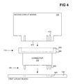
- FIG. 4 shows an example implementation of the form factor of the inter-circuit board connector 102 .
- the first connection mechanism 108 is implemented as a number of physical connection pins 402 .
- the connection pins 402 are insertable into and through corresponding vias 404 of the first circuit board 104 , the thickness of which is depicted in FIG. 4 .
- solder can be applied to permanently affix the inter-circuit board connector 102 to the first circuit board 104 .
- the physical connection pins 402 connect to the power pins 112 , and can also connect to the pins 208 , 210 , and 212 .
- the second connection mechanism 110 of the inter-circuit board connector 102 is implemented as a socket 406 having a slot 408 .
- a corresponding portion 412 of the second circuit board 106 is removably inserted into the slot 408 .
- Conductive traces 410 make electrical connection with the connector 102 inside the slot 408 .
- the second circuit board 106 can thus be removed from the connector 102 in the example of FIG. 4 .
- the conductive traces 410 connect to the power pins 112 , and can also connect to the pins 208 , 210 , and 212 .
- FIG. 5 shows an example implementation of the current sensor 116 of the inter-board circuit board connector 102 that measures the current on the selected power pin 114 .
- the current sensor 116 includes a ferrite core 502 concentrically surrounding the selected power pin 114 , and a Hall effect sensor 504 from which the power input 202 , the ground input 204 , and the signal output 206 extend.
- This implementation thus leverages the Hall effect, which is the production of a voltage difference across an electrical conductor, transverse to current in the conductor and a magnetic field perpendicular to the current.
- the current sensor 116 of the example of FIG. 4 senses the current through the selected power pin 114 non-invasively, without having to be in place in series with the selected power pin 114 .
- FIG. 6 shows an example method 600 for using the inter-board circuit connector 102 to determine the total current transmitted by the first circuit board 104 to the second circuit board 106 over the connector 102 .
- the first connection mechanism 108 of the connector 102 is connected to the first circuit board 104 .
- the second connection mechanism 110 of the connector 102 is connected to the second circuit board 106 . If the current sensor 116 of the connector 102 includes the external connector 302 , the external device 306 may be connected to the sensor 106 via the cable 304 being connected to the external connector 302 .
- the selected circuit board i.e., one of the circuit boards 104 and 106
- the external device 306 receives a signal corresponding to this measured current ( 608 ).
- the electronic component 214 of the selected circuit board or the external device 306 multiplies the measured current by the ratio of the total number of power pins 112 to the number of selected power pins 114 to determine the total current on the power pins 112 ( 610 ).
- the electronic component 214 of the external device 306 then outputs this total current, which is the current that the first circuit board 104 transmits through the inter-circuit board connector 102 to the second circuit board 106 ( 612 ). For instance, the total current may be displayed, and so on.
- the inter-circuit board connector 102 that has been described herein can thus be employed to sense and measure the current that the first circuit board 104 transmits to the second circuit board 104 through the connector 102 . It is further noted that, although specific embodiments have been illustrated and described herein, it will be appreciated by those of ordinary skill in the art that any arrangement calculated to achieve the same purpose may be substituted for the specific embodiments shown. This application is thus intended to cover any adaptations or variations of embodiments of the present invention. As such and therefore, it is manifestly intended that this invention be limited only by the claims and equivalents thereof.
Landscapes
- Physics & Mathematics (AREA)
- General Physics & Mathematics (AREA)
- Engineering & Computer Science (AREA)
- Microelectronics & Electronic Packaging (AREA)
- Power Sources (AREA)
Abstract
Description
Claims (20)
Priority Applications (1)
| Application Number | Priority Date | Filing Date | Title |
|---|---|---|---|
| US14/610,446 US9857398B2 (en) | 2015-01-30 | 2015-01-30 | Inter-circuit board connector with current sensor |
Applications Claiming Priority (1)
| Application Number | Priority Date | Filing Date | Title |
|---|---|---|---|
| US14/610,446 US9857398B2 (en) | 2015-01-30 | 2015-01-30 | Inter-circuit board connector with current sensor |
Publications (2)
| Publication Number | Publication Date |
|---|---|
| US20160223596A1 US20160223596A1 (en) | 2016-08-04 |
| US9857398B2 true US9857398B2 (en) | 2018-01-02 |
Family
ID=56554092
Family Applications (1)
| Application Number | Title | Priority Date | Filing Date |
|---|---|---|---|
| US14/610,446 Active 2035-09-06 US9857398B2 (en) | 2015-01-30 | 2015-01-30 | Inter-circuit board connector with current sensor |
Country Status (1)
| Country | Link |
|---|---|
| US (1) | US9857398B2 (en) |
Cited By (1)
| Publication number | Priority date | Publication date | Assignee | Title |
|---|---|---|---|---|
| US11303064B2 (en) * | 2020-07-10 | 2022-04-12 | Beijing Voyager Technology Co., Ltd. | Methods and apparatuses for aligning and coupling a circuit board with a chassis and another circuit board |
Families Citing this family (4)
| Publication number | Priority date | Publication date | Assignee | Title |
|---|---|---|---|---|
| JP6522048B2 (en) * | 2017-05-31 | 2019-05-29 | 本田技研工業株式会社 | POWER DEVICE AND METHOD FOR MANUFACTURING POWER DEVICE |
| CN110187217B (en) * | 2018-11-30 | 2022-05-13 | 中航光电科技股份有限公司 | Connector for current online detection and active end thereof |
| DE102019213851A1 (en) * | 2019-09-11 | 2021-03-11 | Zf Friedrichshafen Ag | PCB layout |
| US11860702B2 (en) * | 2020-12-15 | 2024-01-02 | International Business Machines Corporation | Current consumption controller |
Citations (19)
| Publication number | Priority date | Publication date | Assignee | Title |
|---|---|---|---|---|
| US3556525A (en) * | 1968-06-12 | 1971-01-19 | Loren Davis Pegg | Electric football game with offensive, defensive, and chance selection means |
| US3566190A (en) * | 1968-12-23 | 1971-02-23 | Raven Ind Inc | Industrial control system with means for releasably securing a plurality of electronic modules |
| US3567998A (en) * | 1968-05-13 | 1971-03-02 | Rca Corp | Corner edge connector for printed circuit boards |
| US3582774A (en) | 1969-03-13 | 1971-06-01 | Ford Motor Co | Circuit impedance measuring device employing clamp on magnetic current sensor |
| US4378525A (en) | 1980-09-18 | 1983-03-29 | Burdick Neal M | Method and apparatus for measuring a DC current in a wire without making a direct connection to the wire |
| US5473244A (en) | 1992-09-17 | 1995-12-05 | Libove; Joel M. | Apparatus for measuring voltages and currents using non-contacting sensors |
| US5602723A (en) * | 1995-03-06 | 1997-02-11 | Fujitsu Limited | Subrack device |
| US6175230B1 (en) * | 1999-01-14 | 2001-01-16 | Genrad, Inc. | Circuit-board tester with backdrive-based burst timing |
| US6426617B1 (en) * | 1999-09-28 | 2002-07-30 | Rockwell Automation Technologies, Inc. | Hall effect current sensor system packaging |
| US20060219436A1 (en) | 2003-08-26 | 2006-10-05 | Taylor William P | Current sensor |
| US20070170533A1 (en) | 2006-01-20 | 2007-07-26 | Allegro Microsystems, Inc. | Arrangements for an intergrated sensor |
| US20070279053A1 (en) | 2006-05-12 | 2007-12-06 | Taylor William P | Integrated current sensor |
| US20080013298A1 (en) | 2006-07-14 | 2008-01-17 | Nirmal Sharma | Methods and apparatus for passive attachment of components for integrated circuits |
| US8058876B2 (en) | 2008-04-24 | 2011-11-15 | Honeywell International, Inc. | Low cost current and temperature sensor |
| US20120074929A1 (en) | 2010-09-27 | 2012-03-29 | Darold Wobschall | Inductive Current Sensor |
| US20130258624A1 (en) * | 2012-03-29 | 2013-10-03 | Keith Bryan Hardin | Ball grid array systems for surface mounting an integrated circuit using a z-directed printed circuit board component |
| US20130265076A1 (en) * | 2012-04-10 | 2013-10-10 | Hon Hai Precision Industry Co., Ltd. | Adapter board and dc power supply test system using same |
| US8723515B2 (en) | 2012-07-05 | 2014-05-13 | Infineon Technologies Ag | Vertical hall sensor circuit comprising stress compensation circuit |
| US20140203803A1 (en) | 2013-01-20 | 2014-07-24 | International Business Machines Corporation | Current detector to sense current without being in series with conductor |
-
2015
- 2015-01-30 US US14/610,446 patent/US9857398B2/en active Active
Patent Citations (19)
| Publication number | Priority date | Publication date | Assignee | Title |
|---|---|---|---|---|
| US3567998A (en) * | 1968-05-13 | 1971-03-02 | Rca Corp | Corner edge connector for printed circuit boards |
| US3556525A (en) * | 1968-06-12 | 1971-01-19 | Loren Davis Pegg | Electric football game with offensive, defensive, and chance selection means |
| US3566190A (en) * | 1968-12-23 | 1971-02-23 | Raven Ind Inc | Industrial control system with means for releasably securing a plurality of electronic modules |
| US3582774A (en) | 1969-03-13 | 1971-06-01 | Ford Motor Co | Circuit impedance measuring device employing clamp on magnetic current sensor |
| US4378525A (en) | 1980-09-18 | 1983-03-29 | Burdick Neal M | Method and apparatus for measuring a DC current in a wire without making a direct connection to the wire |
| US5473244A (en) | 1992-09-17 | 1995-12-05 | Libove; Joel M. | Apparatus for measuring voltages and currents using non-contacting sensors |
| US5602723A (en) * | 1995-03-06 | 1997-02-11 | Fujitsu Limited | Subrack device |
| US6175230B1 (en) * | 1999-01-14 | 2001-01-16 | Genrad, Inc. | Circuit-board tester with backdrive-based burst timing |
| US6426617B1 (en) * | 1999-09-28 | 2002-07-30 | Rockwell Automation Technologies, Inc. | Hall effect current sensor system packaging |
| US20060219436A1 (en) | 2003-08-26 | 2006-10-05 | Taylor William P | Current sensor |
| US20070170533A1 (en) | 2006-01-20 | 2007-07-26 | Allegro Microsystems, Inc. | Arrangements for an intergrated sensor |
| US20070279053A1 (en) | 2006-05-12 | 2007-12-06 | Taylor William P | Integrated current sensor |
| US20080013298A1 (en) | 2006-07-14 | 2008-01-17 | Nirmal Sharma | Methods and apparatus for passive attachment of components for integrated circuits |
| US8058876B2 (en) | 2008-04-24 | 2011-11-15 | Honeywell International, Inc. | Low cost current and temperature sensor |
| US20120074929A1 (en) | 2010-09-27 | 2012-03-29 | Darold Wobschall | Inductive Current Sensor |
| US20130258624A1 (en) * | 2012-03-29 | 2013-10-03 | Keith Bryan Hardin | Ball grid array systems for surface mounting an integrated circuit using a z-directed printed circuit board component |
| US20130265076A1 (en) * | 2012-04-10 | 2013-10-10 | Hon Hai Precision Industry Co., Ltd. | Adapter board and dc power supply test system using same |
| US8723515B2 (en) | 2012-07-05 | 2014-05-13 | Infineon Technologies Ag | Vertical hall sensor circuit comprising stress compensation circuit |
| US20140203803A1 (en) | 2013-01-20 | 2014-07-24 | International Business Machines Corporation | Current detector to sense current without being in series with conductor |
Cited By (1)
| Publication number | Priority date | Publication date | Assignee | Title |
|---|---|---|---|---|
| US11303064B2 (en) * | 2020-07-10 | 2022-04-12 | Beijing Voyager Technology Co., Ltd. | Methods and apparatuses for aligning and coupling a circuit board with a chassis and another circuit board |
Also Published As
| Publication number | Publication date |
|---|---|
| US20160223596A1 (en) | 2016-08-04 |
Similar Documents
| Publication | Publication Date | Title |
|---|---|---|
| US9857398B2 (en) | Inter-circuit board connector with current sensor | |
| US20130265076A1 (en) | Adapter board and dc power supply test system using same | |
| US20160047855A1 (en) | Pcb authentication and counterfeit detection | |
| CN101458289A (en) | Motherboard line detection device | |
| US9482700B2 (en) | Current detector to sense current without being in series with conductor | |
| CN110716120B (en) | Calibration method for channel delay deviation of automatic chip test equipment | |
| US8441273B2 (en) | Testing card and testing system for USB port | |
| CN104749542A (en) | Calibration and operation method of detection system | |
| US9857420B2 (en) | Method for determining a condition of pin connection of the integrated circuit and integrated circuit thereof | |
| US11249145B2 (en) | Magnetic field sensing | |
| CN202815137U (en) | Electrical connecting component | |
| CN108535535B (en) | A kind of current detection method and system for integrated chip | |
| US6919813B2 (en) | Built-in circuitry and method to test connector loading | |
| CN117491738B (en) | Chip socket mounting contact resistance testing device and method | |
| CN103901249A (en) | Interface signal test device | |
| US9622336B2 (en) | Releasable probe connection | |
| KR200461065Y1 (en) | Electronic watt hour meter | |
| CN113009223B (en) | Impedance measuring method | |
| CN219811169U (en) | Computing device | |
| EP2629324A2 (en) | Method and apparatus for attachment of integrated circuits | |
| CN104482850A (en) | PCB drill precision detection method | |
| US20130063124A1 (en) | Measurement card | |
| US9958496B2 (en) | Layer-layer registration coupon for printed circuit boards | |
| US9081056B2 (en) | Method for detecting working state of I/O pins of electronic components using charges from human body | |
| US8421490B2 (en) | Loading card for measuring voltages |
Legal Events
| Date | Code | Title | Description |
|---|---|---|---|
| AS | Assignment |
Owner name: LENOVO ENTERPRISE SOLUTIONS (SINGAPORE) PTE. LTD., Free format text: ASSIGNMENT OF ASSIGNORS INTEREST;ASSIGNOR:MENG, JIAN;REEL/FRAME:034856/0601 Effective date: 20150123 |
|
| STCF | Information on status: patent grant |
Free format text: PATENTED CASE |
|
| AS | Assignment |
Owner name: LENOVO GLOBAL TECHNOLOGIES INTERNATIONAL LTD, HONG Free format text: ASSIGNMENT OF ASSIGNORS INTEREST;ASSIGNOR:LENOVO ENTERPRISE SOLUTIONS (SINGAPORE) PTE LTD.;REEL/FRAME:050309/0564 Effective date: 20180401 |
|
| MAFP | Maintenance fee payment |
Free format text: PAYMENT OF MAINTENANCE FEE, 4TH YEAR, LARGE ENTITY (ORIGINAL EVENT CODE: M1551); ENTITY STATUS OF PATENT OWNER: LARGE ENTITY Year of fee payment: 4 |
|
| AS | Assignment |
Owner name: LENOVO GLOBAL TECHNOLOGIES SWITZERLAND INTERNATIONAL GMBH, SWITZERLAND Free format text: ASSIGNMENT OF ASSIGNORS INTEREST;ASSIGNOR:LENOVO GLOBAL TECHNOLOGIES INTERNATIONAL LIMITED;REEL/FRAME:069869/0614 Effective date: 20241231 |
|
| MAFP | Maintenance fee payment |
Free format text: PAYMENT OF MAINTENANCE FEE, 8TH YEAR, LARGE ENTITY (ORIGINAL EVENT CODE: M1552); ENTITY STATUS OF PATENT OWNER: LARGE ENTITY Year of fee payment: 8 |