US9852662B2 - Beverage tag - Google Patents

Beverage tag Download PDF

Info

Publication number
US9852662B2
US9852662B2 US14/961,008 US201514961008A US9852662B2 US 9852662 B2 US9852662 B2 US 9852662B2 US 201514961008 A US201514961008 A US 201514961008A US 9852662 B2 US9852662 B2 US 9852662B2
Authority
US
United States
Prior art keywords
beverage
identification
section
rotation
identification device
Prior art date
Legal status (The legal status is an assumption and is not a legal conclusion. Google has not performed a legal analysis and makes no representation as to the accuracy of the status listed.)
Active
Application number
US14/961,008
Other versions
US20170162081A1 (en
Inventor
Lori L. Williams
Current Assignee (The listed assignees may be inaccurate. Google has not performed a legal analysis and makes no representation or warranty as to the accuracy of the list.)
Buttn Products Inc D/b/a Brew Buttn
Buttn Products Inc
Original Assignee
Buttn Products Inc
Priority date (The priority date is an assumption and is not a legal conclusion. Google has not performed a legal analysis and makes no representation as to the accuracy of the date listed.)
Filing date
Publication date
Application filed by Buttn Products Inc filed Critical Buttn Products Inc
Priority to US14/961,008 priority Critical patent/US9852662B2/en
Publication of US20170162081A1 publication Critical patent/US20170162081A1/en
Assigned to BUTTN PRODUCTS, INC. D/B/A BREW BUTTN reassignment BUTTN PRODUCTS, INC. D/B/A BREW BUTTN ASSIGNMENT OF ASSIGNORS INTEREST (SEE DOCUMENT FOR DETAILS). Assignors: WILLIAMS, LORI L.
Application granted granted Critical
Publication of US9852662B2 publication Critical patent/US9852662B2/en
Active legal-status Critical Current
Anticipated expiration legal-status Critical

Links

Images

Classifications

    • GPHYSICS
    • G09EDUCATION; CRYPTOGRAPHY; DISPLAY; ADVERTISING; SEALS
    • G09FDISPLAYING; ADVERTISING; SIGNS; LABELS OR NAME-PLATES; SEALS
    • G09F3/00Labels, tag tickets, or similar identification or indication means; Seals; Postage or like stamps
    • G09F3/02Forms or constructions
    • GPHYSICS
    • G09EDUCATION; CRYPTOGRAPHY; DISPLAY; ADVERTISING; SEALS
    • G09FDISPLAYING; ADVERTISING; SIGNS; LABELS OR NAME-PLATES; SEALS
    • G09F23/00Advertising on or in specific articles, e.g. ashtrays, letter-boxes
    • G09F23/06Advertising on or in specific articles, e.g. ashtrays, letter-boxes the advertising matter being combined with articles for restaurants, shops or offices
    • G09F23/08Advertising on or in specific articles, e.g. ashtrays, letter-boxes the advertising matter being combined with articles for restaurants, shops or offices with tableware
    • AHUMAN NECESSITIES
    • A47FURNITURE; DOMESTIC ARTICLES OR APPLIANCES; COFFEE MILLS; SPICE MILLS; SUCTION CLEANERS IN GENERAL
    • A47GHOUSEHOLD OR TABLE EQUIPMENT
    • A47G19/00Table service
    • A47G19/22Drinking vessels or saucers used for table service
    • A47G19/2205Drinking glasses or vessels
    • A47G19/2227Drinking glasses or vessels with means for amusing or giving information to the user
    • GPHYSICS
    • G09EDUCATION; CRYPTOGRAPHY; DISPLAY; ADVERTISING; SEALS
    • G09FDISPLAYING; ADVERTISING; SIGNS; LABELS OR NAME-PLATES; SEALS
    • G09F11/00Indicating arrangements for variable information in which the complete information is permanently attached to a movable support which brings it to the display position
    • G09F11/23Indicating arrangements for variable information in which the complete information is permanently attached to a movable support which brings it to the display position the advertising or display material forming part of rotating members, e.g. in the form of perforations, prints, or transparencies on a drum or disc
    • G09F11/232Disc card or folded disc shaped card information display devices
    • GPHYSICS
    • G09EDUCATION; CRYPTOGRAPHY; DISPLAY; ADVERTISING; SEALS
    • G09FDISPLAYING; ADVERTISING; SIGNS; LABELS OR NAME-PLATES; SEALS
    • G09F3/00Labels, tag tickets, or similar identification or indication means; Seals; Postage or like stamps
    • G09F3/08Fastening or securing by means not forming part of the material of the label itself
    • G09F3/16Fastening or securing by means not forming part of the material of the label itself by clamps
    • GPHYSICS
    • G09EDUCATION; CRYPTOGRAPHY; DISPLAY; ADVERTISING; SEALS
    • G09FDISPLAYING; ADVERTISING; SIGNS; LABELS OR NAME-PLATES; SEALS
    • G09F3/00Labels, tag tickets, or similar identification or indication means; Seals; Postage or like stamps
    • G09F3/02Forms or constructions
    • G09F2003/0272Labels for containers

Definitions

  • the invention relates to an identification device and, more particularly, to a beverage identification device.
  • beverages such as soft drinks, alcoholic beverages, and brewed beverages. Because these beverages are generally not often visually distinguished by brand, the customer cannot always positively identify beverages he or she likes in the container which the beverage is served. Furthermore, with the increasing competition between specialized beverages, such as beers and wines, manufacturers need a way to distinguish their products from the competition.
  • a beverage identification device has an identification member, a rotation member rotatably attached to the identification member, and an attachment mechanism extending from the identification member.
  • FIG. 1 is a perspective view of a beverage identification device according to the invention, shown attached to a known beverage container;
  • FIG. 2 is a side view of the beverage identification device of FIG. 1 ;
  • FIG. 3 is a front perspective view of a beverage identification device according to the invention.
  • FIG. 4 is a rear perspective view of the beverage identification device of FIG. 3 ;
  • FIG. 5 is another perspective view of a beverage identification device according to the invention, showing an attachment mechanism removed therefrom;
  • FIG. 6 is a perspective view of the attachment mechanism of FIG. 5 ;
  • FIG. 7 is a front view of the attachment mechanism of FIG. 5 ;
  • FIG. 8 is a rear view a beverage identification device according to the invention, showing a rotation member rotatably positioned about an identification member;
  • FIG. 9 is another rear view the beverage identification device of FIG. 8 , showing the rotation member further rotated about the identification member;
  • FIG. 10 is yet another rear view the beverage identification device of FIG. 8 , further showing rotation of the rotation member about the identification member;
  • FIG. 11 is an exploded perspective view of a beverage identification device according to the invention.
  • FIG. 12 is sectional view of the beverage identification device of FIG. 4 , taken along line 12 - 12 ;
  • FIG. 13 is sectional view of the beverage identification device of FIG. 12 , taken along line 13 - 13 ;
  • FIG. 14 is sectional view of the beverage identification device of FIG. 12 , taken along line 14 - 14 ;
  • FIG. 15 is sectional view of the beverage identification device of FIG. 12 , taken along line 15 - 15 .
  • a beverage identification device 1 for a beverage container 2 is provided.
  • the beverage identification device 1 generally has a rotation member 10 , an identification member 40 , and an attachment mechanism 70 .
  • the rotation member 10 is a flat planar member.
  • the rotation member 10 is a disc shaped member.
  • the rotation member could have other polygonal shapes.
  • the rotation member 10 generally has a front side 12 , an information display 14 , a rear side 16 , a rotation member viewing section 34 , and an outer wall 38 .
  • the front side 12 is a flat planar surface outside of the beverage identification device 1 .
  • the information display 14 is positioned along the front side 12 .
  • the information display 14 is a display of printed indicia, engraved advertisements, or other product information.
  • the information display 14 may have product information, website information, or other information for a consumer of beverages.
  • the information display 14 may also be a decal that is disposed along the planar surface of the front side 12 .
  • the rear side 16 is opposite the front side 12 and generally has a recessed section 18 , a rotation device receiving passageway 20 , and a flange 22 .
  • the recessed section 18 is a depression extending from an outer surface of the rear side 16 and toward the front side 12 .
  • the recessed section 18 is circular shaped and provides the flange 22 along an outer perimeter thereof.
  • the rear side 16 may be planar and without a recessed section as shown.
  • the flange 22 is a flat rim positioned along the outer perimeter of the rear side 16 .
  • the flange 22 provides a flat surface on which the identification member 40 rotates.
  • the flange 22 has a positioning member 26 having one or more protrusions 28 extending outward from the flange 22 .
  • the flange 22 has one protrusion 28 that is a cylindrical protuberance in an exemplary embodiment.
  • the protrusion 28 is sized and shaped to correspond with a plurality of protrusion receiving passageways 62 that are positioned on the identification member 40 (described in further detail below).
  • a plurality of protrusion receiving passageways 62 that are positioned on the identification member 40 (described in further detail below).
  • the positioning member 26 may have a plurality of depressions (not shown) that extend inward from a top surface of the flange 22 . Each depression would be sized and shaped to correspond with one or more protuberances positioned on the identification member 40 .
  • the rotation device receiving passageway 20 has a pin receiving passageway 21 a and a catch receiving section 21 d .
  • the pin receiving passageway 21 a and the catch receiving section 21 d are positioned and shaped to correspond with a rotation device 50 of the identification member 40 (described in more detail below).
  • the rotation device receiving passageway 20 is positioned about a proximate center of the rear side 16 and, more particularly, about a proximate center of the recessed section 18 .
  • the pin receiving passageway 21 a is a cylindrical opening extending from the rear side 16 toward the front side 12 .
  • the pin receiving passageway 21 a does not extend completely through the rotation member 10 , but to a center section thereof.
  • the catch receiving section 21 d is doughnut shaped receiving section positioned in the pin receiving passageway 21 a and extends laterally with respect to the a longitudinal length of the pin receiving passageway 21 a .
  • the catch receiving section 21 d is positioned about a middle section of the pin receiving passageway 21 a.
  • the shape, size and placement of the pin receiving passageway 21 a and a catch receiving section 21 d may change depending of the shape, size and placement of the rotation device 50 .
  • the rotation member viewing section 34 is an opening along the front side 12 and extends through a major surface of the rear side 16 .
  • the rotation member viewing section 34 has an inner wall 36 that provide a through hole extending completely through the rotation member 10 .
  • the rotation member viewing section 34 is kidney shaped. However, one skilled in the art should appreciate that other designs and shapes are possible.
  • a transparent material may be positioned over the rotation member viewing section 34 .
  • the outer wall 38 extends along an outer perimeter of the rotation member 10 .
  • the outer wall 38 extends between the front side 12 and the rear side 16 .
  • the outer wall 38 has knurled or reeded edges 39 for grip.
  • the outer wall 38 may have one or more depressions or protuberances to provide relief along the outer edge of the rotation member 10 .
  • the identification member 40 generally has a front side 42 , a rating device 48 , a rotation device 50 , a rear side 66 , and an outer wall 68 .
  • the front side 42 is a flat planar surface positioned on an inner section of the beverage identification device 1 .
  • the front side 42 has an attachment mechanism receiving section 44 , a recessed section 46 , and a flange 58 .
  • the recessed section 46 is a depression extending from an outer surface of the front side 42 toward the rear side 66 .
  • the recessed section 46 is circular shaped.
  • the recessed section 46 provides the flange 58 .
  • the front side 42 may shaped and sized differently.
  • the flange 58 is a projecting flat surface rim positioned along an outer perimeter of the front side 42 .
  • the flange 58 provides a surface on which the rotation member 10 rotates.
  • the flange 58 has a positioning member 60 which is one or more protrusion receiving passageways 62 that extend inward from the flange 58 .
  • the flange 58 has three protrusion receiving passageways 62 that are cylindrical depressions.
  • the protrusion receiving passageways 62 are sized and shaped to corresponding with a plurality of protrusions 28 positioned on the rotation member 10 .
  • One skilled in the art should appreciate that other design are possible.
  • the positioning member 60 may have a plurality of protrusions (not shown) extending outward from a top surface of the flange 58 .
  • Each protrusion would be sized and shaped to corresponding with one or more depressions positioned on the rotation member 10 .
  • the attachment mechanism receiving section 44 is a depression extending further from the outer surface of the front side 42 toward the rear side 66 .
  • the attachment mechanism receiving section 44 is boxed shaped and corresponds to the attachment mechanism 70 .
  • the attachment mechanism receiving section 44 may be shaped and sized differently.
  • the rating device 48 is provided and positioned along a major surface of the recessed section 46 .
  • the rating device 48 has a plurality of grouped raised indicia 49 for classification purposes.
  • a grouping of stars is used for the plurality of grouped raised indicia 49 so the user can rank characteristics of the beverage.
  • one to five stars may be employed to categorize the beverage on appearance, aroma, palate, flavor, quality, or the overall impression, as well as any other the characteristic left to the discretion of the individual user.
  • a number system may be used, or the indicia can be a set of stickers positioned on the major surface of the recessed section 46 .
  • the rotation device 50 is positioned along a major surface of the recessed section 46 and, more particularly, outward from the attachment mechanism receiving section 44 .
  • the rotation device 50 generally has an extension 52 , an extension support 54 , and a stop 56 in the embodiment shown.
  • the extension 52 extends outward from the attachment mechanism receiving section 44 and is positioned perpendicular to the outer surface of the front side 42 .
  • the extension 52 is a cylindrical pin in the embodiment shown.
  • the extension support 54 is provided along a proximal end of the extension 52 .
  • the extension support 54 is a weld extending around the extension 52 to provide support and rigidity.
  • the extension support 54 is integrally formed with the extension 52 .
  • one skilled in the art should appreciate that other designs are possible.
  • the rotation device 50 further has the stop 56 positioned along a distal end of the extension 52 .
  • the stop 56 is a catch extending about the extension and, in the shown embodiment, doughnut shaped.
  • the stop 56 is integrally formed with extension and approximately positioned inward from the distal end.
  • the stop 56 is shaped and sized to correspond with the catch receiving section 21 d . Therefore, the stop 56 and the catch receiving section 21 d are keyed to one another, as shown.
  • the primary indicia 67 are positioned along the rear side 66 .
  • the primary indicia 67 are a display of printed indicia or engraved advertisements or information.
  • the primary indicia 67 may have a trademark, product information, website information, or other information for the consumer concerning the beverage.
  • the primary indicia 67 may also be a decal that is disposed along the planar surface of the rear side 66 .
  • the outer wall 68 is positioned along an outer perimeter of the rotation member 10 .
  • the outer wall 68 extends between the front side 42 and the rear side 66 .
  • the outer wall 68 has reeded edges 69 for grip.
  • the outer wall 68 may have one or more depressions or protuberances to provide relief along the outer edge of the rotation member 10 .
  • the attachment mechanism 70 generally has a container connector section 72 , a member connector section 78 , and a connection section 84 .
  • the attachment mechanism 70 is removable from the identification member 40 .
  • the attachment mechanism 70 may be permanently secured within the identification member 40 or held by the rotation device 50 .
  • the container connector section 72 has a pair of resilient outer arms 74 and rigid base 76 connecting the pair of resilient outer arms 74 along a proximal end of the attachment mechanism 70 .
  • the pair of resilient outer arms 74 extend parallel to each other and are inwardly elastic in the embodiment shown. For instance, the pair of resilient outer arms 74 can be moved toward each other.
  • the container connection section 72 may be a single arm.
  • the container connector section 72 may be other known means of removable connectors, including fasteners, adhesives, etc.
  • a width of the container connector section 72 is approximately the same as the attachment mechanism receiving section 44 .
  • the member connector section 78 has a pair of resilient inner arms 80 and rigid base 82 connecting the pair of resilient inner arms 80 along a distal end of the attachment mechanism 70 .
  • the pair of resilient inner arms 80 extend parallel to each other and are inwardly elastic in the embodiment shown. For instance, the pair of resilient inner arms 80 can be moved toward each other. As shown, the pair of resilient inner arms 80 are angled with respect to the pair of resilient outer arms 74 .
  • the member connector section 78 may be a single arm connected to the pair of resilient outer arms 74 .
  • the member connector section 78 may be other known means of connection, including fasteners, adhesives, etc.
  • connection section 84 has a pair of connecting arms 86 connecting the pair of resilient inner and outer arms 74 , 80 .
  • the pair of resilient connecting arms 86 extend parallel to each other and are inwardly elastic in the embodiment shown. For instance, the pair of resilient connecting arms 86 can be moved toward each other.
  • the pair of resilient connecting arms 86 are u-shaped such that the pair of resilient outer arms 74 and the pair of resilient inner arms 80 are angled with respect to each other.
  • the connection section 84 may be a single arm connected to the container connector section 72 and the member connector section 78 . In other embodiments, the container connector section 72 and the member connector section 78 can be directly connected to each other.
  • the rotation member 10 and the identification member 40 are connected together using the rotation device 50 and the rotation device receiving passageway 20 .
  • the flange 22 along the rear side 16 of the rotation member 10 is positioned on the flange 58 of the front side 42 of the identification member 40 .
  • the rotation device 50 is positioned in the rotation device receiving passageway 20 .
  • the extension 52 is positioned through the pin receiving passageway 21 a and the stop 56 is received by the catch receiving section 21 d to hold the extension 52 in the pin receiving passageway 21 a .
  • the rotation member 10 abuts the identification member 40 and is allowed to rotate there about.
  • the positioning member 26 is positioned in one of the plurality of protrusion receiving passageways 62 positioned on the identification member 40 and one of the raised indicia 49 of the rating device 48 is visible through the rotation member viewing section 34 .
  • the member connector section 78 is then positioned in the attachment mechanism receiving section 44 and held in the identification member 40 by a friction fit connection in the shown embodiment.
  • the attachment mechanism 70 may be secured to the identification member 40 using various known connection means, including fasteners, adhesives, etc.
  • a server positions the beverage identification device 1 on the beverage container 2 using the attachment mechanism 70 .
  • the container connector section 72 is united with the beverage container 2 and, more particularly, hung from a rim of the beverage container 2 .
  • the attachment mechanism 70 may be united with the beverage container 2 using various known connection means, including fasteners, adhesives, etc.
  • the user can remove the identification device 1 from the beverage container 2 and review information concerning the beverage in the beverage container 2 using the information display 14 and the primary indicia 67 .
  • the user can remove the attachment mechanism 70 for disposal and collect several beverage identification devices 1 for further review at a later time.

Landscapes

  • Physics & Mathematics (AREA)
  • General Physics & Mathematics (AREA)
  • Engineering & Computer Science (AREA)
  • Theoretical Computer Science (AREA)
  • Details Of Rigid Or Semi-Rigid Containers (AREA)

Abstract

A beverage identification device is provided and generally has an identification member, a rotation member rotatably attached to the identification member, and an attachment mechanism extending from the identification member.

Description

FIELD OF THE INVENTION
The invention relates to an identification device and, more particularly, to a beverage identification device.
BACKGROUND
Many restaurants, bars, and other food eating establishments provide beverages, such as soft drinks, alcoholic beverages, and brewed beverages. Because these beverages are generally not often visually distinguished by brand, the customer cannot always positively identify beverages he or she likes in the container which the beverage is served. Furthermore, with the increasing competition between specialized beverages, such as beers and wines, manufacturers need a way to distinguish their products from the competition.
SUMMARY
Accordingly, a beverage identification device is provided and has an identification member, a rotation member rotatably attached to the identification member, and an attachment mechanism extending from the identification member.
BRIEF DESCRIPTION OF THE DRAWINGS
The invention will now be described by way of example with reference to the accompanying Figures, of which:
FIG. 1 is a perspective view of a beverage identification device according to the invention, shown attached to a known beverage container;
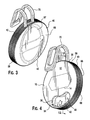
FIG. 2 is a side view of the beverage identification device of FIG. 1;
FIG. 3 is a front perspective view of a beverage identification device according to the invention;
FIG. 4 is a rear perspective view of the beverage identification device of FIG. 3;
FIG. 5 is another perspective view of a beverage identification device according to the invention, showing an attachment mechanism removed therefrom;
FIG. 6 is a perspective view of the attachment mechanism of FIG. 5;
FIG. 7 is a front view of the attachment mechanism of FIG. 5;
FIG. 8 is a rear view a beverage identification device according to the invention, showing a rotation member rotatably positioned about an identification member;
FIG. 9 is another rear view the beverage identification device of FIG. 8, showing the rotation member further rotated about the identification member;
FIG. 10 is yet another rear view the beverage identification device of FIG. 8, further showing rotation of the rotation member about the identification member;
FIG. 11 is an exploded perspective view of a beverage identification device according to the invention;
FIG. 12 is sectional view of the beverage identification device of FIG. 4, taken along line 12-12;
FIG. 13 is sectional view of the beverage identification device of FIG. 12, taken along line 13-13;
FIG. 14 is sectional view of the beverage identification device of FIG. 12, taken along line 14-14; and
FIG. 15 is sectional view of the beverage identification device of FIG. 12, taken along line 15-15.
DETAILED DESCRIPTION OF THE EMBODIMENT(S)
In an exemplary embodiment, as shown in the Figures, a beverage identification device 1 for a beverage container 2 is provided.
As shown, the beverage identification device 1 generally has a rotation member 10, an identification member 40, and an attachment mechanism 70.
Now with respect to FIGS. 4 through 11, the rotation member 10 will be described. The rotation member 10 is a flat planar member. In particular, in the shown embodiment, the rotation member 10 is a disc shaped member. However, one skilled in the art should appreciate that the rotation member could have other polygonal shapes.
As shown in the Figures, the rotation member 10 generally has a front side 12, an information display 14, a rear side 16, a rotation member viewing section 34, and an outer wall 38.
The front side 12 is a flat planar surface outside of the beverage identification device 1.
The information display 14 is positioned along the front side 12. The information display 14 is a display of printed indicia, engraved advertisements, or other product information. For instance, the information display 14 may have product information, website information, or other information for a consumer of beverages. The information display 14 may also be a decal that is disposed along the planar surface of the front side 12.
The rear side 16 is opposite the front side 12 and generally has a recessed section 18, a rotation device receiving passageway 20, and a flange 22.
As shown in FIG. 11, the recessed section 18 is a depression extending from an outer surface of the rear side 16 and toward the front side 12. In the shown embodiment, the recessed section 18 is circular shaped and provides the flange 22 along an outer perimeter thereof. However, one skilled in the art should appreciate that other design are possible and the rear side 16 may be planar and without a recessed section as shown.
As shown in FIG. 11, the flange 22 is a flat rim positioned along the outer perimeter of the rear side 16. The flange 22 provides a flat surface on which the identification member 40 rotates. The flange 22 has a positioning member 26 having one or more protrusions 28 extending outward from the flange 22. As shown, the flange 22 has one protrusion 28 that is a cylindrical protuberance in an exemplary embodiment. The protrusion 28 is sized and shaped to correspond with a plurality of protrusion receiving passageways 62 that are positioned on the identification member 40 (described in further detail below). One skilled in the art should appreciate that other designs are possible. For instance, the positioning member 26 may have a plurality of depressions (not shown) that extend inward from a top surface of the flange 22. Each depression would be sized and shaped to correspond with one or more protuberances positioned on the identification member 40.
As shown in FIG. 11-13, the rotation device receiving passageway 20 has a pin receiving passageway 21 a and a catch receiving section 21 d. The pin receiving passageway 21 a and the catch receiving section 21 d are positioned and shaped to correspond with a rotation device 50 of the identification member 40 (described in more detail below).
In the shown exemplary embodiment, the rotation device receiving passageway 20 is positioned about a proximate center of the rear side 16 and, more particularly, about a proximate center of the recessed section 18. The pin receiving passageway 21 a is a cylindrical opening extending from the rear side 16 toward the front side 12. However, in the shown embodiment, the pin receiving passageway 21 a does not extend completely through the rotation member 10, but to a center section thereof. In the shown embodiment, the catch receiving section 21 d is doughnut shaped receiving section positioned in the pin receiving passageway 21 a and extends laterally with respect to the a longitudinal length of the pin receiving passageway 21 a. The catch receiving section 21 d is positioned about a middle section of the pin receiving passageway 21 a.
However, one skilled in the art should appreciate that other designs are possible. For instance, the shape, size and placement of the pin receiving passageway 21 a and a catch receiving section 21 d may change depending of the shape, size and placement of the rotation device 50.
As shown in FIGS. 4 through 11, the rotation member viewing section 34 is an opening along the front side 12 and extends through a major surface of the rear side 16. The rotation member viewing section 34 has an inner wall 36 that provide a through hole extending completely through the rotation member 10. In the embodiment shown, the rotation member viewing section 34 is kidney shaped. However, one skilled in the art should appreciate that other designs and shapes are possible. Furthermore, a transparent material may be positioned over the rotation member viewing section 34.
As shown in FIGS. 1-11, the outer wall 38 extends along an outer perimeter of the rotation member 10. The outer wall 38 extends between the front side 12 and the rear side 16. In the shown embodiment, the outer wall 38 has knurled or reeded edges 39 for grip. However, one skilled in the art should appreciate the other design are possible. For instance, the outer wall 38 may have one or more depressions or protuberances to provide relief along the outer edge of the rotation member 10.
Now with respect to FIGS. 1-3 and 11-15, the identification member 40 will be described.
In an exemplary embodiment of the invention, the identification member 40 generally has a front side 42, a rating device 48, a rotation device 50, a rear side 66, and an outer wall 68.
The front side 42 is a flat planar surface positioned on an inner section of the beverage identification device 1. In the shown embodiment, the front side 42 has an attachment mechanism receiving section 44, a recessed section 46, and a flange 58.
As shown in FIG. 11, the recessed section 46 is a depression extending from an outer surface of the front side 42 toward the rear side 66. In the shown embodiment, the recessed section 46 is circular shaped. The recessed section 46 provides the flange 58. However, one skilled in the art should appreciate that other design are possible and the front side 42 may shaped and sized differently.
As shown in FIG. 11, the flange 58 is a projecting flat surface rim positioned along an outer perimeter of the front side 42. The flange 58 provides a surface on which the rotation member 10 rotates. The flange 58 has a positioning member 60 which is one or more protrusion receiving passageways 62 that extend inward from the flange 58. As shown, the flange 58 has three protrusion receiving passageways 62 that are cylindrical depressions. The protrusion receiving passageways 62 are sized and shaped to corresponding with a plurality of protrusions 28 positioned on the rotation member 10. One skilled in the art should appreciate that other design are possible. For instance, the positioning member 60 may have a plurality of protrusions (not shown) extending outward from a top surface of the flange 58. Each protrusion would be sized and shaped to corresponding with one or more depressions positioned on the rotation member 10.
As shown in FIG. 11, the attachment mechanism receiving section 44 is a depression extending further from the outer surface of the front side 42 toward the rear side 66. In the shown embodiment, the attachment mechanism receiving section 44 is boxed shaped and corresponds to the attachment mechanism 70. However, one skilled in the art should appreciate that other design are possible and the attachment mechanism receiving section 44 may shaped and sized differently.
As shown in FIG. 11, the rating device 48 is provided and positioned along a major surface of the recessed section 46. In the shown embodiment, the rating device 48 has a plurality of grouped raised indicia 49 for classification purposes. As shown, a grouping of stars is used for the plurality of grouped raised indicia 49 so the user can rank characteristics of the beverage. For example, one to five stars may be employed to categorize the beverage on appearance, aroma, palate, flavor, quality, or the overall impression, as well as any other the characteristic left to the discretion of the individual user. One skilled in the art should appreciate that other shapes and rating systems known to the art are possible. For instance, a number system may be used, or the indicia can be a set of stickers positioned on the major surface of the recessed section 46.
As shown in FIG. 11, the rotation device 50 is positioned along a major surface of the recessed section 46 and, more particularly, outward from the attachment mechanism receiving section 44. The rotation device 50 generally has an extension 52, an extension support 54, and a stop 56 in the embodiment shown. As shown, the extension 52 extends outward from the attachment mechanism receiving section 44 and is positioned perpendicular to the outer surface of the front side 42. The extension 52 is a cylindrical pin in the embodiment shown.
In the embodiment shown, the extension support 54 is provided along a proximal end of the extension 52. The extension support 54 is a weld extending around the extension 52 to provide support and rigidity. As shown, the extension support 54 is integrally formed with the extension 52. However, one skilled in the art should appreciate that other designs are possible.
As shown in FIG. 11, the rotation device 50 further has the stop 56 positioned along a distal end of the extension 52. The stop 56 is a catch extending about the extension and, in the shown embodiment, doughnut shaped. The stop 56 is integrally formed with extension and approximately positioned inward from the distal end. One skilled in the art should appreciate that other design are possible. For instance, the stop 56 is shaped and sized to correspond with the catch receiving section 21 d. Therefore, the stop 56 and the catch receiving section 21 d are keyed to one another, as shown.
The primary indicia 67 are positioned along the rear side 66. The primary indicia 67 are a display of printed indicia or engraved advertisements or information. For instance, the primary indicia 67 may have a trademark, product information, website information, or other information for the consumer concerning the beverage. The primary indicia 67 may also be a decal that is disposed along the planar surface of the rear side 66.
As shown in FIGS. 1-11, the outer wall 68 is positioned along an outer perimeter of the rotation member 10. The outer wall 68 extends between the front side 42 and the rear side 66. In the shown embodiment, the outer wall 68 has reeded edges 69 for grip. However, one skilled in the art should appreciate the other design are possible. For instance, the outer wall 68 may have one or more depressions or protuberances to provide relief along the outer edge of the rotation member 10.
Now with reference to FIGS. 5-7, the attachment mechanism 70 will be described. In the embodiment shown, the attachment mechanism 70 generally has a container connector section 72, a member connector section 78, and a connection section 84. In the shown embodiment, the attachment mechanism 70 is removable from the identification member 40. However, one skilled in the art should appreciate that the other designs are possible. For instance, the attachment mechanism 70 may be permanently secured within the identification member 40 or held by the rotation device 50.
As shown, the container connector section 72 has a pair of resilient outer arms 74 and rigid base 76 connecting the pair of resilient outer arms 74 along a proximal end of the attachment mechanism 70. The pair of resilient outer arms 74 extend parallel to each other and are inwardly elastic in the embodiment shown. For instance, the pair of resilient outer arms 74 can be moved toward each other. One skilled in the art should appreciate that other designs are possible. For instance, the container connection section 72 may be a single arm. Furthermore, the container connector section 72 may be other known means of removable connectors, including fasteners, adhesives, etc. A width of the container connector section 72 is approximately the same as the attachment mechanism receiving section 44.
As shown, the member connector section 78 has a pair of resilient inner arms 80 and rigid base 82 connecting the pair of resilient inner arms 80 along a distal end of the attachment mechanism 70. The pair of resilient inner arms 80 extend parallel to each other and are inwardly elastic in the embodiment shown. For instance, the pair of resilient inner arms 80 can be moved toward each other. As shown, the pair of resilient inner arms 80 are angled with respect to the pair of resilient outer arms 74. One skilled in the art should appreciate that other designs are possible. For instance, the member connector section 78 may be a single arm connected to the pair of resilient outer arms 74. Furthermore, the member connector section 78 may be other known means of connection, including fasteners, adhesives, etc.
As shown, the connection section 84 has a pair of connecting arms 86 connecting the pair of resilient inner and outer arms 74, 80. The pair of resilient connecting arms 86 extend parallel to each other and are inwardly elastic in the embodiment shown. For instance, the pair of resilient connecting arms 86 can be moved toward each other. As shown, the pair of resilient connecting arms 86 are u-shaped such that the pair of resilient outer arms 74 and the pair of resilient inner arms 80 are angled with respect to each other. One skilled in the art should appreciate that other designs are possible. For instance, the connection section 84 may be a single arm connected to the container connector section 72 and the member connector section 78. In other embodiments, the container connector section 72 and the member connector section 78 can be directly connected to each other.
Now with reference to Figures, assembly of the beverage identification device 1 will be described.
Generally, the rotation member 10 and the identification member 40 are connected together using the rotation device 50 and the rotation device receiving passageway 20. The flange 22 along the rear side 16 of the rotation member 10 is positioned on the flange 58 of the front side 42 of the identification member 40. The rotation device 50 is positioned in the rotation device receiving passageway 20. In particular, the extension 52 is positioned through the pin receiving passageway 21 a and the stop 56 is received by the catch receiving section 21 d to hold the extension 52 in the pin receiving passageway 21 a. The rotation member 10 abuts the identification member 40 and is allowed to rotate there about. The positioning member 26 is positioned in one of the plurality of protrusion receiving passageways 62 positioned on the identification member 40 and one of the raised indicia 49 of the rating device 48 is visible through the rotation member viewing section 34. The member connector section 78 is then positioned in the attachment mechanism receiving section 44 and held in the identification member 40 by a friction fit connection in the shown embodiment. However, one skilled in the art should appreciate that the attachment mechanism 70 may be secured to the identification member 40 using various known connection means, including fasteners, adhesives, etc.
Now with reference to Figures, use of the beverage identification device 1 will be described.
A server positions the beverage identification device 1 on the beverage container 2 using the attachment mechanism 70. In the embodiment shown, the container connector section 72 is united with the beverage container 2 and, more particularly, hung from a rim of the beverage container 2. However, one skilled in the art should appreciate that the attachment mechanism 70 may be united with the beverage container 2 using various known connection means, including fasteners, adhesives, etc.
The user can remove the identification device 1 from the beverage container 2 and review information concerning the beverage in the beverage container 2 using the information display 14 and the primary indicia 67.
The user then rates the beverage by rotating the rotation member 10 about the identification member 40 such that the positioning member 26 is positioned in one of the plurality of protrusion receiving passageways 62. The user then selects which of the raised indicia 49 of the rating device 48 is visible through the rotation member viewing section 34.
As shown in FIG. 1, the user can remove the attachment mechanism 70 for disposal and collect several beverage identification devices 1 for further review at a later time.
While the invention has been described in detail and with reference to specific embodiments, one of ordinary skill in the art would appreciate that the described embodiments are illustrative, and that various changes and modifications can be made without departing from the scope of the invention.

Claims (25)

What is claimed is:
1. A beverage identification device comprising:
an identification member having a planar inner surface, a flange positioned about the planar inner surface, a plurality of indicia on the identification member positioned along a planar inner surface thereof;
a rotation device secured to the identification member;
a rotation member rotatably attached to the rotation device and having an identification member viewing section extending through a front side and a rear side thereof and corresponding to one set of indicia of a plurality of indicia on the identification member; and
an attachment mechanism adapted for a beverage container and extending from the identification member.
2. The beverage identification device of claim 1, wherein the rotation member has a rotation device receiving passageway engaging the rotation device.
3. The beverage identification device of claim 1, wherein the rotation device receiving passageway has a pin receiving passageway and a catch receiving section positioned in the pin receiving passageway.
4. The beverage identification device of claim 3, wherein the pin receiving passageway is a cylindrical opening extending from a rear side thereof.
5. The beverage identification device of claim 4, wherein the catch receiving section is a doughnut shaped receiving section extending laterally from and about a middle section of the pin receiving passageway.
6. The beverage identification device of claim 3, wherein the rotation device corresponds with the rotation device receiving passageway.
7. The beverage identification device of claim 6, wherein the rotation device has an extension extending from a front side thereof and having a stop positioned along a distal end of the extension.
8. The beverage identification device of claim 7, wherein the stop is a doughnut shaped catch extending about the extension and corresponding with the catch receiving section.
9. The beverage identification device of claim 8, wherein the stop and the catch receiving section are keyed to one another.
10. The beverage identification device of claim 1, wherein the identification member viewing section is a kidney shaped window.
11. The beverage identification device of claim 10, wherein the plurality of indicia are positioned along a recessed section of the planar inner surface.
12. The beverage identification device of claim 11, wherein the flange has a plurality of protrusion receiving passageways.
13. The beverage identification device of claim 11, wherein the rotation member has the rotating flange includes a positioning member disposed along a surface thereof.
14. The beverage identification device of claim 13, wherein the positioning member has a protrusion extending outward from the rotating flange corresponding with the plurality of protrusion receiving passageways.
15. The beverage identification device of claim 1, wherein the attachment mechanism is removable.
16. A beverage identification and rating device comprising:
a beverage identification and rating unit having:
a display indicating a beverage identification;
a beverage rating scale;
a cover mounted for movement relative to the beverage scale and having an opening through which the beverage rating scale can be viewed; and
a positioning member by which the cover is fixed to the beverage rating scale along a selected point on the beverage rating scale; and
a beverage container attachment unit secured to the beverage identification and rating unit.
17. A method of a rating a beverage in a beverage container comprising the steps of: providing:
a beverage identification and rating unit having:
(a) a display indicating a beverage identification;
(b) a beverage rating scale;
(c) a cover mounted for movement relative to the beverage scale and having an opening through which the beverage rating scale can be viewed; and
(d) a positioning member by which the cover is fixed to the beverage rating scale along a selected point on the beverage rating scale; and
a beverage container attachment unit secured to the beverage identification and rating unit;
placing the beverage identification and rating unit device on a beverage container in which a beverage has been deposited by means of the beverage glass attachment unit;
viewing the beverage rating scale through the opening in the cover;
moving the cover of the beverage identification and rating unit to a selected position on the rating scale; and
fixing the cover relative to the beverage rating scale at the selected position on the beverage rating scale.
18. A beverage identification device comprising:
an identification member having a plurality of indicia disposed along a recessed section thereof and a flange disposed along an outer perimeter of the recessed section having a plurality of protrusion receiving passageways;
a rotation member rotatably attached to the identification member and having a flange corresponding to the flange of the identification member and a positioning member disposed along a surface of the flange of the rotation member; and
an attachment mechanism adapted for a beverage container and extending from the identification member.
19. The beverage identification device of claim 18, wherein the positioning member has a protrusion extending outward from the flange of the rotation member corresponding with the plurality of protrusion receiving passageways.
20. A beverage identification device comprising:
an identification member having an attachment mechanism receiving section extending from an outer surface of a front side toward a rear side thereof;
a rotation device secured to the identification member;
a rotation member rotatably attached to the rotation device and having a front side, a rear side, a rotation device receiving passageway engaging the rotation device; and
an attachment mechanism adapted for a beverage container and having a container connector section fit with the identification member and a member connector section extending out and away from the identification member;
wherein the attachment mechanism receiving section is a boxed shaped notch corresponding to the attachment mechanism.
21. The beverage identification device of claim 20, wherein the container connector section has a pair of resilient outer arms and a rigid base connecting the pair of resilient outer arms along a proximal end of the attachment mechanism.
22. The beverage identification device of claim 21, wherein the member connector section has a pair of resilient inner arms and a rigid base connecting the pair of resilient inner arms along a distal end of the attachment mechanism.
23. The beverage identification device of claim 20, wherein the attachment mechanism further has a connection section connecting the container connector section and the member connector section.
24. The beverage identification device of claim 23, wherein the connection section has a pair of resilient connecting arms connecting the pair of resilient inner and outer arms.
25. The beverage identification device of claim 24, wherein the pair of resilient connecting arms are u-shaped such that the pair of resilient outer arms and the pair of resilient inner arms are angled with respect to each other.
US14/961,008 2015-12-07 2015-12-07 Beverage tag Active US9852662B2 (en)

Priority Applications (1)

Application Number Priority Date Filing Date Title
US14/961,008 US9852662B2 (en) 2015-12-07 2015-12-07 Beverage tag

Applications Claiming Priority (1)

Application Number Priority Date Filing Date Title
US14/961,008 US9852662B2 (en) 2015-12-07 2015-12-07 Beverage tag

Publications (2)

Publication Number Publication Date
US20170162081A1 US20170162081A1 (en) 2017-06-08
US9852662B2 true US9852662B2 (en) 2017-12-26

Family

ID=58799141

Family Applications (1)

Application Number Title Priority Date Filing Date
US14/961,008 Active US9852662B2 (en) 2015-12-07 2015-12-07 Beverage tag

Country Status (1)

Country Link
US (1) US9852662B2 (en)

Cited By (1)

* Cited by examiner, † Cited by third party
Publication number Priority date Publication date Assignee Title
US11389021B1 (en) * 2021-03-23 2022-07-19 Kegan McDaniel Tasting flight kits

Citations (23)

* Cited by examiner, † Cited by third party
Publication number Priority date Publication date Assignee Title
US2002609A (en) * 1932-11-09 1935-05-28 Mygland Arne Ring shuttle reel for sewing machines
US2507794A (en) * 1949-03-24 1950-05-16 Frank H Harmon Key identification device
US3354564A (en) * 1965-07-21 1967-11-28 Joseph R Falcone Marker device
US3574963A (en) * 1969-01-31 1971-04-13 Abc Ind Inc Golf club cover
US5339549A (en) * 1993-09-30 1994-08-23 George David Beverage identification tags for cup handles
US5509632A (en) * 1993-08-30 1996-04-23 Mesna; Larry D. Methods for forming hook for chain link fence
US5581921A (en) * 1993-05-21 1996-12-10 Hutchens; Timothy M. Advertisement brand sign for snapping on and off a beverage pitcher
US5592767A (en) * 1994-12-05 1997-01-14 Treske; Dieter Holder for identification cards
US6053349A (en) * 1996-01-16 2000-04-25 Griggs, Jr.; Eugene S. Beverage can identification apparatus and method for reducing the spread of disease by limiting the chance of inadvertent drinking from an open can of another
US6105294A (en) * 1999-02-17 2000-08-22 Goodfellow; David Card carrying case
US20010011431A1 (en) * 1998-11-25 2001-08-09 Elias Brian K. Method and apparatus for conveying unique visual communication
US20030150145A1 (en) * 2002-02-13 2003-08-14 Kretzschmar Loren T. Device for & method of advertising a product
US20040148827A1 (en) * 2003-02-04 2004-08-05 Arroyo John J. Article marker
USD496220S1 (en) * 2003-11-06 2004-09-21 The Glass Gazebo Beverage glass identifying device
US20050091897A1 (en) * 2003-10-29 2005-05-05 Lawrence Lonnie L. Primary spacer emblematic for secondary emblematics
US20060207132A1 (en) * 2005-01-04 2006-09-21 Vaughan Marion M Reusable personalized beverage identifier
US20080108455A1 (en) * 2006-11-06 2008-05-08 Wu Chiawen Identification device for a golf club head cover
US20080222933A1 (en) * 2007-03-13 2008-09-18 Wu Chiawen Display device for golf club protector
US20090217558A1 (en) * 2005-09-22 2009-09-03 Horst-Werner Maier-Hunke Name Badge
US20110067278A1 (en) * 2009-09-24 2011-03-24 Sandra Hulbert Visor mounted pivotal display holder for handicapped parking permit
US20130108190A1 (en) * 2011-10-31 2013-05-02 Unique Necessities, Llc Trash bag supporting device
US8516727B1 (en) * 2006-08-26 2013-08-27 Micah L. Maraia Methods of organizing, identifying and differentiating wires, cords, connectors and other elongated objects
US20160007735A1 (en) * 2014-03-31 2016-01-14 Eric Gallup Bendable strap with detachable accessory

Patent Citations (25)

* Cited by examiner, † Cited by third party
Publication number Priority date Publication date Assignee Title
US2002609A (en) * 1932-11-09 1935-05-28 Mygland Arne Ring shuttle reel for sewing machines
US2507794A (en) * 1949-03-24 1950-05-16 Frank H Harmon Key identification device
US3354564A (en) * 1965-07-21 1967-11-28 Joseph R Falcone Marker device
US3574963A (en) * 1969-01-31 1971-04-13 Abc Ind Inc Golf club cover
US5581921A (en) * 1993-05-21 1996-12-10 Hutchens; Timothy M. Advertisement brand sign for snapping on and off a beverage pitcher
US5509632A (en) * 1993-08-30 1996-04-23 Mesna; Larry D. Methods for forming hook for chain link fence
US5339549A (en) * 1993-09-30 1994-08-23 George David Beverage identification tags for cup handles
US5592767A (en) * 1994-12-05 1997-01-14 Treske; Dieter Holder for identification cards
US6053349A (en) * 1996-01-16 2000-04-25 Griggs, Jr.; Eugene S. Beverage can identification apparatus and method for reducing the spread of disease by limiting the chance of inadvertent drinking from an open can of another
US20010011431A1 (en) * 1998-11-25 2001-08-09 Elias Brian K. Method and apparatus for conveying unique visual communication
US6105294A (en) * 1999-02-17 2000-08-22 Goodfellow; David Card carrying case
US20030150145A1 (en) * 2002-02-13 2003-08-14 Kretzschmar Loren T. Device for & method of advertising a product
US20040148827A1 (en) * 2003-02-04 2004-08-05 Arroyo John J. Article marker
US7028424B2 (en) * 2003-02-04 2006-04-18 Arroyo John J Article marker
US20050091897A1 (en) * 2003-10-29 2005-05-05 Lawrence Lonnie L. Primary spacer emblematic for secondary emblematics
USD496220S1 (en) * 2003-11-06 2004-09-21 The Glass Gazebo Beverage glass identifying device
US20060207132A1 (en) * 2005-01-04 2006-09-21 Vaughan Marion M Reusable personalized beverage identifier
US20090217558A1 (en) * 2005-09-22 2009-09-03 Horst-Werner Maier-Hunke Name Badge
US8516727B1 (en) * 2006-08-26 2013-08-27 Micah L. Maraia Methods of organizing, identifying and differentiating wires, cords, connectors and other elongated objects
US20080108455A1 (en) * 2006-11-06 2008-05-08 Wu Chiawen Identification device for a golf club head cover
US7578084B2 (en) * 2006-11-06 2009-08-25 Wu Chiawen Identification device for a golf club head cover
US20080222933A1 (en) * 2007-03-13 2008-09-18 Wu Chiawen Display device for golf club protector
US20110067278A1 (en) * 2009-09-24 2011-03-24 Sandra Hulbert Visor mounted pivotal display holder for handicapped parking permit
US20130108190A1 (en) * 2011-10-31 2013-05-02 Unique Necessities, Llc Trash bag supporting device
US20160007735A1 (en) * 2014-03-31 2016-01-14 Eric Gallup Bendable strap with detachable accessory

Cited By (1)

* Cited by examiner, † Cited by third party
Publication number Priority date Publication date Assignee Title
US11389021B1 (en) * 2021-03-23 2022-07-19 Kegan McDaniel Tasting flight kits

Also Published As

Publication number Publication date
US20170162081A1 (en) 2017-06-08

Similar Documents

Publication Publication Date Title
US4134222A (en) Ticketing system
US7383650B2 (en) Method and apparatus for beverage merchandising
US20220012824A1 (en) Combined label for food preparers and food servers in table service restaurants and method of using same
US8220187B2 (en) Beverage bottle identification system
US20150047999A1 (en) Beverage Container With Interchangeable Indicia
US20110062173A1 (en) Beverage container
US9852662B2 (en) Beverage tag
US10986947B2 (en) Beverage utensil with identification component
CN110267887B (en) Paper cup provided with heat-proof plate
US20080011909A1 (en) Drinking straw holder
TWI598066B (en) Drink can holder
US20020005120A1 (en) Roller grill monitoring device
US6101927A (en) Roller grill monitoring device
US20050274053A1 (en) Apparatus, a system and a method for labeling a beverage container
US20150351566A1 (en) Disposable Identification Bands for Disposable and Nondisposable Drinking Cups, Glasses, Bottles and Cans
JP4983084B2 (en) Price settlement system and price settlement method for cooked foods
US20140137446A1 (en) Marking apparatus for dishware
JP2502128Y2 (en) Display device for bottles
JP3081642U (en) Food and drink dishes and their dish frames
US11393365B2 (en) Roller grill separating device advertisement display
JP3101015U (en) Advertising tools for product installation
JP3191391U (en) Food tray
CN219331248U (en) Tableware suite for separating meals
US20240002105A1 (en) Beverage containers with adjustable indicators for contents
US8286376B2 (en) Tray-tag

Legal Events

Date Code Title Description
AS Assignment

Owner name: BUTTN PRODUCTS, INC. D/B/A BREW BUTTN, PENNSYLVANI

Free format text: ASSIGNMENT OF ASSIGNORS INTEREST;ASSIGNOR:WILLIAMS, LORI L.;REEL/FRAME:043297/0068

Effective date: 20170718

STCF Information on status: patent grant

Free format text: PATENTED CASE

FEPP Fee payment procedure

Free format text: MAINTENANCE FEE REMINDER MAILED (ORIGINAL EVENT CODE: REM.); ENTITY STATUS OF PATENT OWNER: MICROENTITY

FEPP Fee payment procedure

Free format text: SURCHARGE FOR LATE PAYMENT, MICRO ENTITY (ORIGINAL EVENT CODE: M3554); ENTITY STATUS OF PATENT OWNER: MICROENTITY

MAFP Maintenance fee payment

Free format text: PAYMENT OF MAINTENANCE FEE, 4TH YEAR, MICRO ENTITY (ORIGINAL EVENT CODE: M3551); ENTITY STATUS OF PATENT OWNER: MICROENTITY

Year of fee payment: 4