US985115A - Trimming attachment for sewing-machines. - Google Patents
Trimming attachment for sewing-machines. Download PDFInfo
- Publication number
- US985115A US985115A US36539407A US1907365394A US985115A US 985115 A US985115 A US 985115A US 36539407 A US36539407 A US 36539407A US 1907365394 A US1907365394 A US 1907365394A US 985115 A US985115 A US 985115A
- Authority
- US
- United States
- Prior art keywords
- knife
- secured
- needle bar
- sewing
- knives
- Prior art date
- Legal status (The legal status is an assumption and is not a legal conclusion. Google has not performed a legal analysis and makes no representation as to the accuracy of the status listed.)
- Expired - Lifetime
Links
- 238000009966 trimming Methods 0.000 title description 16
- 238000009958 sewing Methods 0.000 description 19
- 239000004744 fabric Substances 0.000 description 6
- 210000003739 neck Anatomy 0.000 description 3
- 238000009877 rendering Methods 0.000 description 2
- 238000010008 shearing Methods 0.000 description 2
- CVXBEEMKQHEXEN-UHFFFAOYSA-N carbaryl Chemical compound C1=CC=C2C(OC(=O)NC)=CC=CC2=C1 CVXBEEMKQHEXEN-UHFFFAOYSA-N 0.000 description 1
- 150000001768 cations Chemical class 0.000 description 1
- 210000005069 ears Anatomy 0.000 description 1
Images
Classifications
-
- D—TEXTILES; PAPER
- D05—SEWING; EMBROIDERING; TUFTING
- D05B—SEWING
- D05B37/00—Devices incorporated in sewing machines for slitting, grooving, or cutting
- D05B37/04—Cutting devices
Definitions
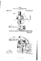
- Figure l is a side elevation, partly in section, of the needle-bar, throat-plate, presserfoot and related parts of a sewing machine, having that form of my attachment applied thereto which is adapted to trim the upper layers of fabric being sewed, Without trimming the lower layers;
- Figure l is a side elevation, partly in section, of the needle-bar, throat-plate, presserfoot and related parts of a sewing machine, having that form of my attachment applied thereto which is adapted to trim the upper layers of fabric being sewed, Without trimming the lower layers;
- Fig. 2 is a plan view of Fig. 1;
- Fig. 3 is a side elevation of Fig. 1; Fig.
- FIG. 4 is a plan view of the presser-foot and throat-plate
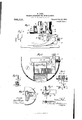
- Figs. 5 to 8 are views of that embodiment of my invent-ion in which all of the layers of the fabric that is being sewed are trimmed
- Fig. 5 being a plan view of the throat-plate with attached knife
- Fig. 6 being a front elevation, partly in section, of the entire attachment and related parts of the sewing machine
- Fig. 7 being a side elevation of the parts forming my attachment
- Fig. 8 being a vertical, sectional view of the knives
- Fig. 9 is a view of a series of upper knives having different degrees of offset.
- the object of my invention has been to provide a cutting attachment for sewing machines, which shall be adapted to permit cutting to be begun or discontinued at any point during the sewing, and which shall also if desired, enable the upper one of several layers of cloth to be out without injuring the cloth beneath; and to such ends my invent-ion consists in the trimming attachment for sewing machines hereinafter specified.
- I provide a frame that is adapted to be secured to the needlebar, such frame having a socket provided with a screw, by which it can be clamped on the needle bar.
- the frame A is provided with ears B, between which is pivoted a plate G, to which the knife D, is adapted to be secured.
- the pivot c, of the plate 0 carries a spring E, wound about such pivot, and
- a guard G is secured to the frame A, in such position that it surrounds and 5 protects the knife when the knife is in its inoperative position.
- the handle F may conveniently extend through a slot in the guard.
- a latch K is provided, the latch being conveniently mounted l in a socket L, secured to the guard.
- the latch preferably consists of a beveled head M, over whose bevel the plate C, is adapted to ride when passing to vertical position, the head having a stem extending through the socket, a spring K being coiled about the stem in the socket, tending to force the head toward the plate 0.
- the latch has a knob by which it may be retracted.
- the knife preferably consists of a plate d, and a slotted shank (Z connected by a neck d
- the knife D is adapted to out against a knife N, secured to a plate carried by an arm extending from a bar 0, the latter passing through a horizontal socket, formed in the presser foot, and being secured in adjusted position by a screw P.
- I provid' a series of knives I), having necks d of different lengths, so that the blade will stand in proper relation to the lower knife wherever that may be placed.
- the knife D rises out of contact with the knife N, at every stroke of the needle bar some special means is required that will enable these knives to press against each other during cutting, and yet that will prevent their breaking against each other as they come together.
- That form of my invention which is illustrated in Figs. 5 to 8 is intended for use where it is desired to cut entirely through all of the fabrics being sewed. It differs only in the following particulars: A removable throat plate P, is secured in the table of the machine, and a removable lower knife Q,
- the upper knife R preferably has the same shank and neck as the knife D, but on its lower edge it is provided with a finger r, on which the bevel T is formed, that co-acts with the bevel q, knife Q.
- the finger r helps the knife to enter the goods, and is especially useful with heavy goods.
- a workman desires to sew the edges of a hip pocket, and at the same time out the pocket-opening in the trousers, he places the goods under the machine, turns. the knife upward, and begins to sew. He may, if desired, begin 7 the seam some distance before he begins to cut. The knife remains down and the cutting continues until the pocket opening has been cut the desired length, when the knife is raised to inoperative position by means of ment for a sewing machine, member adapted to be secured .the handle, and the sewing can continue. Its abilityto begin cutting or stop cutting at any-desired point is a great advantage. 7 I realize that my invention is capable of embodiment in different forms and I desire not to be limited beyond the requirements of the prior art or the necessary intendinent of my claims.
- the herein-described trimming attachcomprising a to the needle bar, a support pivoted to said bar and adapted to be adjustably connected to said support and held in difierent positions, a blade adapted to be held parallelwith the needle,
- a trimming attachment for sewing machines comprising a holder adapted to be secured to the needle bar, a support hinged to said holder, a blade adjustably secured to said support, means for holding said support and said blade in a vertical position, and also at an angle lower part adapted to be table of the machine, adapted supported by the to be detachably secured in a vertical osition to said lower part.
- n edge trimming attachment for sewing machines comprising a holder adapted to be secured to the needle bar and provided with a hinged support, a blade adjustably secured to said support, meansfor holding said support and said blade in a vertical position and at an angle to said needle bar, and a vertically placed detachable lower blade.
- a knife pivoted to the needle bar, and adapted to be placed either in a vertical operating position, or in a horizontal inoperative position, and a guard carried by the needle bar and adapted to surround said knife when in the latter position.
- a member adaptedto be secured to the needle bar, a knife pivoted to said member, a fastening adapted to secure said and a lower bladeto the needle bar, a
- a trimming attachment for sewing machines, the combination of a knife adapted to be secured to the needle bar, and a lower knife with which said first-mentioned knife is adapted to cut, the cutting edges of said knives being oblique to each other to produce the usual shearing action, and one of said knives being beveled at the points where the knives first meet so that said 01 lique cutting edges are prevented from striking against each other but caused to pass each other.
- a trimming attachment for sewing machines, the combination of a knife adapted to be secured to the needle bar, a lower knife with which said first-mentioned knife is adapted to cut, the cutting edges of said knives being oblique to each other to produce the usual shearing action, and the meeting points of said knives being beveled or slightly inclined to the path of movement of the upper knife, so that said knives shall be prevented from striking each other and shall be caused to pass each other.
- a needle bar an upper knife adapted to be secured to the needle bar, a lower knife, a work support for the goods being sewn, and a presser foot for supporting said lower knife at a distance from said work support and from the bottom of the presser foot to leave an unobstructed space between the knife and work support and presser foot.
- I11 a trimming attachment for sewing machines, the combination of a knife adapted to be secured to the needle bar, said knife being immovable relative to the needle bar when cutting, a lower knife provided with means rendering it capable of lateral adjustment to and from the knife upon the needle bar, and a support carried by the presser foot for said lower knife.
- a trimming attachment for sewing machines, the combination of a member secured to the needle bar, a plate pivoted to said member, a series of knives, each of which is adapted to be secured to said plate. said knives having different degrees of offset, a support carried by the presser foot, and laterally adjustable thereon, and a lower knife carried by said support.
- a trimming attachment for sewing machines the combination of a plate adapted to be secured to the needle bar, a series of knives, each of which is adapted to be secured to said plate, said knives having different degrees of offset, and a laterally adjustable lower knife adapted to cooperate with said upper knife.
Landscapes
- Engineering & Computer Science (AREA)
- Textile Engineering (AREA)
- Sewing Machines And Sewing (AREA)
Description
W. KOHN.
TRIMMING ATTAGHMENT FOR SEWING MACHINES. APPLIGATION FILED 111111.29, 1907.
. 985,1 15. 1 Patented Feb.21, 1911.
2 BHEETSSHEET i.
WITNESSES fi/mWZ W m w. KOHN. TRIMMING ATTACHMENT FOR SEWING MACHINES.
APPLICATION FILED MAR. 29, 1907.
Patented Feb.21, 1911.
2 SHEETS-SHEET 2.
A TTOHNEY.
co., WASHINGTON, n. c.
IINITED STATES WILLIAM KOHN,
OF BROOKLYN, NEW YORK.
TRIIVIMIN G ATTACHMENT FOR SEWING-MACHINES.
aeaiis.
Specification of Letters Patent.
Patented Feb. 21, 1911.
Continuation of application Serial No. 312,319, filed April 18, 1906. This application filed March 29, 1907. Serial No. 365,394.
To all whom it may concern:
Be it known that I, WILLIAM KOHN, of Brooklyn, in the county of Kings, and in the State of New York, have invented a certain new and useful Improvement in Trimming Attachments for Sewing-Machines, and do hereby declare that the following is a full, clear, and exact description thereof, reference being had to the accompanying drawings, in which Figure l is a side elevation, partly in section, of the needle-bar, throat-plate, presserfoot and related parts of a sewing machine, having that form of my attachment applied thereto which is adapted to trim the upper layers of fabric being sewed, Without trimming the lower layers; Fig. 2 is a plan view of Fig. 1; Fig. 3 is a side elevation of Fig. 1; Fig. 4 is a plan view of the presser-foot and throat-plate; Figs. 5 to 8 are views of that embodiment of my invent-ion in which all of the layers of the fabric that is being sewed are trimmed, Fig. 5 being a plan view of the throat-plate with attached knife, Fig. 6 being a front elevation, partly in section, of the entire attachment and related parts of the sewing machine, Fig. 7 being a side elevation of the parts forming my attachment, and Fig. 8 being a vertical, sectional view of the knives; and Fig. 9 is a view of a series of upper knives having different degrees of offset.
The object of my invention has been to provide a cutting attachment for sewing machines, which shall be adapted to permit cutting to be begun or discontinued at any point during the sewing, and which shall also if desired, enable the upper one of several layers of cloth to be out without injuring the cloth beneath; and to such ends my invent-ion consists in the trimming attachment for sewing machines hereinafter specified.
In carrying my invention into practice, as illustrated in Figs. 1 to 4, I provide a frame that is adapted to be secured to the needlebar, such frame having a socket provided with a screw, by which it can be clamped on the needle bar. The frame A, is provided with ears B, between which is pivoted a plate G, to which the knife D, is adapted to be secured. The pivot c, of the plate 0, carries a spring E, wound about such pivot, and
bent around a handle F, extending from the side of the plate. The spring normally tends to hold the plate C, and with it the knife in an elevated position so that the knife will not out. A guard G, is secured to the frame A, in such position that it surrounds and 5 protects the knife when the knife is in its inoperative position. The handle F may conveniently extend through a slot in the guard. In order to hold the knife in vertical and operative position, a latch K, is provided, the latch being conveniently mounted l in a socket L, secured to the guard. The latch preferably consists of a beveled head M, over whose bevel the plate C, is adapted to ride when passing to vertical position, the head having a stem extending through the socket, a spring K being coiled about the stem in the socket, tending to force the head toward the plate 0. The latch has a knob by which it may be retracted. The knife preferably consists of a plate d, and a slotted shank (Z connected by a neck d The knife D, is adapted to out against a knife N, secured to a plate carried by an arm extending from a bar 0, the latter passing through a horizontal socket, formed in the presser foot, and being secured in adjusted position by a screw P. In order to enable cutting to be done at different distances from the needle, I provid' a series of knives I), having necks d of different lengths, so that the blade will stand in proper relation to the lower knife wherever that may be placed. As the knife D, rises out of contact with the knife N, at every stroke of the needle bar some special means is required that will enable these knives to press against each other during cutting, and yet that will prevent their breaking against each other as they come together. I form the cuttlng edge of the knife D, at an angle to the horizontal, and then bevel the lower point of the knife at (Z slightly, and form a corresponding bevel a, on the knife N. I am then enabled to adjust the knives so that they press firmly against each other during cutting, and yet when they come together after havlng been separated, they do not break because the bevel (Z rides laterally on the bevel a, and I thus guides the knives into proper relatlon. I regard this as a very important feature of my invention.
In the use of my attachment, as illustrated l in Figs. 1 to 4: for instance, in sewing a strap to the outside of a garment, or in sewlng the knife D, cuts the edge of garment, and beneath the edge of the strap to be sewed and trimmed. The machine 1s' then set in motion, and as the seam is formed, the strap at needle bar, and the length each stroke of the of its effective cutting stroke is so short that it does not pass below the bottom of the plate injure the lower fabric.
. on the lower carrying the knife N, and therefore does not It will cut on a curve as well as on a straight line.
That form of my invention which is illustrated in Figs. 5 to 8 is intended for use where it is desired to cut entirely through all of the fabrics being sewed. It differs only in the following particulars: A removable throat plate P, is secured in the table of the machine, and a removable lower knife Q,
is secured to the plate I The upper knife R, preferably has the same shank and neck as the knife D, but on its lower edge it is provided with a finger r, on which the bevel T is formed, that co-acts with the bevel q, knife Q. The finger r, helps the knife to enter the goods, and is especially useful with heavy goods.
In using that form of myinvention illustrated in Figs. 5 to 8 if, for instance, a workman desires to sew the edges of a hip pocket, and at the same time out the pocket-opening in the trousers, he places the goods under the machine, turns. the knife upward, and begins to sew. He may, if desired, begin 7 the seam some distance before he begins to cut. The knife remains down and the cutting continues until the pocket opening has been cut the desired length, when the knife is raised to inoperative position by means of ment for a sewing machine, member adapted to be secured .the handle, and the sewing can continue. Its abilityto begin cutting or stop cutting at any-desired point is a great advantage. 7 I realize that my invention is capable of embodiment in different forms and I desire not to be limited beyond the requirements of the prior art or the necessary intendinent of my claims.
'This application is a continuation of my application No. 312,319, filed April 18th, 1906, this present application containing the invention of the earlier application, with certain improvements, cation having been abandoned in favor of the present application.
1. The herein-described trimming attachcomprising a to the needle bar, a support pivoted to said bar and adapted to be adjustably connected to said support and held in difierent positions, a blade adapted to be held parallelwith the needle,
previously I on top of the I and the earlier applitically adjustable blade adapted to be held in a vertical position parallel with said needle bar, means for holding said blade in different positions, a
lower part adapted to be supported b T the table of the machine, and a second blade secured to said lower part at a predetermined distance from the needle and with which the first-named blade cooperates, said last-named blade having a cutting edge formed by the meeting ofuppcr and side faces inclined to the path of movement of the first-named blade.
3. A trimming attachment for sewing machines, comprising a holder adapted to be secured to the needle bar, a support hinged to said holder, a blade adjustably secured to said support, means for holding said support and said blade in a vertical position, and also at an angle lower part adapted to be table of the machine, adapted supported by the to be detachably secured in a vertical osition to said lower part.
4. n edge trimming attachment for sewing machines, comprising a holder adapted to be secured to the needle bar and provided with a hinged support, a blade adjustably secured to said support, meansfor holding said support and said blade in a vertical position and at an angle to said needle bar, and a vertically placed detachable lower blade. v
5. In a trimming attachment for sewing machines, the combination of a knife pivoted to the needle bar, and adapted to be placed either in a vertical operating position, or in a horizontal inoperative position, and a guard carried by the needle bar and adapted to surround said knife when in the latter position.
6. In a trimming attachment for sewin machines, a member adaptedto be secured to the needle bar, a knife pivoted to said member, a fastening adapted to secure said and a lower bladeto the needle bar, a
tending to hold said knife in a horizontal position, and a guard surrounding said knife when in its horizontal position.
8. In a trimming attachment for sewing machines, the combination of a knife adapted to be secured to the needle bar, and a lower knife with which said first-mentioned knife is adapted to cut, the cutting edges of said knives being oblique to each other to produce the usual shearing action, and one of said knives being beveled at the points where the knives first meet so that said 01 lique cutting edges are prevented from striking against each other but caused to pass each other.
9. In a trimming attachment for sewing machines, the combination of a knife adapted to be secured to the needle bar, a lower knife with which said first-mentioned knife is adapted to cut, the cutting edges of said knives being oblique to each other to produce the usual shearing action, and the meeting points of said knives being beveled or slightly inclined to the path of movement of the upper knife, so that said knives shall be prevented from striking each other and shall be caused to pass each other.
10. In a sewing machine, the combination of a needle bar, an upper knife adapted to be secured to the needle bar, a lower knife, a work support for the goods being sewn, and a presser foot for supporting said lower knife at a distance from said work support and from the bottom of the presser foot to leave an unobstructed space between the knife and work support and presser foot.
11. In a sewing machine, the combination of a needle bar, an upper knife pivoted to the needle bar, a lower knife, a work support and a presser foot for supporting said lower knife at a distance from said work support and from the bottom of the presser foot to leave an unobstructed space between lfzhe knife and work support and presser oot.
12. I11 a trimming attachment for sewing machines, the combination of a knife adapted to be secured to the needle bar, said knife being immovable relative to the needle bar when cutting, a lower knife provided with means rendering it capable of lateral adjustment to and from the knife upon the needle bar, and a support carried by the presser foot for said lower knife.
13. In a trimming attachment for sewing machines, the combination of an upper knife pivoted to the needle bar, said knife being immovable relative to the needle bar when cutting, and a lower knife rigidly carried by the presser foot, and provided with means rendering it capable of lateral adjustment to and from the knife upon the needle bar.
14. In a trimming attachment for sewing machines, the combination of a member secured to the needle bar, a plate pivoted to said member, a series of knives, each of which is adapted to be secured to said plate. said knives having different degrees of offset, a support carried by the presser foot, and laterally adjustable thereon, and a lower knife carried by said support.
15. In a trimming attachment for sewing machines, the combination of a plate adapted to be secured to the needle bar, a series of knives, each of which is adapted to be secured to said plate, said knives having different degrees of offset, and a laterally adjustable lower knife adapted to cooperate with said upper knife.
In testimony that I claim the I have hereunto set my hand.
WILLIAM KOI-IN.
foregoin Witnesses:
EDWIN J. PRINDLE, LILLIE Cass.
Priority Applications (1)
| Application Number | Priority Date | Filing Date | Title |
|---|---|---|---|
| US36539407A US985115A (en) | 1907-03-29 | 1907-03-29 | Trimming attachment for sewing-machines. |
Applications Claiming Priority (1)
| Application Number | Priority Date | Filing Date | Title |
|---|---|---|---|
| US36539407A US985115A (en) | 1907-03-29 | 1907-03-29 | Trimming attachment for sewing-machines. |
Publications (1)
| Publication Number | Publication Date |
|---|---|
| US985115A true US985115A (en) | 1911-02-21 |
Family
ID=3053459
Family Applications (1)
| Application Number | Title | Priority Date | Filing Date |
|---|---|---|---|
| US36539407A Expired - Lifetime US985115A (en) | 1907-03-29 | 1907-03-29 | Trimming attachment for sewing-machines. |
Country Status (1)
| Country | Link |
|---|---|
| US (1) | US985115A (en) |
Cited By (4)
| Publication number | Priority date | Publication date | Assignee | Title |
|---|---|---|---|---|
| US2510929A (en) * | 1946-04-02 | 1950-06-06 | Helen S Ketcham | Shearing attachment for sewing machines |
| US2617374A (en) * | 1951-01-25 | 1952-11-11 | Robertis Nicola De | Combined sewing machine and trimmer blade |
| US2982242A (en) * | 1957-02-06 | 1961-05-02 | Wolf Oscar | Sewing method and apparatus and article made thereby |
| US3171372A (en) * | 1963-01-29 | 1965-03-02 | Union Special Machine Co | Edge trimming mechanism for sewing machines |
-
1907
- 1907-03-29 US US36539407A patent/US985115A/en not_active Expired - Lifetime
Cited By (4)
| Publication number | Priority date | Publication date | Assignee | Title |
|---|---|---|---|---|
| US2510929A (en) * | 1946-04-02 | 1950-06-06 | Helen S Ketcham | Shearing attachment for sewing machines |
| US2617374A (en) * | 1951-01-25 | 1952-11-11 | Robertis Nicola De | Combined sewing machine and trimmer blade |
| US2982242A (en) * | 1957-02-06 | 1961-05-02 | Wolf Oscar | Sewing method and apparatus and article made thereby |
| US3171372A (en) * | 1963-01-29 | 1965-03-02 | Union Special Machine Co | Edge trimming mechanism for sewing machines |
Similar Documents
| Publication | Publication Date | Title |
|---|---|---|
| US985115A (en) | Trimming attachment for sewing-machines. | |
| US4008672A (en) | Work guiding and trimming apparatus for sewing machines | |
| US1065941A (en) | Strip-cutting attachment for sewing-machines. | |
| US2165313A (en) | Trimming mechanism | |
| US1010830A (en) | Thread-cutting atttachment for sewing-machines. | |
| US2475759A (en) | Sewing machine and attachment therefor | |
| US472094A (en) | Island | |
| US1136846A (en) | Trimming mechanism for sewing-machines. | |
| US390109A (en) | willoox | |
| US1403807A (en) | Trimming mechanism for sewing machines | |
| US255336A (en) | Inson | |
| US954553A (en) | Trimming mechanism for sewing-machines. | |
| US1928587A (en) | Trimming mechanism for sewing machines | |
| US849347A (en) | Seam-trimmer and edge-binder for sewing-machines. | |
| US1048204A (en) | Trimming device for sewing-machines. | |
| US704200A (en) | Sewing-machine guide. | |
| US664977A (en) | Ripping attachment for sewing-machines. | |
| US771434A (en) | Thread holder and cutter for sewing-machines. | |
| US1097040A (en) | Trimming device for sewing-machines. | |
| US255578A (en) | And charles | |
| US273936A (en) | Trimming attachment for sewing-machines | |
| US454010A (en) | Trimming mechanism for sewing-machines | |
| US1727807A (en) | Cutter knife for hemstitching machines | |
| US630209A (en) | Sewing-machine trimmer. | |
| US381537A (en) | Trimming attachment for sewing-machines |