US984278A - Condenser. - Google Patents
Condenser. Download PDFInfo
- Publication number
- US984278A US984278A US3?514207A US984278DA US984278A US 984278 A US984278 A US 984278A US 984278D A US984278D A US 984278DA US 984278 A US984278 A US 984278A
- Authority
- US
- United States
- Prior art keywords
- liquid
- chamber
- inlet
- outlet
- fluid
- Prior art date
- Legal status (The legal status is an assumption and is not a legal conclusion. Google has not performed a legal analysis and makes no representation as to the accuracy of the status listed.)
- Expired - Lifetime
Links
- 239000007788 liquid Substances 0.000 description 70
- 239000012530 fluid Substances 0.000 description 29
- XLYOFNOQVPJJNP-UHFFFAOYSA-N water Substances O XLYOFNOQVPJJNP-UHFFFAOYSA-N 0.000 description 8
- 230000001131 transforming effect Effects 0.000 description 4
- 101100007970 Mus musculus Ctdspl gene Proteins 0.000 description 2
- 230000015572 biosynthetic process Effects 0.000 description 2
- 241001556567 Acanthamoeba polyphaga mimivirus Species 0.000 description 1
- 241000487076 Alosa fallax Species 0.000 description 1
- WJOHZNCJWYWUJD-IUGZLZTKSA-N Fluocinonide Chemical compound C1([C@@H](F)C2)=CC(=O)C=C[C@]1(C)[C@]1(F)[C@@H]2[C@@H]2C[C@H]3OC(C)(C)O[C@@]3(C(=O)COC(=O)C)[C@@]2(C)C[C@@H]1O WJOHZNCJWYWUJD-IUGZLZTKSA-N 0.000 description 1
- 101100128278 Mus musculus Lins1 gene Proteins 0.000 description 1
- 241000044800 Pellenes Species 0.000 description 1
- 241000104952 Xanthophyllum eurhynchum Species 0.000 description 1
- 238000005266 casting Methods 0.000 description 1
- 239000003795 chemical substances by application Substances 0.000 description 1
- 230000007423 decrease Effects 0.000 description 1
- AAOVKJBEBIDNHE-UHFFFAOYSA-N diazepam Chemical compound N=1CC(=O)N(C)C2=CC=C(Cl)C=C2C=1C1=CC=CC=C1 AAOVKJBEBIDNHE-UHFFFAOYSA-N 0.000 description 1
- VKYKSIONXSXAKP-UHFFFAOYSA-N hexamethylenetetramine Chemical compound C1N(C2)CN3CN1CN2C3 VKYKSIONXSXAKP-UHFFFAOYSA-N 0.000 description 1
- 150000002500 ions Chemical class 0.000 description 1
- 238000005192 partition Methods 0.000 description 1
- 238000005086 pumping Methods 0.000 description 1
- VWDWKYIASSYTQR-UHFFFAOYSA-N sodium nitrate Chemical compound [Na+].[O-][N+]([O-])=O VWDWKYIASSYTQR-UHFFFAOYSA-N 0.000 description 1
- 229940052996 vanos Drugs 0.000 description 1
Images
Classifications
-
- F—MECHANICAL ENGINEERING; LIGHTING; HEATING; WEAPONS; BLASTING
- F04—POSITIVE - DISPLACEMENT MACHINES FOR LIQUIDS; PUMPS FOR LIQUIDS OR ELASTIC FLUIDS
- F04D—NON-POSITIVE-DISPLACEMENT PUMPS
- F04D17/00—Radial-flow pumps, e.g. centrifugal pumps; Helico-centrifugal pumps
- F04D17/08—Centrifugal pumps
- F04D17/18—Centrifugal pumps characterised by use of centrifugal force of liquids entrained in pumps
Definitions
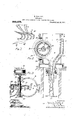
- Figure. l is n, diaglaininni@ iiinsti'aiimi in which :i porion of #im ring (if simios off the ar Shown in s@ liion, in cnn! nection .Wiih afsecionai Vid-ii' of :i distributin- 01 liquid ddii-rely mozzi@ angl foljce diag-ruins, 'which epreseni; the .ifeiociies of die liquid. cniering and .ie/giving th@ iinpeiier.
- il is a veriicnl section taken; tinough n cudenser embodying my invsitimi und Fig. 3 a View in cross Seciionaken iimgig he broken iin@ 3--3 of the .
- a de'vice such us n reciprocating anginet a.
- the walls ofvthe body portion near the bottom converge to form a collecting chiamber or combiningtube l() which decreases in cross sectional area from itsinlet ll to its outlet l2.
- A'castiig 13 (by means of bolts let, is secured to the bodyportion and has a diffuser l5 formed therein.
- the Walls 16 of the diffuser diverge so that its outlet 17 is larger than its inlet 18, which inlet is arranged axially Ain line with the collecting chamber 10.
- Casting 13 is of such shape that a chamber 19 is rovided whichV sur rounds and connects with the outlet of the collecting chamber and the inlet of the diffuser. y Chamber l?
- a cover cast, in two sections 23 and 24 bolted together atQ is secured to the body portion by means of bolts 26.
- Section 24 ot' the co'ver is cored so 'as to providey a water chamber 32 having an inlet -l adaptedto be connected. to a suitable source ot' supply of condensing' water.
- the chamber 32 has a tubular all 34 which snrrounds thc hnbof the impeller and also has im outlet 3.7 provided with partition. vanos 3l?. "lhc chamber 212 and th@l outlet 2. which laltcr may lic tei-mcd o now/.lc lic within the ring described bythe blalcs l
- the shaft is adapted to be rotatedat thev The faces 37 of the shroudsor ends of.
- vstream comprising the succession of separate leaves or filmsof liquid discharged from the rotating impeller ⁇ travels downwardly through the chamber 9 and is received by the collecting chamber 10, Where it. is compressed and' rendered more' compact and from which it is dischar ed, due to its initial velocity, into the d1 user or transformer The velocity ci the liquid is converted into pressure as theliquid.
- the films or leaves or' water discharged from the impeller blades operate as a series of separate pistons' l inv traversing the chamber 9 and the tube l() and thev .irremoved from the chamber 9 is conti ed between adjacent films or leaves and fis ejected from the condensing chamber the Water.
- an impeller provided with an annular roiv of blades, means for delivering liquid'to a number thereof, a. chamber rovideol with an inlet for fluid to be acte( upon by the discharged liquid and adapted to serve as a collectingand combining chamber, a' diffuser in line with the outlet of said chamber and a chamber surrounding the outlet of said first mentioned chamber and the inlet to said diffuser.
- an impeller provided with an annular row of. blades, uieanst'or delivering liquid to a number oi said blades less than the total number thereof.
- adevice oi'hthe character dcscri-iied ⁇ a bladed.inipellein means tor rotating said iiiipeller, means for deliveringr liquid to a number ot the blades thereof less than ther total iiuii'iber.
- a chamber provided with 'an inlet for the fluid Vto be acted upon b v the liquid discharged from said impeller and adapted to collectl and combine said liquid and said fluid and-a diffuser in comiiiuii-ication with the outlet of' said chamber.
- a bladed iiiipeller means for rotatiiigif said impellei, means for delivering liquid to a number of the blades thereof less than the total number, a' chamber provided With aii inlet for the fluid' to be acted upon -by the liquid discharged troni sa d impellcr and adapted to collect and conibinesaid liquid and said liuid and a difl'utcr in line with said chamber.
- liquid inlet aud an -outlet for coineatingy wiili said outlet.
- a bladcd ii'npollci adapted to discharge liquid through said f liquid i-iilct and iiicaiis 'lor delivering: liquid to a number of the blades of said impeller less than the total number thereof.
- the combination ot a collecting and combining chamber provided With :1 -fluid inlet, a liquid inlet and an outlet. for combining fluid and liquid, a diffuser conimimr eating with said inlet, an impellei: provided with an annular row of blades adapted to discharge liquid. through said liquid inlet and a nozzle located within the ring,Y devscribed by said blades for deliveriguer liquid thereto.-
- ⁇ a bladed rotatable iii'ipcllei. means for dcliver-ing' liquid to a portion of the pcriphery'thereof. a collector for the liquid projected by said iiiipeller. the longitudinal axis ot which is tangent to said inipeller and means for traiisforniinc'- the velocityv ot' said liquid iiito pressure.
- a chaii'ibercd iiieinliei proviiled with a fluid inlet. a liquid inlet and a combined liquid and tluid outlet.
- iiicai is adapted to receive thc liquid and fiuid delivered through said outlet and to transform thc ii'clocit/ v thereof into pressure and iiicans euiployiiw a bladcd l rotor clement for iro'ectinsi lit uid into said chaiiibered member through said liquid inlet'. 22%.
- ln a device of the character described'.
- a rotatable impcller provided with an ali-- iiiilar row 'ot blades, means for delivering! liquid to said inipeller iii .sucb'a manner that. it will be projected by said iiiipellct through ii portion only1 of its pei'ii'ibciy.
- a chamber into which said liquid is adapted to be projected provided with an inlet for the fluid to bc'acted upon by said liquid and an outlet ior said liquid and the fluid acted upon and means Ain connection with said outlet adapt,- ed to ti'aiisfi'oiin fluid velocity into pressure.
- a chambcicd iiieiiibei' provided with a. tluid inlet adapted to be connected to the device ⁇ trom which elastiertluid is to be i'iuniped, an outlet. an i4.000t.
- a bladcd rotatable impeller adapted to 'project liquid into the chiiiilicr o'l' said 'iiieinbcr aiiil toward vsaid member provided with e, Fluid inle; :iclaplefl outlet, Ineens for cleliverneg iquifl te seid inipeiler and 'means les sculptureiisferning he veleciiy of the "liquid paseing through Park endet im@ pressure k 25.
- Velocity iure sairl chamber between the inlet and entlet thereei, and :i passage arranged se :is i0 maintain a pressure :it Jche inlet to memorize veleeiiyirlinsforinine; means substantially 'the ⁇ seine iis the pressure within seid chember.
- means employing a partial eillux rotatable liquid impeller arranged so as to project liquid at a relatively high velocity in a suhdivided state into said chamber between the inlet and outlet thereof, means communieating with said outlet for transforming earners ⁇ succession of liquid lilms ot relatively high velocity into said chamber between the inlet and outlet thereoi"7 and ai passage arranged so as to maintain a pressure at the inlet to said velocity-transforn'iind means substantially the saine as the pressure within said chamber.
Landscapes
- Engineering & Computer Science (AREA)
- Mechanical Engineering (AREA)
- General Engineering & Computer Science (AREA)
- External Artificial Organs (AREA)
Description
M. LEBLANC.
GUNDENSER. Y :'APPLIOATION FILED MAB.. 22, 1905. EENBWED JULY 23, 190?. 984,278.,
Patented Feb. 14,1911.
have invented u new 30 moving Huid imm mv binde@ iin-palier 4iiiiizifiiii MAURECE LEBLANC. OF`PARLS, FRANCE,
Applicaton filed Marsch 22. i905,
l'b :LLL whom it 71mg/ corwein:
Be itviinnwn that iQlBiQaURic-n LEBLANC, citizen of in@ Repnbiic* mi' iiiiain-u, rfi/:Ming zii Yiiia Mmmmowing', Liinnil, Pm". Fininfo.
ri mein! {mpi-ovef nini' in Condominium, ni which ihn tfiilmving l' u speciication.
@uint A11 object 0i ihi's im'animi to lifnffinfu o1' provide a snilpi@ imi eiiivien iiuifi immian'ing device iur-apparatus fuif'inechnnicai forming u stream @,i jet (ff liquid (if 'nigh Veociy. Y
A mihe objec" in piodnc@ 01' p @vde a dev-.ice or apuam-ns foi' mecha .smily forming :i stream' or jet of liquid of high' Velocity subdivided wat it has th@ power 11o entrain una Cari-5f with ii' from une point i0 n point nf. graaienpi'esSm-Q moie- Qinstic ilnid fui a given immuni" if iiqnid :it a giwii veiociiy than can 'me Carin/Xd by my mi ilu" iiquiri jet yfievices in iis@ beoe my :nvnuiinn so far :is know.l y A Stili further Oblixct La in produce 'mi g provide an eiicicit v` V' 130i' milixg ing my vnovel iiquid jet-hymn 5mn? camjying away ihe coudensd anni non-cm- {ioninble inpnls u Well M foi'- p91' iizii1f die uct ofvcondensing ille cnndvnszibiv Nimh.
Figure. l is n, diaglaininni@ iiinsti'aiimi in which :i porion of #im ring (if simios off the ar Shown in s@ liion, in cnn! nection .Wiih afsecionai Vid-ii' of :i distributin- 01 liquid ddii-rely mozzi@ angl foljce diag-ruins, 'which epreseni; the .ifeiociies of die liquid. cniering and .ie/giving th@ iinpeiier. il is a veriicnl section taken; tinough n cudenser embodying my invsitimi und Fig. 3 a View in cross Seciionaken iimgig he broken iin@ 3--3 of the .The uidvranslaing device @onsiss of: isti. A lbizided, remt-abi@ 1impeiiei'; distril'niter 'for delivering iqnidE Such as water, to a number of blades 0f ihe'jir palier less`than the total lnunber; 3rd. A de'vice, such us n reciprocating anginet a. steam 01h water turbine or an ieleciric motor.,l o driving or iotaiingthe impeliei; 4th. A collecting chaniber 01 combll'xng 'tube :for colicing the iquid piog'ccted by the impeliex: und compnet-ing Jr-reducing the cross his iin/i Spawe.
section thefeof Without increasing iis primf e-ipiain 'the im' n of my di. mimi Fig.
which xviii Spd'o: *iin4 spout 3 is u ring' disci-iii n'ain `mi like hmies i 'Ti/iat iio infiiliiiitcr delivers .iiqi
COU"
` mis upon :Lila fm A vxfew w as :i C@ An amount m, :MMM eine 4;@ ihn @fenix gui pumping action he blades nas a, in ze i055 ivi eiciencf". 'but "n my' device ai! mp5 die nis: -nzwz' uihc iqizii leaving the imw 'peiiei is e'i'eciieiy fuiiilzed. This is of the utmost iniporance when vtieains or 'jets of iiquid of 'nigh ifeiooi'y im? necQSsm-y.
in ih@ fingjvit'honi; miyifiea of limiilngj fue invaiion, 'but nniy 'with 1 e idea of slmvi one svagizaiifin, hzweiilnsimted Eil duit for .conducting to it the xsteam to be condensed. I
The walls ofvthe body portion near the bottom converge to form a collecting chiamber or combiningtube l() which decreases in cross sectional area from itsinlet ll to its outlet l2. A'castiig 13,(by means of bolts let, is secured to the bodyportion and has a diffuser l5 formed therein. The Walls 16 of the diffuser diverge so that its outlet 17 is larger than its inlet 18, which inlet is arranged axially Ain line with the collecting chamber 10. Casting 13 is of such shape that a chamber 19 is rovided whichV sur rounds and connects with the outlet of the collecting chamber and the inlet of the diffuser. y Chamber l? is connected to the condensing chamber by `sans of a passage 20 cored in the bodl 'l j ion. andf'vhich terminates at one end "in a por, 2l leading into themendensinf"chamber and at the other end in a recess @which forms a portion of chamber 19. The passage 20 operates as an equalizing passitge and insures the same pressure in the chamber .19 as that existing in the chamber 9. Avv 1th this arrangement' the stream of liquid ejected from the outlet'12 does not have to overcome an. increase of pressure in entering thechamber 19.
' A cover cast, in two sections 23 and 24 bolted together atQ is secured to the body portion by means of bolts 26.
An' ihipeller 2T carrying an annular row of blades (28 'is mounted onshaft 29 joue' naledhin. bearings B0 which are located between the bodv portion 8 and the cover forned by sections 23 and 24. desired speed by means .of an electric motor 31. which, of course, 1f`des1red,may be replaced by any other type ol motor, such as a steam or Water turbine or a reciprocatinfr engine., l
the .bladesdiverge; therefore, the Water projected by the blades 4will be in. the nature of.. lil1ns or leaves of fan-like formation and at the velocity imparted .to them will be projected toward the collecting chamber. In this Way a minute subdivision of thewater is attained `and it has been found that the' capacity of such a stream or jet for condensing stcam'or vapor andfor removing air or other non-condensable frases and uncondensed vapor, is extremely liigh.-
rThe operationof the device s as 'follows'.
rThe vstream comprising the succession of separate leaves or filmsof liquid discharged from the rotating impeller` travels downwardly through the chamber 9 and is received by the collecting chamber 10, Where it. is compressed and' rendered more' compact and from which it is dischar ed, due to its initial velocity, into the d1 user or transformer The velocity ci the liquid is converted into pressure as theliquid.
traverses the diffuser. The films or leaves or' water discharged from the impeller blades operate as a series of separate pistons' l inv traversing the chamber 9 and the tube l() and thev .irremoved from the chamber 9 is conti ed between adjacent films or leaves and fis ejected from the condensing chamber the Water.
I have found by experience that itias` de- I,
` srable to; have the separate leaves, orthe .stream composedof the separate leaves, projected from'the impeller into the con- (lensing` chamber, at a point between the admission port, through which air enters the chamber, and the discharge )ort from which the air is ejected.` In a dition to this. I find it desirable tlconfine the leaves or -`1lms of liquid by 'means of the walls of the tube ortubular passais through which they more -in order to o tain the highest efficiency. By providing such a tube or passage, thc analogy between the operation olfv cach leaf, traversing the passage, and a,y piston will bc more marked.' My theory is, that the leal', at the time 'ot' its formation and lsubset]uently', must bc subjected to substantially equal pressures on both sides, or else it will break into a muss of separato drops :md be renderedv loss cficctivc as a lluifl translating agent.A
As the separate",leaves travel down- Anumber ofsaid blades less than the total 'discharge liquid into said chamber and total number thereof.
'bined fluid and liquid. a difl'user commuiii collecting and combining chamber and a diffuser in line with the outlet of said chainber.
1Q. In a device of the character described, an impeller provided with an annular roiv of blades, means for delivering liquid'to a number thereof, a. chamber rovideol with an inlet for fluid to be acte( upon by the discharged liquid and adapted to serve as a collectingand combining chamber, a' diffuser in line with the outlet of said chamber and a chamber surrounding the outlet of said first mentioned chamber and the inlet to said diffuser.
13. In a device of the character described, an impeller provided with an annular row of. blades, uieanst'or delivering liquid to a number oi said blades less than the total number thereof. a chamber rorided `with an inlet for fluid to be acte upon by the discharged liquid and adapted to serve as a collecting and combining chamber, ar diffuser in line with the out-let of said chamber, a eliaiiibei surrounding the outlet ot said first mentioned chamber and the inletI to. said ditliiser'and 'means other than the outlet to said first mentioned chamber. for` placing said two chambers iii communication one with the other.
ll. .ln adevice oi'hthe character dcscri-iied` a bladed.inipellein means tor rotating said iiiipeller, means for deliveringr liquid to a number ot the blades thereof less than ther total iiuii'iber. a chamber provided with 'an inlet for the fluid Vto be acted upon b v the liquid discharged from said impeller and adapted to collectl and combine said liquid and said fluid and-a diffuser in comiiiuii-ication with the outlet of' said chamber.
l5. In a device ol the character. described. a bladed iiiipeller. means for rotatiiigif said impellei, means for delivering liquid to a number of the blades thereof less than the total number, a' chamber provided With aii inlet for the fluid' to be acted upon -by the liquid discharged troni sa d impellcr and adapted to collect and conibinesaid liquid and said liuid and a difl'utcr in line with said chamber. I
'16. The coiiibinationfof lincollcctiiig` and coii'ibining chamber. :i diffuser eoiiiiiiunicat-` ing' tluirewitli, a bladcd imileller adapted to nicaiis l'oi'mdelivering liquid to :i number of the blades o'lE lsaid iiiipcllei' less than `thi` li'. 'lhe coi'iibiiiatioii ot a collecting and i-oii'ibiiiiiig' chamber provided with a fluid inlet. a. liquid inlet aud an -outlet for coineatingy wiili said outlet. a bladcd ii'npollci adapted to discharge liquid through said f liquid i-iilct and iiicaiis 'lor delivering: liquid to a number of the blades of said impeller less than the total number thereof.
18. The combination. of a collect combining chamber provided With u.; inlet, a liquid inlet and an outlet for combilled, fluid and liquid, a diffuser communieating with said outlet. u bladed impeller adapted to 4discharge liquid through said liquid inlet and means for delivering liquid to said impeller.A
19. The combination ot a collecting and combining chamber provided With :1 -fluid inlet, a liquid inlet and an outlet. for combining fluid and liquid, a diffuser conimimr eating with said inlet, an impellei: provided with an annular row of blades adapted to discharge liquid. through said liquid inlet and a nozzle located within the ring,Y devscribed by said blades for deliveriguer liquid thereto.-
20. In a device oi the. character described.
`\a bladed rotatable iii'ipcllei. means for dcliver-ing' liquid to a portion of the pcriphery'thereof. a collector for the liquid projected by said iiiipeller. the longitudinal axis ot which is tangent to said inipeller and means for traiisforniinc'- the velocityv ot' said liquid iiito pressure.
21. ln ii device of the character described.- a bladed rotatable iiiipellerl-iiicaiis toi' dciiveiiiigiliquid thereto. a collector toi' tbc liquid projected b v said impcllci'. the loiigiitiidiiial axis ot which is tangenti to said ini pellei' and uicaiis for'transforming the relocity ot said liquid into i'iicssiire.
:'22. lu a device ot' the character described. a chaii'ibercd iiieinliei: proviiled with a fluid inlet. a liquid inlet and a combined liquid and tluid outlet. iiicaiis adapted to receive thc liquid and fiuid delivered through said outlet and to transform thc ii'clocit/ v thereof into pressure and iiicans euiployiiw a bladcd l rotor clement for iro'ectinsi lit uid into said chaiiibered member through said liquid inlet'. 22%. ln a device of the character described'.
a rotatable impcller provided with an ali-- iiiilar row 'ot blades, means for delivering! liquid to said inipeller iii .sucb'a manner that. it will be projected by said iiiipellct through ii portion only1 of its pei'ii'ibciy. a chamber into which said liquid is adapted to be projected provided with an inlet for the fluid to bc'acted upon by said liquid and an outlet ior said liquid and the fluid acted upon and means Ain connection with said outlet adapt,- ed to ti'aiisfi'oiin fluid velocity into pressure.
In an elastic tluid puiiip, a chambcicd iiieiiibei' provided with a. tluid inlet adapted to be connected to the device `trom which elastiertluid is to be i'iuniped, an outlet. an iiilet. for liquid located between said fluid iiilet and Isaid outlet, a bladcd rotatable impeller adapted to 'project liquid into the chiiiiilicr o'l' said 'iiieinbcr aiiil toward vsaid member provided with e, Fluid inle; :iclaplefl outlet, Ineens for cleliverneg iquifl te seid inipeiler and 'means les iriiiisferning he veleciiy of the "liquid paseing through Sinai endet im@ pressure k 25. ln en elesiie 'lnui pump, ii 'chembereel o lie @mimi-tiem@ ice the device :frein which elesic liuicl le to he pumped, en eule'r, an 1nlet for hemd leeeerl between seid fluid in ef' the fflniil pessime pellen edilpeell-e preieciliquid info the chamber of said member anillewercl seul outlet. meirisiur reliiering liquiil le seid iinpeller and nieaiisvi'er raising' ille pressure threugh snifl outlet above the pressure exisl'ing .in seid eliernber.
2G. ln eeinhinatien willi e einiinl'ier provided with an inlet` ei fluid enel eem/'ergiu au outlet. ineens ing walls terminer' ih" ernpleyii'ig i: rotatable liquid impeller for tilting euicl inipeiler.
delivering liquirl in vided with an inlet'. 'for fluid and eeniferging Walls terminiitii12g in in ouisle? means erranged :is ro ir-Dieci; liquid ai :i reliiively high Velocity in the erm of hlm@ er leaves flo finte said chamber lweiiiieen the in l. uml ouf,-
walls terminating in eid 1,11-
let thereof nifl ineens ier reti-iin peller. i 29. ln winhinziliun i li e {clin-:liber pre! vided willi in inici; ui' uuid sind converging enle:E fr partiel elilux impeller 'eil se es uid ai; e relatively high vele@ Y el lins er leaves inl() L'nifl elixnl, ,i the-inlet und outlet {herr-Lof.
'h'l. in cernhinulimi willi. u Plminlier previdecl with :in inlet lier fluid and Converging wells leiininnling' in un uulehnieeiie;ein- ]lhpying :L pnrtiul elfi-ux reir-.hilfe liquid iinpeller :1r iing-eil se :is in proie@ uid et rel.-
:nively high velocity in i subuiiiilerl sleuf inte :mid elunneei' heine-en 'llie inlet "eule lhei'eoi' anni ineens eeininuiiiefiling 'with seid nullil 'hir lriine'eiininf iuici ve lmtity lille pr h 3l. Yln coin vided with 'en wells t-erininalizig in en eulel.,.ineeiis ceininunieetiifig Wi'sh farmed lriixisfermirig fluid ,feleeiij? inea pressure i,
ineens ei'iipleynig i partial ei'iux liquid und outlet thereof.
23,3. In eeinhinzifion with a chamber 1ere* vided willi an inlet for Huid und converging walls terminiiiing :in iin outlet, means einpleyin partiel elilnx rotatable liquid inigeiler winged se es to proJeet liquid et zi relatively, high velocity in sul'iclivirleel Stute iiiio said uhsn'iher between the inlet und eutleb i'heijefiiz, ineens eominuiiiceling Willi snicl eulet fer rzinsforuiiug lluifl velocity inte ausl e passage arranged solis te inziinleiii is, gneseure et the inlet to seid veloeily rr, Forming means substantially the suine the pressure Within said chamber.
ll. in een'ihiniiieii wih ii Chamber pre .l willi i -let iier fluid and. converging falls terminating in :in outlet, inea-ns eemn munlcziingr wii'h said outlet ernied for transferi'ning liujjl velocity into pressure, means einple'vifinghzi parcial eillux liquidv iin peller urruriged se as lie project e. succession of liquid films el? relatively high Velocity iure sairl chamber between the inlet and entlet thereei, and :i passage arranged se :is i0 maintain a pressure :it Jche inlet to seul veleeiiyirlinsforinine; means substantially 'the `seine iis the pressure within seid chember.
ii eeniliination 'with i clieinlieiprovcled with im inlet for 'iuifl inkl eonverging wells ie :iii oit-flee, ineens couiniuniezilfJ i .will enfle@ fer transforme ing fluid veler: d inte iiressiuej eur. f partiel ejeelion ieiilnhle liquid erung-ed se :is le project liquid iii lie .ifnni of L pressure :it the inlet te z y :nung ineens sunshinne :is the pressure within sami i 'ni'iliinetieii uiiizli :i eheuiber pre miei, 'for luicl :mel en eutlel,
mee to project liquid :it e nigh velue/ily iii #he ferm 0i' leaves inte sind chamber between mil men ns for S. eemliinarien with e. chamber pro- Vlleu *li in inlet for fluid end :in out/le, e partei impeller erreigigefl se lo liujjiill et e relatively high ifelmily ef :nul :i passage arranged in the form of tilms or leaves into said chamber between 'the inlet and outlet thereof.
38. In combination witha chamber provided 'with an inlet for fluid and an outlet, means employing a partial efilux 'rotatable liquid impeller arranged so 4as to project liquid at relatively high velocity in a sub? divided state into said chambeijbetween the inlet and outlet thereof and means commuicating With said outlet for transforming `transforining` fluid velocity into pressure and means einployin a partial' ejection roi tatable liquid impel er arranged so as to project liquid at relatively high velocity in the form of films into said chamber between inlet and outlet thereof. y
4l'. In combination with a chamber provided vvith van inlet for fluid and an outlet,
means employing a partial eillux rotatable liquid impeller arranged so as to project liquid at a relatively high velocity in a suhdivided state into said chamber between the inlet and outlet thereof, means communieating with said outlet for transforming earners `succession of liquid lilms ot relatively high velocity into said chamber between the inlet and outlet thereoi"7 and ai passage arranged so as to maintain a pressure at the inlet to said velocity-transforn'iind means substantially the saine as the pressure within said chamber.
eti-3. ln combination with a chamber provided with an inlet for fluid and an outlet, means communicating rwith said outlet for transforming fluid velocity into. pressure, means employing a partial ejection rotatable liquid impeller 'arranged so as to project liquid. at relatively high velocity in the Jform ot' lilins into said chamber between the inlet and outlet thereof and a passage arranged so as to maintain a pressure at the inlet to said velocity-transforming means substan- Atial-lyy the same as the pressure within said chamber. l i
ln testimony whereof l have hereunto subscribed my name this 3d day of March Een Luchino.
Applications Claiming Priority (1)
| Application Number | Priority Date | Filing Date | Title |
|---|---|---|---|
| US984278TA |
Publications (1)
| Publication Number | Publication Date |
|---|---|
| US984278A true US984278A (en) | 1911-02-14 |
Family
ID=3052629
Family Applications (1)
| Application Number | Title | Priority Date | Filing Date |
|---|---|---|---|
| US3?514207A Expired - Lifetime US984278A (en) | Condenser. |
Country Status (1)
| Country | Link |
|---|---|
| US (1) | US984278A (en) |
Cited By (1)
| Publication number | Priority date | Publication date | Assignee | Title |
|---|---|---|---|---|
| US3650636A (en) * | 1970-05-06 | 1972-03-21 | Michael Eskeli | Rotary gas compressor |
-
0
- US US3?514207A patent/US984278A/en not_active Expired - Lifetime
Cited By (1)
| Publication number | Priority date | Publication date | Assignee | Title |
|---|---|---|---|---|
| US3650636A (en) * | 1970-05-06 | 1972-03-21 | Michael Eskeli | Rotary gas compressor |
Similar Documents
| Publication | Publication Date | Title |
|---|---|---|
| US2287397A (en) | Double suction liquid pump | |
| US705347A (en) | Centrifugal pump. | |
| US1946212A (en) | Centrifugal pump | |
| US984278A (en) | Condenser. | |
| US2332875A (en) | Self-priming pump | |
| US2186344A (en) | Oil-air separator | |
| US790702A (en) | Centrifugal or velocity pump. | |
| US1267897A (en) | Air-pump. | |
| US1009908A (en) | Vacuum-pump or compressor. | |
| US1004664A (en) | Condenser. | |
| US2319230A (en) | Centrifugal pump | |
| US1067883A (en) | Condenser or pump. | |
| US1099921A (en) | Centrifugal pump. | |
| US2082690A (en) | Centrifugal separator | |
| US1150686A (en) | Centrifugal pump. | |
| US1488388A (en) | Centrifugal pump | |
| US1463110A (en) | Rotary fluid-pressure producing apparatus | |
| US790683A (en) | Centrifugal pump. | |
| US1495167A (en) | Centrifugal pump | |
| US1148992A (en) | Fluid-translating device. | |
| US1220000A (en) | Centrifugal pump. | |
| US1031143A (en) | Hydraulic air compressor or pump. | |
| US1063294A (en) | Fluid-translating device. | |
| US1998266A (en) | Pump construction | |
| US1326652A (en) | Inghouse electric |