US984100A - Stoker. - Google Patents
Stoker. Download PDFInfo
- Publication number
- US984100A US984100A US52029609A US1909520296A US984100A US 984100 A US984100 A US 984100A US 52029609 A US52029609 A US 52029609A US 1909520296 A US1909520296 A US 1909520296A US 984100 A US984100 A US 984100A
- Authority
- US
- United States
- Prior art keywords
- closure
- rocking
- ash
- fuel
- Prior art date
- Legal status (The legal status is an assumption and is not a legal conclusion. Google has not performed a legal analysis and makes no representation as to the accuracy of the status listed.)
- Expired - Lifetime
Links
- 239000002956 ash Substances 0.000 description 53
- 239000000446 fuel Substances 0.000 description 25
- 235000002918 Fraxinus excelsior Nutrition 0.000 description 20
- 208000028659 discharge Diseases 0.000 description 20
- 230000033001 locomotion Effects 0.000 description 14
- 230000007246 mechanism Effects 0.000 description 8
- 238000007599 discharging Methods 0.000 description 6
- 239000011435 rock Substances 0.000 description 5
- 210000003414 extremity Anatomy 0.000 description 3
- 239000000463 material Substances 0.000 description 3
- 230000015572 biosynthetic process Effects 0.000 description 2
- 239000003818 cinder Substances 0.000 description 2
- 230000003247 decreasing effect Effects 0.000 description 2
- 101100016398 Danio rerio hars gene Proteins 0.000 description 1
- HEFNNWSXXWATRW-UHFFFAOYSA-N Ibuprofen Chemical compound CC(C)CC1=CC=C(C(C)C(O)=O)C=C1 HEFNNWSXXWATRW-UHFFFAOYSA-N 0.000 description 1
- 241000282320 Panthera leo Species 0.000 description 1
- SGSXWFDMRKAVLS-UHFFFAOYSA-N [6'-acetyloxy-5-[3-[3-[4-(1-methylindol-3-yl)-2,5-dioxopyrrol-3-yl]indol-1-yl]propylcarbamoyl]-3-oxospiro[2-benzofuran-1,9'-xanthene]-3'-yl] acetate Chemical compound C1=C(C=2C(NC(=O)C=2C=2C3=CC=CC=C3N(C)C=2)=O)C2=CC=CC=C2N1CCCNC(=O)C(C=C1C(=O)O2)=CC=C1C12C2=CC=C(OC(C)=O)C=C2OC2=CC(OC(=O)C)=CC=C12 SGSXWFDMRKAVLS-UHFFFAOYSA-N 0.000 description 1
- 238000013019 agitation Methods 0.000 description 1
- 238000002485 combustion reaction Methods 0.000 description 1
- 230000006835 compression Effects 0.000 description 1
- 238000007906 compression Methods 0.000 description 1
- 230000001276 controlling effect Effects 0.000 description 1
- 238000002474 experimental method Methods 0.000 description 1
- 238000003780 insertion Methods 0.000 description 1
- 230000037431 insertion Effects 0.000 description 1
- 230000004048 modification Effects 0.000 description 1
- 238000012986 modification Methods 0.000 description 1
- 230000010355 oscillation Effects 0.000 description 1
- 238000005192 partition Methods 0.000 description 1
- 229920000136 polysorbate Polymers 0.000 description 1
- 239000011819 refractory material Substances 0.000 description 1
- 230000001105 regulatory effect Effects 0.000 description 1
- 210000000707 wrist Anatomy 0.000 description 1
Images


Classifications
-
- F—MECHANICAL ENGINEERING; LIGHTING; HEATING; WEAPONS; BLASTING
- F23—COMBUSTION APPARATUS; COMBUSTION PROCESSES
- F23H—GRATES; CLEANING OR RAKING GRATES
- F23H9/00—Revolving-grates; Rocking or shaking grates
- F23H9/04—Grates rocked as a whole
Definitions
- This invention relates to stokers, and has for an object to provide a stoker embodying an inclined fuel supporting surface composed of rocking grate bars with means for introducing fuel at the upper end of vthe fuel supporting surface and with improved means for rocking the grate hars intermittently.
- a further object of the invention is to provide in, ,air intermittentrocking mecha nism for stoker grates means for varying the throw of the grates in different parts of the fuel supporting surface.
- a further object of the invention is to provide a pocket at the lower end of the fuel supporting surface into which the residue is dmnped, such pocket being provided with inclined sides diverging downwardly and with means at the bottom of the pocket for intermittently discharging the refuse from the' pocket.
- a further object of the invention is to provide at the bottom of: the refuse pocket a: rocking plate provided with ineans for discharging the refuse from the pocket with- ,out uncovering the lower opening of the pocket which is closed why such rocking plate.
- A. further object ofthe invention is to pro
- vide means for intermittently rocking the refuse discharge coincidentally with the rocking of the grate bars.
- a further ob'ect of the invention is to provide improved means employing a con-- stantly rotating shaft for actuatingithe several parts of the stokerwith improved means for connecting and disconnecting the parts from such rocking shaft to provide an intermittentactuation.
- a further object of the-niventlon is to provldc nnrn-ovcd means for connecting and disconnecting the intermittent mechanism with and fromthe actuated parts.
- the niventlon comprises certain novel construe' tcrmittently operating mechanism in side elevation.
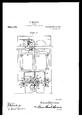
- Fig. 2 is a view of the improved rocking mechanism. shown in' assoclatlon with a furnace seen in front elevation.
- . 3 is a view in front elevation of the ratchet motion converter.
- Fig. 4' is a View in side elevation of the ratchet mechanism seen at Fig. 8.
- 5 is a fragmentary detail view of the cam which is associated with the ratchet motion converter seen at Figs. 3 and 4..
- Fig. 6 is a diametrical sectional'view through the cam and associated parts as see on line 6-6 of Fig. 5.
- Fig. 7 is a view in side elevation of the lock for connecting the constantly reciprocating plunger with the intermittently reciprocating plunger.
- Fig, 8 is a view in side elevation of a slight modification of the lock shown at Fig. 7.
- Fig. 7 is a view in front elevation of the ratchet motion converter.
- Fig. 4' is a View in side elevation of the ratchet mechanism seen at Fig. 8.
- 5 is a fragmentary detail view of the cam which is associated with the ratchet motion converter seen at Figs. 3
- Fig. 9 is a view in front elevation of a moditied means connecting the ratchet converter with the lock shown at Figs. 7 and 8.
- Fig. 10 is a top plan view of one embodiment of one of thevrefuse discharge sections.
- Fig. 11 is a. view in side elevation of the refuse discharge section shown at Fig. 10 with one corner broken away on line l1-11 to show the formation ofthe pockets.
- Fig. 12 is an inverted perspective view of the bar carrying the refuse dump sections. in side elevation of the bar carrying the refuse dump sections with one side broken away to show the. position of the sections relative to the bar.
- Fig. 14.15 a top plan view .of-one of the ash dump sections employed at the middle of the bar and used to connect the controlling link therewith.
- Fig. 15 is a view in side elevation of theron trolling link connected to the middle dump section shown at Fig. 14:.
- a hopper 15 is provided with a regulating curved plate 16 and a. pusher l7 operated by link 18 from the frame 14.
- the grate bars are connected as disclosed in the said patent by connecting similar grate bars end to end so that all of the grate bars forming the fuelsurface are rocked by' the links 11 connected to the central series of bars- While it is illustrated herein asdisclosed in the said patent and found asatisfactory and desirable form of fuel supporting surface and means for rocking the same it is to be I understood that this application is not confined to such formation of grate bars or fuel surface and that any approved form of fuel surface operated from any form of rocking I means maybe substituted.
- a well or pocket 20" is provided com )osed'of the walls 21 and 22, the latter of which is preferably the wall of the combustion chamber and the former of' refractory material supported by the beams--19.
- the well or pocket 20 is formed with-the sides 21 and 22 diverging downwardly so that the well. is wider at the bottom than at the top to prevent the clogging or lodging of cinders or like material-pushed from the fuel surface into the well or pocket.
- a rocking closure indicated as a whole in Fig. 1 as 23 is'employed" so that material passing downwardly along the fuel supporting surface will conform at the top substantially to the dotted line-2 4.
- the closure shown'as a whole at 23 is made up of supporting bar sections'shown at 24: in Figs. 1.2 and .13 having double walls with partitions 25 formed therein producing sockets '26 into which the webs 27 of the sections in the bars 21 until they are wori 1 corner of the wall 22. Under th loWB jeclge or corner of the wall 22 the pla ,p
- a rod 36 extends through the frfa'it' wall tofthe stoker at 37 and is providcd ;.-yt its lower or inner end with a curved extremity 38, the curvature of which corresponds substantially to the curvature of onc-halfof one of the sections of the closure 23 and provided with a hole 39 adapted to pivot upon the stud From an examination of Figs. 14. 15 and hit will be apparent that the curved extremity 38 with the hole engaging upon the stud 35 will produce with such, curved 'the frame l4, that the bar 36 be disposed considerably below the shaft 41 and a crank arm of the length required to connect such shaft with the rod 36 would give too great a throw to the rod and to the closure 23 con nected therewith.
- a link 4 is pivoted to'an ear 44 at the front of-the furnace structure and a lever 45 pivoted to the link.
- the lever 45 is also pivoted as at 30 46 to the rocking frame 14 and the rod 36 is pivoted to such lever 45 at either of the holes t7.
- the central bar 36 is rocked in unison and'similar amplitude with the side bars 36. All of the bars 36, both the central and side bars are pro'i ided with handles J-Sfor the purpose of manually ocking the closure 23 when desired by removing the pivot pins from the rods 36.
- a lock is brought into use consisting substantially of a bell-crank lever so, pivoted to thoslccre 53 as at 57 shown atl igs'i'and 8 and having one end weighted as at 58 soon in the same figures.
- the plunger is provided with a rigid pintle 59 and the upper part of the bell-cranklever 56 is provided with a notch or recess shown at Fi 7 as (30 and at Fig". 8 as (50' adapted to par: tially embrace the pintle 59. Fulcrulned upon the pintle '59 is a detent (31 provided with a notch 62 adapted.
- inginovenienta finger 34 is carried by the hopper 15 in position to engage the tail of the detent (31 upon the complet'ioi'i of its upward'strokeand to detach it froin the ])ll]l'l8
- the weighted end of the. lever 56 is raised by the link 65 actuated either by the spring 66 seen at Fim 1. or the weighted lever" 67 at Fig. '9, the
- weight i8 carried by such weighted lever 67 being sufficient to overhalance the weight 58 upon the bell crank lever 56.
- the link 64 is. connected with an arm (35), such connection being accomplishedfwhere the springfifi is employed by means of a link 'ifihaving one end pivoted to an arm 7l-carried by a rock shaft 72 while a similar arm 73 is nected with the, spring 66.
- the liuk is pivotally eon nectedwitl'i a lever 74: pivot-( das at 75 to the supporting frame 76 and also pivoted as at 7 6 to the weighted lever 67'.
- a cam 77 is mounted upon a shaft 78 transverse to the shaft 49 and provided. with one or more recesses 79 proportioned to permit a roller 80 carried by the lever 69 todrop therein. It will be apparent, therefore, that as the cam 77 rotates the lever 69 is permitted to intermittently drop to drop the weight 58 and. connect and lock together the sections of the plunger as above described.
- a ratchet Wheel81 is mounted rigidly-upon the shaft 78 and/is under: the action of the vertically recipro eating pawls- Si? and 83.
- a plurality of holes 90 are provided into which or any i of which pins may be inserted which will engage a guard 91 carried by one of the pawls 'as'83 so that when one of the pins in such holes 90 -engage such guard the pawl misses connection'with one of the ratchet-teeth.
- the raising of the lever 69 is permiltcd hyrcason of the sm-ing'tltr as shown t: Fig; I-orihc weighted lever 67 asshown at Fig. E) but immediately upon the unlocklog of the sections 52 'and 53 the weight or spring raises the weight-58 so that the parts 52 and 53 are not again locked together until 'drop.
- the grate bars and also the closure 23' ,Will give intermittent rocking motions, be- 7 tween which interlriittent mot-ions th'e 'partsj remain stationary and are permitted tolcool .tO'SliCll an extent that the grate bars d?) not burn out more rapidly in a mechanical sto'ker 'so intermittently operated than in other furnace structures employing similar grate bars.
- the intermittent. rockingflof the closure 21 is sullicient to discharge the ash from the pocket 20 and also to grind and discharge the clinkers but to retain the refuse within such pocket'ilO until any unconsumed fuel" which passes from the grate surface has been" finally consumed.
- the throw of bheclosure 51 may he varied so that i'f'it is found;
- rock-lug ash discharge are being operated only a fraction or the time that power for rocking such parts 1s used for one stoker only during such rocking movement and that by properly connecting a plurality of stokers in a single battery andto a single shaft 49 they may be so timed that they Will Work serially,-that is to say, that after the completion of operation ofone stoker the operation of a second stoker will be be- .gun and so on until all of the time between closure is rocked, and.
- What I claim is 1.
- a furnace the combination with a fire supporting surface and a bridge wall, of a Wall positioned at the inner end of said fire supporting. surface. defining, together with said bridge Wall, an ash receiving pocket, a closure and, ash discharge memher for the lower end bf said pocket formed so as to discharge ashes deposited thereon Whenever rocked, and means for rocking said closure.
- said pe-- riphery being formed with a plurality of means for engaging in said pocket and discharging the same laterally therefrom when said closure is rocked, and means for rocking the closure.
- a furnace the combination with an inclined fire supporting surface, of walls defining a pocket at the lower-end of said surface for receiving ashes therefrom, a segn'ient'al closure having an arc-shaped periphery pivotally mounted so as to move transversely of said pocket for disel'iargii'ig ashes from said pocket in a substantially horizontal direction when rocked, and means for rocking said closure transversely of said pocket.
- a closure and ash discharge member for the pocket adapted at all times to maintain-ashes ⁇ vithin'the pocket
- said pendant wall and said bridge wall delinlng a pocket with do ⁇ 'n ⁇ -'a rdly diverging sides.
Landscapes
- Engineering & Computer Science (AREA)
- Chemical & Material Sciences (AREA)
- Combustion & Propulsion (AREA)
- Mechanical Engineering (AREA)
- General Engineering & Computer Science (AREA)
- Incineration Of Waste (AREA)
Description
' W. MGGLAVE.
STOKBR. APPLH IATION FILED SEPT. 30, 1909.
' 984, 100. v Patented Feb. 14, 911.
6 SHEB,TSSHEET 1,
m me I 11 06 after/1 w:
ivil-1106500 W. MOGLAVE. STOKBE. APPLIOATION FILED SEPT. 30. 1909.
Patented Feb. 14, 1911.
6 SHEETSSHEET 2.
q as i v mcowm w I H V A L C G M W STOKBE.
APPLIOATIOH FILED SEPT. 30. 1909.
Patented Feb. 14, 1911.
q SHBETQPSHEET 4.
1 i-tncoow W. MQGLAVE.
STOKEE.
APPLICATION FILED SEPT. 30, 1909.
Patented Feb. 14, 1911.
6 $HEETSSHEET 6v QXMhww A n- F.
UNITED STATES ra rnnr OFFICE.
WILLIAM MGCLAVE, O15 SCRANTON. PENNSYLVANIA, ASSIGNOR TO MoCLAVE-BROOKS COMPANY, OF SGRANTON, PENNSYLVANIA, A CORPORATIDN OF PENNSYLVANIA.
STOKER.
Specification of Letters Patent.
Patented Feb. 14;, 1911.
Application filed September 30, 1909. Serial No. 520,296. v
To all whom it may concern:
Be it known that 1, WILLIAM MoCLAvn, a citizen of the United States, residing at Scranton, in the county of Lackawanna and State of Pennsylvania, have invented eertainnew and useful Improvements in Stokers; and I do hereby declare the following to he a fulh clear, and exact description of the invention, such as will enable others skilled in the art to which it appcrtains to makeand use the same.
This invention relates to stokers, and has for an object to provide a stoker embodying an inclined fuel supporting surface composed of rocking grate bars with means for introducing fuel at the upper end of vthe fuel supporting surface and with improved means for rocking the grate hars intermittently. i
A further object of the invention ,is to provide in, ,air intermittentrocking mecha nism for stoker grates means for varying the throw of the grates in different parts of the fuel supporting surface.
A further object of the invention is to provide a pocket at the lower end of the fuel supporting surface into which the residue is dmnped, such pocket being provided with inclined sides diverging downwardly and with means at the bottom of the pocket for intermittently discharging the refuse from the' pocket.
A further object of the invention is to provide at the bottom of: the refuse pocket a: rocking plate provided with ineans for discharging the refuse from the pocket with- ,out uncovering the lower opening of the pocket which is closed why such rocking plate.
A. further object ofthe invention is to pro,
vide means for intermittently rocking the refuse discharge coincidentally with the rocking of the grate bars.
A further ob'ect of the invention is to provide improved means employing a con-- stantly rotating shaft for actuatingithe several parts of the stokerwith improved means for connecting and disconnecting the parts from such rocking shaft to provide an intermittentactuation.
A further object of the-niventlon is to provldc nnrn-ovcd means for connecting and disconnecting the intermittent mechanism with and fromthe actuated parts.
, 1th these and other oh ccts in view, the niventlon comprises certain novel construe' tcrmittently operating mechanism in side elevation. Fig. 2 is a view of the improved rocking mechanism. shown in' assoclatlon with a furnace seen in front elevation. Fig.
. 3 is a view in front elevation of the ratchet motion converter. Fig. 4' is a View in side elevation of the ratchet mechanism seen at Fig. 8. 5 isa fragmentary detail view of the cam which is associated with the ratchet motion converter seen at Figs. 3 and 4.. Fig. 6 is a diametrical sectional'view through the cam and associated parts as see on line 6-6 of Fig. 5. Fig. 7 is a view in side elevation of the lock for connecting the constantly reciprocating plunger with the intermittently reciprocating plunger. Fig, 8 is a view in side elevation of a slight modification of the lock shown at Fig. 7. Fig. 9 is a view in front elevation of a moditied means connecting the ratchet converter with the lock shown at Figs. 7 and 8. Fig. 10 is a top plan view of one embodiment of one of thevrefuse discharge sections. Fig. 11 is a. view in side elevation of the refuse discharge section shown at Fig. 10 with one corner broken away on line l1-11 to show the formation ofthe pockets. Fig. 12 is an inverted perspective view of the bar carrying the refuse dump sections. in side elevation of the bar carrying the refuse dump sections with one side broken away to show the. position of the sections relative to the bar. Fig. 14.15 a top plan view .of-one of the ash dump sections employed at the middle of the bar and used to connect the controlling link therewith. Fig. 15 is a view in side elevation of theron trolling link connected to the middle dump section shown at Fig. 14:.
Like. characters of reference designate corresponding parts throughout- .the several Fig. 13 is a view are stationary and other alternate bars are rocking bars. As in the disclosure of the said patent the bars are also provided with links 11 which extend outwardly through the front of the furnace structure as at 12 and are connected with blocks 13 slidably mounted in the rocking frame 14, the same. as in the aforesaid patent.
Also as in the said Patent No. 849913 a hopper 15 is provided with a regulating curved plate 16 and a. pusher l7 operated by link 18 from the frame 14. Also as in the said patent when a fuel surface exceeding in width the length of one grate bar is to be employed the grate bars are connected as disclosed in the said patent by connecting similar grate bars end to end so that all of the grate bars forming the fuelsurface are rocked by' the links 11 connected to the central series of bars- While it is illustrated herein asdisclosed in the said patent and found asatisfactory and desirable form of fuel supporting surface and means for rocking the same it is to be I understood that this application is not confined to such formation of grate bars or fuel surface and that any approved form of fuel surface operated from any form of rocking I means maybe substituted. I
The beams 19 whieh'form the support of the rocking grates arecurveddownwardly at their lower ends and at the lower end of the fuel supporting surface a well or pocket 20"is provided com )osed'of the walls 21 and 22, the latter of which is preferably the wall of the combustion chamber and the former of' refractory material supported by the beams--19. Also as shown at Fig. 1 the well or pocket 20 is formed with-the sides 21 and 22 diverging downwardly so that the well. is wider at the bottom than at the top to prevent the clogging or lodging of cinders or like material-pushed from the fuel surface into the well or pocket. At the bottom of the well or pocket 20 a rocking closure indicated as a whole in Fig. 1 as 23 is'employed" so that material passing downwardly along the fuel supporting surface will conform at the top substantially to the dotted line-2 4.
and the material as it is pushed over the -:tion of such uneonsumed. fuel.
lower end of such fuel supporting, surface Into the pocket 20 will continue to occupy The shown is that even after p'ass'ing the entire length of the fuel supportln'g surface some of the fuel not consumed and when being supprn-lcd within the pocket 20 air is admitted between the closure 23 and the edges of the walls2l and 22 to complete the combus- The closure shown'as a whole at 23 is made up of supporting bar sections'shown at 24: in Figs. 1.2 and .13 having double walls with partitions 25 formed therein producing sockets '26 into which the webs 27 of the sections in the bars 21 until they are wori 1 corner of the wall 22. Under th loWB jeclge or corner of the wall 22 the pla ,p
dump sections are inserted such a web being shown in detail at Fig; 11 the sections bein g' provided with malleable studs 28 capableof being bent after being inserted in the sockets as indicated at Figs. 12 and 13 to retain the 7 or broken and it is desirable to remove themi f One configuration of the upper surface of the section is shown at Fig. 10 wherein something more than half of the surfaceiis gs provided with recesses 29 having converging inclined sides such rec'essesbeing separated by ridges or crests 30. The portion of th surface which is thus provided with the no eesse's 29 is that portion located under .tl wall 21 of the pocket. It will be noted fro; Fig. 1 that the lower edge or corner of th wall 21 is spaced at a greater distance from the top of the section than is the lower ed-g tion 31 of the sections is disposed. In d s charging material the closure is rocked upo the trunnions 32 but a little distance enough to uncover any portion of the lowe z e opening of the pocket 20, it being noted that the closures are of a dimension greater tha the transverse area of such pockets and tha a rocking motion is provided for without uncovering the lower side of the pocket... The recesses 29 engage the ash andcinde Contained in the pocket 20 and -as the closer 23 rocks downwardly in the directionindi cated by the arrow ash and ground e-id are carried by such closure under the come, of the wall 21 and discharged into 'the.a pit 33 under the fuel surface. As shown 3 Figs. 1, 10 and 11 it is not intended to d s, charge ash or refuse fromvthe rear wall the pocket 20 beneath the edgeof the wal 22 but it is to be understood, of course, that;
the present invention is not limited: to forming the pocket and closure so as to discharge upon one side onlybut co 11'1p1 'ehemls discharging upon both sides. vIt will. be app". out that even with the parts disposed angl proportioned as-sho\\-'1=i'at Fig. isomeggsh will be discharged under the .wall andjit is within the scope of the present invention, to increase the interval between thel oiueni fi edge of the wall 22 and the closure 23 also to inerease'the area of roughened surface upon the closure so that ash and ground cinders may be discharged upon both sidespl nilo provide for rocking the closure Elena/. 9
of the sections as shown at Fig. 14 is-.p11 -,i;
vided with a cut-out portion 34. such guts; out portion also being shown at Fig. 13-. d, I astud filo-is formed integral with the mogli- 0e fled section shownat Fig: l i'which section is preferably disposed so that thecut-pnflj} portion is ceI-itral of the bar as shownifltii' Fig. 1 A rod 36 extends through the frfa'it' wall tofthe stoker at 37 and is providcd ;.-yt its lower or inner end with a curved extremity 38, the curvature of which corresponds substantially to the curvature of onc-halfof one of the sections of the closure 23 and provided with a hole 39 adapted to pivot upon the stud From an examination of Figs. 14. 15 and hit will be apparent that the curved extremity 38 with the hole engaging upon the stud 35 will produce with such, curved 'the frame l4, that the bar 36 be disposed considerably below the shaft 41 and a crank arm of the length required to connect such shaft with the rod 36 would give too great a throw to the rod and to the closure 23 con nected therewith. To compensate a link 4 is pivoted to'an ear 44 at the front of-the furnace structure and a lever 45 pivoted to the link. The lever 45 is also pivoted as at 30 46 to the rocking frame 14 and the rod 36 is pivoted to such lever 45 at either of the holes t7. By employing this mechanism the central bar 36 is rocked in unison and'similar amplitude with the side bars 36. All of the bars 36, both the central and side bars are pro'i ided with handles J-Sfor the purpose of manually ocking the closure 23 when desired by removing the pivot pins from the rods 36.
It has been found from experiment that in mechanical stukers and especially in rocking grate stokers the grate bars burn out much more quickly than similar bars used in.
fuel supporting furnaces not mechanically rocke d. the cause for burning out more rapidly is the continued rocking of the bars whereby a compression and col'isequent raising of heat of'the fuel is accomplished and also by the continued agitation of the under surface of the fuel more heat directly upon the of the hers is greatly increased. Itis found desirable, lhoweverlat the moment of rocking .the'bars't o give them a .quick motion rather'than a. slow motion. For this in pose it is found necessary to have certain driving parts driven at sufficient speed to give to the bars the necessary speed of niohorthis purpose a constantly driven shaft in the sleeve 53 without transmitting any Ex 'ierimenthas also shown that (53.
tion, but to connect such driving means with- ,the bar actuating means only at intervals.
4%) somewhat in the nature of a line shaft is run along in frontof the several furnaces and stokeis forming the battery. At each of the furnaces a crank 50 is provided haring a wrist pin .Iil journaled in the bearing end of a ph'tuger 52 so that as the shaft 49 is contii'iuously rotated the plunger 52 is con tinuously reciprocated. At its lower end the plunger 52 telescopes within a sleeve 55} which forms in reality one section of the 'iluuger and which is pivoted as at M to brackets 55 rigid with the frame 14;. N01- mally the plunger 52 reciprocates freely with:
motion thereto but at such times as it is desirable to transmit motion tothe rocking parts a lock is brought into use consisting substantially of a bell-crank lever so, pivoted to thoslccre 53 as at 57 shown atl igs'i'and 8 and having one end weighted as at 58 soon in the same figures. The plunger is provided with a rigid pintle 59 and the upper part of the bell-cranklever 56 is provided with a notch or recess shown at Fi 7 as (30 and at Fig". 8 as (50' adapted to par: tially embrace the pintle 59. Fulcrulned upon the pintle '59 is a detent (31 provided with a notch 62 adapted. to engage upon a pin (33 carried by the bell-crank love and to maintain such bell cranklever with its aperture or (30 in association with the pintle 5!) whereby the sleeve is locked to the rcciproc-ating; plunger and to move therewitli, rocking the frame 14: and the stoker mechanism associated therewith.
As it is desirable to give the rocking frame it and its connected parts but a single rock: inginovenienta finger (34 is carried by the hopper 15 in position to engage the tail of the detent (31 upon the complet'ioi'i of its upward'strokeand to detach it froin the ])ll]l'l8 At the same time the weighted end of the. lever 56 is raised by the link 65 actuated either by the spring 66 seen at Fim 1. or the weighted lever" 67 at Fig. '9, the
weight i8 carried by such weighted lever 67 being sufficient to overhalance the weight 58 upon the bell crank lever 56. 1
For permitting the bell crank lever 56 to engage the pintle 5%) the link 64 is. connected with an arm (35), such connection being accomplishedfwhere the springfifi is employed by means of a link 'ifihaving one end pivoted to an arm 7l-carried by a rock shaft 72 while a similar arm 73 is nected with the, spring 66. In the form shownat Fig. 9 the liuk is pivotally eon nectedwitl'i a lever 74: pivot-( das at 75 to the supporting frame 76 and also pivoted as at 7 6 to the weighted lever 67'. To raise and lower the extremity of the lever 69 whereby the-link 65 is permitted to pivot'ally condrop to permit the weight 58 to connect the bell crank lever 56 with the pintle 59 a cam 77 is mounted upon a shaft 78 transverse to the shaft 49 and provided. with one or more recesses 79 proportioned to permit a roller 80 carried by the lever 69 todrop therein. It will be apparent, therefore, that as the cam 77 rotates the lever 69 is permitted to intermittently drop to drop the weight 58 and. connect and lock together the sections of the plunger as above described.
To rotatethe cam 77 a ratchet Wheel81 is mounted rigidly-upon the shaft 78 and/is under: the action of the vertically recipro eating pawls- Si? and 83. 'In the ratchetwheel 81 adjacent its periphery a plurality of holes 90 are provided into which or any i of which pins may be inserted which will engage a guard 91 carried by one of the pawls 'as'83 so that when one of the pins in such holes 90 -engage such guard the pawl misses connection'with one of the ratchet-teeth. By
inserting or removing pins from the hole 90 the speedat which the ratchet wheel '81 and consequently the cam 77 rotates may be varied.- The normal rotation of such cam and ratchetwheel under the. action of the reciprocating pawls is at the highest speed required and the speed of rotation wilhhe decreased by inserting one or more pins in the holes'flO. ltwill thus he apparent that with thesha'ft '49 constantly rotated and the plunger crmstautly irciproeated the sleeve. iii-twill he reclprocatml only when after re peated step-by step movenu'nts of the ratchet wheel 81 the. cam 77 is moved to such positionitha't the roller 80 drops into'the recesses 79 which permits the link 35 todrop and the lot-k to lock together the sections 52 and 53. tions produces a single reciprocation of the sleeve. 5 -3 and the parts connected therewith but upon coming to the upper extreme of its movement the linger (34- engages the detent (El and unlocks the detent 61 from the pintle (33L During;thesi'ngle reciprocation of the plunger 52-thc ratchet wheel'81 has been rotated .a step which has again raisedthe lever ($9. The raising of the lever 69, is permiltcd hyrcason of the sm-ing'tltr as shown t: Fig; I-orihc weighted lever 67 asshown at Fig. E) but immediately upon the unlocklog of the sections 52 'and 53 the weight or spring raises the weight-58 so that the parts 52 and 53 are not again locked together until 'drop.
substantially the same as the'level. of the This locking together of'the sec=' by the continued step by step movementof the cam 77 the lever. 69 is permitted to agairi By an mspection of the mechanism shown it will be apparent that the cam 77 is com tinually rotated with astep by step movement from the constantly rotating shaft 49 but that'the step by step movement may be varied'by the. insertion or Withdrawal of pins from the hples 90. Whenthe cam 77 by such step'iy step movement brings one of the/recesses 79 into position to receive theroller 80 the lever 69 again drops andmo tion is transmitted at the speed of the constantly rotated shaft 49 to rock the various parts connected with the sleeve 53. By this means the grate bars and also the closure 23' ,Will give intermittent rocking motions, be- 7 tween which interlriittent mot-ions th'e 'partsj remain stationary and are permitted tolcool .tO'SliCll an extent that the grate bars d?) not burn out more rapidly in a mechanical sto'ker 'so intermittently operated than in other furnace structures employing similar grate bars.
Also the intermittent. rockingflof the closure 21 is sullicient to discharge the ash from the pocket 20 and also to grind and discharge the clinkers but to retain the refuse within such pocket'ilO until any unconsumed fuel" which passes from the grate surface has been" finally consumed.
As ahore described the throw of bheclosure 51 may he varied so that i'f'it is found;
the rcluse consisting of ash. clinlters, etc, is' not being discharged sulhciently fast to maintain the level (it the vrefuse within the upon the surface the throw may be increased,
and. it may also he decreased if it is found that the refuse is being discharged too rapidly to depressthe level of the refuse 1n the -L'l\'(i-Hi' substantially the level of the fuel pocket below the fuel surface, itbeing found,
desirable to maintain the level of the refuse fuel surface. it isalso desirable to give the grate bars at dili'erent parts of the fuel surface throws oli varying aniiplitude and this is :iccomplished as in patent No. 849913 in moving the blocks 13 nearer or farthert'i'onrthc pivot ot' the frame Ha As shown I at Fig. l the pivots ot' the links ll to the blocks 13 coincide with the pivot of the frame l 'lso that no throw is given to the grate bars in that posit-ion. As the blocks are moved upwardly within the frame 1 however, the throw of the grate harsis increasc il and as each of tl'iegrate bars connected with a'separate block separately adjustable in the frame 1-l each may be givena throw {it d1 llfercnt. lllllplli'lhle as-described n said patent" 1 It will be' ap mrent. that as the rocking grates and. rock-lug ash discharge are being operated only a fraction or the time that power for rocking such parts 1s used for one stoker only during such rocking movement and that by properly connecting a plurality of stokers in a single battery andto a single shaft 49 they may be so timed that they Will Work serially,-that is to say, that after the completion of operation ofone stoker the operation of a second stoker will be be- .gun and so on until all of the time between closure is rocked, and.
Wall, of a We] reciprocations has been used up when the first stoker 'Will again be operated.
What I claim is 1. In a furnace, the combination with a fire supporting surface and a bridge wall, of a Wall positioned at the inner end of said fire supporting. surface. defining, together with said bridge Wall, an ash receiving pocket, a closure and, ash discharge memher for the lower end bf said pocket formed so as to discharge ashes deposited thereon Whenever rocked, and means for rocking said closure.
2. In a furnace, inclined fire supporting surface anda brid 1 arranged at the lower end of said inclined fire supporting surface de-" fining, together With said bridge wall, an ash receiving-pocket, a rocking closure arranged at the bottom ofsaid pocket and so formed as to remove ashes from said pocketwhen the'closure is rocked, said closure being proportioned to extend entirely across the bottom of-s'aid pocket, but with one side spaced therefrom. whereby the ashes in said pocket/may be supported at all times and discharged when said closure means for rocking said closure rocked, and for causing pocket. I
' 3. In a. furnace, the combination with an incl ined fire supporting surface and a bridge wall, of a Wall arranged at the lower end of said inclined fire supportingsurface defining, together with said-bridge Wall, a
a discharge of ashes from said pocket formed With downwardly .c'onv e'rga ing sides extending substantially the entire length of said side Walls,,said pocket being adapted to receive ashes from said fire suportin surface a rockin closure for the bottom of said pocket formed so as to discharge ashesfrom said pocket Whenever the means for rocking said closure.
4'. In a furnace,
4 of a pocket defined, by theglower edge of said inclined fire supporting surface and thefbridge 'Wall of said furnace, charge member for closing the dischafge; member, and
In a flfurnace, the combination with the-combination with an the combination with an. 7 inclined firesuptvorting surface,
a segmental closure and dis operating beneath the pocketpocket against a vertical dis; charge of ashes thereon for causing a disupon rockingsaid segmental charge therefrom.
"formed with ash 'upon oscillation, and means inclined .flre supporting surface, of walls arrangedto form a pocket atthe lower end of said surface, a closure aud ash discharge member operating beneath said pocket for closing said pocket against a vertical dis charge of'ashes but causing a discharge h'u-izoutally of-ashes upon rocking said closure, and inealisfor rocking said closure.
6. In a furnace. the combination with an inclined fire supporting surface, of Walls delining a pocket at the lower end of said fire sup 'iorting surface. a rocking closure and ash discharge member arrangcd at the bnttom of said pocket for uormall preventing ashes from escaping from said pocket in a Vertical direction but causing a lateral discharge of ashes fronisaid pocket upon a rocking movement of the closure and ash discharge member, and means for rocking said closure and discharge member adapted to movcsaid closure and discharge member until the same permits the free vertical discharge of ashes from said pocket.
7. In a furnace, the combination with an inclined fire. supporting surface, of wall idefining an ash pocketarranged at the bottom of said surface, a closure and ash discharge member curred at its periphery mounted at the bottom of said pocket and centrally thereof, so as V to substantially close the pocket, said closure and ash discharge-member being' formed larger than the distance across said pocket, and means for rocking said closure and ash discharge member with an amplitude normally not greater than the excess of the closure and ash discharge member over the pocket, the rocking of said closure and ash discharge member-causing a discharge of ashes from said pocket. 7'
8. In afurnace, the combination.with a fire supporting surface, of Wallsdefining a pocket at-the inner end of said fire supporting surface, said pocket being open at the top and bottom, a pivotally mounted segmental'member arranged at the bottom of said pocket adapted to act as an ash discharge member, and also as a closure for the pocket, said closure being formed with recesses therein for causing the closure toremove ashes from said pocket ivhen the closure is rocked, and means to rock said closure so as to discharge ashes from said pocket substantially horizontally but maintain closed the lower end of the pocket against a vertical dis- 9. In a.furnace,'the combination With'a fire supporting surface, of Walls defining a pocket at the nner end of said fire supporting surface arranged said surface, a p-ivotally mounted closure positionedin the bottom;
of ashes from the pocket or oscillating closureto receive ashes from pocket in a downward direction, said pe-- riphery being formed with a plurality of means for engaging in said pocket and discharging the same laterally therefrom when said closure is rocked, and means for rocking the closure.
11.111 a furnace, the combination with an inclined fire supporting surface, of walls defining a pocket at the lower-end of said surface for receiving ashes therefrom, a segn'ient'al closure having an arc-shaped periphery pivotally mounted so as to move transversely of said pocket for disel'iargii'ig ashes from said pocket in a substantially horizontal direction when rocked, and means for rocking said closure transversely of said pocket. i a
12. In a furnace, the combination with a tire supporting surface, of walls arranged at the inner end of the fire supporting surface defining" an ash receiving pocket formed with diverging sides, said pocket being largerat the bottom thanat the top, a closure, and ash discharge memberfor the bottom of said pocket adapted at all times to contain ashes Within the pocket'an'd to-discharge horizontally a portion of the ashes from the bottom of the pocket when the closure and ash discharge member is rocked, and meansfor rocking said closure and ash discharge member.
13. In a furnace, the combination with a tire supporting surface, vof walls definingan ash receiving pocket..hav1ng sides d1verg-.
ing'downwardly, a closure and ash discharge member for the pocket adapted at all times to maintain-ashes \vithin'the pocket, and
means for rocking the closure and ash discharge mcinber for discharging a portion of the ashes from the bottom of said pocket. 4 v
' 14. In a l'urnzwc, the combination with a tire su n'iorting surface, of" walls defining an ash receiving pocket having sides diverging dmvnn'ardly, a closure for. the bottom of said pocket so proportioned and constructed.
relative to the pocket thatthe ash in the pocket is prevented from discharging in a verticaldirection from said pocket, but is discharged from one side of the pocket upon arocking inoven'icnt of the closure, and means for -rocking said closure.
.15. In afnrnace, the combination with a "fire su 'niorting surface and a bridge-avail,
of a pendant wall having the upper edge .7
thereof arranged jadjacent 't'heinner edge of said lire supporting surface. said pendant wall and said bridge wall delinlng a pocket with do\\'n\\-'a rdly diverging sides. a rocking
Priority Applications (2)
| Application Number | Priority Date | Filing Date | Title |
|---|---|---|---|
| US52029609A US984100A (en) | 1909-09-30 | 1909-09-30 | Stoker. |
| US541062A US988275A (en) | 1909-09-30 | 1910-01-31 | Mechanical movement for automatic stokers. |
Applications Claiming Priority (1)
| Application Number | Priority Date | Filing Date | Title |
|---|---|---|---|
| US52029609A US984100A (en) | 1909-09-30 | 1909-09-30 | Stoker. |
Publications (1)
| Publication Number | Publication Date |
|---|---|
| US984100A true US984100A (en) | 1911-02-14 |
Family
ID=3052452
Family Applications (1)
| Application Number | Title | Priority Date | Filing Date |
|---|---|---|---|
| US52029609A Expired - Lifetime US984100A (en) | 1909-09-30 | 1909-09-30 | Stoker. |
Country Status (1)
| Country | Link |
|---|---|
| US (1) | US984100A (en) |
-
1909
- 1909-09-30 US US52029609A patent/US984100A/en not_active Expired - Lifetime
Similar Documents
| Publication | Publication Date | Title |
|---|---|---|
| US984100A (en) | Stoker. | |
| US657679A (en) | Furnace. | |
| US700831A (en) | Furnace. | |
| US1518024A (en) | Stoker | |
| US1318579A (en) | mcclave | |
| US409304A (en) | Steam boiler furnace or other furnaces | |
| US409650A (en) | Furnace | |
| US1186971A (en) | Mechanical stoker. | |
| US1239612A (en) | Fuel-feeding device. | |
| US447544A (en) | Island | |
| US1025841A (en) | Fuel-feeding mechanism. | |
| US403840A (en) | henderson | |
| US838679A (en) | Furnace. | |
| US565253A (en) | ayres | |
| US1318580A (en) | Planooftaph co | |
| US830705A (en) | Furnace-grate. | |
| US690582A (en) | Mechanical stoker. | |
| US631901A (en) | Furnace. | |
| US711668A (en) | Mechanical stoker. | |
| US955388A (en) | Mechanical stoker. | |
| US1088445A (en) | Stoking-grate for furnaces. | |
| US1165792A (en) | Stoking mechanism for furnaces. | |
| US449157A (en) | Automatic stoker | |
| US642260A (en) | Furnace. | |
| US540669A (en) | Furnace |