US9833127B2 - Wire connection device, camera head and endoscopic device - Google Patents
Wire connection device, camera head and endoscopic device Download PDFInfo
- Publication number
- US9833127B2 US9833127B2 US14/628,818 US201514628818A US9833127B2 US 9833127 B2 US9833127 B2 US 9833127B2 US 201514628818 A US201514628818 A US 201514628818A US 9833127 B2 US9833127 B2 US 9833127B2
- Authority
- US
- United States
- Prior art keywords
- contacts
- differential
- female
- row
- contact
- Prior art date
- Legal status (The legal status is an assumption and is not a legal conclusion. Google has not performed a legal analysis and makes no representation as to the accuracy of the status listed.)
- Expired - Fee Related, expires
Links
Images


Classifications
-
- A—HUMAN NECESSITIES
- A61—MEDICAL OR VETERINARY SCIENCE; HYGIENE
- A61B—DIAGNOSIS; SURGERY; IDENTIFICATION
- A61B1/00—Instruments for performing medical examinations of the interior of cavities or tubes of the body by visual or photographical inspection, e.g. endoscopes; Illuminating arrangements therefor
- A61B1/00112—Connection or coupling means
- A61B1/00121—Connectors, fasteners and adapters, e.g. on the endoscope handle
- A61B1/00124—Connectors, fasteners and adapters, e.g. on the endoscope handle electrical, e.g. electrical plug-and-socket connection
-
- A—HUMAN NECESSITIES
- A61—MEDICAL OR VETERINARY SCIENCE; HYGIENE
- A61B—DIAGNOSIS; SURGERY; IDENTIFICATION
- A61B1/00—Instruments for performing medical examinations of the interior of cavities or tubes of the body by visual or photographical inspection, e.g. endoscopes; Illuminating arrangements therefor
- A61B1/04—Instruments for performing medical examinations of the interior of cavities or tubes of the body by visual or photographical inspection, e.g. endoscopes; Illuminating arrangements therefor combined with photographic or television appliances
- A61B1/042—Instruments for performing medical examinations of the interior of cavities or tubes of the body by visual or photographical inspection, e.g. endoscopes; Illuminating arrangements therefor combined with photographic or television appliances characterised by a proximal camera, e.g. a CCD camera
-
- H—ELECTRICITY
- H01—ELECTRIC ELEMENTS
- H01R—ELECTRICALLY-CONDUCTIVE CONNECTIONS; STRUCTURAL ASSOCIATIONS OF A PLURALITY OF MUTUALLY-INSULATED ELECTRICAL CONNECTING ELEMENTS; COUPLING DEVICES; CURRENT COLLECTORS
- H01R13/00—Details of coupling devices of the kinds covered by groups H01R12/70 or H01R24/00 - H01R33/00
- H01R13/646—Details of coupling devices of the kinds covered by groups H01R12/70 or H01R24/00 - H01R33/00 specially adapted for high-frequency, e.g. structures providing an impedance match or phase match
- H01R13/6461—Means for preventing cross-talk
- H01R13/6471—Means for preventing cross-talk by special arrangement of ground and signal conductors, e.g. GSGS [Ground-Signal-Ground-Signal]
-
- H—ELECTRICITY
- H04—ELECTRIC COMMUNICATION TECHNIQUE
- H04N—PICTORIAL COMMUNICATION, e.g. TELEVISION
- H04N23/00—Cameras or camera modules comprising electronic image sensors; Control thereof
- H04N23/50—Constructional details
-
- H—ELECTRICITY
- H04—ELECTRIC COMMUNICATION TECHNIQUE
- H04N—PICTORIAL COMMUNICATION, e.g. TELEVISION
- H04N23/00—Cameras or camera modules comprising electronic image sensors; Control thereof
- H04N23/50—Constructional details
- H04N23/555—Constructional details for picking-up images in sites, inaccessible due to their dimensions or hazardous conditions, e.g. endoscopes or borescopes
-
- H04N5/2251—
-
- H—ELECTRICITY
- H04—ELECTRIC COMMUNICATION TECHNIQUE
- H04N—PICTORIAL COMMUNICATION, e.g. TELEVISION
- H04N7/00—Television systems
- H04N7/10—Adaptations for transmission by electrical cable
- H04N7/102—Circuits therefor, e.g. noise reducers, equalisers, amplifiers
-
- H04N2005/2255—
Definitions
- the present disclosure relates to wire connection device, a camera head and an endoscopic device.
- the connector described in JP2010-287560A includes multiple contacts arranged side by side in a row.
- the multiple contacts include multiple pairs of differential contacts and multiple ground contacts.
- To the multiple pairs of differential contacts multiple pairs of differential signals are respectively allocated.
- Each of the multiple ground contacts, to which ground is allocated, is placed between a pair of differential contacts and another pair of differential contacts.
- JP2010-287560A has a problem of difficulty in downsizing since the arrangement of multiple contacts arranged side by side in a row increases width dimension in the side-by-side arrangement direction.
- a wire connection device a camera head and an endoscopic device which are capable of preventing signal deterioration while achieving downsizing.
- a wire connection device including an outer frame that has a tubular shape, and a plurality of contacts that are provided in the outer frame, and that have a plurality of pairs of differential contacts to which a plurality of pairs of differential signals are respectively allocated, and a plurality of ground contacts each to which ground is allocated.
- the plurality of contacts are arranged side by side in two rows in a manner that the differential contacts of each pair can be adjacent to each other and in a manner that the number of the ground contacts adjacent to one of the differential contacts of each pair is equal to the number of the ground contacts adjacent to the other one of the differential contacts of the pair.
- the plurality of contacts when viewed from the direction along the central axis of the outer frame, may be arranged so as to constitute part of an equilateral triangular lattice where intervals of mutually adjacent lattice points are identical.
- the plurality of pairs of differential contacts may be arranged in a manner that one of the differential contacts of each pair is arranged in a first row of the two rows while the other one of the differential contacts of the pair is arranged in a second row of the two rows.
- the plurality of pairs of differential contacts may be arranged in a manner that both the differential contacts of each pair are arranged in either of a first row and a second row of the two rows.
- each of the plurality of contacts when viewed from the direction along the central axis of the outer frame, each of the plurality of contacts may be formed of a female contact including a first contact portion that has an L shape and that has a first sidewall portion extending in a side-by-side arrangement direction of either of a first row and a second row of the two rows, and a second sidewall portion crossing the first sidewall portion.
- the plurality of contacts may be arranged in a manner that separation distances between each two of the second sidewall portions mutually adjacent in the side-by-side arrangement direction are identical.
- each of the plurality of contacts may be formed of a female contact including a second contact portion that has a plate shape extending in a side-by-side arrangement direction of either of a first row and a second row of the two rows.
- each of the plurality of contacts when viewed from the direction along the central axis of the outer frame, may be formed of a female contact including a third contact portion that has a U shape and that has a base portion extending in a side-by-side arrangement direction of either of a first row and a second row of the two rows, and a pair of third sidewall portions erecting from the base portion and facing to each other in the side-by-side arrangement direction.
- the plurality of pairs of differential contacts may be arranged in a manner that one of the differential contacts of each pair is arranged in the first row while the other one of the differential contacts of the pair is arranged in the second row.
- the one differential contact and the other differential contact may be arranged symmetrically with respect to a point positioned at a center between the one differential contact and the other differential contact.
- the plurality of contacts when viewed from the direction along the central axis of the outer frame, may be arranged in a manner that the number of the ground contacts adjacent to one of the differential contacts of each pair and the number of the ground contacts adjacent to the other one of the differential contacts of the pair are set to one.
- a camera head used in an endoscope including the wire connection device, and an image sensor electrically connected to the plurality of contacts.
- the wire connection device may be formed of two connectors mechanically and electrically connected to each other, the connectors being a first connector and a second connector.
- an endoscopic device including the camera head.
- the multiple contacts are arranged side by side in two rows when viewed from the direction along the central axis of the outer frame.
- an increase in width dimension in the side-by-side arrangement direction can be avoided as compared to a wire connection device (the connector described in JP2010-287560A, for example) in which multiple contacts are arranged side by side in a row.
- the multiple contacts are arranged so that the differential contacts of each pair can be adjacent to each other and so that the number of the ground contacts adjacent to one of the differential contacts of each pair can be equal to the number of the ground contacts adjacent to the other one of the differential contacts of the pair.
- the number of so-called ground guards for each differential signal can be fixed, and consequently signal deterioration can be prevented.
- the wire connection device has an effect of preventing signal deterioration while achieving downsizing.
- the camera head according to an embodiment of the present disclosure includes the wire connection device, thus having a similar effect.
- the endoscopic device includes the camera head, thus having a similar effect.
- FIG. 1 shows a schematic configuration of an endoscopic device according to an embodiment of the present disclosure
- FIG. 2 is a perspective view, as viewed from the base-end side (side to which a composite cable is connected), of a camera head shown in FIG. 1 ;
- FIG. 3 is a perspective view, as viewed from the base-end side (side to which a photoelectric composite module is connected), of an airtight part shown in FIG. 2 ;
- FIG. 4 is a perspective view, as viewed from the inside of the airtight part, of a hermetic connector shown in FIG. 3 ;
- FIG. 5 is a view, as viewed from the outside (side to which the composite cable is connected) of the airtight part, of the hermetic connector shown in FIG. 3 ;
- FIG. 6 is a perspective view, as viewed from the front-end side (side to which the airtight part is connected), of the photoelectric composite module according to an embodiment of the present disclosure
- FIG. 7 is an exploded perspective view, as viewed from the base-end side (side to which the composite cable is connected), of the internal structure of the photoelectric composite module shown in FIG. 6 ;
- FIG. 8 is a perspective view, as viewed from the base-end side (side where first and second printed circuit boards are arranged), of the receptacle shown in FIGS. 6 and 7 ;
- FIG. 9 shows an array state of multiple female contacts shown in FIG. 8 ;
- FIG. 10 is a diagram for illustrating the arrangement of the multiple first female contacts shown in FIGS. 8 and 9 , and the allocation of signals and ground to the multiple first female contacts;
- FIG. 11 shows a modification of an embodiment of the present disclosure
- FIG. 12 shows a modification of an embodiment of the present disclosure
- FIG. 13 shows a modification of an embodiment of the present disclosure.
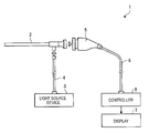
- FIG. 1 shows a schematic configuration of an endoscopic device 1 according to an embodiment of the present disclosure.
- the endoscopic device 1 is an apparatus used in medical fields to observe the interior of an observation object (interior of a living body) such as a human being.
- an endoscopic device using a rigid scope insertion part 2
- the endoscopic device 1 is not limited thereto, but may be an endoscopic device using a flexible scope (not shown).
- the endoscopic device 1 includes the insertion part 2 , a light source device 3 , a light guide 4 , a camera head 5 , a composite cable 6 , a display 7 and a controller 8 .
- the insertion part 2 being rigid and having an elongated shape, is inserted into an observation object.
- An optical system for condensing light to form an object image is provided inside the insertion part 2 .
- the light source device 3 is connected to one end of the light guide 4 , and supplies the one end of the light guide 4 with light to illuminate the interior of the observation object.
- the other end is detachably connected to the insertion part 2 .
- the light guide 4 transmits light supplied from the light source device 3 from the one end to the other end, thereby supplying the light to the insertion part 2 .
- the light supplied to the insertion part 2 is emitted from the distal end of the insertion part 2 , and thereby the interior of the observation object is irradiated with the light.
- the light (object image) with which the interior of the observation object is irradiated is condensed by the optical system in the insertion part 2 .
- the camera head 5 is detachably connected to the base end of the insertion part 2 . Under control of the controller 8 , the camera head 5 images the object image formed with light condensed by the insertion part 2 , then photoelectrically converts imaging signals (electrical signals) obtained by the imaging into optical signals, and outputs the optical signals.
- imaging signals electrical signals
- a differential transmission system is employed. Accordingly, information (imaging signals (electrical signals and optical signals)) obtained by imaging by the camera head 5 is transmitted to the controller 8 through the composite cable 6 as multiple pairs of differential signals (+) and differential signals ( ⁇ ).
- the differential signal (+) and the differential signal ( ⁇ ) of each pair are signals having mutually opposite phases.
- the composite cable 6 has multiple optical fibers 61 (see FIG. 7 ) and multiple electrical signal cables 62 (see FIG. 7 ) inside a jacket 6 A (see FIG. 7 ), which is the outermost layer.
- One end of the composite cable 6 is detachably connected to the controller 8 while the other end is detachably connected to the camera head 5 .
- the multiple optical fibers 61 are arranged at a center position of the composite cable 6 in a cross sectional view of the composite cable 6 , and used for transmitting optical signals between the camera head 5 and the controller 8 .
- the multiple electrical signal cables 62 are arranged around the multiple optical fibers 61 in a cross sectional view of the composite cable 6 , and used for transmitting electrical signals between the camera head 5 and the controller 8 .
- the display 7 displays an image under control of the controller 8 .
- the controller 8 acquires optical signals (differential signals (+) and differential signals ( ⁇ )) outputted from the camera head 5 through the multiple optical fibers 61 , and photoelectrically converts the optical signals to electrical signals. Then, the controller 8 performs predetermined processing on the photoelectrically converted electrical signals, thereby causing the display 7 to display an image imaged by the camera head 5 . Meanwhile, the controller 8 outputs control signals and the like (electrical signals) to the camera head 5 through the multiple electrical signal cables 62 .
- FIG. 2 is a perspective view, as viewed from the base-end side (side to which the composite cable 6 is connected), of the camera head 5 .
- the camera head 5 includes a coupler part 51 , an airtight part 52 and a photoelectric composite module 9 (see FIG. 6 ).
- FIG. 2 shows the state where a cover part 53 , having a tubular shape to cover the photoelectric composite module 9 and the base-end side of the airtight part 52 , is attached, thus not showing the photoelectric composite module 9 .
- the coupler part 51 is used for detachably connecting the camera head 5 to the base end of the insertion part 2 , and provided at the front end of the camera head 5 .
- FIG. 3 is a perspective view, as viewed from the base-end side (side to which the photoelectric composite module 9 is connected), of the airtight part 52 .
- the airtight part 52 includes a casing 521 constituting the exterior of the airtight part 52 , a hermetic connector 522 ( FIG. 3 ) mounted on the casing 521 , and parts housed in the casing 521 such as a lens unit (not shown), a driving motor (not shown) and an image sensor 523 (see FIG. 4 ).
- the lens unit forms an object image with light condensed by the insertion part 2 onto an imaging surface of the image sensor 523 .
- the lens unit is movable in the optical axis direction.
- the driving motor moves the lens unit along the optical axis when any of switches 521 A to 521 D ( FIGS. 2 and 3 ), provided to be exposed on the outer surface of the casing 521 , is pressed, thereby adjusting a focal distance and a focus of the lens unit.
- the image sensor 523 includes a charge coupled device (CCD) or a complementary metal oxide semiconductor (CMOS), a signal processing unit and the like.
- CCD charge coupled device
- CMOS complementary metal oxide semiconductor
- the CCD or CMOS receives light condensed by the lens unit and converts the light into the electrical signals.
- the signal processing unit performs signal processing on the electrical signals outputted by the CCD or CMOS, and outputs multiple pairs of differential signals (+) and differential signals ( ⁇ ).
- FIG. 4 is a perspective view, as viewed from the inside of the airtight part 52 , of the hermetic connector 522 .
- FIG. 5 is a view, as viewed from the outside (side to which the composite cable 6 is connected) of the airtight part 52 , of the hermetic connector 522 .
- the hermetic connector 522 being a member equivalent to a wire connection device (first connector) according to an embodiment of the present disclosure, is mounted on the base-end side (side to which the photoelectric composite module 9 is connected) of the casing 521 as shown in FIG. 3 .
- This hermetic connector 522 is a round connector and includes a second outer frame 522 A, a plate body 522 B and multiple male contacts 522 C as shown in FIGS. 3 to 5 .
- the second outer frame 522 A is made of a metal material and has a circular cylindrical shape. Note that the shape of the second outer frame 522 A is not limited to a circular cylindrical shape but may be any tubular shape. Specifically, the second outer frame 522 A may be a tubular body having another cross-sectional shape such as an ellipse, a quadrangle and a polygon.
- the plate body 522 B is made of a metal material and has a disc shape.
- the plate body 522 B closes the inside of the second outer frame 522 A.
- multiple openings 522 B 1 through which the multiple male contacts 522 C are respectively inserted are formed in this plate body 522 B.
- Each of these multiple openings 522 B 1 has a round shape in a plan view. As shown in FIG. 5 , with the multiple male contacts 522 C inserted through the multiple openings 522 B 1 , the multiple openings 522 B 1 are sealed by multiple insulating members 522 B 2 made of an insulating material (glass material in this embodiment) and each having a round shape, respectively.
- Each of the multiple male contacts 522 C has a columnar shape.
- the multiple male contacts 522 C are fitted to the plate body 522 B in the state where the male contacts 522 C are respectively inserted through the multiple openings 522 B 1 and insulated from one another by the multiple insulating members 522 B 2 .
- first male contacts 522 D the male contacts 522 C provided in a first area Ar 1
- second male contacts 522 E the male contacts 522 C provided in two second areas Ar 2
- first area Ar 1 is indicated by the dashed line
- second areas Ar 2 are indicated by the two-dot chain line.
- the first area Ar 1 is a band-shaped area in the second outer frame 522 A when viewed from the direction along a central axis Ax of the second outer frame 522 A.
- the band-shaped area includes the central axis Ax and extends in a first direction (right-left direction in FIGS. 4 and 5 ) orthogonal to the central axis Ax.
- the two second areas Ar 2 are areas other than the first area Ar 1 in the second outer frame 522 A. Each of the second areas Ar 2 extends in the first direction to be parallel to the first area Ar 1 .
- Each of the multiple first male contacts 522 D is a member equivalent to a contact according to an embodiment of the present disclosure.
- the multiple first male contacts 522 D are arranged in two rows which are side by side in the up-down direction in FIG. 4 so as to constitute part of an equilateral triangular lattice where the interval of mutually adjacent lattice points is fixed (so that the multiple first male contacts 522 D are respectively arranged at lattice points constituting part of the equilateral triangular lattice).
- first male contacts 522 D arranged side by side in the first row which is the upper one, are arranged side by side at a first pitch P 1 ( FIGS. 4 and 5 ).
- first male contacts 522 D arranged side by side in the first row are arranged side by side at a first pitch P 1 ( FIGS. 4 and 5 ).
- the multiple (five in this embodiment) first male contacts 522 D arranged side by side in the second row which is the lower one, are arranged side by side at the first pitch P 1 , too.
- each first male contact 522 D in the second row is arranged at a center position between the two first male contacts 522 D that are arranged side by side in the first row and that are adjacent to this first male contact 522 D in the second row, when viewed from the upper side of FIGS. 4 and 5 .
- the multiple first male contacts 522 D as described above are contacts used for differential transmission.
- the first male contacts 522 D to which differential signals (+) are allocated will be described as male-side first differential contacts 522 F ( FIG. 5 ).
- the first male contacts 522 D to which differential signals ( ⁇ ) are allocated will be described as male-side second differential contacts 522 G ( FIG. 5 ).
- the first male contacts 522 D to which ground is allocated will be described as male-side ground contacts 522 H ( FIG. 5 ).
- the arrangement (array) of the male-side first differential contacts 522 F, the male-side second differential contacts 522 G and the male-side ground contacts 522 H is similar to that of female-side first differential contacts 916 , female-side second differential contacts 917 and female-side ground contacts 918 , which constitute multiple first female contacts 914 . This arrangement will be described later.
- the openings 522 B 1 are formed so that an opening area size (diameter) of each of the openings 522 B 1 through which the male-side first and second differential contacts 522 F and 522 G are inserted can be different from that of each of the openings 522 B 1 through which the male-side ground contacts 522 H are inserted, as shown in FIG. 5 .
- the insulating members 522 B 2 are also formed in different sizes.
- the openings 522 B 1 through which the male-side first and second differential contacts 522 F and 522 G are inserted are formed in the same opening area size (diameter). Meanwhile, the openings 522 B 1 through which the male-side ground contacts 522 H are inserted are formed in a smaller opening area size (diameter) than the openings 522 B 1 through which the male-side first and second differential contacts 522 F and 522 G are inserted.
- the openings 522 B 1 through which the multiple second male contacts 522 E are inserted are formed in the same opening area size (diameter) as the openings 522 B 1 through which the male-side ground contacts 522 H are inserted, as shown in FIG. 5 .
- the multiple second male contacts 522 E are arranged in two rows which are side by side in the up-down direction in FIG. 4 .
- the multiple second male contacts 522 E arranged side by side in the first row which is the upper one, are arranged side by side at a second pitch P 2 ( FIG. 4 ), which is smaller than the first pitch P 1 .
- the multiple second male contacts 522 E arranged side by side in the second row which is the lower one, are arranged side by side at the second pitch P 2 , too.
- each second male contact 522 E in the second row is arranged at a center position between the two second male contacts 522 E that are arranged side by side in the first row and that are adjacent to this second male contact 522 E in the second row, when viewed from the upper side of FIG. 4 .
- the multiple second male contacts 522 E arranged in the upper one of the second areas Ar 2 in FIG. 4 are arranged symmetrically to the multiple second male contacts 522 E arranged in the lower one of the second areas Ar 2 with respect to a plane passing through the central axis Ax and being parallel to the side-by-side arrangement direction of the second male contacts 522 E.
- an airtight-part side printed circuit board 524 which relays communication between (is electrically connected between) the multiple male contacts 522 C and the image sensor 523 , is mounted on the hermetic connector 522 at the side inside the airtight part 52 .
- the airtight-part side printed circuit board 524 relays, to the multiple first male contacts 522 D, imaging signals (multiple pairs of differential signals (+) and differential signals ( ⁇ )) outputted by the image sensor 523 .
- the airtight-part side printed circuit board 524 relays, to the image sensor 523 , control signals and the like (electrical signals) outputted by the controller 8 through the composite cable 6 , the photoelectric composite module 9 and the multiple second male contacts 522 E.
- FIG. 6 is a perspective view, as viewed from the front-end side (side to which the airtight part 52 is connected), of the photoelectric composite module 9 .
- FIG. 7 is an exploded perspective view, as viewed from the base-end side (side to which the composite cable 6 is connected), of the internal structure of the photoelectric composite module 9 .
- the photoelectric composite module 9 is mechanically and electrically connected to the hermetic connector 522 .
- the photoelectric composite module 9 converts imaging signals (multiple pairs of differential signals (+) and differential signals ( ⁇ )) outputted by the image sensor 523 into optical signals, and then outputs the optical signals to the composite cable 6 (multiple optical fibers 61 ).
- the photoelectric composite module 9 relays, to the hermetic connector 522 (image sensor 523 ), control signals and the like (electrical signals) outputted by the controller 8 through the multiple electrical signal cables 62 .
- the photoelectric composite module 9 includes a receptacle 91 , a first printed circuit board 92 ( FIG. 7 ), two second printed circuit boards 93 ( FIG. 7 ) and a covering member 94 ( FIG. 6 ) which has a tubular shape and which covers the base-end side (side opposite to the side to which the hermetic connector 522 is connected) of the receptacle 91 .
- FIG. 8 is a perspective view, as viewed from the base-end side (side where the first and second printed circuit boards 92 and 93 are arranged), of the receptacle 91 .
- the receptacle 91 being a member equivalent to the wire connection device (second connector) according to an embodiment of the present disclosure, is a round connector mechanically and electrically connected to the hermetic connector 522 , and is provided at the front end of the photoelectric composite module 9 .
- the receptacle 91 includes a first outer frame 911 , an insulator 912 and multiple female contacts 913 .
- the first outer frame 911 is made of a metal material and has a circular cylindrical shape. Note that the shape of the first outer frame 911 is not limited to a circular cylindrical shape but may be any tubular shape. Specifically, the first outer frame 911 may be a tubular body having another cross-sectional shape such as an ellipse, a quadrangle and a polygon.
- the insulator 912 is made of an insulating material and closes the inside of the first outer frame 911 .
- the insulator 912 there are formed multiple insertion holes 912 A into which the multiple male contacts 522 C of the hermetic connector 522 can be inserted when the hermetic connector 522 and the receptacle 91 are connected.
- Each of the multiple insertion holes 912 A is formed in a stepped shape as viewed from the direction along a central axis Ax′ of the first outer frame 911 ( FIG. 8 ).
- the insertion hole 912 A has a round shape corresponding to the shape (columnar shape) of the male contact 522 C at the front-end side (side to which the hermetic connector 522 is connected) of the receptacle 91 , and, at the base-end side of the receptacle 91 , has a rectangular shape surrounding this front-end side portion.
- the multiple female contacts 913 are respectively provided in the multiple insertion holes 912 A at the base-end side.
- the multiple female contacts 913 are electrically connected to the multiple male contacts 522 C when the multiple male contacts 522 C of the hermetic connector 522 are inserted into the multiple insertion holes 912 A, respectively.
- FIG. 9 shows an array state of the multiple female contacts 913 .
- the female contacts 913 provided in a first area Ar 1 ′ will be described as first female contacts 914 while the female contacts 913 provided in two second areas Ar 2 ′ will be described as second female contacts 915 .
- the first area Ar 1 ′ is indicated by the dashed line and the second areas Ar 2 ′ are indicated by the two-dot chain line.
- the first area Ar 1 facing the first area Ar 1 shown in FIGS. 4 and 5 is a band-shaped area in the first outer frame 911 when viewed from the direction along the central axis Ax′ ( FIG. 9 ) of the first outer frame 911 .
- the band-shaped area includes the central axis Ax′ and extends in a first direction (right-left direction in FIG. 9 ) orthogonal to the central axis Ax′.
- the first area Ar 1 ′ is a radially extending band-shaped area including the central axis Ax′ when viewed from the direction along the central axis Ax′.
- the two second areas Ar 2 ′, facing the second areas Ar 2 shown in FIG. 4 are areas other than the first area Ar 1 in the first outer frame 911 .
- Each of the second areas Ar 2 ′ extends in the first direction to be parallel to the first area Ar 1 ′.
- the multiple first female contacts 914 are arrayed similarly to the multiple first male contacts 522 D. Specifically, in the first area Ar 1 ′, the multiple first female contacts 914 are arranged in two rows (six in the first row, five in the second row) side by side in the up-down direction in FIG. 9 so as to constitute part of an equilateral triangular lattice where the interval of mutually adjacent lattice points is fixed (so that the multiple first female contacts 914 (centroid positions of first contact portions 914 A described later) are respectively arranged at lattice points constituting part of the equilateral triangular lattice).
- the multiple first female contacts 914 have the same shape. Hereinafter, the shape of one of the first female contacts 914 will be described.
- the first female contact 914 includes the first contact portion 914 A and a first pin-shaped portion 914 B.
- the first contact portion 914 A provided to the inside of the insertion hole 912 A, is formed in a substantially L shape when viewed from the direction along the central axis Ax′ so as to extend along the central axis Ax′.
- the first contact portion 914 A includes a first sidewall portion 914 A 1 and a second sidewall portion 914 A 2 , as shown in FIG. 9 .
- the first sidewall portion 914 A 1 has a plate shape and extends in the side-by-side arrangement direction of the first female contacts, when viewed from the direction along the central axis Ax′.
- the second sidewall portion 914 A 2 has a plate shape and extends orthogonally to the first sidewall portion 914 A 1 .
- each first sidewall portion 914 A 1 and each second sidewall portion 914 A 2 abut the outer periphery of the corresponding male contact 522 C, so that the first contact portion 914 A is electrically connected to the male contact 522 C.
- the first pin-shaped portion 914 B protrudes while curving from the first sidewall portion 914 A 1 toward the base-end side (side where the first and second printed circuit boards 92 and 93 are arranged) of the receptacle 91 , and is formed elastically deformable in a leaf spring shape.
- FIG. 10 is a diagram for illustrating the arrangement of the multiple first female contacts 914 , and the allocation of signals and ground to the multiple first female contacts 914 .
- FIG. 10 is an enlarged view of the first area Ar 1 ′ shown in FIG. 9 .
- FIG. 10 shows only the first contact portions 914 A of the multiple first female contacts 914 (the first pin-shaped portions 914 B are cut away in FIG. 10 ).
- the letters of “+”, “ ⁇ ” and “G” added inside the L shapes of the first female contacts 914 respectively indicate allocation of a differential signal (+), a differential signal ( ⁇ ) and ground.
- each pair of the first female contacts 914 to which a pair of a differential signal (+) and a differential signal ( ⁇ ) is allocated is surrounded by the dashed line.
- each of the six first female contacts 914 arranged side by side in the first row which is the upper one, is arranged so that the first sidewall portion 914 A 1 can be positioned in the upper inside of the insertion hole 912 A in FIGS. 9 and 10 .
- the six first female contacts 914 arranged side by side in the first row are arranged so that a separation distance D ( FIG. 10 ) between each two second sidewall portions 914 A 2 mutually adjacent in the side-by-side arrangement direction can be fixed.
- each of the six first female contacts 914 arranged side by side in the first row is arranged so that the second sidewall portion 914 A 2 can be positioned on the right side (the side to the right in FIGS. 9 and 10 ) of the first sidewall portion 914 A 1 .
- each of the five first female contacts 914 arranged side by side in the second row which is the lower one, is arranged so that the first sidewall portion 914 A 1 can be positioned in the lower inside of the insertion hole 912 A. Furthermore, the five first female contacts 914 arranged side by side in the second row are arranged similarly to the first row so that the separation distance D between each two second sidewall portions 914 A 2 mutually adjacent in the side-by-side arrangement direction can be fixed. More specifically, each of the five first female contacts 914 arranged side by side in the second row is arranged so that the second sidewall portion 914 A 2 can be positioned on the left side (the side to the left in FIGS. 9 and 10 ) of the first sidewall portion 914 A 1 .
- the first female contacts 914 to which differential signals (+) are allocated will be described as female-side first differential contacts 916 ( FIG. 10 ).
- the first female contacts 914 to which differential signals ( ⁇ ) are allocated will be described as female-side second differential contacts 917 ( FIG. 10 ).
- the first female contacts 914 to which ground is allocated will be described as female-side ground contacts 918 ( FIG. 10 ).
- differential signals (+), differential signals ( ⁇ ) and ground are allocated so that the female-side first and second differential contacts 916 and 917 of each pair, which are surrounded by the dashed line in FIG. 10 , can be adjacent to each other and so that the number of the female-side ground contacts 918 adjacent to the female-side first differential contact 916 of each pair can be equal to the number of the female-side ground contacts 918 adjacent to the female-side second differential contact 917 of the pair.
- the female-side ground contacts 918 are the first female contacts 914 at the second and fifth positions from the left in the first row, which is the upper one, and the first female contact 914 at the third position from the left in the second row, which is the lower one.
- each of the female-side first and second differential contacts 916 and 917 is adjacent to just one female-side ground contact 918 , that is, the female-side ground contact 918 at the second position from the left in the first row, which is the upper one, in FIG. 10 .
- each of the female-side first and second differential contacts 916 and 917 is adjacent to two female-side ground contacts 918 , that is, the female-side ground contact 918 at the second position from the left in the first row, which is the upper one, and the female-side ground contact 918 at the third position from the left in the second row, which is the lower one, in FIG. 10 .
- each of the female-side first and second differential contacts 916 and 917 is adjacent to two female-side ground contacts 918 , that is, the female-side ground contact 918 at the third position from the left in the second row, which is the lower one, and the female-side ground contact 918 at the fifth position from the left in the first row, which is the upper one, in FIG. 10 .
- each of the female-side first and second differential contacts 916 and 917 is adjacent to just one female-side ground contact 918 , that is, the female-side ground contact 918 at the fifth position from the left in the first row, which is the upper one, in FIG. 10 .
- each of the multiple (“four” in this embodiment) pairs of female-side first and second differential contacts 916 and 917 one of the differential contacts is arranged in the first row while the other one of the differential contacts is arranged in the second row.
- the four pairs of female-side first and second differential contacts 916 and 917 exhibit a substantially W shape as shown in FIG. 10 .
- the female-side first and second differential contacts 916 and 917 of each of the four pairs are arranged symmetrically with respect to the point O ( FIG. 10 ) positioned at the center between the female-side first and second differential contacts 916 and 917 of the pair.
- the arrangement of the multiple first male contacts 522 D (male-side first and second differential contacts 522 F and 522 G and ground contacts 522 H) is similar to that of the multiple first female contacts 914 .
- the multiple second female contacts 915 are arranged similarly to the multiple second male contacts 522 E. In other words, in each of the second areas Ar 2 ′, the multiple second female contacts 915 are arranged in two rows which are side by side in the up-down direction in FIG. 9 . In addition, the multiple second female contacts 915 are arranged side by side at the second pitch P 2 .
- the multiple second female contacts 915 have the same shape. Hereinafter, the shape of one of the second female contacts 915 will be described.
- the second female contact 915 includes a main contact body 915 A and a second pin-shaped portion 915 B.
- the main contact body 915 A provided to the inside of the insertion hole 912 A, is formed in a substantially U shape when viewed from the direction along the central axis Ax′ so as to extend along the central axis Ax′.
- the inner periphery of each U shape abuts the outer periphery of the corresponding male contact 522 C, so that the main contact body 915 A is electrically connected to the male contact 522 C.
- the second pin-shaped portion 915 B protrudes linearly along the central axis Ax′ from a base-end portion of the U shape of the main contact body 915 A toward the base-end side of the receptacle 91 .
- each of the multiple second female contacts 915 arranged in the upper one of the second areas Ar 2 ′ is provided to the corresponding insertion hole 912 A so that the opening of the U shape of the main contact body 915 A can be directed upward.
- each of the multiple second female contacts 915 arranged in the lower one of the second areas Ar 2 ′ is provided to the corresponding insertion hole 912 A so that the opening of the U shape of the main contact body 915 A can be directed downward.
- the first printed circuit board 92 is formed of a rigid substrate on which a photoelectric conversion element 92 A for converting electrical signals into optical signals is mounted.
- the first printed circuit board 92 is electrically connected to the multiple first female contacts 914 of the receptacle 91 , and relays, to the photoelectric conversion element 92 A, imaging signals (differential signals (+) and differential signals ( ⁇ )) outputted by the image sensor 523 through the airtight-part side printed circuit board 524 , the multiple first male contacts 522 D and the multiple first female contacts 914 .
- the multiple optical fibers 61 are connected to the photoelectric conversion element 92 A.
- the photoelectric conversion element 92 A converts imaging signals (differential signals (+) and differential signals ( ⁇ )) into optical signals, and then outputs the optical signals to the multiple optical fibers 61 .
- the first printed circuit board 92 is arranged along the central axis Ax′ to the base-end side of the receptacle 91 .
- the first printed circuit board 92 is fitted to the receptacle 91 as described below.
- the first printed circuit board 92 is inserted between the first row, which is the upper one, of the multiple first female contacts 914 (first pin-shaped portions 914 B) and the second row, which is the lower one, of the multiple first female contacts 914 (first pin-shaped portions 914 B), in FIG. 7 .
- the multiple first pin-shaped portions 914 B in the first and second rows hold the first printed circuit board 92 while elastically deformed by the pressing of the first printed circuit board 92 .
- the multiple first pin-shaped portions 914 B in the first and second rows are electrically connected to lands (not shown) formed on the front and back surfaces of the first printed circuit board 92 .
- the first pin-shaped portions 914 B are respectively soldered to the lands in the state, and thereby the first printed circuit board 92 is fitted to the receptacle 91 .
- the two second printed circuit boards 93 are each formed of a flexible substrate, and relay, to the multiple second female contacts 915 , control signals and the like (electrical signals) outputted by the controller 8 through the multiple electrical signal cables 62 .
- the control signals and the like (electrical signals) relayed to the multiple second female contacts 915 are outputted to the image sensor 523 through the multiple second male contacts 522 E and the airtight-part side printed circuit board 524 .
- the second printed circuit board 93 includes a first contact part 931 , a second contact part 932 and an installation part 933 , installed between the first and second contact parts 931 and 932 .
- the first contact part 931 has a shape corresponding to one of the second areas Ar 2 ′. Additionally, in the first contact part 931 , there are formed multiple holes 931 A ( FIG. 7 ) respectively corresponding to the multiple second female contacts 915 (second pin-shaped portions 915 B) arranged in the second area Ar 2 ′.
- the first contact part 931 is fitted to the receptacle 91 , by putting the first contact part 931 on the base-end side end surface of the insulator 912 with the second female contacts 915 inserted through the respective holes 931 A, and then by soldering the second pin-shaped portions 915 B to lands 931 B ( FIG. 7 ) provided on the peripheries of the holes 931 A, respectively.
- the second contact part 93 is arranged at a position overlapping the first printed circuit board 92 , in FIG. 7 , by bending the installation part 933 with respect to the first contact part 931 fitted to the receptacle 91 , as shown in FIG. 7 .
- the second contact part 932 As shown in FIG. 7 , on a surface of the second contact part 932 , there is formed multiple lands 932 A each having a substantially rectangular shape.
- the second contact part 932 is electrically connected to the multiple electrical signal cables 62 by soldering the multiple electrical signal cables 62 to the multiple land 932 A.
- the multiple first female contacts 914 are arranged side by side in two rows when viewed from the direction along the central axis Ax′ of the first outer frame 911 . Consequently, an increase in width dimension in the side-by-side arrangement direction can be avoided as compared to the configuration in which the multiple first female contacts 914 are arranged side by side in a row.
- the multiple first female contacts 914 are arranged so that the female-side first and second differential contacts 916 and 917 of each pair can be adjacent to each other and so that the number of the female-side ground contacts 918 adjacent to the female-side first differential contact 916 of each pair can be equal to the number of the female-side ground contacts 918 adjacent to the female-side second differential contact 917 of the pair.
- the number of so-called ground guards for each differential signal can be fixed, and consequently signal deterioration can be prevented.
- the receptacle 91 has an effect of preventing signal deterioration while achieving downsizing.
- the hermetic connector 522 also has a similar effect.
- the multiple first female contacts 914 are arranged so as to constitute part of an equilateral triangular lattice when viewed from the direction along the central axis Ax′ of the first outer frame 911 .
- each female-side ground contact 918 and its adjacent pair of female-side first and second differential contacts 916 and 917 are the same as each other.
- the balance between differential signals of each pair with respect to ground can be secured, and consequently signal deterioration can be further prevented.
- the hermetic connector 522 also has a similar effect.
- the four pairs of female-side first and second differential contacts 916 and 917 are arranged so as to exhibit a substantially W shape as viewed from the direction along the central axis Ax′ of the first outer frame 911 .
- the number of the female-side ground contacts 918 can be relatively small (three).
- reducing the number of the female-side ground contacts 918 enables downsizing of the receptacle 91 .
- the hermetic connector 522 also has a similar effect.
- each of the multiple first female contacts 914 includes the first contact portion 914 A, which has the first and second sidewall portions 914 A 1 and 914 A 2 and which thus have an L shape as viewed from the direction along the central axis Ax′ of the first outer frame 911 .
- the multiple first female contacts 914 are arranged so that the separation distance D between each two second sidewall portions 914 A 2 mutually adjacent in the side-by-side arrangement direction can be fixed.
- a sufficiently large distance can be secured as the separation distance D between each two second sidewall portions 914 A 2 mutually adjacent in the side-by-side arrangement direction.
- a sufficiently large distance can be secured as the separation distance D between the second sidewall portions 914 A 2 of the female-side first and second differential contacts 916 and 917 of different pairs (the female-side second differential contact 917 at the leftmost position and the female-side first differential contact 916 at the second position from the left, in the second row, which is the lower one, in FIG. 10 , for example).
- This enables reduction of a coupling degree (electric field interference) between a differential signal (+) and a differential signal ( ⁇ ) of different pairs, thus suppressing crosstalk and thereby even further preventing signal deterioration.
- forming each first contact portion 914 A in an L shape enables the first contact portion 914 A to maintain sufficient strength.
- each of the four pairs of female-side first and second differential contacts 916 and 917 one of the differential contacts is arranged in the first row, which is the upper one, while the other one of the differential contacts is arranged in the second row, which is the lower one, in FIG. 10 .
- the one differential contact and the other differential contact are arranged symmetrically with respect to the point O positioned at the center therebetween.
- multiple openings through which multiple male contacts are inserted are all formed in the same opening area size (diameter) in a plate body. Accordingly, insulating members respectively sealing the multiple openings are also formed in the same size.
- the opening area size (diameter) of the multiple openings has to be increased in order to secure an insulation distance between the plate body and each male contact.
- the opening area size (diameter) of all the openings has to be increased so as to be compatible with the above case.
- This consequently increases the area size occupied by all the openings (insulating members) in the plate body, thus increasing the outer diameter size of the hermetic connector.
- the openings 522 B 1 through which the male-side first and second differential contacts 522 F and 522 G are inserted are formed in the same opening area size (diameter) that is larger than the opening area size (diameter) of the openings 522 B 1 through which the male-side ground contacts 522 H are inserted, in the plate body 522 B.
- each of the insulating members 522 B 2 is formed in a size in accordance with the opening area size (diameter) of the corresponding one of the openings 522 B 1 .
- the number of the first female contacts 914 is not limited to the number (eleven) described in the embodiment.
- FIG. 11 shows a modification of the embodiment according to the present disclosure. Specifically, FIG. 11 shows the first female contacts 914 (first male contacts 522 D) as viewed from the direction along the central axis Ax′ (central axis Ax) of the first outer frame 911 (second outer frame 522 A).
- each of the first female contacts 914 (first male contacts 522 D) is indicated virtually by “ ⁇ ,” for convenience of explanation.
- the letters of “+”, “ ⁇ ” and “G” added inside the “ ⁇ ” respectively indicate allocation of a differential signal (+), a differential signal ( ⁇ ) and ground.
- each pair of the first female contacts 914 (first male contacts 522 D) to which a pair of a differential signal (+) and a differential signal ( ⁇ ) is allocated is surrounded by the dashed line.
- the number of the first female contacts 914 may be fourteen, as shown in FIG. 11 . Even in such a case, the fourteen first female contacts 914 (first male contacts 522 D) are preferably arranged side by side in two rows so as to constitute part of an equilateral triangular lattice, as similar to the embodiment.
- the seven first female contacts 914 (first male contacts 522 D) in the first row, which is the upper one, are arranged side by side in the following order from left to right in FIG. 11 : a pair of female-side first and second differential contacts 916 and 917 (male-side first and second differential contacts 522 F and 522 G), the female-side ground contact 918 (male-side ground contact 522 H), a pair of female-side first and second differential contacts 916 and 917 (male-side first and second differential contacts 522 F and 522 G), the female-side ground contact 918 (male-side ground contacts 522 H) and the female-side ground contacts 918 (male-side ground contact 522 H).
- the seven first female contacts 914 (first male contacts 522 D) in the second row, which is the lower one, are arranged side by side in the following order from left to right in FIG. 11 : the female-side ground contact 918 (male-side ground contact 522 H), the female-side ground contact 918 (male-side ground contact 522 H), a pair of female-side first and second differential contacts 916 and 917 (male-side first and second differential contacts 522 F and 522 G), the female-side ground contact 918 (male-side ground contact 522 H) and a pair of female-side first and second differential contacts 916 and 917 (male-side first and second differential contacts 522 F and 522 G).
- each of the four pairs of female-side first and second differential contacts 916 and 917 (male-side first and second differential contacts 522 F and 522 G) is arranged either in the first row or in the second row.
- second contact portion 914 A′ and third contact portion 914 A′′ having another shape different from that of the first contact portion 914 A.
- FIGS. 12 and 13 show modifications of the embodiment according to the present disclosure. Specifically, each of FIGS. 12 and 13 is a diagram corresponding to FIG. 10 .
- second contact portions 914 A′ each having a plate shape obtained by omitting the second sidewall portion 914 A 2 from the first contact portion 914 A described in the embodiment. Even this configuration still enables reduction of a coupling degree (electric field interference) between a differential signal (+) and a differential signal ( ⁇ ) of different pairs, and thus suppresses crosstalk, thereby preventing signal deterioration.
- third contact portions 914 A′′ each having a U shape obtained by adding a third sidewall portion 914 A 3 , facing the second sidewall portion 914 A 2 , to the first contact portion 914 A described in the embodiment, for example.
- This configuration enables the third contact portions 914 A′′ to have an increased strength.
- the female-side ground contact 918 at the third position from the left in the second row, which is the lower one, FIG. 10 may be omitted. Note that this is also applicable to the hermetic connector 522 and the configurations shown in FIGS. 12 and 13 .
- the number of ground guards between the female-side first and second differential contacts 916 and 917 is fixed to one.
- the number of the female-side ground contacts 918 can be minimized as much as possible, and thereby the receptacle 91 can be downsized.
- each of the multiple male contacts 522 C of the hermetic connector 522 is preferably formed in a shape similar to the first pin-shaped portions 914 B of the receptacle 91 (elastically deformable in a leaf spring shape) in consideration of fitting work of the first printed circuit board 92 .
- round connectors receptacle 91 and hermetic connector 522
- connectors each having a non-round shape may be employed.
- a first printed circuit board may be arranged at a position other than a center position of each connector (center position when viewed from the direction along the central axis of the connector) as long as a pitch of multiple contacts electrically connected to the first printed circuit board can be secured sufficiently large.
- the pitch (second pitch P 2 ) of the multiple second female contacts 915 is set smaller than the pitch (first pitch P 1 ) of the multiple first female contacts 914 , but the pitch length is not limited thereto.
- the pitch of the multiple second female contacts 915 may set to larger than that of the multiple first female contacts 914 .
- the endoscopic device 1 may be used not only in medical fields but also in industrial fields, specifically, used as an endoscopic device for observing the interior of an observation object such as a machine structure.
Abstract
Description
Claims (14)
Applications Claiming Priority (4)
| Application Number | Priority Date | Filing Date | Title |
|---|---|---|---|
| JP2014042086 | 2014-03-04 | ||
| JP2014-042086 | 2014-03-04 | ||
| JP2014246063A JP2015181096A (en) | 2014-03-04 | 2014-12-04 | Wiring connection device, camera head and endoscope system |
| JP2014-246063 | 2014-12-04 |
Publications (2)
| Publication Number | Publication Date |
|---|---|
| US20150250378A1 US20150250378A1 (en) | 2015-09-10 |
| US9833127B2 true US9833127B2 (en) | 2017-12-05 |
Family
ID=54016183
Family Applications (1)
| Application Number | Title | Priority Date | Filing Date |
|---|---|---|---|
| US14/628,818 Expired - Fee Related US9833127B2 (en) | 2014-03-04 | 2015-02-23 | Wire connection device, camera head and endoscopic device |
Country Status (2)
| Country | Link |
|---|---|
| US (1) | US9833127B2 (en) |
| JP (1) | JP2015181096A (en) |
Cited By (2)
| Publication number | Priority date | Publication date | Assignee | Title |
|---|---|---|---|---|
| US20170215702A1 (en) * | 2015-06-03 | 2017-08-03 | Olympus Corporation | Endoscope connector |
| US11883002B2 (en) | 2021-09-09 | 2024-01-30 | Karl Storz Se & Co. Kg | Endoscope connector and endoscope adapter |
Families Citing this family (5)
| Publication number | Priority date | Publication date | Assignee | Title |
|---|---|---|---|---|
| JP6272745B2 (en) | 2014-10-27 | 2018-01-31 | ソニー・オリンパスメディカルソリューションズ株式会社 | Medical device substrate and medical device |
| US10130241B2 (en) | 2016-05-20 | 2018-11-20 | Karl Storz Imaging, Inc. | Apparatus and method of providing an interface to an electrically powered instrument |
| US10039438B2 (en) | 2016-05-20 | 2018-08-07 | Karl Storz Imaging, Inc. | Apparatus and method of providing an interface to an electrically powered instrument |
| US10575712B2 (en) | 2016-05-20 | 2020-03-03 | Karl Storz Imaging, Inc. | Medical scope device with improved radio frequency data interface |
| US10133013B2 (en) | 2016-05-20 | 2018-11-20 | Karl Storz Imaging, Inc. | Apparatus and method of providing an interface to an electrically powered instrument |
Citations (10)
| Publication number | Priority date | Publication date | Assignee | Title |
|---|---|---|---|---|
| US20020039857A1 (en) * | 2000-09-29 | 2002-04-04 | Takaki Naito | Electrical connector assembly and female connector |
| US20040067680A1 (en) * | 2002-10-04 | 2004-04-08 | Jerry Wu | Cable connector assembly |
| JP2008041656A (en) | 2006-07-14 | 2008-02-21 | Japan Aviation Electronics Industry Ltd | Connector |
| US7448884B2 (en) * | 2006-07-14 | 2008-11-11 | Japan Aviation Electronics Industry, Limited | Electrical component with contact terminal portions arranged in generally trapezoidal shape |
| JP2010287560A (en) | 2009-01-07 | 2010-12-24 | Hon Hai Precision Industry Co Ltd | Electric connector |
| US20110053430A1 (en) * | 2009-08-25 | 2011-03-03 | Tyco Electronics Corporation | Electrical connectors with crosstalk compensation |
| JP2012226903A (en) | 2011-04-18 | 2012-11-15 | Japan Aviation Electronics Industry Ltd | Connector |
| US20140041937A1 (en) * | 2009-01-30 | 2014-02-13 | Brian Keith Lloyd | High Speed Bypass Cable Assembly |
| US20160028189A1 (en) * | 2013-03-13 | 2016-01-28 | Molex, Llc | Integrated signal pair element and connector using same |
| US20160268739A1 (en) * | 2013-10-25 | 2016-09-15 | FCI Amricas Technology LLC | Electrical cable connector |
Family Cites Families (4)
| Publication number | Priority date | Publication date | Assignee | Title |
|---|---|---|---|---|
| US6953351B2 (en) * | 2002-06-21 | 2005-10-11 | Molex Incorporated | High-density, impedance-tuned connector having modular construction |
| JP2005160925A (en) * | 2003-12-05 | 2005-06-23 | Media Technology:Kk | Electronic endoscope apparatus |
| WO2009115922A2 (en) * | 2008-02-26 | 2009-09-24 | Molex Incorporated | Impedance controlled electrical connector |
| JP5351751B2 (en) * | 2009-12-25 | 2013-11-27 | ホシデン株式会社 | connector |
-
2014
- 2014-12-04 JP JP2014246063A patent/JP2015181096A/en active Pending
-
2015
- 2015-02-23 US US14/628,818 patent/US9833127B2/en not_active Expired - Fee Related
Patent Citations (10)
| Publication number | Priority date | Publication date | Assignee | Title |
|---|---|---|---|---|
| US20020039857A1 (en) * | 2000-09-29 | 2002-04-04 | Takaki Naito | Electrical connector assembly and female connector |
| US20040067680A1 (en) * | 2002-10-04 | 2004-04-08 | Jerry Wu | Cable connector assembly |
| JP2008041656A (en) | 2006-07-14 | 2008-02-21 | Japan Aviation Electronics Industry Ltd | Connector |
| US7448884B2 (en) * | 2006-07-14 | 2008-11-11 | Japan Aviation Electronics Industry, Limited | Electrical component with contact terminal portions arranged in generally trapezoidal shape |
| JP2010287560A (en) | 2009-01-07 | 2010-12-24 | Hon Hai Precision Industry Co Ltd | Electric connector |
| US20140041937A1 (en) * | 2009-01-30 | 2014-02-13 | Brian Keith Lloyd | High Speed Bypass Cable Assembly |
| US20110053430A1 (en) * | 2009-08-25 | 2011-03-03 | Tyco Electronics Corporation | Electrical connectors with crosstalk compensation |
| JP2012226903A (en) | 2011-04-18 | 2012-11-15 | Japan Aviation Electronics Industry Ltd | Connector |
| US20160028189A1 (en) * | 2013-03-13 | 2016-01-28 | Molex, Llc | Integrated signal pair element and connector using same |
| US20160268739A1 (en) * | 2013-10-25 | 2016-09-15 | FCI Amricas Technology LLC | Electrical cable connector |
Cited By (3)
| Publication number | Priority date | Publication date | Assignee | Title |
|---|---|---|---|---|
| US20170215702A1 (en) * | 2015-06-03 | 2017-08-03 | Olympus Corporation | Endoscope connector |
| US10624528B2 (en) * | 2015-06-03 | 2020-04-21 | Olympus Corporation | Connector |
| US11883002B2 (en) | 2021-09-09 | 2024-01-30 | Karl Storz Se & Co. Kg | Endoscope connector and endoscope adapter |
Also Published As
| Publication number | Publication date |
|---|---|
| US20150250378A1 (en) | 2015-09-10 |
| JP2015181096A (en) | 2015-10-15 |
Similar Documents
| Publication | Publication Date | Title |
|---|---|---|
| US11921280B2 (en) | Photoelectric composite module, camera head, and endoscopic device | |
| US9833127B2 (en) | Wire connection device, camera head and endoscopic device | |
| JP6617054B2 (en) | Endoscope | |
| US20180070803A1 (en) | Imaging device and endoscope system | |
| US10887992B2 (en) | Camera head | |
| US10090611B2 (en) | Cable, cable connection structure, and imaging apparatus | |
| JP2017074257A (en) | Endoscope | |
| US10290393B2 (en) | Mounting cable and cable assembly | |
| US11957305B2 (en) | Endoscope distal end structure and endoscope | |
| US10980408B2 (en) | Medical camera head and medical camera apparatus | |
| JP7132007B2 (en) | Imaging unit for endoscope and endoscope | |
| US10591713B2 (en) | Endoscope having an imaging unit | |
| JP5840321B1 (en) | Endoscope photoelectric composite cable, endoscope apparatus, and endoscope system | |
| JP6457057B2 (en) | connector | |
| US11395406B2 (en) | Camera head | |
| JP6267678B2 (en) | Endoscope system |
Legal Events
| Date | Code | Title | Description |
|---|---|---|---|
| AS | Assignment |
Owner name: SONY CORPORATION, JAPAN Free format text: ASSIGNMENT OF ASSIGNORS INTEREST;ASSIGNORS:HIRANO, TAICHI;MATSUDA, AKIRA;SIGNING DATES FROM 20150122 TO 20150123;REEL/FRAME:036336/0273 Owner name: SONY OLYMPUS MEDICAL SOLUTIONS INC., JAPAN Free format text: ASSIGNMENT OF ASSIGNORS INTEREST;ASSIGNORS:HIRANO, TAICHI;MATSUDA, AKIRA;SIGNING DATES FROM 20150122 TO 20150123;REEL/FRAME:036336/0273 |
|
| AS | Assignment |
Owner name: SONY OLYMPUS MEDICAL SOLUTIONS INC., JAPAN Free format text: ASSIGNMENT OF ASSIGNORS INTEREST;ASSIGNOR:TOMATSU, KEI;REEL/FRAME:044019/0409 Effective date: 20171003 Owner name: SONY CORPORATION, JAPAN Free format text: ASSIGNMENT OF ASSIGNORS INTEREST;ASSIGNOR:TOMATSU, KEI;REEL/FRAME:044019/0409 Effective date: 20171003 |
|
| STCF | Information on status: patent grant |
Free format text: PATENTED CASE |
|
| FEPP | Fee payment procedure |
Free format text: MAINTENANCE FEE REMINDER MAILED (ORIGINAL EVENT CODE: REM.); ENTITY STATUS OF PATENT OWNER: LARGE ENTITY |
|
| LAPS | Lapse for failure to pay maintenance fees |
Free format text: PATENT EXPIRED FOR FAILURE TO PAY MAINTENANCE FEES (ORIGINAL EVENT CODE: EXP.); ENTITY STATUS OF PATENT OWNER: LARGE ENTITY |
|
| STCH | Information on status: patent discontinuation |
Free format text: PATENT EXPIRED DUE TO NONPAYMENT OF MAINTENANCE FEES UNDER 37 CFR 1.362 |
|
| FP | Lapsed due to failure to pay maintenance fee |
Effective date: 20211205 |