US9831470B2 - Packaging method and display device - Google Patents
Packaging method and display device Download PDFInfo
- Publication number
- US9831470B2 US9831470B2 US14/073,458 US201314073458A US9831470B2 US 9831470 B2 US9831470 B2 US 9831470B2 US 201314073458 A US201314073458 A US 201314073458A US 9831470 B2 US9831470 B2 US 9831470B2
- Authority
- US
- United States
- Prior art keywords
- substance
- package
- display element
- substrate
- thermite
- Prior art date
- Legal status (The legal status is an assumption and is not a legal conclusion. Google has not performed a legal analysis and makes no representation as to the accuracy of the status listed.)
- Active, expires
Links
- 238000000034 method Methods 0.000 title claims abstract description 35
- 238000004806 packaging method and process Methods 0.000 title claims abstract description 24
- 239000000126 substance Substances 0.000 claims abstract description 103
- 239000000758 substrate Substances 0.000 claims abstract description 51
- 239000003832 thermite Substances 0.000 claims abstract description 48
- 230000000977 initiatory effect Effects 0.000 claims abstract description 12
- 239000003292 glue Substances 0.000 claims description 13
- 239000000203 mixture Substances 0.000 claims description 12
- 229910052809 inorganic oxide Inorganic materials 0.000 claims description 8
- 150000004767 nitrides Chemical class 0.000 claims description 7
- 230000000694 effects Effects 0.000 claims description 6
- XLYOFNOQVPJJNP-UHFFFAOYSA-N water Chemical compound O XLYOFNOQVPJJNP-UHFFFAOYSA-N 0.000 description 20
- 239000001301 oxygen Substances 0.000 description 19
- 229910052760 oxygen Inorganic materials 0.000 description 19
- QVGXLLKOCUKJST-UHFFFAOYSA-N atomic oxygen Chemical compound [O] QVGXLLKOCUKJST-UHFFFAOYSA-N 0.000 description 18
- SZVJSHCCFOBDDC-UHFFFAOYSA-N ferrosoferric oxide Chemical compound O=[Fe]O[Fe]O[Fe]=O SZVJSHCCFOBDDC-UHFFFAOYSA-N 0.000 description 8
- 238000005516 engineering process Methods 0.000 description 6
- VYPSYNLAJGMNEJ-UHFFFAOYSA-N Silicium dioxide Chemical compound O=[Si]=O VYPSYNLAJGMNEJ-UHFFFAOYSA-N 0.000 description 5
- 239000000843 powder Substances 0.000 description 5
- XAGFODPZIPBFFR-UHFFFAOYSA-N aluminium Chemical compound [Al] XAGFODPZIPBFFR-UHFFFAOYSA-N 0.000 description 4
- 239000003999 initiator Substances 0.000 description 4
- NUJOXMJBOLGQSY-UHFFFAOYSA-N manganese dioxide Chemical compound O=[Mn]=O NUJOXMJBOLGQSY-UHFFFAOYSA-N 0.000 description 4
- GEYXPJBPASPPLI-UHFFFAOYSA-N manganese(iii) oxide Chemical compound O=[Mn]O[Mn]=O GEYXPJBPASPPLI-UHFFFAOYSA-N 0.000 description 4
- 239000010409 thin film Substances 0.000 description 4
- 239000004411 aluminium Substances 0.000 description 3
- 229910052782 aluminium Inorganic materials 0.000 description 3
- 239000011248 coating agent Substances 0.000 description 3
- 238000000576 coating method Methods 0.000 description 3
- 239000011521 glass Substances 0.000 description 3
- 239000000463 material Substances 0.000 description 3
- 239000011368 organic material Substances 0.000 description 3
- 239000004033 plastic Substances 0.000 description 3
- 239000007787 solid Substances 0.000 description 3
- MCMNRKCIXSYSNV-UHFFFAOYSA-N ZrO2 Inorganic materials O=[Zr]=O MCMNRKCIXSYSNV-UHFFFAOYSA-N 0.000 description 2
- LIKBJVNGSGBSGK-UHFFFAOYSA-N iron(3+);oxygen(2-) Chemical compound [O-2].[O-2].[O-2].[Fe+3].[Fe+3] LIKBJVNGSGBSGK-UHFFFAOYSA-N 0.000 description 2
- JEIPFZHSYJVQDO-UHFFFAOYSA-N iron(III) oxide Inorganic materials O=[Fe]O[Fe]=O JEIPFZHSYJVQDO-UHFFFAOYSA-N 0.000 description 2
- 239000007769 metal material Substances 0.000 description 2
- TWNQGVIAIRXVLR-UHFFFAOYSA-N oxo(oxoalumanyloxy)alumane Chemical compound O=[Al]O[Al]=O TWNQGVIAIRXVLR-UHFFFAOYSA-N 0.000 description 2
- RVTZCBVAJQQJTK-UHFFFAOYSA-N oxygen(2-);zirconium(4+) Chemical compound [O-2].[O-2].[Zr+4] RVTZCBVAJQQJTK-UHFFFAOYSA-N 0.000 description 2
- 239000000377 silicon dioxide Substances 0.000 description 2
- QAOWNCQODCNURD-UHFFFAOYSA-N sulfuric acid Substances OS(O)(=O)=O QAOWNCQODCNURD-UHFFFAOYSA-N 0.000 description 2
- MHAJPDPJQMAIIY-UHFFFAOYSA-N Hydrogen peroxide Chemical compound OO MHAJPDPJQMAIIY-UHFFFAOYSA-N 0.000 description 1
- FYYHWMGAXLPEAU-UHFFFAOYSA-N Magnesium Chemical compound [Mg] FYYHWMGAXLPEAU-UHFFFAOYSA-N 0.000 description 1
- 229910052581 Si3N4 Inorganic materials 0.000 description 1
- GWEVSGVZZGPLCZ-UHFFFAOYSA-N Titan oxide Chemical compound O=[Ti]=O GWEVSGVZZGPLCZ-UHFFFAOYSA-N 0.000 description 1
- 239000000853 adhesive Substances 0.000 description 1
- 239000003795 chemical substances by application Substances 0.000 description 1
- 239000002131 composite material Substances 0.000 description 1
- 230000003628 erosive effect Effects 0.000 description 1
- AMGQUBHHOARCQH-UHFFFAOYSA-N indium;oxotin Chemical class [In].[Sn]=O AMGQUBHHOARCQH-UHFFFAOYSA-N 0.000 description 1
- 229910010272 inorganic material Inorganic materials 0.000 description 1
- 239000011147 inorganic material Substances 0.000 description 1
- 238000004093 laser heating Methods 0.000 description 1
- 229910052751 metal Inorganic materials 0.000 description 1
- 239000002184 metal Substances 0.000 description 1
- 230000002093 peripheral effect Effects 0.000 description 1
- VKJKEPKFPUWCAS-UHFFFAOYSA-M potassium chlorate Chemical compound [K+].[O-]Cl(=O)=O VKJKEPKFPUWCAS-UHFFFAOYSA-M 0.000 description 1
- 235000012239 silicon dioxide Nutrition 0.000 description 1
- HQVNEWCFYHHQES-UHFFFAOYSA-N silicon nitride Chemical compound N12[Si]34N5[Si]62N3[Si]51N64 HQVNEWCFYHHQES-UHFFFAOYSA-N 0.000 description 1
Images


Classifications
-
- H—ELECTRICITY
- H10—SEMICONDUCTOR DEVICES; ELECTRIC SOLID-STATE DEVICES NOT OTHERWISE PROVIDED FOR
- H10K—ORGANIC ELECTRIC SOLID-STATE DEVICES
- H10K50/00—Organic light-emitting devices
- H10K50/80—Constructional details
- H10K50/84—Passivation; Containers; Encapsulations
- H10K50/842—Containers
- H10K50/8426—Peripheral sealing arrangements, e.g. adhesives, sealants
-
- H—ELECTRICITY
- H10—SEMICONDUCTOR DEVICES; ELECTRIC SOLID-STATE DEVICES NOT OTHERWISE PROVIDED FOR
- H10K—ORGANIC ELECTRIC SOLID-STATE DEVICES
- H10K71/00—Manufacture or treatment specially adapted for the organic devices covered by this subclass
-
- H01L51/56—
-
- H01L51/5246—
-
- B—PERFORMING OPERATIONS; TRANSPORTING
- B29—WORKING OF PLASTICS; WORKING OF SUBSTANCES IN A PLASTIC STATE IN GENERAL
- B29C—SHAPING OR JOINING OF PLASTICS; SHAPING OF MATERIAL IN A PLASTIC STATE, NOT OTHERWISE PROVIDED FOR; AFTER-TREATMENT OF THE SHAPED PRODUCTS, e.g. REPAIRING
- B29C65/00—Joining or sealing of preformed parts, e.g. welding of plastics materials; Apparatus therefor
- B29C65/48—Joining or sealing of preformed parts, e.g. welding of plastics materials; Apparatus therefor using adhesives, i.e. using supplementary joining material; solvent bonding
- B29C65/4805—Joining or sealing of preformed parts, e.g. welding of plastics materials; Apparatus therefor using adhesives, i.e. using supplementary joining material; solvent bonding characterised by the type of adhesives
- B29C65/483—Reactive adhesives, e.g. chemically curing adhesives
- B29C65/485—Multi-component adhesives, i.e. chemically curing as a result of the mixing of said multi-components
-
- B—PERFORMING OPERATIONS; TRANSPORTING
- B29—WORKING OF PLASTICS; WORKING OF SUBSTANCES IN A PLASTIC STATE IN GENERAL
- B29C—SHAPING OR JOINING OF PLASTICS; SHAPING OF MATERIAL IN A PLASTIC STATE, NOT OTHERWISE PROVIDED FOR; AFTER-TREATMENT OF THE SHAPED PRODUCTS, e.g. REPAIRING
- B29C65/00—Joining or sealing of preformed parts, e.g. welding of plastics materials; Apparatus therefor
- B29C65/48—Joining or sealing of preformed parts, e.g. welding of plastics materials; Apparatus therefor using adhesives, i.e. using supplementary joining material; solvent bonding
- B29C65/486—Joining or sealing of preformed parts, e.g. welding of plastics materials; Apparatus therefor using adhesives, i.e. using supplementary joining material; solvent bonding characterised by their physical form being non-liquid, e.g. in the form of granules or powders
-
- B—PERFORMING OPERATIONS; TRANSPORTING
- B29—WORKING OF PLASTICS; WORKING OF SUBSTANCES IN A PLASTIC STATE IN GENERAL
- B29C—SHAPING OR JOINING OF PLASTICS; SHAPING OF MATERIAL IN A PLASTIC STATE, NOT OTHERWISE PROVIDED FOR; AFTER-TREATMENT OF THE SHAPED PRODUCTS, e.g. REPAIRING
- B29C65/00—Joining or sealing of preformed parts, e.g. welding of plastics materials; Apparatus therefor
- B29C65/48—Joining or sealing of preformed parts, e.g. welding of plastics materials; Apparatus therefor using adhesives, i.e. using supplementary joining material; solvent bonding
- B29C65/4865—Joining or sealing of preformed parts, e.g. welding of plastics materials; Apparatus therefor using adhesives, i.e. using supplementary joining material; solvent bonding containing additives
- B29C65/4885—Joining or sealing of preformed parts, e.g. welding of plastics materials; Apparatus therefor using adhesives, i.e. using supplementary joining material; solvent bonding containing additives characterised by their composition being non-plastics
- B29C65/489—Joining or sealing of preformed parts, e.g. welding of plastics materials; Apparatus therefor using adhesives, i.e. using supplementary joining material; solvent bonding containing additives characterised by their composition being non-plastics being metals
-
- B—PERFORMING OPERATIONS; TRANSPORTING
- B32—LAYERED PRODUCTS
- B32B—LAYERED PRODUCTS, i.e. PRODUCTS BUILT-UP OF STRATA OF FLAT OR NON-FLAT, e.g. CELLULAR OR HONEYCOMB, FORM
- B32B37/00—Methods or apparatus for laminating, e.g. by curing or by ultrasonic bonding
- B32B37/12—Methods or apparatus for laminating, e.g. by curing or by ultrasonic bonding characterised by using adhesives
- B32B37/1207—Heat-activated adhesive
- B32B2037/1238—Heat-activated adhesive in the form of powder
-
- B—PERFORMING OPERATIONS; TRANSPORTING
- B32—LAYERED PRODUCTS
- B32B—LAYERED PRODUCTS, i.e. PRODUCTS BUILT-UP OF STRATA OF FLAT OR NON-FLAT, e.g. CELLULAR OR HONEYCOMB, FORM
- B32B2457/00—Electrical equipment
- B32B2457/20—Displays, e.g. liquid crystal displays, plasma displays
-
- H—ELECTRICITY
- H10—SEMICONDUCTOR DEVICES; ELECTRIC SOLID-STATE DEVICES NOT OTHERWISE PROVIDED FOR
- H10K—ORGANIC ELECTRIC SOLID-STATE DEVICES
- H10K59/00—Integrated devices, or assemblies of multiple devices, comprising at least one organic light-emitting element covered by group H10K50/00
- H10K59/80—Constructional details
- H10K59/87—Passivation; Containers; Encapsulations
- H10K59/871—Self-supporting sealing arrangements
- H10K59/8722—Peripheral sealing arrangements, e.g. adhesives, sealants
-
- Y—GENERAL TAGGING OF NEW TECHNOLOGICAL DEVELOPMENTS; GENERAL TAGGING OF CROSS-SECTIONAL TECHNOLOGIES SPANNING OVER SEVERAL SECTIONS OF THE IPC; TECHNICAL SUBJECTS COVERED BY FORMER USPC CROSS-REFERENCE ART COLLECTIONS [XRACs] AND DIGESTS
- Y10—TECHNICAL SUBJECTS COVERED BY FORMER USPC
- Y10T—TECHNICAL SUBJECTS COVERED BY FORMER US CLASSIFICATION
- Y10T156/00—Adhesive bonding and miscellaneous chemical manufacture
- Y10T156/10—Methods of surface bonding and/or assembly therefor
-
- Y—GENERAL TAGGING OF NEW TECHNOLOGICAL DEVELOPMENTS; GENERAL TAGGING OF CROSS-SECTIONAL TECHNOLOGIES SPANNING OVER SEVERAL SECTIONS OF THE IPC; TECHNICAL SUBJECTS COVERED BY FORMER USPC CROSS-REFERENCE ART COLLECTIONS [XRACs] AND DIGESTS
- Y10—TECHNICAL SUBJECTS COVERED BY FORMER USPC
- Y10T—TECHNICAL SUBJECTS COVERED BY FORMER US CLASSIFICATION
- Y10T428/00—Stock material or miscellaneous articles
- Y10T428/23—Sheet including cover or casing
- Y10T428/239—Complete cover or casing
Definitions
- Embodiments of the invention relate to the field of display technologies, more particularly, to a packaging method and a display device.
- OLED Organic Light Emitting Display
- EPD Electrophoretic Display
- OLED Organic Photovoltage
- the mainstream packages include coating package, thin-film package and so on.
- coating package several layers of organic or inorganic materials are coated or deposited on a display element.
- thin-film package a thin-film that may effectively isolate oxygen and water vapor is attached to the display element.
- Lid-like package is one kind of thin-film package, in which the display element is placed in a hermetic space so as to isolate oxygen and water vapor.
- a final display device is obtained after being packaged with the above methods.
- the package may be, it can only protect the upper part of the display element, while the effect on the interface where the package material bonds to the substrate is quite small, making it easy for oxygen and water vapor to pass and causing device failure. For example, as illustrated in FIG.
- Oxygen and water vapor 40 may easily get into the display device 01 from a side of the display device 01 , therefore easily reaching the display element 20 and causing erosion to the organic and metal materials in the display element 20 and failing the display element 20 .
- An embodiment of the invention provides a packaging method and a display device, which can prolong the time needed for oxygen and water vapor to reach a display element, thereby increasing the lifetime of the display device.
- the invention provides a packaging method comprising:
- a display element on a substrate having the display element disposed thereon to form a package covering the display element, wherein a first substance is disposed on at least a part of the substrate inside the package, the first substance comprising thermite;
- the invention provides a display device comprising a substrate, a display element disposed on the substrate, and a package covering the display element.
- the display device further comprises a second substance disposed on at least a part of the substrate inside the package, the second substance comprising a product of the thermite reaction.
- FIG. 1 schematically illustrates a configuration of a conventional display device
- FIG. 2 illustrates a flow chart of a packaging method in accordance with an embodiment of the invention
- FIG. 3 a schematically illustrates a configuration having a first substance formed therein in accordance with an embodiment of the invention
- FIG. 3 b and FIG. 4 schematically illustrate cross sections of two respective packages in accordance with embodiments of the invention
- FIG. 5 schematically illustrates a cross section of the display device in a packaging method that initiates a first substance to react in accordance with an embodiment of the invention
- FIG. 6 schematically illustrates isolating oxygen and water vapor by a display device fabricated by a packaging method in accordance with an embodiment of the invention
- FIG. 7 schematically illustrates a configuration of a display device in accordance with an embodiment of the invention.
- FIG. 8 schematically illustrates a configuration of a display device, where a first substance is positioned between a joining edge between a lid-like package and a substrate and an edge of a display element, in accordance with an embodiment of the invention
- FIG. 9 schematically illustrates a configuration of a display device, where a first substance is positioned in an area where a laminar package contacts a substrate, in accordance with an embodiment of the invention
- FIG. 10 schematically illustrates a configuration of a display device, where a first substance extends to the exterior of a lid-like package, in accordance with an embodiment of the invention
- FIG. 11 schematically illustrates a configuration of forming a first substance on a substrate before packaging in accordance with an embodiment of the invention.
- FIG. 12 schematically illustrates a configuration of forming a first substance on a package before packaging in accordance with an embodiment of the invention.
- 01 , 1 dispenser device
- 10 substrate
- 20 dispenser element
- 30 , 30 a , 30 b package
- 40 oxygen and water vapor
- 50 , 50 ′ first substance
- 60 initiating agent
- 70 second substance.
- An embodiment of the invention provides a packaging method as illustrated in FIG. 2 , which comprises:
- Step 101 package a display element on a substrate having the display element disposed thereon to form a package covering the display element, wherein a first substance is disposed on at least a part of the substrate inside the package, the first substance contains thermite.
- the first substance when the package is a lid-like package, the first substance may be disposed between a joining edge between the package and the substrate and an edge of the display element (as shown in FIG. 8 ).
- the first substance When the package is a lamina, the first substance is positioned in an area where the laminar package contacts the substrate (as illustrated in FIG. 9 ). Furthermore, the first substance is separated from an edge of the display element; that is, there is a distance between the first substance and the edge of the display element.
- the “distance” is set according to an amount of the thermite in the first substance and as not influencing the display element, which will not be limited here.
- a shape of the first substance on the substrate will not be limited in the embodiment of the invention.
- a part of the first substance may extend to the exterior of the package (as shown in FIG. 10 ), such that the first substance is exposed to facilitate the initiation of the thermite in the first substance.
- the method may further comprise: disposing the first substance on the substrate around the display element, before packaging the display element (as shown in FIG. 11 ).
- the method may further comprise: applying the first substance to a side of the package that faces the display element, before packaging the display element (as shown in FIG. 12 ).
- the thermite in the first substance may be a mixture of aluminium powder and Iron (III) oxide (Fe 2 O 3 ), or a mixture of aluminium powder and Iron (II, III) oxide (Fe 3 O 4 ), or a mixture of aluminium powder and Manganese (III) oxide (Mn 2 O 3 ).
- the first substance may further comprise inorganic oxides, or inorganic nitrides, or a mixture of both, which does not participate in the thermite reaction and is a solid at room temperature, so as to reduce the intensity of the thermite reaction and to insulate oxygen and water vapor.
- the inorganic oxide may for example be aluminum oxide powder (Al 2 O 3 ), silicon dioxide powder (SiO 2 ), iron (III) oxide powder (Fe 2 O 3 ), iron (II, III) oxide (Fe 3 O 4 ), manganese(IV) oxide (MnO 2 ), titanium dioxide (TiO 2 ), zirconium dioxide (ZrO 2 ) or a mixture of at least two of the above substances.
- the inorganic nitride may be for example silicon nitride.
- the first substance may further comprise a mixture of any of the above inorganic oxides and inorganic nitrides.
- the substrate is for example made of glass, metal, plastic or a combination of two or more of the above.
- the package is for example made of plastic, glass, composite plastic or combination of two or more of the above.
- the display element according to the embodiment of the invention refers to the element for realizing the display function.
- the display element may realize the display function together with the substrate.
- the substrate is for example an Indium Tin Oxides (ITO) glass substrate.
- step 101 Specific examples of step 101 are described in the following.
- step 101 may comprise:
- Step 1011 as illustrate in FIG. 3 a , the first substance 50 and 50 ′ is disposed on the substrate 10 having the display element 20 disposed thereon around the display element 20 and separated by a distance from edges of the display element 20 .
- shapes of the first substance 50 and 50 ′ are for illustrative purpose only and may be decided according to practical need in real applications.
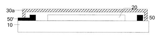
- Step 1012 as illustrated in FIG. 3 b , the display element 20 is packaged to form a lid-like package 30 a covering the display element 20 .
- the first substance 50 is disposed between a joining edge between the package 30 a and the substrate 10 and an edge of the display element 20 , while a part of the first substance 50 ′ remains in the exterior of the like-like package 30 a .
- the amount and shape of the part of the first substance 50 ′ remaining in the exterior of the package 30 will not be limited here.
- the package may be a laminar package 30 b .
- the first substance 50 and a part of the first substance 50 ′ are disposed in an area where the substrate and the package contact each other. The rest of the first substance 50 ′ remains in the exterior of the package 30 b.
- the packaging methods is applicable to the above step 1012 , which will not be elaborated here.
- the first substance is not only included at the joining edge between the package and the substrate and the edge of the display element, but also outside the package.
- the method may further comprise the following step before packaging the display element 20 : applying a glue to a side of the package 30 a or 30 b that faces the display element.
- the package with the glue applied thereto is attached to the display element 20 .
- a glue comprising the first substance 50 is applied to peripheral edges of the side of the package 30 b that faces the display element 20 onto which the package 30 b will be attached, wherein the glue may be applied to positions separated from the edges of the display element 20 by a distance.
- the display element 20 is packaged with the package 30 b with the glue applied thereto to cover the display element 20 .
- the first substance 50 is included in the area between the edge joining the substrate 10 and the package 20 b and the edges of the display element 20 and separated from the display element 20 by a distance.
- the glue comprising the first substance 50 ′ may also be applied to the substrate 10 having the display element 20 disposed thereon around the display element 20 and separated from the display element 20 by a distance. Thereafter, the display element 20 is packaged to form a package 30 a covering the display element 20 .
- the glue comprising the first substance 50 ′ may be kept outside the package 30 a . Alternatively, all the glue is covered by the package.
- a width of the first substance is for example 0.5 mm.
- the first substance 50 , 50 ′ is mixed into the glue.
- the glue is a mixture of the first substance and an adhesive agent with a composition ratio of 4:1 to 9:1.
- the glue when the glue contains the first substance, the first substance is disposed on at least a part of the substrate inside the package by coating, and a width of the first substance is the width of the glue.
- the packaging method according to the embodiment of the invention further comprises:
- Step 102 initiating the first substance to obtain a second substance comprising a product of the thermite reaction.
- the first substance comprising the thermite may be initiated to start the thermite reaction via ignition or thermal effect.
- Initiating the thermite reaction of the substance comprising the thermite via ignition may be the case when the thermite is positioned in the exterior of the package, the thermite outside the package is initiated by ignition.
- an initiator 60 placed outside the package 30 b and in contact with the first substance 50 ′ may be ignited, heat produced by the burning of the initiator 60 first initiates the thermite in the first substance 50 ′ external to the package and then initiates the thermite inside the package to start the thermite reaction.
- the initiator may be concentrated sulfuric acid (98%, H 2 SO 4 ), magnesium powder, or a mixture of hydrogen peroxide (H 2 O 2 ), potassium chlorate (KClO 3 ) and aluminum powder, and so on.
- Initiating the thermite to start the thermite reaction by thermal effect may be the case when the first substance 50 comprising the thermite is completely covered (as illustrated in FIGS. 8 and 9 ) by the package 30 a , 30 b , that is, there is no first substance outside the package 30 a , 30 b .
- the thermite in the first substance 50 inside the package may be initiated to start the thermite reaction by the thermal effect.
- laser heating may be used to initiate the thermite in the first substance 50 between the edge joining the substrate 10 and the package 30 a and the edge of the display element as illustrated in FIG. 8 , and initiate the thermite in the first substance 50 in the contact area between the substrate 10 and the package 30 b as illustrated in FIG. 9 , to start the thermite reaction.
- initiating the thermite to start the thermite reaction is not only applicable to the above situation but also to the case of having the thermite outside the package.
- a preferably initiating method for the thermite outside the package is by way of ignition.
- the second substance comprises the products of the thermite reaction as well as the above substances.
- thermite reaction releases a large amount of heat, which will melt the substrate and the package close to the thermite. Meanwhile, the second substance will be spread into the material of the substrate and/or the package close to the thermite, thereby obtaining the display device 1 as illustrated in FIG. 6 .
- the blockage by the second substance 70 dispersed in the display device 1 makes it impossible for oxygen and water vapor 40 to reach the display element 40 following a direct path. Instead, oxygen and water vapor 40 have to circumvent the dispersed second substance 70 . It thus prolongs the time needed for oxygen and water vapor 40 to reach the display element 20 .
- the first substance further comprises inorganic oxides such as aluminum oxide or silicon dioxide which have excellent hygroscopic property, it can further prevent water vapor from entering the packaged device, thereby increasing the lifetime of the display device 1 .
- An embodiment of the invention also provides a display device comprising: a substrate, a display element disposed on the substrate and a package covering the display element.
- the display device further comprises: a second substance disposed on at least a part of the substrate inside the package, the second substance comprising a product of the thermite reaction.
- the display device 1 comprises: a substrate 10 , a display element 20 disposed on the substrate 10 and a package 30 b covering the display element 20 .
- the display device 1 further comprises a second substance 70 disposed at a region where the substrate 10 contacts the laminar package 30 b , wherein the second substance 70 comprises a product of the thermite reaction.
- the second substance may also be disposed between a joining edge between the lid-like package and the substrate and an edge of the display element and separated from the display element by a distance.
- the second substance 70 is separated from the edge of the display element 10 by at least about 1 mm.
- the second substance may further comprises inorganic oxides, or inorganic nitrides, or a mixture of both, which does not participate in the thermite reaction and is a solid at room temperature.
- inorganic oxides and inorganic nitrides are same to those in the previous embodiment.
- the second substance is dispersed within the material of the substrate and/or the package, when oxygen and water vapor external to the display device get into the interior of the display device via a side of the display device, the blockage by the second substance makes it impossible for oxygen and water vapor to reach the display element following a direct path. Instead, oxygen and water vapor have to circumvent the dispersed second substance. It thus prolongs the time needed for oxygen and water vapor to reach the display element and in turn increasing the lifetime of the display device.
Abstract
A packaging method and a display device are disclosed. The packaging method comprises: packaging a display element on a substrate having the display element disposed thereon to form a package covering the display element, wherein a first substance is disposed on at least a part of the substrate inside the package, the first substance comprising thermite; and initiating the first substance to obtain a second substance comprising a product of the thermite reaction.
Description
This application claims priority from Chinese National Application No. 201210449185.5 filed on Nov. 9, 2012, the contents of which are incorporated herein by reference.
Embodiments of the invention relate to the field of display technologies, more particularly, to a packaging method and a display device.
The Organic Light Emitting Display (OLED) technology, the Electrophoretic Display (EPD) technology and the Organic Photovoltage (OPV) technology all experienced rapid development over the past decade, and both the size of the screen and the display quality are improved significantly.
All the above technologies realize display by using organic and metal materials, which are quite sensitive to oxygen and water vapor. Oxygen and water vapor leaked into the display device will decrease the lifetime of the display device. Therefore, a package isolating oxygen and water vapor is of much importance for the OLED, EPD, OPV technologies.
Currently, the mainstream packages include coating package, thin-film package and so on. With coating package, several layers of organic or inorganic materials are coated or deposited on a display element. As for thin-film package, a thin-film that may effectively isolate oxygen and water vapor is attached to the display element. Lid-like package is one kind of thin-film package, in which the display element is placed in a hermetic space so as to isolate oxygen and water vapor. A final display device is obtained after being packaged with the above methods. However, whatever the package may be, it can only protect the upper part of the display element, while the effect on the interface where the package material bonds to the substrate is quite small, making it easy for oxygen and water vapor to pass and causing device failure. For example, as illustrated in FIG. 1 , a display element 20 and a package 30 are disposed on a substrate 10. Oxygen and water vapor 40 may easily get into the display device 01 from a side of the display device 01, therefore easily reaching the display element 20 and causing erosion to the organic and metal materials in the display element 20 and failing the display element 20.
An embodiment of the invention provides a packaging method and a display device, which can prolong the time needed for oxygen and water vapor to reach a display element, thereby increasing the lifetime of the display device.
In one aspect, the invention provides a packaging method comprising:
packaging a display element on a substrate having the display element disposed thereon to form a package covering the display element, wherein a first substance is disposed on at least a part of the substrate inside the package, the first substance comprising thermite; and
initiating the first substance to obtain a second substance comprising a product of the thermite reaction.
In another aspect, the invention provides a display device comprising a substrate, a display element disposed on the substrate, and a package covering the display element. The display device further comprises a second substance disposed on at least a part of the substrate inside the package, the second substance comprising a product of the thermite reaction.
In order to clearly illustrate the technical solution of the embodiments of the invention, the drawings of the embodiments will be briefly described in the following; it is obvious that the described drawings are only related to some embodiments of the invention and thus are not limitative of the invention.
01, 1—display device, 10—substrate, 20—display element, 30, 30 a, 30 b—package, 40—oxygen and water vapor, 50, 50′—first substance, 60—initiating agent, 70—second substance.
In order to make objects, technical details and advantages of the embodiments of the invention apparent, the technical solutions of the embodiment will be described in a clearly and fully understandable way in connection with the drawings related to the embodiments of the invention. It is obvious that the described embodiments are just a part but not all of the embodiments of the invention. Based on the described embodiments herein, those skilled in the art can obtain other embodiment(s), without any inventive work, which should be within the scope of the invention.
An embodiment of the invention provides a packaging method as illustrated in FIG. 2 , which comprises:
Step 101: package a display element on a substrate having the display element disposed thereon to form a package covering the display element, wherein a first substance is disposed on at least a part of the substrate inside the package, the first substance contains thermite.
For example, when the package is a lid-like package, the first substance may be disposed between a joining edge between the package and the substrate and an edge of the display element (as shown in FIG. 8 ). When the package is a lamina, the first substance is positioned in an area where the laminar package contacts the substrate (as illustrated in FIG. 9 ). Furthermore, the first substance is separated from an edge of the display element; that is, there is a distance between the first substance and the edge of the display element. Herein, the “distance” is set according to an amount of the thermite in the first substance and as not influencing the display element, which will not be limited here. Moreover, a shape of the first substance on the substrate will not be limited in the embodiment of the invention. Preferably, a part of the first substance may extend to the exterior of the package (as shown in FIG. 10 ), such that the first substance is exposed to facilitate the initiation of the thermite in the first substance.
As an example, the method may further comprise: disposing the first substance on the substrate around the display element, before packaging the display element (as shown in FIG. 11 ).
As another example, the method may further comprise: applying the first substance to a side of the package that faces the display element, before packaging the display element (as shown in FIG. 12 ).
The thermite in the first substance may be a mixture of aluminium powder and Iron (III) oxide (Fe2O3), or a mixture of aluminium powder and Iron (II, III) oxide (Fe3O4), or a mixture of aluminium powder and Manganese (III) oxide (Mn2O3).
As the thermal effect of the thermite is quite intense, the first substance may further comprise inorganic oxides, or inorganic nitrides, or a mixture of both, which does not participate in the thermite reaction and is a solid at room temperature, so as to reduce the intensity of the thermite reaction and to insulate oxygen and water vapor.
The inorganic oxide may for example be aluminum oxide powder (Al2O3), silicon dioxide powder (SiO2), iron (III) oxide powder (Fe2O3), iron (II, III) oxide (Fe3O4), manganese(IV) oxide (MnO2), titanium dioxide (TiO2), zirconium dioxide (ZrO2) or a mixture of at least two of the above substances. The inorganic nitride may be for example silicon nitride. The first substance may further comprise a mixture of any of the above inorganic oxides and inorganic nitrides.
The substrate is for example made of glass, metal, plastic or a combination of two or more of the above. The package is for example made of plastic, glass, composite plastic or combination of two or more of the above.
Please note that the display element according to the embodiment of the invention refers to the element for realizing the display function. Furthermore, the display element may realize the display function together with the substrate. In this case, the substrate is for example an Indium Tin Oxides (ITO) glass substrate.
Specific examples of step 101 are described in the following.
As an example, step 101 may comprise:
Step 1011: as illustrate in FIG. 3a , the first substance 50 and 50′ is disposed on the substrate 10 having the display element 20 disposed thereon around the display element 20 and separated by a distance from edges of the display element 20. Please note that shapes of the first substance 50 and 50′ are for illustrative purpose only and may be decided according to practical need in real applications.
Step 1012: as illustrated in FIG. 3b , the display element 20 is packaged to form a lid-like package 30 a covering the display element 20. At this point, the first substance 50 is disposed between a joining edge between the package 30 a and the substrate 10 and an edge of the display element 20, while a part of the first substance 50′ remains in the exterior of the like-like package 30 a. The amount and shape of the part of the first substance 50′ remaining in the exterior of the package 30 will not be limited here.
Alternatively, the package may be a laminar package 30 b. As illustrated in FIG. 4 , the first substance 50 and a part of the first substance 50′ are disposed in an area where the substrate and the package contact each other. The rest of the first substance 50′ remains in the exterior of the package 30 b.
Either of the packaging methods is applicable to the above step 1012, which will not be elaborated here. With the above step, the first substance is not only included at the joining edge between the package and the substrate and the edge of the display element, but also outside the package. By means of the methods, it is convenient to initiate the thermite in the first substance outside the package via an initiator, thereby initiating the thermite inside the package.
Optionally, the method may further comprise the following step before packaging the display element 20: applying a glue to a side of the package 30 a or 30 b that faces the display element. In this case, the package with the glue applied thereto is attached to the display element 20.
For example, as illustrated in FIG. 12 , a glue comprising the first substance 50 is applied to peripheral edges of the side of the package 30 b that faces the display element 20 onto which the package 30 b will be attached, wherein the glue may be applied to positions separated from the edges of the display element 20 by a distance. Next, the display element 20 is packaged with the package 30 b with the glue applied thereto to cover the display element 20. By this means, the first substance 50 is included in the area between the edge joining the substrate 10 and the package 20 b and the edges of the display element 20 and separated from the display element 20 by a distance.
Furthermore, as illustrated in FIG. 11 , the glue comprising the first substance 50′ may also be applied to the substrate 10 having the display element 20 disposed thereon around the display element 20 and separated from the display element 20 by a distance. Thereafter, the display element 20 is packaged to form a package 30 a covering the display element 20. Herein, during the packaging, at least a part of the glue comprising the first substance 50′ may be kept outside the package 30 a. Alternatively, all the glue is covered by the package.
In consideration of the size of the display device, a width of the first substance is for example 0.5 mm.
In the example, the first substance 50, 50′ is mixed into the glue. As an example, the glue is a mixture of the first substance and an adhesive agent with a composition ratio of 4:1 to 9:1.
Herein, when the glue contains the first substance, the first substance is disposed on at least a part of the substrate inside the package by coating, and a width of the first substance is the width of the glue.
Still referring to FIG. 2 , the packaging method according to the embodiment of the invention further comprises:
Step 102: initiating the first substance to obtain a second substance comprising a product of the thermite reaction.
For example, the first substance comprising the thermite may be initiated to start the thermite reaction via ignition or thermal effect.
Initiating the thermite reaction of the substance comprising the thermite via ignition may be the case when the thermite is positioned in the exterior of the package, the thermite outside the package is initiated by ignition.
For example, as illustrated in FIG. 5 , an initiator 60 placed outside the package 30 b and in contact with the first substance 50′ may be ignited, heat produced by the burning of the initiator 60 first initiates the thermite in the first substance 50′ external to the package and then initiates the thermite inside the package to start the thermite reaction. The initiator may be concentrated sulfuric acid (98%, H2SO4), magnesium powder, or a mixture of hydrogen peroxide (H2O2), potassium chlorate (KClO3) and aluminum powder, and so on.
Initiating the thermite to start the thermite reaction by thermal effect may be the case when the first substance 50 comprising the thermite is completely covered (as illustrated in FIGS. 8 and 9 ) by the package 30 a, 30 b, that is, there is no first substance outside the package 30 a, 30 b. In this case, the thermite in the first substance 50 inside the package may be initiated to start the thermite reaction by the thermal effect.
As an example, laser heating may be used to initiate the thermite in the first substance 50 between the edge joining the substrate 10 and the package 30 a and the edge of the display element as illustrated in FIG. 8 , and initiate the thermite in the first substance 50 in the contact area between the substrate 10 and the package 30 b as illustrated in FIG. 9 , to start the thermite reaction.
Please note that initiating the thermite to start the thermite reaction is not only applicable to the above situation but also to the case of having the thermite outside the package. However, a preferably initiating method for the thermite outside the package is by way of ignition.
Moreover, in the case that the first substance further comprises inorganic oxides, inorganic nitrides or a mixture of both which does not participate in the thermite reaction and is a solid at room temperature, the second substance comprises the products of the thermite reaction as well as the above substances.
In the above step 102, the thermite reaction releases a large amount of heat, which will melt the substrate and the package close to the thermite. Meanwhile, the second substance will be spread into the material of the substrate and/or the package close to the thermite, thereby obtaining the display device 1 as illustrated in FIG. 6 .
When oxygen and water vapor 40 external to the display device 1 get into the interior of the display device 1 via a side, that is, an interface between the package 30 b and the substrate 10, of the display device 1, the blockage by the second substance 70 dispersed in the display device 1 makes it impossible for oxygen and water vapor 40 to reach the display element 40 following a direct path. Instead, oxygen and water vapor 40 have to circumvent the dispersed second substance 70. It thus prolongs the time needed for oxygen and water vapor 40 to reach the display element 20. If the first substance further comprises inorganic oxides such as aluminum oxide or silicon dioxide which have excellent hygroscopic property, it can further prevent water vapor from entering the packaged device, thereby increasing the lifetime of the display device 1.
An embodiment of the invention also provides a display device comprising: a substrate, a display element disposed on the substrate and a package covering the display element. The display device further comprises: a second substance disposed on at least a part of the substrate inside the package, the second substance comprising a product of the thermite reaction.
For example, as illustrated in FIG. 7 , the display device 1 comprises: a substrate 10, a display element 20 disposed on the substrate 10 and a package 30 b covering the display element 20. The display device 1 further comprises a second substance 70 disposed at a region where the substrate 10 contacts the laminar package 30 b, wherein the second substance 70 comprises a product of the thermite reaction.
Alternatively, the second substance may also be disposed between a joining edge between the lid-like package and the substrate and an edge of the display element and separated from the display element by a distance.
To prevent the second substance 70 from affecting the display and other functions of the display device 1, the second substance 70 is separated from the edge of the display element 10 by at least about 1 mm.
The second substance may further comprises inorganic oxides, or inorganic nitrides, or a mixture of both, which does not participate in the thermite reaction and is a solid at room temperature. Examples of the inorganic oxides and inorganic nitrides are same to those in the previous embodiment.
In the display device according to the embodiment of the invention, as the second substance is dispersed within the material of the substrate and/or the package, when oxygen and water vapor external to the display device get into the interior of the display device via a side of the display device, the blockage by the second substance makes it impossible for oxygen and water vapor to reach the display element following a direct path. Instead, oxygen and water vapor have to circumvent the dispersed second substance. It thus prolongs the time needed for oxygen and water vapor to reach the display element and in turn increasing the lifetime of the display device.
What are described above is related to the illustrative embodiments of the disclosure only and not limitative to the scope of the disclosure; the scopes of the disclosure are defined by the accompanying claims.
Claims (14)
1. A packaging method, comprising:
packaging a display element on a substrate having the display element disposed thereon to form a package covering the display element, wherein a first substance is disposed on at least a part of the substrate inside the package, the first substance comprising thermite; and
initiating the first substance to obtain a second substance comprising a product of the thermite reaction,
wherein the package has a lid shape and is in direct contact with the substrate to form a contact area, and the first substance is disposed in a gap between the contact area and the display element.
2. The method of claim 1 , wherein the first substance is separated from the display element.
3. The method of claim 2 , wherein the first substance is disposed between a joining edge between the substrate and the package and an edge of the display element.
4. The method of claim 2 , wherein the first substance is disposed in an area where the substrate contacts the package.
5. The method of claim 1 , wherein the first substance is disposed between a joining edge between the substrate and the package and an edge of the display element.
6. The method of claim 1 , wherein the first substance is disposed in an area where the substrate contacts the package.
7. The method of claim 1 , wherein the first substance is included in a glue.
8. The method of claim 1 , wherein before packaging the display element, the method further comprises:
applying the first substance to the substrate around the display element.
9. The method of claim 1 , wherein before packaging the display element, the method further comprises:
applying the first substance to a side of the package that faces the display element.
10. The method of claim 9 , wherein the method further comprises attaching the package with the first substance applied thereto to the display element.
11. The method of claim 1 , wherein a width of the first substance is 0.5 mm.
12. The method of claim 1 , wherein the first substance further comprises inorganic oxides, inorganic nitrides or a mixture of both.
13. The method of claim 1 , wherein initiating the first substance comprises:
initiating the thermite to start the thermite reaction via ignition or thermal effect.
14. The method of claim 1 , wherein a part of the first substance extends to the exterior of the package and becomes exposed.
Priority Applications (1)
| Application Number | Priority Date | Filing Date | Title |
|---|---|---|---|
| US15/690,943 US10205134B2 (en) | 2012-11-09 | 2017-08-30 | Packaging method and display device |
Applications Claiming Priority (3)
| Application Number | Priority Date | Filing Date | Title |
|---|---|---|---|
| CN201210449185.5 | 2012-11-09 | ||
| CN201210449185.5A CN102945927B (en) | 2012-11-09 | 2012-11-09 | Packaging method and display device |
| CN201210449185 | 2012-11-09 |
Related Child Applications (1)
| Application Number | Title | Priority Date | Filing Date |
|---|---|---|---|
| US15/690,943 Continuation US10205134B2 (en) | 2012-11-09 | 2017-08-30 | Packaging method and display device |
Publications (2)
| Publication Number | Publication Date |
|---|---|
| US20140134381A1 US20140134381A1 (en) | 2014-05-15 |
| US9831470B2 true US9831470B2 (en) | 2017-11-28 |
Family
ID=47728850
Family Applications (2)
| Application Number | Title | Priority Date | Filing Date |
|---|---|---|---|
| US14/073,458 Active 2036-04-03 US9831470B2 (en) | 2012-11-09 | 2013-11-06 | Packaging method and display device |
| US15/690,943 Active US10205134B2 (en) | 2012-11-09 | 2017-08-30 | Packaging method and display device |
Family Applications After (1)
| Application Number | Title | Priority Date | Filing Date |
|---|---|---|---|
| US15/690,943 Active US10205134B2 (en) | 2012-11-09 | 2017-08-30 | Packaging method and display device |
Country Status (3)
| Country | Link |
|---|---|
| US (2) | US9831470B2 (en) |
| EP (1) | EP2731158B1 (en) |
| CN (1) | CN102945927B (en) |
Families Citing this family (3)
| Publication number | Priority date | Publication date | Assignee | Title |
|---|---|---|---|---|
| CN106960916A (en) * | 2017-05-12 | 2017-07-18 | 深圳市华星光电技术有限公司 | A kind of thin-film packing structure of OLED and preparation method thereof |
| CN110491840B (en) * | 2019-08-23 | 2021-03-02 | 广东盈骅新材料科技有限公司 | Packaging substrate with good thermal expansion performance |
| CN113157131B (en) * | 2021-04-12 | 2023-12-29 | 深圳市华星光电半导体显示技术有限公司 | Touch display device and manufacturing method thereof |
Citations (5)
| Publication number | Priority date | Publication date | Assignee | Title |
|---|---|---|---|---|
| US20070290615A1 (en) * | 2006-06-16 | 2007-12-20 | Lg.Philips Lcd Co., Ltd. | Display panel assembly and method of manufacturing the same |
| WO2011012420A1 (en) * | 2009-07-30 | 2011-02-03 | Osram Opto Semiconductors Gmbh | Organic component and method for the production thereof |
| US20110127314A1 (en) | 2009-11-30 | 2011-06-02 | Infineon Technologies Ag | Bonding material with exothermically reactive heterostructures |
| WO2011148990A1 (en) * | 2010-05-26 | 2011-12-01 | 旭硝子株式会社 | Transparent surface material having adhesive layer, display device, and manufacturing method for same |
| CN102701591A (en) | 2012-06-07 | 2012-10-03 | 上海大学 | Laser packaged glass powder sealing material for photoelectric device packaging |
Family Cites Families (2)
| Publication number | Priority date | Publication date | Assignee | Title |
|---|---|---|---|---|
| CN101405321A (en) * | 2006-03-30 | 2009-04-08 | 国家淀粉及化学投资控股公司 | Hot curable epoxy-amine anti-seepage fluid sealant |
| TWI406017B (en) | 2010-11-26 | 2013-08-21 | Au Optronics Corp | Lcd apparatus, lcd panel, and color filter substrate thereof |
-
2012
- 2012-11-09 CN CN201210449185.5A patent/CN102945927B/en active Active
-
2013
- 2013-11-06 EP EP13191737.9A patent/EP2731158B1/en active Active
- 2013-11-06 US US14/073,458 patent/US9831470B2/en active Active
-
2017
- 2017-08-30 US US15/690,943 patent/US10205134B2/en active Active
Patent Citations (8)
| Publication number | Priority date | Publication date | Assignee | Title |
|---|---|---|---|---|
| US20070290615A1 (en) * | 2006-06-16 | 2007-12-20 | Lg.Philips Lcd Co., Ltd. | Display panel assembly and method of manufacturing the same |
| WO2011012420A1 (en) * | 2009-07-30 | 2011-02-03 | Osram Opto Semiconductors Gmbh | Organic component and method for the production thereof |
| US20120256170A1 (en) * | 2009-07-30 | 2012-10-11 | Marc Philippens | Organic Component and Method for the Production Thereof |
| US20110127314A1 (en) | 2009-11-30 | 2011-06-02 | Infineon Technologies Ag | Bonding material with exothermically reactive heterostructures |
| WO2011148990A1 (en) * | 2010-05-26 | 2011-12-01 | 旭硝子株式会社 | Transparent surface material having adhesive layer, display device, and manufacturing method for same |
| US20130029075A1 (en) * | 2010-05-26 | 2013-01-31 | Asahi Glass Company, Limited | Transparent plate having adhesive layer, display device and processes for their production |
| JPWO2011148990A1 (en) * | 2010-05-26 | 2013-07-25 | 旭硝子株式会社 | Transparent surface material with adhesive layer, display device and manufacturing method thereof |
| CN102701591A (en) | 2012-06-07 | 2012-10-03 | 上海大学 | Laser packaged glass powder sealing material for photoelectric device packaging |
Non-Patent Citations (6)
| Title |
|---|
| English language Abstract of CN102062971A (listed above under Foreign Patent Documents); 1 pg. |
| English language translation of First Office Action of the State Intellectual Property Office of the People's Republic of China, for Chinese Application No. 201210449185.5, dated Sep. 22, 2014, with Search Report-5 pgs. |
| English language translation of First Office Action of the State Intellectual Property Office of the People's Republic of China, for Chinese Application No. 201210449185.5, dated Sep. 22, 2014, with Search Report—5 pgs. |
| First Office Action of the State Intellectual Property Office of the People's Republic of China, for Chinese Application No. 201210449185.5, dated Sep. 22, 2014, with Search Report-7 pgs. |
| First Office Action of the State Intellectual Property Office of the People's Republic of China, for Chinese Application No. 201210449185.5, dated Sep. 22, 2014, with Search Report—7 pgs. |
| The Extended European Search Report date Sep. 29, 2017; Appln. 13191737.9-1555/2731158. |
Also Published As
| Publication number | Publication date |
|---|---|
| CN102945927A (en) | 2013-02-27 |
| US20170365823A1 (en) | 2017-12-21 |
| EP2731158B1 (en) | 2022-05-18 |
| US20140134381A1 (en) | 2014-05-15 |
| EP2731158A2 (en) | 2014-05-14 |
| EP2731158A3 (en) | 2017-11-01 |
| US10205134B2 (en) | 2019-02-12 |
| CN102945927B (en) | 2015-01-28 |
Similar Documents
| Publication | Publication Date | Title |
|---|---|---|
| US10205134B2 (en) | Packaging method and display device | |
| CN104505466B (en) | OLED encapsulating structure and method for packing thereof | |
| CN105097885B (en) | Oled panel and its packaging method, display device | |
| US8957410B2 (en) | Organic light-emitting diode package structure and method for forming the same | |
| US10038162B2 (en) | OLED package structure and packaging method | |
| TWI515937B (en) | Package structure of organic optic-electro device and method for packaging thereof | |
| US20090009046A1 (en) | Light emitting display and method of manufacturing the same | |
| US9490448B2 (en) | OLED device packaging method and OLED device packaged with same | |
| US20160343979A1 (en) | Oled (organic light emitting diode) packaging method and oled package structure | |
| US10892439B2 (en) | Display panel having filler layer and heat dissipation layer and packaging method thereof, and display apparatus | |
| JP2010225569A (en) | Organic electroluminescent display device | |
| CN104124268A (en) | Organic light emitting diode (OLED) display panel and manufacture method thereof | |
| CN103325958A (en) | Organic light-emitting device packaging cover plate, organic light-emitting device and displayer | |
| WO2015018107A1 (en) | Oled encapsulation structure and encapsulation method | |
| WO2014035954A3 (en) | Antimony-free glass, antimony-free frit and a glass package that is hermetically sealed with the frit | |
| MY193117A (en) | Fluidic devices and methods of manufacturing the same | |
| KR20230117076A (en) | Organic light emitting display panel and method of manufacturing the same | |
| WO2009003130A3 (en) | Gasketless low-temperature hermetic sealing with solder | |
| TWI414821B (en) | E-ink display device and manufacturing method thereof | |
| JP2010026307A (en) | Liquid crystal display element and method of manufacturing the same | |
| JP2005141199A5 (en) | ||
| CN105549250B (en) | A kind of array base palte, display panel and its corresponding preparation method and display device | |
| WO2004082337A1 (en) | Display panel and process for producing the same | |
| JP2001210465A (en) | Display panel device and manufacturing method of the same | |
| WO2019134192A1 (en) | Oled panel and manufacturing method therefor |
Legal Events
| Date | Code | Title | Description |
|---|---|---|---|
| AS | Assignment |
Owner name: BOE TECHNOLOGY GROUP CO., LTD., CHINA Free format text: ASSIGNMENT OF ASSIGNORS INTEREST;ASSIGNOR:ZHOU, WEIFENG;REEL/FRAME:031556/0307 Effective date: 20131106 |
|
| STCF | Information on status: patent grant |
Free format text: PATENTED CASE |
|
| MAFP | Maintenance fee payment |
Free format text: PAYMENT OF MAINTENANCE FEE, 4TH YEAR, LARGE ENTITY (ORIGINAL EVENT CODE: M1551); ENTITY STATUS OF PATENT OWNER: LARGE ENTITY Year of fee payment: 4 |