US9823130B2 - Multi-angle spectral imaging measurement method and apparatus - Google Patents
Multi-angle spectral imaging measurement method and apparatus Download PDFInfo
- Publication number
- US9823130B2 US9823130B2 US15/265,816 US201615265816A US9823130B2 US 9823130 B2 US9823130 B2 US 9823130B2 US 201615265816 A US201615265816 A US 201615265816A US 9823130 B2 US9823130 B2 US 9823130B2
- Authority
- US
- United States
- Prior art keywords
- measurement
- sample surface
- spectral
- image
- angle
- Prior art date
- Legal status (The legal status is an assumption and is not a legal conclusion. Google has not performed a legal analysis and makes no representation as to the accuracy of the status listed.)
- Expired - Fee Related
Links
Images


Classifications
-
- G—PHYSICS
- G01—MEASURING; TESTING
- G01J—MEASUREMENT OF INTENSITY, VELOCITY, SPECTRAL CONTENT, POLARISATION, PHASE OR PULSE CHARACTERISTICS OF INFRARED, VISIBLE OR ULTRAVIOLET LIGHT; COLORIMETRY; RADIATION PYROMETRY
- G01J3/00—Spectrometry; Spectrophotometry; Monochromators; Measuring colours
- G01J3/28—Investigating the spectrum
- G01J3/2823—Imaging spectrometer
-
- G—PHYSICS
- G01—MEASURING; TESTING
- G01J—MEASUREMENT OF INTENSITY, VELOCITY, SPECTRAL CONTENT, POLARISATION, PHASE OR PULSE CHARACTERISTICS OF INFRARED, VISIBLE OR ULTRAVIOLET LIGHT; COLORIMETRY; RADIATION PYROMETRY
- G01J3/00—Spectrometry; Spectrophotometry; Monochromators; Measuring colours
- G01J3/02—Details
- G01J3/0205—Optical elements not provided otherwise, e.g. optical manifolds, diffusers, windows
- G01J3/0208—Optical elements not provided otherwise, e.g. optical manifolds, diffusers, windows using focussing or collimating elements, e.g. lenses or mirrors; performing aberration correction
-
- G—PHYSICS
- G01—MEASURING; TESTING
- G01J—MEASUREMENT OF INTENSITY, VELOCITY, SPECTRAL CONTENT, POLARISATION, PHASE OR PULSE CHARACTERISTICS OF INFRARED, VISIBLE OR ULTRAVIOLET LIGHT; COLORIMETRY; RADIATION PYROMETRY
- G01J3/00—Spectrometry; Spectrophotometry; Monochromators; Measuring colours
- G01J3/02—Details
- G01J3/0264—Electrical interface; User interface
-
- G—PHYSICS
- G01—MEASURING; TESTING
- G01J—MEASUREMENT OF INTENSITY, VELOCITY, SPECTRAL CONTENT, POLARISATION, PHASE OR PULSE CHARACTERISTICS OF INFRARED, VISIBLE OR ULTRAVIOLET LIGHT; COLORIMETRY; RADIATION PYROMETRY
- G01J3/00—Spectrometry; Spectrophotometry; Monochromators; Measuring colours
- G01J3/02—Details
- G01J3/0297—Constructional arrangements for removing other types of optical noise or for performing calibration
-
- G—PHYSICS
- G01—MEASURING; TESTING
- G01J—MEASUREMENT OF INTENSITY, VELOCITY, SPECTRAL CONTENT, POLARISATION, PHASE OR PULSE CHARACTERISTICS OF INFRARED, VISIBLE OR ULTRAVIOLET LIGHT; COLORIMETRY; RADIATION PYROMETRY
- G01J3/00—Spectrometry; Spectrophotometry; Monochromators; Measuring colours
- G01J3/12—Generating the spectrum; Monochromators
- G01J3/1256—Generating the spectrum; Monochromators using acousto-optic tunable filter
-
- G—PHYSICS
- G01—MEASURING; TESTING
- G01J—MEASUREMENT OF INTENSITY, VELOCITY, SPECTRAL CONTENT, POLARISATION, PHASE OR PULSE CHARACTERISTICS OF INFRARED, VISIBLE OR ULTRAVIOLET LIGHT; COLORIMETRY; RADIATION PYROMETRY
- G01J3/00—Spectrometry; Spectrophotometry; Monochromators; Measuring colours
- G01J3/28—Investigating the spectrum
- G01J3/42—Absorption spectrometry; Double beam spectrometry; Flicker spectrometry; Reflection spectrometry
-
- G—PHYSICS
- G01—MEASURING; TESTING
- G01J—MEASUREMENT OF INTENSITY, VELOCITY, SPECTRAL CONTENT, POLARISATION, PHASE OR PULSE CHARACTERISTICS OF INFRARED, VISIBLE OR ULTRAVIOLET LIGHT; COLORIMETRY; RADIATION PYROMETRY
- G01J3/00—Spectrometry; Spectrophotometry; Monochromators; Measuring colours
- G01J3/46—Measurement of colour; Colour measuring devices, e.g. colorimeters
- G01J3/463—Colour matching
-
- G—PHYSICS
- G01—MEASURING; TESTING
- G01J—MEASUREMENT OF INTENSITY, VELOCITY, SPECTRAL CONTENT, POLARISATION, PHASE OR PULSE CHARACTERISTICS OF INFRARED, VISIBLE OR ULTRAVIOLET LIGHT; COLORIMETRY; RADIATION PYROMETRY
- G01J3/00—Spectrometry; Spectrophotometry; Monochromators; Measuring colours
- G01J3/46—Measurement of colour; Colour measuring devices, e.g. colorimeters
- G01J3/50—Measurement of colour; Colour measuring devices, e.g. colorimeters using electric radiation detectors
- G01J3/501—Colorimeters using spectrally-selective light sources, e.g. LEDs
-
- G—PHYSICS
- G01—MEASURING; TESTING
- G01J—MEASUREMENT OF INTENSITY, VELOCITY, SPECTRAL CONTENT, POLARISATION, PHASE OR PULSE CHARACTERISTICS OF INFRARED, VISIBLE OR ULTRAVIOLET LIGHT; COLORIMETRY; RADIATION PYROMETRY
- G01J3/00—Spectrometry; Spectrophotometry; Monochromators; Measuring colours
- G01J3/46—Measurement of colour; Colour measuring devices, e.g. colorimeters
- G01J3/50—Measurement of colour; Colour measuring devices, e.g. colorimeters using electric radiation detectors
- G01J3/502—Measurement of colour; Colour measuring devices, e.g. colorimeters using electric radiation detectors using a dispersive element, e.g. grating, prism
-
- G—PHYSICS
- G01—MEASURING; TESTING
- G01J—MEASUREMENT OF INTENSITY, VELOCITY, SPECTRAL CONTENT, POLARISATION, PHASE OR PULSE CHARACTERISTICS OF INFRARED, VISIBLE OR ULTRAVIOLET LIGHT; COLORIMETRY; RADIATION PYROMETRY
- G01J3/00—Spectrometry; Spectrophotometry; Monochromators; Measuring colours
- G01J3/46—Measurement of colour; Colour measuring devices, e.g. colorimeters
- G01J3/50—Measurement of colour; Colour measuring devices, e.g. colorimeters using electric radiation detectors
- G01J3/504—Goniometric colour measurements, for example measurements of metallic or flake based paints
-
- G—PHYSICS
- G01—MEASURING; TESTING
- G01J—MEASUREMENT OF INTENSITY, VELOCITY, SPECTRAL CONTENT, POLARISATION, PHASE OR PULSE CHARACTERISTICS OF INFRARED, VISIBLE OR ULTRAVIOLET LIGHT; COLORIMETRY; RADIATION PYROMETRY
- G01J3/00—Spectrometry; Spectrophotometry; Monochromators; Measuring colours
- G01J3/46—Measurement of colour; Colour measuring devices, e.g. colorimeters
- G01J3/52—Measurement of colour; Colour measuring devices, e.g. colorimeters using colour charts
- G01J3/524—Calibration of colorimeters
-
- G—PHYSICS
- G01—MEASURING; TESTING
- G01N—INVESTIGATING OR ANALYSING MATERIALS BY DETERMINING THEIR CHEMICAL OR PHYSICAL PROPERTIES
- G01N21/00—Investigating or analysing materials by the use of optical means, i.e. using sub-millimetre waves, infrared, visible or ultraviolet light
- G01N21/17—Systems in which incident light is modified in accordance with the properties of the material investigated
- G01N21/25—Colour; Spectral properties, i.e. comparison of effect of material on the light at two or more different wavelengths or wavelength bands
- G01N21/255—Details, e.g. use of specially adapted sources, lighting or optical systems
-
- G—PHYSICS
- G01—MEASURING; TESTING
- G01N—INVESTIGATING OR ANALYSING MATERIALS BY DETERMINING THEIR CHEMICAL OR PHYSICAL PROPERTIES
- G01N21/00—Investigating or analysing materials by the use of optical means, i.e. using sub-millimetre waves, infrared, visible or ultraviolet light
- G01N21/17—Systems in which incident light is modified in accordance with the properties of the material investigated
- G01N21/25—Colour; Spectral properties, i.e. comparison of effect of material on the light at two or more different wavelengths or wavelength bands
- G01N21/27—Colour; Spectral properties, i.e. comparison of effect of material on the light at two or more different wavelengths or wavelength bands using photo-electric detection ; circuits for computing concentration
- G01N21/274—Calibration, base line adjustment, drift correction
- G01N21/276—Calibration, base line adjustment, drift correction with alternation of sample and standard in optical path
-
- G—PHYSICS
- G01—MEASURING; TESTING
- G01N—INVESTIGATING OR ANALYSING MATERIALS BY DETERMINING THEIR CHEMICAL OR PHYSICAL PROPERTIES
- G01N21/00—Investigating or analysing materials by the use of optical means, i.e. using sub-millimetre waves, infrared, visible or ultraviolet light
- G01N21/17—Systems in which incident light is modified in accordance with the properties of the material investigated
- G01N21/55—Specular reflectivity
- G01N21/57—Measuring gloss
-
- G—PHYSICS
- G01—MEASURING; TESTING
- G01N—INVESTIGATING OR ANALYSING MATERIALS BY DETERMINING THEIR CHEMICAL OR PHYSICAL PROPERTIES
- G01N21/00—Investigating or analysing materials by the use of optical means, i.e. using sub-millimetre waves, infrared, visible or ultraviolet light
- G01N21/84—Systems specially adapted for particular applications
- G01N21/8422—Investigating thin films, e.g. matrix isolation method
-
- G—PHYSICS
- G01—MEASURING; TESTING
- G01J—MEASUREMENT OF INTENSITY, VELOCITY, SPECTRAL CONTENT, POLARISATION, PHASE OR PULSE CHARACTERISTICS OF INFRARED, VISIBLE OR ULTRAVIOLET LIGHT; COLORIMETRY; RADIATION PYROMETRY
- G01J3/00—Spectrometry; Spectrophotometry; Monochromators; Measuring colours
- G01J3/12—Generating the spectrum; Monochromators
- G01J2003/1226—Interference filters
-
- G—PHYSICS
- G01—MEASURING; TESTING
- G01J—MEASUREMENT OF INTENSITY, VELOCITY, SPECTRAL CONTENT, POLARISATION, PHASE OR PULSE CHARACTERISTICS OF INFRARED, VISIBLE OR ULTRAVIOLET LIGHT; COLORIMETRY; RADIATION PYROMETRY
- G01J3/00—Spectrometry; Spectrophotometry; Monochromators; Measuring colours
- G01J3/28—Investigating the spectrum
- G01J3/2823—Imaging spectrometer
- G01J2003/2826—Multispectral imaging, e.g. filter imaging
-
- G—PHYSICS
- G01—MEASURING; TESTING
- G01N—INVESTIGATING OR ANALYSING MATERIALS BY DETERMINING THEIR CHEMICAL OR PHYSICAL PROPERTIES
- G01N2201/00—Features of devices classified in G01N21/00
- G01N2201/06—Illumination; Optics
- G01N2201/061—Sources
Definitions
- the present invention relates to any fields, such as paint, coating, textile, printing, and plastic, in which colors of surfaces of objects are measured and to a multi-angle spectral imaging measurement method and apparatus used in measurement and evaluation, and manufacturing based on the measurement and evaluation.
- Design aesthetic is one of the very important added-values of industrial products today. Accordingly, there are many products that have various kinds of texture and surface structures.
- the outer coating materials of automobiles contain various kinds of effect materials and accordingly their surfaces have extremely minute glitter reflective and granular texture.
- colors significantly change according to variations in combinations of effect materials, pigments and other materials, layer structures of coating, and geometrical conditions of lighting and observation directions.
- the advent of interference effect materials in recent years has added variety to colors and texture.
- the surface structures of other products such as interior materials, furniture, buildings, electric appliances, electronic devices, cosmetics, and packages have become complex regardless of inclusion of effect materials.
- the colors and texture of products change in various ways depending on texture and optical geometrical conditions.
- wood products and textile products as well as coated products exhibit color changes and texture changes depending on optical geometrical conditions. Not only industrial products, but also skin and biological matters exhibit color changes and texture changes depending on optical geometrical conditions.
- Patent document 1 discloses a technique that uses light dispersed by a prism or a diffraction grating to acquire spectral information that differs among parts of an image.
- Patent document 2 discloses a technique relating to a multi-angle spectral imaging apparatus including a rotary illumination light source and a multispectral camera.
- Patent document 3 discloses a technique in which a white reference surface is provided around an entire sample surface in order to correct time fluctuations in an illumination light source.
- Patent document 4 discloses a technique that uses a lighting device including a plurality of monochromatic LEDs that are arranged in a row and capable of emitting light rays of different colors to illuminate a sample surface and take an image when multi-angle spectral measurement is performed.
- Patent document 5 discloses a technique relating to a spectral measurement system including a spectrometer that measures a first spectrum of a subject under ultraviolet illumination light and a second spectrum of the subject under visible illumination light.
- Patent document 6 discloses a technique relating to a color measurement apparatus that measures spectral characteristics of a sample and performs computations.
- Patent document 1 Japanese Patent No. 3933581
- Patent document 2 Japanese Patent Laid-Open No. 2005-181038
- Patent document 3 Japanese Examined Patent Publication No. 60-041731
- Patent document 4 Japanese Patent Laid-Open No. 2004-226262
- Patent document 5 Japanese Patent Laid-Open No. 2003-337067
- Patent document 6 Japanese Patent Laid-Open No. 2007-333726
- Patent document 1 provides a method for acquiring spectral information that differs among parts of an image.
- the spectral information differs only among pixels and spectral information with different wavelengths or the like for different pixels cannot be acquired at all of the pixels.
- means for correcting changes in the amount of light and changes in exposure time during measurement is not configured. Accordingly, it is difficult for the technique to provide high-precision measurement that is practical in manufacturing coating materials or product manufacturing that involves coating.
- the lighting device illuminates from only one angular position that is greater than 40 degrees, the field angle of a recording device needs to be wide, causing distortion near the rim of an imaging lens which is generally used in the recording device.
- the technique disclosed in Patent document 2 relates to a multi-angle spectral imaging apparatus including an illumination light source and a multispectral camera.
- the illumination light source disclosed is a light source that rotates illumination from one position or one illuminant, or a configuration in which a sample is rotated. This makes accurate measurement difficult and requires a mechanism for causing rotation, which adds to complexity to the mechanism of the imaging apparatus.
- Patent document 3 applies light from a light source to light reflected from an object to be measured and to background light, receives light rays are received at a light receiver, then compares both light rays with each other but does not acquire spectral information by taking an image of applied light.
- the technique disclosed in Patent document 4 uses two fixed lighting devices for measurement.
- a problem with the technique is that since each of the lighting devices has monochrome LEDs that are arranged in a row and emit light rays of different colors and the LEDs are turned on and off independently of each other, the different light-emitting LEDs emit light to an object to be measured at different angles and information acquired with an image pickup device differs accordingly.
- Patent document 5 provides a plurality of light emitting parts that have a plurality of different spectral energy distributions.
- the technique has a problem that since the light emitting parts are provided separately, the different light emitting parts emit light to an object to be measured at different angles and information acquired with a spectrometer differs accordingly.
- Patent document 6 only performs image computations based on information acquired with a spectrometer.
- image measurement that is capable of multi-angle measurement in which optical geometrical conditions based on lighting and observation directions can be changed in a wide color gamut is required and effective. Furthermore, image analysis calculations for quantifying features of measured spectral imaging information are required.
- an object of the present invention is to provide a method and an apparatus that efficiently measure information such as multi-angle spectral information on each pixel of a surface of an object in a short time and, more specifically, to implement a more accurate and practical multi-angle spectral imaging measurement method and apparatus.
- Another object is to implement a multi-angle spectral imaging measurement method for correcting changes in optical geometrical conditions for sample surfaces having a three-dimensional geometry and an apparatus therefor.
- image measurement that is capable of multi-angle measurement in which optical geometrical conditions based on lighting and observation directions can be changed in a wide color gamut is required and effective.
- a two-dimensional image sensor capable of taking an image in a direction perpendicular to a sample surface
- lighting devices are placed at certain angles with respect to the direction perpendicular to the sample surface, and changes in optical geometrical conditions from pixel to pixel in the X axis and Y axis directions in an image are used while applying illumination light from two or more angular directions, thereby measuring multi-angle spectral imaging information.
- the spectral measurement uses a white light illumination/spectral light receiving method with a band-pass filter having a passband for each constant wavelength, a liquid-crystal tunable filter that allows passband tuning, an acoustooptic element or the like at a position between the two-dimensional image sensor and the sample surface.
- a spectral illumination method with a spectral light source device capable of emitting monochromatic light with each measurement wavelength as illumination light is used.
- a combination of a spectral light receiving method and a spectral illumination method is used so that fluorescent color can be measured.
- Spectral data measured on each pixel is converted to color numeric values such as tristimulus values of CIE, CIELAB values, RGB values, or Munsell color system values, then the color numeric values are provided to numeric value calculation means that uses numeric values for a three-dimensional structure of distributions in a LAB space based on optical geometrical conditions, space frequency analysis, information entropy or the like to compare and evaluate features of a surface of an object.
- Three-dimensional geometry measurement means is incorporated in the multi-angle spectral imaging apparatus, whereby three-dimensional geometry information on the sample surface is used to obtain the direction normal to the sample surface, and differences in optical geometrical conditions and differences in irradiation energy of light per unit area due to displacement and difference in inclination are corrected.
- a method and an apparatus that efficiently measure information such as multi-angle spectral information on each pixel of a surface of an object in a short time can be provided and, more specifically, a more accurate and practical multi-angle spectral imaging measurement method and apparatus can be implemented. Furthermore, since the field angle range of the imaging lens can be reduced by using irradiation of illumination light from two or more angular directions, distortion near the rim of the imaging lens can be reduced to enable accurate and extensive spectral measurement of color information. Moreover, a high spatial resolution can be achieved in a short time by measuring various and continuous optical geometrical conditions at a time. Furthermore, since spectral information is obtained as an image, minute glittering reflection can be captured.
- the present invention can contribute to research and development in the medial and cosmetics fields.
- FIG. 1 is a diagram schematically illustrating a configuration of the present invention.
- FIG. 2 is a diagram illustrating optical geometrical conditions in the present invention.
- FIG. 3 is a diagram illustrating an embodiment that uses a linear lighting device.
- FIG. 4 is a diagram illustrating an embodiment that uses a spot lighting device.
- FIG. 5 is a flowchart illustrating a calibration procedure of the present invention.
- FIG. 6 is a flowchart illustrating a measurement procedure of the present invention.
- FIG. 7 is a graph illustrating distributions of L* when a lighting device is set at an angle of 20 degrees.
- FIG. 8 is a graph illustrating distributions of L* when the lighting device is set at an angle of 45 degrees.
- FIG. 9 is a diagram representing changes in spectral reflectance factor as wavelength and aspecular angle are changed in the present invention.
- FIG. 10 is a diagram representing distributions of pixels of sample A in a CIELAB color space.
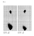
- FIG. 11 is a diagram representing distributions of pixels of sample A in the CIELAB color space and representing L*-a* relationship and a*-b* relationship when a lighting device is set at angles of 20 degrees and when the lighting device is set at 45 degrees and a*-b* relationship when the value of L* is set at 50.
- FIG. 12 is a diagram representing distributions of pixels of an image of sample A divided into eight regions with respect to a aspecular angle and representing L*-a* relationship in each region when the lighting device is set at 20 degrees and when the lighting devices is set at 45 degrees, and a*-b* relationship when the value of L* is set at 50.
- FIG. 13 is a diagram representing distributions of pixels of sample B in the CIELAB color space.
- FIG. 14 is a diagram representing distributions of pixels of sample B in the CIELAB color space and representing L*-a* relationship when the lighting device is set at 20 degrees and when the lighting device is set at 45 degrees, and a*-b* relationship when the value of L* is set at 50.
- FIG. 15 is a diagram representing distributions of pixels of an image of sample B divided into eight regions with respect to a aspecular angle and representing L*-a* relationship in each region when the lighting device is set at 20 degrees and when the lighting devices is set at 45 degrees, and a*-b* relationship when the value of L* is set at 50.
- FIG. 16 is a diagram illustrating another example of the present invention that incorporates three-dimensional geometry measurement means.
- FIG. 17 is a diagram illustrating means for acquiring spectral information when a point light source is used.
- FIG. 18 is a diagram illustrating means for acquiring spectral information when a linear light source is used.
- FIG. 19 is a diagram illustrating measured value changes with changes in geometrical conditions due to the orientation of effect materials.
- FIG. 20 is a diagram illustrating example measurements of interference effect materials.
- FIG. 22 is a diagram illustrating a monochrome two-dimensional image sensor.
- FIG. 23 is a diagram illustrating a Bayer-arrangement two-dimensional image sensor.
- FIG. 24 is a diagram illustrating a Foveon two-dimensional image sensor.
- FIG. 25 is a diagram illustrating a three-CCD two-dimensional image sensor.
- FIG. 26 is a diagram illustrating an example in which spectroscopic means is used at the illumination side.
- FIG. 27 is a diagram illustrating an example in which spectroscopic means is used at the illumination side and the light receiving side.
- FIG. 28 is a diagram illustrating an arrangement of a plurality of lighting devices.
- FIG. 29 is a diagram illustrating a state in which light sources placed symmetrically with respect to a vertical axis from the center of a sample surface are lit at the same time.
- FIG. 30 is a diagram illustrating an exemplary configuration of a measurement apparatus.
- FIG. 31 is a diagram illustrating an example in which a large sample such as a fender or a door is measured.
- FIG. 32 is a diagram illustrating an example in which a liquid sample or the like is measured.
- FIG. 33 is a diagram illustrating the frequency of appearance at different levels for explaining calibration coefficients.
- FIG. 34 is a diagram illustrating a position at which measured values can be considered identical when a linear light source is used.
- FIG. 35 is a diagram illustrating a position at which measured values can be considered identical when a point light source is used.
- FIG. 36 is a diagram illustrating a three-dimensional curved surface measurement.
- FIG. 37 is a diagram illustrating correction of a calibration coefficient.
- FIG. 1 is a diagram schematically illustrating a configuration of the present invention.
- An embodiment of a multi-angle spectral imaging apparatus of the present invention includes a monochrome two-dimensional image sensor 4 that is disposed in the direction perpendicular to a flat sample surface 2 to be measured and acquires a gray-scale image, an optical lens 8 that forms an image on the monochrome two-dimensional image sensor, spectroscopic means 6 , such as a liquid-crystal tunable filter, that is disposed in a predetermined position between the sample surface 2 to be measured and the optical lens 8 and whose passband is tunable, and a lighting device 10 having energy required for measurement in a measurement waveband.
- spectroscopic means 6 such as a liquid-crystal tunable filter
- One embodiment of the present invention is configured with a white reference surface 12 disposed around the sample surface 2 to be measured in parallel with the sample surface to be measured.
- An image of the white reference surface is taken together with the sample surface 2 to be measured. This image is used for correction made for accommodating changes in the amount of light of illumination and changes and errors in exposure time of an image pickup device during measurement.
- FIG. 2 is a diagram illustrating optical geometrical conditions in the present invention.
- Light emitted from the lighting device 10 illuminates the sample surface 2 to be measured and the white reference surface 12 .
- the monochrome two-dimensional image sensor 4 and the optical lens 8 are disposed so that the sample surface 2 to be measured and the white reference surface 12 are included together in an image taken. Note that the spectroscopic means 6 is omitted from FIG. 2 .
- Light emitted from the lighting device 10 illuminates the sample surface 2 to be measured and the white reference surface 12 .
- the illumination direction is dependent on the geometry being illuminated and varies from position to position on the sample surface 2 to be measured and the white reference surface 12 with respect to the direction perpendicular to the sample surface 2 to be measured and the white reference surface 12 .
- Specular reflection direction is opposite to the illumination direction, namely the mirrored direction of the illumination direction.
- the direction in which the pixels of the monochrome two-dimensional image sensor 4 taking an image of the sample surface 2 to be measured and the white reference surface 12 receive light varies from pixel to pixel and the unit vector 18 is denoted by P ij .
- i,j represent position of a pixel in the X axis and the Y axis of the image, respectively.
- (i, j) represents the coordinates of each pixel on a two-dimensional image.
- the unit vector 20 on the image in the illumination direction is denoted by I ij and the corresponding unit vector 16 in the specular reflection direction is denoted by S ij .
- the angle of the unit vector 18 in the light receiving direction with respect to the specular reflection direction of illumination is generally called aspecular angle 14 (hereinafter referred to as the “aspecular angle”).
- Metallic colors and pearlescent colors used for outer coating of automobiles change in hue (lightness, chroma and hue) depending on this angle.
- the aspecular angle at each pixel on an image is denoted by ⁇ ij and can be written as Formula 1.
- p ij ⁇ S ij represents the inner product of P ij and S ij .
- the aspecular angle ⁇ ij in the pixels of the monochrome two-dimensional image sensor 4 differs for different i and j and therefore has different angle information.
- Geometrical conditions for point P are: the zenith angle of illumination denoted by ⁇ il , the azimuth angle of illumination measured counterclockwise with respect to the X axis, denoted by ⁇ il , the zenith angle of light reception, denoted by ⁇ rsv , and the azimuth angle of light reception measured counterclockwise with respect to the X axis denoted by ⁇ rsv .
- ⁇ ij is a typical angle condition for identifying optical features of effect materials. It is useful that color space distributions are calculated and statistical parameters are calculated from an image in a region where ⁇ ij is the same.
- the lighting device 10 used is linear (a linear light source) as illustrated in FIG. 3 or a spot (a point light source) as illustrated in FIG. 4 .
- the optical lens 8 and the spectroscopic means 6 may be replaced with each other on condition that they can fulfil their respective functions.
- linear illumination different angle information is available in the X axis or Y axis direction of the image, depending on the direction in which the lighting device 10 is placed.
- spot illumination the illumination angle and light reception angle vary in both X and Y axis directions of the image and therefore different angle information in both directions are available.
- FIG. 7 illustrates a distribution of L* obtained from an image measured when the lighting device is set at 20 degrees
- FIG. 8 illustrates a distribution of L* obtained from an image measured when the lighting device is set at 45 degrees.
- FIG. 17 illustrates the case of the point light source.
- a position on the sample surface is denoted by P XY (x p , y p )
- the position of an illuminant is denoted by I( ⁇ i , ⁇ i , D i )
- a light receiving position is denoted by R(0, 0, D r ).
- x and y are positions in the X axis direction and Y axis direction, respectively, on the sample surface
- ⁇ is a zenith angle
- ⁇ is an azimuth angle measured counterclockwise from the X axis
- D i is the distance from the coordinate origin of the sample surface to the light source
- D r is the distance from the coordinate origin of the sample surface to an image pickup device. It is assumed that the image pickup device has a field angle large enough to cover an image taking range of the sample surface.
- Geometrical conditions of illumination and light receiving at position P can be represented by the zenith angle of the illumination, the azimuth angle of the illumination, the zenith angle of the light reception, and the azimuth angle of the light reception.
- FIG. 18 illustrates the case of a linear light source. If the light source is disposed parallel to the Y axis direction, illumination is uniform along the Y axis and optical geometrical conditions in this case are: a position on the sample surface denoted by P(x p ), the illumination position denoted by I( ⁇ i , D i ), and the light receiving position (focal point position) denoted by R(0, D r ).
- x is a position in the X axis direction and the Y axis direction on the sample surface
- ⁇ is a zenith angle
- D i is the distance from the coordinate origin to the illumination
- D r is the distance from the coordinate origin to an image pickup device.
- FIG. 19 illustrates changes of measured values with changes in geometrical conditions due to the orientation of effect materials.
- the effect materials have glittering reflection properties including specular reflection on its surface and exhibits strong directionality of reflection in the specular reflection direction. Because of the extremely strong reflection in the specular reflection direction, the amount of reflected light rapidly decreases as the distance of the observation position from the specular reflection direction increases. While glitter additive sizes are typically in the range of several micrometers to several tens of micrometers, some effect materials exceed 100 ⁇ m in size. This occurs because there are fluctuations in the distribution of light in the coating film formed by splay coating.
- Slight changes in optical geometrical conditions at each wavelength can lead to significant changes in the amount of reflected light near the specular reflection, which can prevent spectroscopic means from accurately measuring glittering reflection and can lead to a significant difference in distributions in the color space.
- effect materials made of aluminum flakes are silver in color and actually have a substantially constant reflectance factor at each wavelength, but if optical geometrical conditions vary from wavelength to wavelength, the spectral reflectance factor vary from wavelength to wavelength, which will produce false colors.
- changes in optical geometrical conditions will change interference conditions and will significantly affect the spectral reflectance factor and color values.
- FIG. 20 illustrates an example of measurement of interference effect materials.
- results of measurements on a product named Xirallic Crystal Silver from Merck KGaA are shown.
- a spectral reflectance factor measured has a sharp and narrow shape as a function of wavelength.
- a region of the lightest color that indicates a marginal domain of the object color and distributions were compared.
- Values in the CIELAB color space using artificial illuminant D65 at an observation view field of 10° were calculated from the measured spectral reflectance factors.
- a two-dimensional image sensor for image taking will be described below.
- the interference effect materials are often used in automobile coating today.
- the interference effect materials contain glittering reflection colors that are very fine and bright and have a wide color representation range. Multi-angle information is effectively used for such paint colors.
- a monochrome two-dimensional image sensor 4 is used in embodiments of the present invention to prevent occurrence of a moire image and the spectroscopic means is provided in a stage before the image pickup to implement a mechanism that acquires spectral information in a wide color gamut for every pixel.
- the two-dimensional image sensor 4 preferably includes an anti-blooming mechanism for identifying a good glittering reflected color with a high precision. If the two-dimensional image sensor 4 is a CCD image pickup sensor, it is desirable that the image sensor include means for preventing occurrence of noise in long time exposure by using a Peltier cooling device, a water cooling mechanism, an air cooling mechanism or a combination of these.
- the two-dimensional image sensor 4 has a dynamic range of 8 bits or greater, preferably 16 bits or greater in output resolution. Furthermore, it is desirable that the device include an anti-blooming mechanism.
- the two-dimensional image sensor 4 is preferably does not include a parallel arrangement of color RGB elements in order to prevent occurrence of false colors or moire in measurement in a minute region.
- Monochrome sensors do not cause such problems.
- RGB image pickup devices that do not rely on a parallel arrangement include three-CCD sensors and Foveon sensors.
- FIGS. 22 to 25 illustrate several types of two-dimensional image sensors.
- FIG. 22 illustrates a monochrome image sensor
- FIG. 23 illustrates a Bayer-arrangement color image sensor
- FIG. 24 illustrates a Foveon color image sensor
- FIG. 25 illustrates a three-CCD two-dimensional image sensor.
- the Foveon image sensor in FIG. 24 one pixel has R, G, B sensitivities.
- the monochrome two-dimensional image sensor in FIG. 22 is most efficient, and allows measurement with a high sensitivity.
- the Foveon color image sensor in FIG. 24 and the three-CCD two-dimensional image sensor in FIG. 25 do not use a parallel pixel arrangement and are capable of fast measurement.
- the Bayer arrangement color image sensor in FIG. 23 uses a parallel pixel arrangement, which can have adverse effects such as changes in geometrical conditions and occurrence of false colors.
- the optical lens 8 for image formation disposed before the monochrome two-dimensional image sensor 4 is preferably an optical lens with a high resolution, low distortion near the rim and low attenuation and preferably has a field angle of less than 40° in order to minimize image distortion near the rim.
- a mechanism capable of switching between at least two angles is provided to enable measurement at multiple aspecular angles (see FIGS. 1, 3 and 4 ).
- the spectroscopic means 6 provided immediately before the optical lens 8 may include a plurality of band-pass filers having different pass bands according to measurement wavelengths as illustrated in FIG. 1 and switching may be made from one filter to another to take images, thereby acquiring spectral information.
- a plurality of band-pass filers having different pass bands according to measurement wavelengths as illustrated in FIG. 1 and switching may be made from one filter to another to take images, thereby acquiring spectral information.
- 31 band-pass filters are provided and switching is made from one filter to another while repeating image taking at the same position to acquire 31 pieces of spectral information for all pixels.
- the spectroscopic means 6 only needs to disperse light incident on the two-dimensional image sensor 2 and may be disposed before the optical lens 8 or in a midway position between the optical lens 8 and the two-dimensional image sensor 2 , or immediately before the two-dimensional image sensor 2 .
- Means for producing monochromatic light may be a spectral light source device 40 that uses a white light illuminant having radiation energy that is sufficient for a desired wavelength range in which spectral information is to be acquired in combination with a reflective diffraction element, a transmission diffraction element, a prism or the like, or a spectral light source device in which a plurality of interference filters that filters light incident on a spectral device are replaced with one another, or a liquid-crystal tunable filter or a combination of band-pass filter such as AOTFs are used, or switching is made between single-wavelength illumination light sources.
- a mechanism uses one of or a combination of a lens, a mirror, or optical fiber and the like so that an illumination position and a light distribution pattern does not change while spectroscopically changing wavelength.
- a combination of two-dimensional monochrome image pickup devices or two-dimensional color image pickup devices is used.
- spectroscopic means may be used at both of the illumination side and the light reception side as illustrated in FIG. 27 .
- This can be used as a bispectral multi-angle spectral imaging apparatus to apply light to a fluorescent object.
- the spectroscopic means 6 only needs to disperse light incident on the two-dimensional image sensor 2 and may be provided before the optical lens 8 , in a midway position between the optical lens 8 and the two-dimensional image sensor 2 , or immediately before the two-dimensional image sensor 2 .
- a light source lamp such as a tungsten lamp, a halogen lamp, a xenon lamp, or a white LED with a mechanism such as optical fiber and a light guide or a light source lamp with a mirror, a projection lens and the like that is capable of illuminate the sample surface 2 to be measured and the white reference surface 12 at the same time may be used as the lighting device 10 . If the light distribution pattern or the spectral distribution provided by the lighting device 10 varies with changes in temperature, it is desirable to provide an appropriate cooling mechanism using Peltier cooling, water cooling, air cooling or a combination of these.
- FIG. 28 is a diagram illustrating an arrangement of a plurality of illuminants. As illustrated in FIG. 28 , the plurality of lighting devices 10 are arranged along the zenith angle direction and the azimuth angle direction or the Y axis direction, so that a point-like or linear illumination pattern can be provided from a plurality of angles without provision of a moving member.
- a combination of a plurality of illuminants can be lit at the same time to provide a wide variety of optical geometrical conditions and change spatial distributions of light sources.
- shadowless diffused illumination conditions can be produced by lighting light sources at positions that are symmetric with respect to the axis (the Z axis) perpendicular to the center of the sample surface as illustrated in FIG. 29 .
- the apparatus is contained in a rectangular housing 50 having a measurement window 52 in one face for placing a sample to be measured as illustrated in FIG. 30 so that the sample 2 can be brought into contact with and fixed on the housing 50 from the outside.
- a measurement window 52 in one face for placing a sample to be measured as illustrated in FIG. 30 so that the sample 2 can be brought into contact with and fixed on the housing 50 from the outside.
- measurement window 52 When the measurement window 52 is positioned at the top as illustrated in FIG. 31 , measurement of a large sample 54 such as a fender or a door can be easily made. Furthermore, measurement of powder or liquid in a glass cell can be made.
- a sample 56 such as a liquid sample, a viscous sample, powder, cosmetics or the like can be made.
- contactless measurement of a human organism and skin can be effectively made. This enables measurement of a translucent human organism without influence of changes in blood flow due to pressure or edge loss errors.
- a method for calibrating devices performed before actual measurement, and a method for measurement and image analysis calculations performed after the calibration will be described below with reference to FIGS. 5 and 6 .
- the method for calibrating the devices will be described with reference to FIG. 5 .
- Calibration is performed in order to address environmental changes such as temperature and humidity changes, instability of power supply, and changes in the light source devices and optical devices over time. Calibration is performed immediately after power-on the apparatus or several hours or days after the last calibration to make corrections so that measured values always fall within a certain error margin.
- a standard white plate for reference is provided (S 102 ).
- the surface structure is a lusterless diffusing surface and is uniform in a measurement range. It is desirable that the spectral reflectance factor of the surface structure is approximately 80% or greater in a measurement wavelength region.
- a typical standard white plate is a plate made of pressed barium sulfate powder.
- the spectral reflectance factor of the standard white plate at a wavelength ⁇ is measured beforehand with another calibrated spectrophotometer and is stored in a memory. The measured value is denoted by R c ( ⁇ ).
- the standard white plate is placed in place of a sample to be measured, an image of the standard white plate is taken at every measurement wavelength in illumination p, and the results are recorded in the memory.
- Each of the values is denoted by C ij (p, ⁇ ), where (i, j) represents the position of a pixel in an image of the standard white board taken.
- an image of the white reference surface provided around the standard white plate is also taken and recorded.
- Each of the values is denoted by W kl (p, ⁇ ), where (k, l) represents the position of a pixel in an image of the white reference surface taken.
- the surface structure of the white reference surface is a lusterless diffusing surface that is as much independent of light reception and illumination angles as possible. It is also desirable that the spectral reflectance factor of the white reference surface is approximately 80% or greater in a measurement wavelength region.
- exposure time may be optimized according to each measurement wavelength in order to correct the changes before calibration information is measured (S 103 , S 104 ).
- the calibration process ends (S 105 , S 106 ).
- the exposure times are stored along with the calibration information.
- the measurement is performed with the same exposure times that are stored here.
- the calibration method will be described in further detail with reference to FIG. 2 .
- the white reference surface 12 is set around a sample surface 2 to form a double-beam optical system.
- the white reference surface 12 is disposed inside the measurement window.
- the white reference surface 12 and the white calibration plate 3 placed in the sample setting location are measured at the same time to obtain a calibration coefficient at that point in time. Since two-dimensional image pickup devices are used, images of different regions of the white reference surface 12 and the sample surface 2 are taken at the same time.
- the values of the results of the image taking of the white reference surface 12 are stored in the memory.
- a standard white diffusion surface to which values are assigned or an alternative white surface with which the standard white diffusion surface can be referred to is used in calibration.
- the surface is referred to as the white calibration plate 3 .
- the white calibration plate 3 and the white reference surface 12 are measured at the same time to obtain calibration coefficients C I (x, y, ⁇ ).
- the subscript I represents the type (position) of an illuminant.
- the calibration coefficients can be obtained based on a level setting that takes into consideration the range of spectral reflectance factors that are possible in measurement.
- the level setting is a setting that associates an output count value from the two-dimensional image pickup device with a spectral reflectance factor of the white calibration plate 3 .
- the spectral reflectance factor of a standard white diffusion surface provided beforehand or an alternative white surface with which the standard white diffusion surface can be referred to is denoted by R W .
- the white calibration plate 3 has a uniform surface and the spectral reflectance factor R W does not change with optical geometrical conditions or regions.
- the spectral reflectance factor of the white reference surface 12 is denoted by R R .
- the reference surface has a uniform surface and the spectral reflectance factor R R does not change with optical geometrical conditions or regions.
- L max The maximum value output from an image pickup device
- L I the level setting value at illumination I for the white calibration plate 3
- Exposure time and the amount of light are adjusted so that the position of the distribution of output values V I (x, y, ⁇ ) from the image pickup device at illumination I and wavelength ⁇ is substantially peaked at the position of L I (the adjustments will be described later).
- the white calibration plate 3 and the white reference surface 12 are measured at the same time.
- the white calibration plate measured value is denoted by V I,W (x W , y W , ⁇ ) and the white reference surface measured value is denoted by V I,R (x R , y R , ⁇ ).
- the white reference surface measured value V I,R (x R , y R , ⁇ ) is stored in the memory. This is used for correction during measurement.
- the exposure time of the two-dimensional image pickup device is changed according to measurement wavelength and a difference in the light amount of the light source, a difference in the efficiency of the spectroscopic means (a difference in transmittance or the like), and a difference in the spectral sensitivity of the image pickup device at the wavelength are corrected to ensure a high dynamic range.
- Exposure time is multiplexed, like setting short-exposure time and long-exposure time, to extend the dynamic range.
- Exposure time is multiplexed by multiplexing level setting or providing a low-reflectance calibration plate (gray or black or the like).
- Adjustment of the exposure time during calibration is automatically optimized by computer control based on the distribution of measurement count values during the calibration. Exposure time can be adjusted manually as well.
- a method for extending the dynamic range other than multiplexing the exposure time is to multiplex the light amount of illumination.
- electrical energy supplied to the illuminant or the number of illuminants may be multiplexed.
- the calibration plate described above may be replaced or the level setting may be changed.
- multiplexing of exposure time and multiplexing of the light amount of illumination may be combined.
- the sample surface 2 and the white reference surface 12 are measured at the same time with the exposure time optimized for each wavelength, the measured values are compared with the measured count values of the white reference surface recorded during calibration, and correction is made.
- Changes to be corrected include changes in the light amount of illumination, changes in the spectroscopic means (for example changes in the efficiency of dispersion due to changes in transmittance of a filter), changes in the sensitivity of a two-dimensional image pickup device, errors in exposure time (especially in short-time exposure) and the like.
- the white reference surface measured values V I,R (x R , y R , ⁇ ) at illumination I and wavelength ⁇ at the time of calibration have been stored in the memory. While an example measurement method will be described below, the method for interpolation calculation of a time correction coefficient for a sample surface is not limited to this; various methods such as two-dimensional spline interpolation may be used.
- the range of X R is X b ⁇ x R ⁇ x e and the range of y R is y b ⁇ y R ⁇ y e .
- F 0 F I ( x p ,y b , ⁇ ) ⁇ [( y e ⁇ y p )/( y e ⁇ y b )]+ F I ( x p ,y e , ⁇ ) ⁇ [( y p ⁇ y b )/( y e ⁇ y b )] [Expression 15]
- the displacement is obtained for each illumination condition.
- the time correction coefficient for each illumination condition is denoted by F ij (I, ⁇ ).
- the subscripts ij represent a position on the white reference surface (which is the same as the position on a sample surface) corresponding to x R , y R in the formula given earlier.
- a sample to be measured is set (S 111 ), an image is taken with each measurement wavelength (S 112 ) and the result is recorded in a memory (S 113 ).
- the value is denoted by V Mij (I, ⁇ ).
- F ij (I, ⁇ ) described above is obtained from a measured value of the image of the white reference surface taken at the same time.
- the spectral reflectance factor R ij (I, ⁇ ) of the sample to be measured after calibration can be obtained according to Formula 17.
- the calibration coefficient for the illumination I is C ij (I, ⁇ ).
- a pixel position on the white reference surface is obtained by referring to a position that effectively works on a pixel position (i, j) on the sample surface to be measured for which correction is made, for example a position on the white reference surface that intersects with a line drawn from a position to be measured in parallel to the X axis and with a line drawn from the position in parallel to the Y axis as an extrapolation position for the X axis and the Y axis or applying partial interpolation and averaging.
- Measurement of the white reference surface is made at the same time as the time of image taking and measured values are used for correction for accommodating changes in the light amount of illumination and changes and errors in exposure time of an image pickup device during measurement. This enables high-precision and stable measurement.
- a light trap or a standard black plate may be used in measurement of calibration data to make corrections to spectral reflectance factors near 0.
- regions for which optical geometrical conditions can be considered to be the same are a region along the Y axis that has a width dx along the X axis, as depicted in FIG. 34 (the shaded region) when linear light sources are used and a small region where changes in optical geometrical conditions are negligible.
- image information under substantially identical optical geometrical conditions can be obtained and can be used as information for obtaining distributions in a color space and feature quantities in an image.
- R mij (p, ⁇ ) A method for obtaining the average of measured spectral reflectance factors R mij (p, ⁇ ) for all pixels with each illuminant with respect to multi-angle information will be described (S 115 ).
- the aspecular angle differs from pixel position (i, j) to pixel position.
- the average R m (p, ⁇ ) of spectral reflectance factors can be written as Formula 18.
- R m ( p , ⁇ ) ⁇ R mij ( p , ⁇ )/ N [Expression 18]
- ⁇ is calculated for the region from the i-th pixel to the i+I-th pixel in the X axis direction and the region from the j-th pixel to the j+J-th pixel in the Y axis direction.
- the average spectral reflectance factor R mij (p, ⁇ ) can be obtained at any aspecular angle ⁇ (p) for a desired spatial resolution can be obtained by choosing i, j, I and J appropriately.
- I and J are chosen to be small, changes in aspecular angle ⁇ (p) in the average calculation region will be small and the average can be calculated with a high spatial resolution.
- I and J are chosen to be large, the spatial resolution will decrease but the effects of averaging and smoothing will be high because N is large.
- Parameters such as lightness distributions for different angles, color spatial distributions, spatial distribution for each image position, the number of appearing colors, information entropy, and image filters, fractal dimensions and other parameters can be calculated and displayed as obtained multi-angle spectral image information.
- reproduction information can be provided by computer graphics.
- X ij (p), Y ij (p), Z ij (P) of each pixel can be written as Formula 20.
- X ij ( p ) k ⁇ P ( ⁇ ) x ( ⁇ ) R mij ( p , ⁇ ) d ⁇
- Y ij ( p ) k ⁇ P ( ⁇ ) y ( ⁇ ) R mij ( p , ⁇ ) d ⁇
- P( ⁇ ) represents a spectral distribution of illumination light that is possible when an object is observed and the range of wavelengths ⁇ to be integrated is a visible light region used in the measurement.
- the tristimulus values X ij (p), Y ij (p), Z ij (P) are converted to R ij (p), G ij (p), B ij (P) values.
- Methods for converting to sRGB and Adobe RGB based on standards are known.
- a method for obtaining color values from the tristimulus values X ij (p), Y ij (p), Z ij (p) of all pixels measured will be described.
- a typical method is to obtain L*a*b* which are values in the CIELAB color space specified in CIE by using Formula 22.
- X n , Y n , and Z n are tristimulus values obtained by measurement of an object having a spectral reflectance factor of 100%.
- the average of CIELAB values can be obtained according to Formula 23.
- An important method for acquiring features of a sample 2 to be measured by image analysis is to obtain a distribution of measured values in the CIELAB color space.
- the region from the i-th pixel to the i+I-th pixel along the X axis of the image and the region from the j-th pixel to the j+J-th pixel along the Y axis are calculated.
- a method for calculating the number of colors that appeared and a method for calculating information entropy can be used as a method for representing distributions of measured values in the CIELAB color space as numerical parameters.
- P(p, c) is the frequency of appearance of color c in an image taken with illumination p and is calculated by dividing the region from the i-th pixel to the i+I-th pixel along the X axis and the region from the j-th pixel to the j+J-th pixel along the Y axis into cubes with edges ⁇ L*, ⁇ a*, ⁇ b* of a certain length.
- Various other methods can also be used, such as a method of using an image filter or differential values, or performing frequency analysis such as Fourier transform or wavelet transform on an image position, i.e. a aspecular angle ⁇ (p), which is a geometrical condition of illumination and light reception, and a method of parameterizing distributions in the CIELAB color space in further detail.
- a method of using an image filter or differential values or performing frequency analysis such as Fourier transform or wavelet transform on an image position, i.e. a aspecular angle ⁇ (p), which is a geometrical condition of illumination and light reception
- ⁇ (p) which is a geometrical condition of illumination and light reception
- Spectral information on a sample surface of a planar object to be measured is acquired using changes in optical geometrical conditions from pixel to pixel in the description given above.
- Accurate measurement of a curved surface to be measured can be made as well by incorporating a three-dimensional measurement device in a multi-angle spectral imaging apparatus and correcting optical geometrical conditions from the normal to each pixel of the curved surface.
- Displacements in the Z axis direction of the sample surface and the normal direction are measured from the three-dimensional geometry and corrections are made to the optical geometrical conditions ( ⁇ il , ⁇ il , ⁇ rsv , ⁇ rsv ) described above.
- a position on the sample surface is denoted by P(x p , y p )
- the position of a lighting device is denoted by I( ⁇ i , ⁇ i , D i )
- the position of a light receiving device is denoted by R(0, 0, D r ).
- x and y are positions in the X axis direction and Y axis direction, respectively, on the sample surface
- ⁇ is a zenith angle
- ⁇ is an azimuth angle measured counterclockwise from the X axis
- D i is the distance from the sample surface to the light source
- D r is the distance from the sample surface to an image pickup device. It is assumed that the image pickup device has a field angle large enough to cover an image taking range of the sample surface.
- Geometrical conditions of illumination and light receiving at position P can be represented by the zenith angle of the illumination, the azimuth angle of the illumination, the zenith angle of the light reception, and the azimuth angle of the light reception.
- the unit vector as the axis of the rotation is ( ⁇ sin ( ⁇ n ), cos ( ⁇ n ), ⁇ ).
- the general expression of the rotation ⁇ about an arbitrary vector (n x , n y , n z ) is [Expression 29] [Math 1]
- the calibration coefficients need to be corrected when there are changes in position and angle. That is, the calibration coefficient is recalculated using a displacement D H in the vertical direction and an inclination with respect to the illumination position. This is done because the irradiation energy per unit area changes with the displacement and the inclination.
- FIG. 37 is a diagram illustrating correction of a calibration coefficient.
- a position on the XYZ Cartesian coordinates of the illumination is denoted by I(x i , y i , z i ) and the observation position on the sample surface is denoted by P(x p , y p , 0).
- the calibration coefficient C is corrected according to the following formula.
- C′ C ⁇ ( D I +D H )/ D I [Expression 33]
- the unit vector at point P in the direction of illumination is denoted by (n Ix , n Iy , n Iz ) and the unit vector of point P with respect to the three-dimensional curved surface is denoted by (n Hx , n Hy , n Hz ). Because the unit vector of point P in the vertical direction is (0, 0, 1), the inner product of this unit vector and the unit vector in the direction of illumination is n Iz .
- the method for obtaining the correction coefficient is not limited to this; any of various methods can be used.
- the monochrome two-dimensional image sensor 4 including a Peltier cooling mechanism and an anti-blooming mechanism and having 772 pixels in the X axis direction and 580 pixels in the Y axis direction was used.
- the imaging lens was a single-focus C mount lens having a focal length of 25 mm and a longitudinal field angle of 22 degrees.
- the spectroscopic means had a liquid-crystal tunable filter immediately before the lens and was capable of spectral measurement in the visible light range at intervals of 10 nm.
- the central area of an image that has 720 pixels in the X axis direction and 520 pixels in the Y axis direction was used and the other, marginal area was a white reference surface.
- two sets of linearly arranged 10 white LED chips each of which included a projection lens were provided and were disposed so that the sample surface to be measured was illuminated at angles of 20 degrees and 45 degrees from the direction perpendicular to the center of the sample surface to be measured.
- a standard white plate which is a standard calibration plate
- calibration information at each wavelength was measured with the illuminants at 20 degrees and 45 degrees.
- exposure time was optimized for each measurement wavelength and was stored along with the calibration information in the memory. Then, the sample to be measured was set at the measurement place and measurement was made with illuminants at 20 degrees and 45 degrees for each wavelength with the same exposure times as those in the calibration.
- Sample A (a color card containing aluminum flake pigment (Alpate 7670 NS from Toyo Aluminium K.K.)) and sample B (a color card containing interference effect materials (Xirallic Crystal Silver XT60-10 from Merck)) were measured. After the measurement of both of the samples, spectral reflectance factors for all pixels with illuminants at 20 degrees and 45 degrees were obtained based on the calibration information. From the spectral reflection coefficients, tristimulus values XYZ, RGB values for image display, and values in the CIELAB color space were obtained.
- FIG. 9 illustrates a graph of results of the measurement of spectral reflectance factors obtained by dividing each of images with illuminants at 20 degrees and 45 degrees into eight regions in the X axis direction, averaging the measured values of the pixels in each of the total of 16 regions, and changing the wavelength in increments of 10 nm in the range of 400 nm to 700 nm.
- the number of colors that appeared in the image in the CIELAB color space can be used as an indicator of a feature of the color card.
- a color card that uses only a pigment as coloring agent and has a paint color generally called solid color
- measured values in the image are substantially the same and therefore extremely few colors appear in the image.
- a metallic color the lightness and chroma particularly vary depending on the type and blending quantity of aluminum effect materials contained, pigments used in combination with the effect materials, and optical geometrical conditions, and therefore more colors appear.
- the hue as well as lightness and chroma vary according to optical geometrical conditions and, in addition, interference reflected light from fine effect materials are contained and therefore various colors appear in each individual pixel, which increases the number of appearing colors. This means that colors distribute in a wider range in the CIELAB color space.
- the information entropy is a numerical value indicating the amount of information in an image and can be used as an indicator of a feature of a color card, like the number of appearing colors.
- P(i) is the frequency of appearance of color i in the image and represents how many pixels are included in a cube with an edge of 1.00 along each of the L*, a* and b* axes.
- FIG. 10 illustrates distributions in the CIELAB color space for sample A and FIG. 11 illustrates the L*-a* relationship with illuminants at 20 degrees and 45 degrees and the a*-b* relationship when the value of L* was set at 50.
- FIG. 13 illustrates distributions in the CIELAB color space for sample B and FIG. 14 illustrates the L*-a* relationship with illuminants at 20 degrees and 45 degrees and the a*-b* relationship when the value of L* was set at 50.
- FIG. 12 illustrates the L*-a* relationship in the eight regions of sample A with illuminants at 20 degrees and 45 degrees and the a*-b* relationship when the value of L* was set at 50
- FIG. 15 illustrates the L*-a* relationship in the eight regions of sample B with illuminants at 20 degrees and 45 degrees and the a*-b* relationship when the value of L* was set at 50.
- the distributions for the interference effect materials of sample A is wider than the distributions for the aluminum effect materials of sample B because the interference effect materials of sample A have interference glittering reflections. The difference between the samples is clearly shown.
- a white reference surface 12 may be omitted and only the sample surface 2 may be measured.
- a white light source is used as the lighting device 10 in this embodiment, a light source that has dispersion facility in the lighting device and is capable of emitting single-wavelength light may be used.
- a flat object to be measured is used to acquire spectral information of a sample surface from changes in optical geometrical conditions of each pixel in this embodiment.
- a three-dimensional geometry measurement device may be incorporated in the multi-angle spectral imaging apparatus so that optical geometrical conditions can be accurately corrected based on the normal to each of the pixels on the curved surface.
- FIG. 16 Another example in which a three-dimensional geometry measurement device is incorporated will be described with reference to FIG. 16 . Description of the same components as those in the example described above will be omitted.
- This example includes, as in the first example, a monochrome two-dimensional image sensor 4 , a liquid-crystal tunable filter which acts as spectroscopic means 6 , and a lighting device 10 including two sets of linearly arranged 10 white LED chips.
- this example includes a laser projector 9 (SHOWWX from Microvision, Inc., USA) as geometry measurement means for three-dimensional geometry correction of a sample to be measured.
- the laser projector 9 is used to project a grating image 11 onto a surface to be measured, the grating image 11 is captured with the monochrome two-dimensional image sensor 4 , and a geometry is obtained from displacements of the grating image 11 .
- a sufficiently flat standard white plate which is a standard calibration plate, was set in a measurement place after power-on and then calibration information at each wavelength was measured with illuminants at 20 degrees and 45 degrees. Then, the laser projector 9 for three-dimensional geometry measurement was used to project a grating image, an image of the projected grating image was taken with the monochrome two-dimensional image sensor 4 , and positions on the grating image 11 were quantified as data on a reference flat surface and stored.
- the grating image 11 was projected with the laser projector 9 , the grating image was acquired with the monochrome two-dimensional image sensor 4 , and position information on the grating image 11 on the reference flat surface that has measured and stored beforehand was used to calculate three-dimensional geometry data by a triangular method.
- optical geometrical conditions can be accurately corrected because the three-dimensional geometry measurement device is incorporated in the multi-angle spectral imaging apparatus in order to measure a curved surface to be measured.
- the three-dimensional geometry measurement device is incorporated in the multi-angle spectral imaging apparatus in order to measure a curved surface to be measured.
- normal vectors are calculated from the three-dimensional geometry, specular reflection directions of illumination are corrected, then the aspecular angles are recalculated, thereby enabling measurement unaffected by the geometry of the surface to be measured.
- an object other than solids such as a fluid surface, liquid, and powder, can be measured contactlessly.
Landscapes
- Physics & Mathematics (AREA)
- Spectroscopy & Molecular Physics (AREA)
- General Physics & Mathematics (AREA)
- General Health & Medical Sciences (AREA)
- Pathology (AREA)
- Chemical & Material Sciences (AREA)
- Analytical Chemistry (AREA)
- Biochemistry (AREA)
- Health & Medical Sciences (AREA)
- Immunology (AREA)
- Life Sciences & Earth Sciences (AREA)
- Engineering & Computer Science (AREA)
- Mathematical Physics (AREA)
- Theoretical Computer Science (AREA)
- Human Computer Interaction (AREA)
- Investigating Or Analysing Materials By Optical Means (AREA)
- Spectrometry And Color Measurement (AREA)
Abstract
Description
δij=cos−1(p ij ·S ij) [Expression 1]
θas=θil
φas=φil+π [Expression 2]
Therefore,
n xa=sin(θas)·cos(φas)
n ya=sin(θas)·sin(φas)
n za=cos(θas) [Expression 3]
On the other hand, in the case of light reception angle
n xr=sin(θrsv)·cos(φrsv)
n yr=sin(θrsv)·sin(φrsv)
n zr=cos(θrsv) [Expression 4]
The angle is inversely calculated from the inner product as
δij=cos−1(n xa ·n xr +n ya ·n yr +n za ·n zr) [Expression 5]
x i =D i·sin(θi)·cos(φi)
y i =D i·sin(θi)·sin(φi)
z i =D i·cos(θi) [Expression 6]
x i ′=x i −x p
Y i ′=y i −y p [Expression 7]
and the relative coordinate position of light reception in the xy plane for point P can be written as: [Expression 8]
x r ′=−x p
y r ′=−y p
Then geometric conditions (θil, φil, θrvs, φrvs) are
θil=π/2−tan−1(Z i/sqrt((x i′)2+(y i′)2)) (sqrt represents square root; the same applies to the following formulas.)
φil=tan−1(y i′ /x i′)
θrsv=π/2−tan−1(z r′/sqrt((x r′)2+(y r′)2))
φrsv=tan−1(y r′ /x r′) [Expression 9]
x i =D i·sin(θi)
z i =d i·cos(θi) [Expression 10]
x i ′=x i −x p
z i ′=z i [Expression 11]
and the relative coordinate position of light reception in the xy plane for point P can be written as:
x r ′=−x p
z r ′=−D r [Expression 12]
θil=π/2−tan−1(z i ′/|x i′|)
θrsv=π/2−tan−1(z r ′/|x r′|) [Expression 13]
C I(x W ,y W,λ)=R W /V I,W(x W ,y W,λ).
F I(x R ,y R,λ)=V I,RM(x R ,y R,λ)/V I,R(x R ,y R,λ) [Expression 14]
F 0 =F I(x p ,y b,λ)·[(y e −y p)/(y e −y b)]+F I(x p ,y e,λ)·[(y p −y b)/(y e −y b)] [Expression 15]
ΔF xb =F I(x b , y p, λ)−F I(x b , y b, λ)·[(y e −y p)/(y e −y b)]−F I(x b , y e, λ)·[(y p −y b)/(y e −y b)]
ΔF xe =F I(x e , y p,λ)−F I(x e , y b, λ)·[(y e −y p))/(y e −y b)]−f I(x e , y e, λ)·[(y p −y b)/(y e −y b)] [Expression 16]
R ij(I, λ)=V Mij(I, λ)·C ij(I, λ)/F ij(I, λ) [Expression 17]
R m(p, λ)=ΣΣR mij(p, λ)/N [Expression 18]
θ(p)=ΣΣθij(p)/N [Expression 19]
X ij(p)=k∫P(λ)x(λ)R mij(p,λ)dλ
Y ij(p)=k∫P(λ)y(λ)R mij(p,λ)dλ
Z ij(p)=k∫P(λ)x(λ)R mij(p,λ)dλ
K=100/∫P(λ)y(λ)dλ [Expression 20]
Here, P(λ) represents a spectral distribution of illumination light that is possible when an object is observed and the range of wavelengths λ to be integrated is a visible light region used in the measurement. When presented on a computer display or a printer, the tristimulus values Xij(p), Yij(p), Zij(P) are converted to Rij(p), Gij(p), Bij(P) values. Methods for converting to sRGB and Adobe RGB based on standards are known.
X(p)=ΣΣX ij(p)/N
Y(p)=ΣΣY ij(p)/N
Z(p)=ΣΣZ ij(p)/N [Expression 21]
L* ij(p)=116f(Y ij(P)/Y n)−16
a* ij(P)=500{f(X ij(p)/X n)−f(Y ij(p)/Y n)}
b*ij(p)=200{f(Y ij(p)/Y n)−f(Z ij(p)/Z n)} [Expression 22]
Here,
- when Xij(p)/Xn>0.00856, f(Xij(p)/Xn)=(Xij(p)/Xn)1/3 when X ij(p)/Xn<0.00856, f(Xij(p)/Xn)=7.787 (Xij(p)/Xn)+16/116
- when Yij(p)/Yn>0.00856, f (Yij(p)/Yn)=(Yij(p)/Yn)1/3 when Y ij(p)/Yn<0.00856, f(Yij(p)/Yn)=7.787 (Xij(p)/Xn)+16/116
when Zij(p)/Zn>0.00856, f(Zij(p)/Zn)=(Zij(p)/Zn)1/3 when Z ij(p)/Zn<0.00856, f(Zij(p)/Zn)=7.787 (Zij(p)/Zn)+16/116
L*(p)=ΣΣL* ij(p)/N
a*(p)=ΣΣa* ij(p)/N
b*(p)=ΣΣb* ij(p)/N [Expression 23]
H(p)=−ΣP(p,c)log2 {P(p,c)} [Expression 24]
x i =D i·sin(θi)·cos(φi)
y i =D i·sin(θi)·sin(φi)
z i =D i·cos(θi) [Expression 25]
x i ′=x i −x p
y i ′=y i −y p
z i ′=z i [Expression 26]
and the relative coordinate position of the light reception with respect to point P is
x r ′=−x p
y r ′=−y p
z r ′=z r [Expression 27]
x i ″=x i′
y i ″=y i′
z i ″=z i ′−D H
x r ″=x r′
y r ″=y r′
z r ″=z r ′−D H [Expression 28]
If the normal vector is inclined at a zenith angle of θn in the φn direction, the same operation as rotation by −θn about the straight line that is perpendicular to the positions of the illumination I″ and the light receiving position R″ and passes through the relative coordinate X″Y″ plane. The unit vector as the axis of the rotation is (−sin (φn), cos (φn), θ). The general expression of the rotation θ about an arbitrary vector (nx, ny, nz) is
[Expression 29]
[Math 1]
θil=π/2−tan−1(z i′″/sqrt((x i′″)2+(y′″)2)
φil=tan−1(y i ′″/x i′″)
θrsv=π/2−tan−1(z r′″/sqrt((x p′″)2+(y p′″)2))
φrsv=tan−1(y r ′″/x r′″) [Expression 31]
D I=[(x i −x p)2+(y i −y p)2 +z p 2]0.5 [Expression 32]
When there is a change DH in the distance, the calibration coefficient C is corrected according to the following formula.
C′=C·(D I +D H)/D I [Expression 33]
cos(θI)=n Iz
θI=cos−1(n Iz) [Expression 34]
In this case, the projected area of light per unit area is
S I=1/cos(θI) [Expression 35]
On the other hand, the inner product A of the direction of illumination and the normal direction is
A=n Ix ·n Hx +n Iy ·n Hy +n Iz ·n Hz
θIH=cos−1(A) [Expression 36]
Therefore, the projected area in this case is
S IH=1/cos(θIH) [Expression 37]
The correction coefficient in this case is
C″=C′(S I /S IH)=C·[(D I +D H)/D I]·[cos(θIH)/cos(θI)] [Expression 38]
The method for obtaining the correction coefficient is not limited to this; any of various methods can be used.
E=−ΣP(i)log2 {P(i)} [Expression 39]
- 2 Sample surface (sample surface to be measured)
- 3 White calibration plate
- 4 Two-dimensional image sensor
- 6 Spectroscopic means
- 8 Optical lens
- 9 Laser projector
- 10 Lighting device
- 11 Grating image
- 12 White reference surface
- 14 Aspecular angle
- 16 Unit vector in specular reflection direction
- 18 Unit vector in light receiving direction
- 19 Pixel (i, j)
- 20 Unit vector in illumination direction
- 32 Lighting direction
- 34 Specular reflection direction
- 36 Observation direction
- 38 Normal direction of effect materials
- 40 Spectral light source device
- 50 Housing
- 52 Measurement window
- 54 Large sample such as fender or door
- 56 Liquid sample
Claims (7)
Priority Applications (1)
| Application Number | Priority Date | Filing Date | Title |
|---|---|---|---|
| US15/265,816 US9823130B2 (en) | 2012-04-20 | 2016-09-14 | Multi-angle spectral imaging measurement method and apparatus |
Applications Claiming Priority (7)
| Application Number | Priority Date | Filing Date | Title |
|---|---|---|---|
| JP2012097170 | 2012-04-20 | ||
| JP2012-097170 | 2012-04-20 | ||
| JP2012126389A JP5475057B2 (en) | 2012-04-20 | 2012-06-01 | Variable angle spectroscopic imaging measurement method and apparatus |
| JP2012-126389 | 2012-06-01 | ||
| PCT/JP2013/061671 WO2013157641A1 (en) | 2012-04-20 | 2013-04-19 | Variable angle spectroscopic imaging measurement method and device therefor |
| US201414395476A | 2014-10-18 | 2014-10-18 | |
| US15/265,816 US9823130B2 (en) | 2012-04-20 | 2016-09-14 | Multi-angle spectral imaging measurement method and apparatus |
Related Parent Applications (2)
| Application Number | Title | Priority Date | Filing Date |
|---|---|---|---|
| US14/395,476 Division US20150131090A1 (en) | 2012-04-20 | 2013-04-19 | Multi-angle spectral imaging measurement method and apparatus |
| PCT/JP2013/061671 Division WO2013157641A1 (en) | 2012-04-20 | 2013-04-19 | Variable angle spectroscopic imaging measurement method and device therefor |
Publications (2)
| Publication Number | Publication Date |
|---|---|
| US20170010158A1 US20170010158A1 (en) | 2017-01-12 |
| US9823130B2 true US9823130B2 (en) | 2017-11-21 |
Family
ID=49383589
Family Applications (2)
| Application Number | Title | Priority Date | Filing Date |
|---|---|---|---|
| US14/395,476 Abandoned US20150131090A1 (en) | 2012-04-20 | 2013-04-19 | Multi-angle spectral imaging measurement method and apparatus |
| US15/265,816 Expired - Fee Related US9823130B2 (en) | 2012-04-20 | 2016-09-14 | Multi-angle spectral imaging measurement method and apparatus |
Family Applications Before (1)
| Application Number | Title | Priority Date | Filing Date |
|---|---|---|---|
| US14/395,476 Abandoned US20150131090A1 (en) | 2012-04-20 | 2013-04-19 | Multi-angle spectral imaging measurement method and apparatus |
Country Status (5)
| Country | Link |
|---|---|
| US (2) | US20150131090A1 (en) |
| EP (1) | EP2840368B1 (en) |
| JP (1) | JP5475057B2 (en) |
| CN (1) | CN104471361B (en) |
| WO (1) | WO2013157641A1 (en) |
Cited By (1)
| Publication number | Priority date | Publication date | Assignee | Title |
|---|---|---|---|---|
| WO2008053153A2 (en) | 2006-11-01 | 2008-05-08 | Solarflare Communications Inc. | Driver level segmentation offload |
Families Citing this family (47)
| Publication number | Priority date | Publication date | Assignee | Title |
|---|---|---|---|---|
| US20150022658A1 (en) * | 2013-07-16 | 2015-01-22 | University Of North Carolina At Charlotte | Noise reduction techniques, fractional bi-spectrum and fractional cross-correlation, and applications |
| WO2015125311A1 (en) * | 2014-02-24 | 2015-08-27 | オリンパス株式会社 | Spectroscopic measurement method |
| WO2015133287A1 (en) * | 2014-03-07 | 2015-09-11 | 新日鐵住金株式会社 | Surface texture indexing device, surface texture indexing method, and program |
| DE102014009372B4 (en) * | 2014-06-23 | 2025-04-30 | Fraunhofer-Gesellschaft zur Förderung der angewandten Forschung e.V. | Method for determining properties and/or parameters of a sample and/or at least one layer formed on a surface of a sample |
| JP6478492B2 (en) * | 2014-06-27 | 2019-03-06 | キヤノン株式会社 | Image processing apparatus and method |
| JP6390252B2 (en) * | 2014-08-05 | 2018-09-19 | 株式会社リコー | Sample measuring apparatus and sample measuring program |
| JP6384183B2 (en) | 2014-08-05 | 2018-09-05 | 株式会社リコー | Sample measuring apparatus and sample measuring program |
| DE102015217091B4 (en) | 2015-09-07 | 2017-05-11 | Fraunhofer-Gesellschaft zur Förderung der angewandten Forschung e.V | Arrangement for determining the achievable adhesive strength before formation of a material-locking connection on a surface of a joining partner |
| AT518675A1 (en) * | 2016-05-19 | 2017-12-15 | H & P Trading Gmbh | Method and device for determining at least one test property of a test object |
| JP6922482B2 (en) * | 2016-07-04 | 2021-08-18 | 株式会社リコー | Measurement system, reflectance calculation method and program |
| JP6907766B2 (en) * | 2016-07-05 | 2021-07-21 | 株式会社リコー | Measuring equipment and measuring system |
| JP6754674B2 (en) | 2016-11-08 | 2020-09-16 | 昭和電工株式会社 | Evaluation method of tantalum carbide |
| US10559085B2 (en) | 2016-12-12 | 2020-02-11 | Canon Kabushiki Kaisha | Devices, systems, and methods for reconstructing the three-dimensional shapes of objects |
| JP2018125769A (en) * | 2017-02-02 | 2018-08-09 | パイオニア株式会社 | Imaging apparatus, imaging method, program, and recording medium |
| JP2018151832A (en) * | 2017-03-13 | 2018-09-27 | キヤノン株式会社 | Information processing apparatus, information processing method, and program |
| US10267899B2 (en) | 2017-03-28 | 2019-04-23 | Luminar Technologies, Inc. | Pulse timing based on angle of view |
| US20200064194A1 (en) * | 2017-05-03 | 2020-02-27 | X-Rite Switzerland GmbH | Vehicle color measurement methods and devices |
| CN107389197B (en) * | 2017-07-27 | 2018-07-17 | 中原工学院 | A kind of color depth characterizing method based on spectral reflectance and CIE color specification systems |
| EP3450938B1 (en) * | 2017-08-30 | 2022-10-12 | IMEC vzw | An image sensor and an imaging apparatus |
| CN107991303B (en) * | 2017-12-18 | 2024-04-26 | 云南烟叶复烤有限责任公司 | Threshing and stem removing quality detection device and detection method based on double-spectrum technology |
| KR102500640B1 (en) | 2018-03-02 | 2023-02-15 | 제이에프이 스틸 가부시키가이샤 | Furnace control method |
| CN112272765B (en) * | 2018-05-03 | 2025-03-07 | 乌斯特技术股份公司 | Textile brightness measurement system |
| KR102663185B1 (en) * | 2018-08-07 | 2024-05-03 | 삼성전자주식회사 | Optical emission spectroscopy system and method of calibrating the same, and method of fabricating semiconductor device |
| CN109283186A (en) * | 2018-10-12 | 2019-01-29 | 成都精工华耀科技有限公司 | A kind of double spectrum two-dimensionals of track visualization inspection and three-dimensional fusion imaging system |
| JP7192447B2 (en) * | 2018-11-30 | 2022-12-20 | セイコーエプソン株式会社 | Spectroscopic camera and electronics |
| JP7387985B2 (en) * | 2018-12-13 | 2023-11-29 | 株式会社リコー | Painted surface evaluation method, painted surface evaluation device, and program |
| CN110095136B (en) * | 2019-03-27 | 2023-12-01 | 苏州德沃物流科技有限公司 | Binocular vision three-dimensional reconstruction calibration device and method integrating IMU pose correction |
| JP7326972B2 (en) | 2019-07-30 | 2023-08-16 | 株式会社リコー | Surface Characteristic Evaluation Method, Surface Characteristic Evaluation Apparatus, and Surface Characteristic Evaluation Program |
| CN114424046B (en) * | 2019-09-27 | 2024-09-27 | 松下知识产权经营株式会社 | Inspection method, recording medium, and inspection system |
| EP4055370B1 (en) * | 2019-11-06 | 2024-08-14 | Uster Technologies AG | Apparatus and method for optically characterizing a textile sample |
| JP2021103129A (en) * | 2019-12-25 | 2021-07-15 | 株式会社イマジオム | Color pattern determination probe and color pattern determination device |
| JP7497622B2 (en) * | 2020-06-05 | 2024-06-11 | セイコーエプソン株式会社 | Image generating device and image generating method |
| JP7799375B2 (en) * | 2020-07-02 | 2026-01-15 | キヤノン株式会社 | Image processing device, image processing method and program |
| US12582290B2 (en) * | 2021-04-01 | 2026-03-24 | Gyrus Acmi, Inc. | Techniques for composition identification of an anatomical target |
| CN113295387B (en) * | 2021-05-25 | 2023-11-17 | 中国科学院合肥物质科学研究院 | A multi-band strip filter optical parameter testing system and its testing method |
| CN113409379B (en) * | 2021-06-30 | 2022-08-02 | 奥比中光科技集团股份有限公司 | Method, device and equipment for determining spectral reflectivity |
| US12581200B2 (en) * | 2021-11-29 | 2026-03-17 | Waymo Llc | Control window camera direction to avoid saturation from strong background light and actively adjust the frame time on the spinning camera to achieve directional control |
| JP7760904B2 (en) * | 2021-12-14 | 2025-10-28 | セイコーエプソン株式会社 | Spectroscopic imaging method, spectroscopic imaging device, and computer program |
| CN114354514B (en) * | 2021-12-24 | 2024-02-09 | 南昌大学 | Non-contact multi-mode material sensing and identifying device |
| EP4206628A1 (en) * | 2021-12-29 | 2023-07-05 | X-Rite Europe GmbH | Color measurement device having a compact optical system |
| JP2024018316A (en) * | 2022-07-29 | 2024-02-08 | ブラザー工業株式会社 | Printing device, color measurement method and color measurement program |
| JP7309092B1 (en) * | 2022-10-04 | 2023-07-14 | 三菱電機株式会社 | Information processing device, determination method, and determination program |
| CN116259243B (en) * | 2022-12-16 | 2025-08-29 | 威创集团股份有限公司 | A COB module selection method based on color difference and related devices |
| CN117329406B (en) * | 2023-11-28 | 2024-02-06 | 南京海关工业产品检测中心 | Auxiliary rotating frame for flexible material retroreflection coefficient relative measurement method |
| EP4682487A1 (en) * | 2024-07-18 | 2026-01-21 | IPAC Improve Process Analytics and Control GmbH | Color measurement system and method for spatially resolved spectral color measurements of a structured and printed surface |
| CN118758429B (en) * | 2024-09-06 | 2024-11-01 | 四川意龙科纺集团股份有限公司 | An online detection system, method and medium for color difference in printing and dyeing |
| CN120141801B (en) * | 2025-03-04 | 2025-11-14 | 常州联盛光电科技有限公司 | An online inspection system for optical component manufacturing |
Citations (19)
| Publication number | Priority date | Publication date | Assignee | Title |
|---|---|---|---|---|
| JPS5423587A (en) | 1977-07-25 | 1979-02-22 | Agency Of Ind Science & Technol | Consistent photometric and colorimetric method of measuring objects |
| JPS6041731A (en) | 1983-08-18 | 1985-03-05 | Seiko Instr & Electronics Ltd | Glow discharge device for emission spectral analysis |
| EP0399057A1 (en) | 1989-05-20 | 1990-11-28 | Hewlett-Packard GmbH | Method for operating a photodiode array spectrometer and photodiode array spectrometer |
| EP0570003A2 (en) | 1992-05-15 | 1993-11-18 | Toyota Jidosha Kabushiki Kaisha | Rendering apparatus, multispectral image scanner, and three-dimensional automatic gonio-spectrophotometer |
| JPH07270238A (en) | 1994-03-30 | 1995-10-20 | Minolta Co Ltd | Colorimetry device |
| JP2001099711A (en) | 1999-09-30 | 2001-04-13 | Minolta Co Ltd | Test chart colorimetry system and color output instrument calibration system |
| JP2001264174A (en) | 2000-03-16 | 2001-09-26 | Minolta Co Ltd | Apparatus for measuring reflecting characteristics |
| WO2002082063A1 (en) | 2001-04-06 | 2002-10-17 | Akzo Nobel Coatings International B.V. | Method and device for surface evaluation |
| US20030169421A1 (en) | 2001-11-26 | 2003-09-11 | Peter Ehbets | Spectrophotometer and its use |
| JP2003337067A (en) | 2002-05-16 | 2003-11-28 | Telecommunication Advancement Organization Of Japan | Spectrophotometry system and color reproduction system |
| JP2004226262A (en) | 2003-01-23 | 2004-08-12 | Kurabo Ind Ltd | Spectrophotometer |
| JP2005114529A (en) | 2003-10-07 | 2005-04-28 | Olympus Corp | Multiband camera control apparatus and control method |
| JP2005181038A (en) | 2003-12-18 | 2005-07-07 | Olympus Corp | Reflective characteristic measuring apparatus, high color reproduction design system using it, and reflective characteristic measuring method |
| JP2005195365A (en) | 2003-12-26 | 2005-07-21 | Konica Minolta Sensing Inc | White calibration method and 2-dimensional photometric system |
| EP1577652A1 (en) | 2002-12-25 | 2005-09-21 | Hamamatsu Photonics K. K. | Optical sensor |
| JP2006153498A (en) | 2004-11-25 | 2006-06-15 | Konica Minolta Sensing Inc | Standard surface sample and optical characteristic measuring system |
| JP2007333726A (en) | 2006-05-17 | 2007-12-27 | Toyota Motor Corp | Apparatus and method for supporting paint color evaluation work |
| CN102066910A (en) | 2008-06-30 | 2011-05-18 | 浜松光子学株式会社 | Spectroscopic measurement apparatus, measurement method, and measurement program |
| CN102361580A (en) | 2009-03-24 | 2012-02-22 | 奥林巴斯株式会社 | Fluorescence observation device, fluorescence observation system, and fluorescence image processing method |
Family Cites Families (1)
| Publication number | Priority date | Publication date | Assignee | Title |
|---|---|---|---|---|
| JPH11101692A (en) * | 1997-09-29 | 1999-04-13 | Shimadzu Corp | Spectrophotometer |
-
2012
- 2012-06-01 JP JP2012126389A patent/JP5475057B2/en active Active
-
2013
- 2013-04-19 EP EP13779080.4A patent/EP2840368B1/en active Active
- 2013-04-19 CN CN201380020978.8A patent/CN104471361B/en not_active Expired - Fee Related
- 2013-04-19 US US14/395,476 patent/US20150131090A1/en not_active Abandoned
- 2013-04-19 WO PCT/JP2013/061671 patent/WO2013157641A1/en not_active Ceased
-
2016
- 2016-09-14 US US15/265,816 patent/US9823130B2/en not_active Expired - Fee Related
Patent Citations (24)
| Publication number | Priority date | Publication date | Assignee | Title |
|---|---|---|---|---|
| JPS5423587A (en) | 1977-07-25 | 1979-02-22 | Agency Of Ind Science & Technol | Consistent photometric and colorimetric method of measuring objects |
| JPS6041731A (en) | 1983-08-18 | 1985-03-05 | Seiko Instr & Electronics Ltd | Glow discharge device for emission spectral analysis |
| EP0399057A1 (en) | 1989-05-20 | 1990-11-28 | Hewlett-Packard GmbH | Method for operating a photodiode array spectrometer and photodiode array spectrometer |
| US5116123A (en) * | 1989-05-20 | 1992-05-26 | Hewlett-Packard Company | Method for operating a photodiode array spectrometer and photodiode array spectrometer |
| EP0570003A2 (en) | 1992-05-15 | 1993-11-18 | Toyota Jidosha Kabushiki Kaisha | Rendering apparatus, multispectral image scanner, and three-dimensional automatic gonio-spectrophotometer |
| US5502799A (en) * | 1992-05-15 | 1996-03-26 | Kabushiki Kaisha Toyota Chuo Kenkyusho | Rendering apparatus, multispectral image scanner, and three-dimensional automatic gonio-spectrophotometer |
| JPH07270238A (en) | 1994-03-30 | 1995-10-20 | Minolta Co Ltd | Colorimetry device |
| JP2001099711A (en) | 1999-09-30 | 2001-04-13 | Minolta Co Ltd | Test chart colorimetry system and color output instrument calibration system |
| JP2001264174A (en) | 2000-03-16 | 2001-09-26 | Minolta Co Ltd | Apparatus for measuring reflecting characteristics |
| WO2002082063A1 (en) | 2001-04-06 | 2002-10-17 | Akzo Nobel Coatings International B.V. | Method and device for surface evaluation |
| JP3933581B2 (en) | 2001-04-06 | 2007-06-20 | アクゾ ノーベル コーティングス インターナショナル ビー ヴィ | Method and apparatus for surface evaluation |
| US20030169421A1 (en) | 2001-11-26 | 2003-09-11 | Peter Ehbets | Spectrophotometer and its use |
| JP2003337067A (en) | 2002-05-16 | 2003-11-28 | Telecommunication Advancement Organization Of Japan | Spectrophotometry system and color reproduction system |
| EP1577652A1 (en) | 2002-12-25 | 2005-09-21 | Hamamatsu Photonics K. K. | Optical sensor |
| US20060197083A1 (en) | 2002-12-25 | 2006-09-07 | Hamamatsu Photonics K.K. | Optical sensor |
| CN1732377A (en) | 2002-12-25 | 2006-02-08 | 浜松光子学株式会社 | Optical sensor |
| JP2004226262A (en) | 2003-01-23 | 2004-08-12 | Kurabo Ind Ltd | Spectrophotometer |
| JP2005114529A (en) | 2003-10-07 | 2005-04-28 | Olympus Corp | Multiband camera control apparatus and control method |
| JP2005181038A (en) | 2003-12-18 | 2005-07-07 | Olympus Corp | Reflective characteristic measuring apparatus, high color reproduction design system using it, and reflective characteristic measuring method |
| JP2005195365A (en) | 2003-12-26 | 2005-07-21 | Konica Minolta Sensing Inc | White calibration method and 2-dimensional photometric system |
| JP2006153498A (en) | 2004-11-25 | 2006-06-15 | Konica Minolta Sensing Inc | Standard surface sample and optical characteristic measuring system |
| JP2007333726A (en) | 2006-05-17 | 2007-12-27 | Toyota Motor Corp | Apparatus and method for supporting paint color evaluation work |
| CN102066910A (en) | 2008-06-30 | 2011-05-18 | 浜松光子学株式会社 | Spectroscopic measurement apparatus, measurement method, and measurement program |
| CN102361580A (en) | 2009-03-24 | 2012-02-22 | 奥林巴斯株式会社 | Fluorescence observation device, fluorescence observation system, and fluorescence image processing method |
Non-Patent Citations (5)
| Title |
|---|
| Chinese Office Action for Application No. 2013800209788 dated Feb. 14, 2016. |
| Extended European Search Report for Application No. EP13779080 dated Dec. 1, 2015. |
| Kazutaka Tonsho et al: 11Development of Gonia-photometric Imaging System for Recording Reflectance Spectra of 3D Objects, SPIEE 4663, Jan. 19, 2002 (Jan. 19, 2002). XP055230520, Retrieved from the Internet: URL: http:f/133.82.248.84/-tsumura/Tsumura/papers/EI2002-0765691.pdf [retrieved on-Nov. 23, 2015]. |
| KAZUTAKA TONSHO, AKAO YOSHINORI, TSUMURA NORIMICHI, MIYAKE YOICHI: "Development of Gonio-photometric Imaging System for Recording Reflectance Spectra of 3D Objects", SPIEE 4663, 19 January 2002 (2002-01-19), XP055230520, Retrieved from the Internet <URL:http://133.82.248.84/~tsumura/Tsumura/papers/EI2002_10765691.pdf> [retrieved on 20151123] |
| Masayuki Osumi, "The Evaluation Method of Effect Material applied Gonio-photometric Spectal Imaging", Journal of the Color Science Association of Japan, May 1, 2012, vol. 36, No. Supplement, pp. 88-89. |
Cited By (1)
| Publication number | Priority date | Publication date | Assignee | Title |
|---|---|---|---|---|
| WO2008053153A2 (en) | 2006-11-01 | 2008-05-08 | Solarflare Communications Inc. | Driver level segmentation offload |
Also Published As
| Publication number | Publication date |
|---|---|
| CN104471361A (en) | 2015-03-25 |
| WO2013157641A1 (en) | 2013-10-24 |
| EP2840368A4 (en) | 2015-12-30 |
| EP2840368A1 (en) | 2015-02-25 |
| US20170010158A1 (en) | 2017-01-12 |
| US20150131090A1 (en) | 2015-05-14 |
| JP2013238576A (en) | 2013-11-28 |
| JP5475057B2 (en) | 2014-04-16 |
| CN104471361B (en) | 2017-05-03 |
| EP2840368B1 (en) | 2023-01-18 |
Similar Documents
| Publication | Publication Date | Title |
|---|---|---|
| US9823130B2 (en) | Multi-angle spectral imaging measurement method and apparatus | |
| US10260950B2 (en) | Hand-held measurement device for capturing the visual impression of a measurement object | |
| JP6384183B2 (en) | Sample measuring apparatus and sample measuring program | |
| EP0570003B1 (en) | Three-dimensional automatic gonio-spectrophotometer | |
| JP6390252B2 (en) | Sample measuring apparatus and sample measuring program | |
| WO2015107889A1 (en) | Coloration testing device and coloration testing method | |
| JP2020012668A (en) | Evaluation device, measurement device, evaluation method, and evaluation program | |
| WO2015133476A1 (en) | Spectroradiometer | |
| JP2016194449A (en) | Coloring checkup device, and coloring checkup method | |
| DE202012010549U1 (en) | Hand-held measuring device for detecting the visual impression of a test object | |
| US11231359B2 (en) | Multi-angle colorimeter | |
| CN100403011C (en) | Method and apparatus for surface estimation | |
| WO2017094559A1 (en) | Reflection-characteristic measurement system | |
| US20200363319A1 (en) | Multi-Angle Colorimeter | |
| CN214951807U (en) | Color measurement device based on multicolor LED spectral imaging | |
| CN111801554A (en) | Method for setting colorimetric conversion parameters in measuring equipment | |
| Gevers et al. | Colour Constancy from Hyper-Spectral Data. | |
| CN106885630A (en) | A kind of method and device that spectral measurement is carried out based on color | |
| CN112014069B (en) | Imaging measuring device | |
| Välisuo et al. | Reflectance measurement using digital camera and a protecting dome with built in light source | |
| Fiorentin et al. | A multispectral imaging device for monitoring of colour in art works | |
| CN120322664A (en) | Method and apparatus for inspecting painted surfaces with effect pigments | |
| Mochizuki et al. | Estimation of reflection properties of silk textile with multiband camera | |
| CN113237550A (en) | Color measurement device based on multicolor LED spectral imaging | |
| Fiorentin et al. | Performance analysis of an imaging spectro-chroma meter |
Legal Events
| Date | Code | Title | Description |
|---|---|---|---|
| AS | Assignment |
Owner name: OFFICE COLOR SCIENCE CO., LTD., JAPAN Free format text: ASSIGNMENT OF ASSIGNORS INTEREST;ASSIGNOR:OSUMI, MASAYUKI;REEL/FRAME:039785/0362 Effective date: 20160919 |
|
| STCF | Information on status: patent grant |
Free format text: PATENTED CASE |
|
| MAFP | Maintenance fee payment |
Free format text: PAYMENT OF MAINTENANCE FEE, 4TH YR, SMALL ENTITY (ORIGINAL EVENT CODE: M2551); ENTITY STATUS OF PATENT OWNER: SMALL ENTITY Year of fee payment: 4 |
|
| FEPP | Fee payment procedure |
Free format text: MAINTENANCE FEE REMINDER MAILED (ORIGINAL EVENT CODE: REM.); ENTITY STATUS OF PATENT OWNER: SMALL ENTITY |
|
| LAPS | Lapse for failure to pay maintenance fees |
Free format text: PATENT EXPIRED FOR FAILURE TO PAY MAINTENANCE FEES (ORIGINAL EVENT CODE: EXP.); ENTITY STATUS OF PATENT OWNER: SMALL ENTITY |
|
| STCH | Information on status: patent discontinuation |
Free format text: PATENT EXPIRED DUE TO NONPAYMENT OF MAINTENANCE FEES UNDER 37 CFR 1.362 |
|
| FP | Lapsed due to failure to pay maintenance fee |
Effective date: 20251121 |