US9823014B2 - Method of cooling boil off gas and an apparatus therefor - Google Patents
Method of cooling boil off gas and an apparatus therefor Download PDFInfo
- Publication number
- US9823014B2 US9823014B2 US14/111,639 US201214111639A US9823014B2 US 9823014 B2 US9823014 B2 US 9823014B2 US 201214111639 A US201214111639 A US 201214111639A US 9823014 B2 US9823014 B2 US 9823014B2
- Authority
- US
- United States
- Prior art keywords
- stream
- cooled
- bog
- compressed
- vent
- Prior art date
- Legal status (The legal status is an assumption and is not a legal conclusion. Google has not performed a legal analysis and makes no representation as to the accuracy of the status listed.)
- Active, expires
Links
Images


Classifications
-
- F—MECHANICAL ENGINEERING; LIGHTING; HEATING; WEAPONS; BLASTING
- F17—STORING OR DISTRIBUTING GASES OR LIQUIDS
- F17C—VESSELS FOR CONTAINING OR STORING COMPRESSED, LIQUEFIED OR SOLIDIFIED GASES; FIXED-CAPACITY GAS-HOLDERS; FILLING VESSELS WITH, OR DISCHARGING FROM VESSELS, COMPRESSED, LIQUEFIED, OR SOLIDIFIED GASES
- F17C13/00—Details of vessels or of the filling or discharging of vessels
-
- F—MECHANICAL ENGINEERING; LIGHTING; HEATING; WEAPONS; BLASTING
- F25—REFRIGERATION OR COOLING; COMBINED HEATING AND REFRIGERATION SYSTEMS; HEAT PUMP SYSTEMS; MANUFACTURE OR STORAGE OF ICE; LIQUEFACTION SOLIDIFICATION OF GASES
- F25J—LIQUEFACTION, SOLIDIFICATION OR SEPARATION OF GASES OR GASEOUS OR LIQUEFIED GASEOUS MIXTURES BY PRESSURE AND COLD TREATMENT OR BY BRINGING THEM INTO THE SUPERCRITICAL STATE
- F25J1/00—Processes or apparatus for liquefying or solidifying gases or gaseous mixtures
- F25J1/0002—Processes or apparatus for liquefying or solidifying gases or gaseous mixtures characterised by the fluid to be liquefied
- F25J1/0022—Hydrocarbons, e.g. natural gas
- F25J1/0025—Boil-off gases "BOG" from storages
-
- F—MECHANICAL ENGINEERING; LIGHTING; HEATING; WEAPONS; BLASTING
- F25—REFRIGERATION OR COOLING; COMBINED HEATING AND REFRIGERATION SYSTEMS; HEAT PUMP SYSTEMS; MANUFACTURE OR STORAGE OF ICE; LIQUEFACTION SOLIDIFICATION OF GASES
- F25J—LIQUEFACTION, SOLIDIFICATION OR SEPARATION OF GASES OR GASEOUS OR LIQUEFIED GASEOUS MIXTURES BY PRESSURE AND COLD TREATMENT OR BY BRINGING THEM INTO THE SUPERCRITICAL STATE
- F25J1/00—Processes or apparatus for liquefying or solidifying gases or gaseous mixtures
- F25J1/02—Processes or apparatus for liquefying or solidifying gases or gaseous mixtures requiring the use of refrigeration, e.g. of helium or hydrogen ; Details and kind of the refrigeration system used; Integration with other units or processes; Controlling aspects of the process
- F25J1/0201—Processes or apparatus for liquefying or solidifying gases or gaseous mixtures requiring the use of refrigeration, e.g. of helium or hydrogen ; Details and kind of the refrigeration system used; Integration with other units or processes; Controlling aspects of the process using only internal refrigeration means, i.e. without external refrigeration
- F25J1/0202—Processes or apparatus for liquefying or solidifying gases or gaseous mixtures requiring the use of refrigeration, e.g. of helium or hydrogen ; Details and kind of the refrigeration system used; Integration with other units or processes; Controlling aspects of the process using only internal refrigeration means, i.e. without external refrigeration in a quasi-closed internal refrigeration loop
-
- F—MECHANICAL ENGINEERING; LIGHTING; HEATING; WEAPONS; BLASTING
- F17—STORING OR DISTRIBUTING GASES OR LIQUIDS
- F17C—VESSELS FOR CONTAINING OR STORING COMPRESSED, LIQUEFIED OR SOLIDIFIED GASES; FIXED-CAPACITY GAS-HOLDERS; FILLING VESSELS WITH, OR DISCHARGING FROM VESSELS, COMPRESSED, LIQUEFIED, OR SOLIDIFIED GASES
- F17C13/00—Details of vessels or of the filling or discharging of vessels
- F17C13/004—Details of vessels or of the filling or discharging of vessels for large storage vessels not under pressure
-
- F—MECHANICAL ENGINEERING; LIGHTING; HEATING; WEAPONS; BLASTING
- F25—REFRIGERATION OR COOLING; COMBINED HEATING AND REFRIGERATION SYSTEMS; HEAT PUMP SYSTEMS; MANUFACTURE OR STORAGE OF ICE; LIQUEFACTION SOLIDIFICATION OF GASES
- F25J—LIQUEFACTION, SOLIDIFICATION OR SEPARATION OF GASES OR GASEOUS OR LIQUEFIED GASEOUS MIXTURES BY PRESSURE AND COLD TREATMENT OR BY BRINGING THEM INTO THE SUPERCRITICAL STATE
- F25J1/00—Processes or apparatus for liquefying or solidifying gases or gaseous mixtures
- F25J1/003—Processes or apparatus for liquefying or solidifying gases or gaseous mixtures characterised by the kind of cold generation within the liquefaction unit for compensating heat leaks and liquid production
- F25J1/0032—Processes or apparatus for liquefying or solidifying gases or gaseous mixtures characterised by the kind of cold generation within the liquefaction unit for compensating heat leaks and liquid production using the feed stream itself or separated fractions from it, i.e. "internal refrigeration"
- F25J1/004—Processes or apparatus for liquefying or solidifying gases or gaseous mixtures characterised by the kind of cold generation within the liquefaction unit for compensating heat leaks and liquid production using the feed stream itself or separated fractions from it, i.e. "internal refrigeration" by flash gas recovery
-
- F—MECHANICAL ENGINEERING; LIGHTING; HEATING; WEAPONS; BLASTING
- F25—REFRIGERATION OR COOLING; COMBINED HEATING AND REFRIGERATION SYSTEMS; HEAT PUMP SYSTEMS; MANUFACTURE OR STORAGE OF ICE; LIQUEFACTION SOLIDIFICATION OF GASES
- F25J—LIQUEFACTION, SOLIDIFICATION OR SEPARATION OF GASES OR GASEOUS OR LIQUEFIED GASEOUS MIXTURES BY PRESSURE AND COLD TREATMENT OR BY BRINGING THEM INTO THE SUPERCRITICAL STATE
- F25J1/00—Processes or apparatus for liquefying or solidifying gases or gaseous mixtures
- F25J1/003—Processes or apparatus for liquefying or solidifying gases or gaseous mixtures characterised by the kind of cold generation within the liquefaction unit for compensating heat leaks and liquid production
- F25J1/0032—Processes or apparatus for liquefying or solidifying gases or gaseous mixtures characterised by the kind of cold generation within the liquefaction unit for compensating heat leaks and liquid production using the feed stream itself or separated fractions from it, i.e. "internal refrigeration"
- F25J1/0045—Processes or apparatus for liquefying or solidifying gases or gaseous mixtures characterised by the kind of cold generation within the liquefaction unit for compensating heat leaks and liquid production using the feed stream itself or separated fractions from it, i.e. "internal refrigeration" by vaporising a liquid return stream
-
- F—MECHANICAL ENGINEERING; LIGHTING; HEATING; WEAPONS; BLASTING
- F25—REFRIGERATION OR COOLING; COMBINED HEATING AND REFRIGERATION SYSTEMS; HEAT PUMP SYSTEMS; MANUFACTURE OR STORAGE OF ICE; LIQUEFACTION SOLIDIFICATION OF GASES
- F25J—LIQUEFACTION, SOLIDIFICATION OR SEPARATION OF GASES OR GASEOUS OR LIQUEFIED GASEOUS MIXTURES BY PRESSURE AND COLD TREATMENT OR BY BRINGING THEM INTO THE SUPERCRITICAL STATE
- F25J1/00—Processes or apparatus for liquefying or solidifying gases or gaseous mixtures
- F25J1/02—Processes or apparatus for liquefying or solidifying gases or gaseous mixtures requiring the use of refrigeration, e.g. of helium or hydrogen ; Details and kind of the refrigeration system used; Integration with other units or processes; Controlling aspects of the process
- F25J1/0243—Start-up or control of the process; Details of the apparatus used; Details of the refrigerant compression system used
- F25J1/0257—Construction and layout of liquefaction equipments, e.g. valves, machines
- F25J1/0275—Construction and layout of liquefaction equipments, e.g. valves, machines adapted for special use of the liquefaction unit, e.g. portable or transportable devices
- F25J1/0277—Offshore use, e.g. during shipping
-
- F—MECHANICAL ENGINEERING; LIGHTING; HEATING; WEAPONS; BLASTING
- F25—REFRIGERATION OR COOLING; COMBINED HEATING AND REFRIGERATION SYSTEMS; HEAT PUMP SYSTEMS; MANUFACTURE OR STORAGE OF ICE; LIQUEFACTION SOLIDIFICATION OF GASES
- F25J—LIQUEFACTION, SOLIDIFICATION OR SEPARATION OF GASES OR GASEOUS OR LIQUEFIED GASEOUS MIXTURES BY PRESSURE AND COLD TREATMENT OR BY BRINGING THEM INTO THE SUPERCRITICAL STATE
- F25J1/00—Processes or apparatus for liquefying or solidifying gases or gaseous mixtures
- F25J1/02—Processes or apparatus for liquefying or solidifying gases or gaseous mixtures requiring the use of refrigeration, e.g. of helium or hydrogen ; Details and kind of the refrigeration system used; Integration with other units or processes; Controlling aspects of the process
- F25J1/0243—Start-up or control of the process; Details of the apparatus used; Details of the refrigerant compression system used
- F25J1/0279—Compression of refrigerant or internal recycle fluid, e.g. kind of compressor, accumulator, suction drum etc.
- F25J1/0296—Removal of the heat of compression, e.g. within an inter- or afterstage-cooler against an ambient heat sink
-
- F—MECHANICAL ENGINEERING; LIGHTING; HEATING; WEAPONS; BLASTING
- F17—STORING OR DISTRIBUTING GASES OR LIQUIDS
- F17C—VESSELS FOR CONTAINING OR STORING COMPRESSED, LIQUEFIED OR SOLIDIFIED GASES; FIXED-CAPACITY GAS-HOLDERS; FILLING VESSELS WITH, OR DISCHARGING FROM VESSELS, COMPRESSED, LIQUEFIED, OR SOLIDIFIED GASES
- F17C2221/00—Handled fluid, in particular type of fluid
- F17C2221/01—Pure fluids
-
- F—MECHANICAL ENGINEERING; LIGHTING; HEATING; WEAPONS; BLASTING
- F17—STORING OR DISTRIBUTING GASES OR LIQUIDS
- F17C—VESSELS FOR CONTAINING OR STORING COMPRESSED, LIQUEFIED OR SOLIDIFIED GASES; FIXED-CAPACITY GAS-HOLDERS; FILLING VESSELS WITH, OR DISCHARGING FROM VESSELS, COMPRESSED, LIQUEFIED, OR SOLIDIFIED GASES
- F17C2221/00—Handled fluid, in particular type of fluid
- F17C2221/03—Mixtures
- F17C2221/032—Hydrocarbons
- F17C2221/035—Propane butane, e.g. LPG, GPL
-
- F—MECHANICAL ENGINEERING; LIGHTING; HEATING; WEAPONS; BLASTING
- F17—STORING OR DISTRIBUTING GASES OR LIQUIDS
- F17C—VESSELS FOR CONTAINING OR STORING COMPRESSED, LIQUEFIED OR SOLIDIFIED GASES; FIXED-CAPACITY GAS-HOLDERS; FILLING VESSELS WITH, OR DISCHARGING FROM VESSELS, COMPRESSED, LIQUEFIED, OR SOLIDIFIED GASES
- F17C2223/00—Handled fluid before transfer, i.e. state of fluid when stored in the vessel or before transfer from the vessel
- F17C2223/01—Handled fluid before transfer, i.e. state of fluid when stored in the vessel or before transfer from the vessel characterised by the phase
- F17C2223/0146—Two-phase
- F17C2223/0153—Liquefied gas, e.g. LPG, GPL
-
- F—MECHANICAL ENGINEERING; LIGHTING; HEATING; WEAPONS; BLASTING
- F17—STORING OR DISTRIBUTING GASES OR LIQUIDS
- F17C—VESSELS FOR CONTAINING OR STORING COMPRESSED, LIQUEFIED OR SOLIDIFIED GASES; FIXED-CAPACITY GAS-HOLDERS; FILLING VESSELS WITH, OR DISCHARGING FROM VESSELS, COMPRESSED, LIQUEFIED, OR SOLIDIFIED GASES
- F17C2223/00—Handled fluid before transfer, i.e. state of fluid when stored in the vessel or before transfer from the vessel
- F17C2223/03—Handled fluid before transfer, i.e. state of fluid when stored in the vessel or before transfer from the vessel characterised by the pressure level
- F17C2223/033—Small pressure, e.g. for liquefied gas
-
- F—MECHANICAL ENGINEERING; LIGHTING; HEATING; WEAPONS; BLASTING
- F17—STORING OR DISTRIBUTING GASES OR LIQUIDS
- F17C—VESSELS FOR CONTAINING OR STORING COMPRESSED, LIQUEFIED OR SOLIDIFIED GASES; FIXED-CAPACITY GAS-HOLDERS; FILLING VESSELS WITH, OR DISCHARGING FROM VESSELS, COMPRESSED, LIQUEFIED, OR SOLIDIFIED GASES
- F17C2223/00—Handled fluid before transfer, i.e. state of fluid when stored in the vessel or before transfer from the vessel
- F17C2223/04—Handled fluid before transfer, i.e. state of fluid when stored in the vessel or before transfer from the vessel characterised by other properties of handled fluid before transfer
- F17C2223/042—Localisation of the removal point
- F17C2223/043—Localisation of the removal point in the gas
-
- F—MECHANICAL ENGINEERING; LIGHTING; HEATING; WEAPONS; BLASTING
- F17—STORING OR DISTRIBUTING GASES OR LIQUIDS
- F17C—VESSELS FOR CONTAINING OR STORING COMPRESSED, LIQUEFIED OR SOLIDIFIED GASES; FIXED-CAPACITY GAS-HOLDERS; FILLING VESSELS WITH, OR DISCHARGING FROM VESSELS, COMPRESSED, LIQUEFIED, OR SOLIDIFIED GASES
- F17C2265/00—Effects achieved by gas storage or gas handling
- F17C2265/03—Treating the boil-off
- F17C2265/031—Treating the boil-off by discharge
-
- F—MECHANICAL ENGINEERING; LIGHTING; HEATING; WEAPONS; BLASTING
- F17—STORING OR DISTRIBUTING GASES OR LIQUIDS
- F17C—VESSELS FOR CONTAINING OR STORING COMPRESSED, LIQUEFIED OR SOLIDIFIED GASES; FIXED-CAPACITY GAS-HOLDERS; FILLING VESSELS WITH, OR DISCHARGING FROM VESSELS, COMPRESSED, LIQUEFIED, OR SOLIDIFIED GASES
- F17C2265/00—Effects achieved by gas storage or gas handling
- F17C2265/03—Treating the boil-off
- F17C2265/032—Treating the boil-off by recovery
- F17C2265/033—Treating the boil-off by recovery with cooling
- F17C2265/034—Treating the boil-off by recovery with cooling with condensing the gas phase
-
- F—MECHANICAL ENGINEERING; LIGHTING; HEATING; WEAPONS; BLASTING
- F17—STORING OR DISTRIBUTING GASES OR LIQUIDS
- F17C—VESSELS FOR CONTAINING OR STORING COMPRESSED, LIQUEFIED OR SOLIDIFIED GASES; FIXED-CAPACITY GAS-HOLDERS; FILLING VESSELS WITH, OR DISCHARGING FROM VESSELS, COMPRESSED, LIQUEFIED, OR SOLIDIFIED GASES
- F17C2265/00—Effects achieved by gas storage or gas handling
- F17C2265/03—Treating the boil-off
- F17C2265/032—Treating the boil-off by recovery
- F17C2265/033—Treating the boil-off by recovery with cooling
- F17C2265/035—Treating the boil-off by recovery with cooling with subcooling the liquid phase
-
- F—MECHANICAL ENGINEERING; LIGHTING; HEATING; WEAPONS; BLASTING
- F17—STORING OR DISTRIBUTING GASES OR LIQUIDS
- F17C—VESSELS FOR CONTAINING OR STORING COMPRESSED, LIQUEFIED OR SOLIDIFIED GASES; FIXED-CAPACITY GAS-HOLDERS; FILLING VESSELS WITH, OR DISCHARGING FROM VESSELS, COMPRESSED, LIQUEFIED, OR SOLIDIFIED GASES
- F17C2265/00—Effects achieved by gas storage or gas handling
- F17C2265/03—Treating the boil-off
- F17C2265/032—Treating the boil-off by recovery
- F17C2265/037—Treating the boil-off by recovery with pressurising
-
- F—MECHANICAL ENGINEERING; LIGHTING; HEATING; WEAPONS; BLASTING
- F17—STORING OR DISTRIBUTING GASES OR LIQUIDS
- F17C—VESSELS FOR CONTAINING OR STORING COMPRESSED, LIQUEFIED OR SOLIDIFIED GASES; FIXED-CAPACITY GAS-HOLDERS; FILLING VESSELS WITH, OR DISCHARGING FROM VESSELS, COMPRESSED, LIQUEFIED, OR SOLIDIFIED GASES
- F17C2270/00—Applications
- F17C2270/01—Applications for fluid transport or storage
- F17C2270/0102—Applications for fluid transport or storage on or in the water
- F17C2270/0105—Ships
-
- F—MECHANICAL ENGINEERING; LIGHTING; HEATING; WEAPONS; BLASTING
- F25—REFRIGERATION OR COOLING; COMBINED HEATING AND REFRIGERATION SYSTEMS; HEAT PUMP SYSTEMS; MANUFACTURE OR STORAGE OF ICE; LIQUEFACTION SOLIDIFICATION OF GASES
- F25J—LIQUEFACTION, SOLIDIFICATION OR SEPARATION OF GASES OR GASEOUS OR LIQUEFIED GASEOUS MIXTURES BY PRESSURE AND COLD TREATMENT OR BY BRINGING THEM INTO THE SUPERCRITICAL STATE
- F25J1/00—Processes or apparatus for liquefying or solidifying gases or gaseous mixtures
- F25J1/0002—Processes or apparatus for liquefying or solidifying gases or gaseous mixtures characterised by the fluid to be liquefied
- F25J1/0022—Hydrocarbons, e.g. natural gas
-
- F—MECHANICAL ENGINEERING; LIGHTING; HEATING; WEAPONS; BLASTING
- F25—REFRIGERATION OR COOLING; COMBINED HEATING AND REFRIGERATION SYSTEMS; HEAT PUMP SYSTEMS; MANUFACTURE OR STORAGE OF ICE; LIQUEFACTION SOLIDIFICATION OF GASES
- F25J—LIQUEFACTION, SOLIDIFICATION OR SEPARATION OF GASES OR GASEOUS OR LIQUEFIED GASEOUS MIXTURES BY PRESSURE AND COLD TREATMENT OR BY BRINGING THEM INTO THE SUPERCRITICAL STATE
- F25J2205/00—Processes or apparatus using other separation and/or other processing means
- F25J2205/90—Mixing of components
-
- F—MECHANICAL ENGINEERING; LIGHTING; HEATING; WEAPONS; BLASTING
- F25—REFRIGERATION OR COOLING; COMBINED HEATING AND REFRIGERATION SYSTEMS; HEAT PUMP SYSTEMS; MANUFACTURE OR STORAGE OF ICE; LIQUEFACTION SOLIDIFICATION OF GASES
- F25J—LIQUEFACTION, SOLIDIFICATION OR SEPARATION OF GASES OR GASEOUS OR LIQUEFIED GASEOUS MIXTURES BY PRESSURE AND COLD TREATMENT OR BY BRINGING THEM INTO THE SUPERCRITICAL STATE
- F25J2210/00—Processes characterised by the type or other details of the feed stream
- F25J2210/90—Boil-off gas from storage
-
- F—MECHANICAL ENGINEERING; LIGHTING; HEATING; WEAPONS; BLASTING
- F25—REFRIGERATION OR COOLING; COMBINED HEATING AND REFRIGERATION SYSTEMS; HEAT PUMP SYSTEMS; MANUFACTURE OR STORAGE OF ICE; LIQUEFACTION SOLIDIFICATION OF GASES
- F25J—LIQUEFACTION, SOLIDIFICATION OR SEPARATION OF GASES OR GASEOUS OR LIQUEFIED GASEOUS MIXTURES BY PRESSURE AND COLD TREATMENT OR BY BRINGING THEM INTO THE SUPERCRITICAL STATE
- F25J2215/00—Processes characterised by the type or other details of the product stream
- F25J2215/62—Ethane or ethylene
-
- F—MECHANICAL ENGINEERING; LIGHTING; HEATING; WEAPONS; BLASTING
- F25—REFRIGERATION OR COOLING; COMBINED HEATING AND REFRIGERATION SYSTEMS; HEAT PUMP SYSTEMS; MANUFACTURE OR STORAGE OF ICE; LIQUEFACTION SOLIDIFICATION OF GASES
- F25J—LIQUEFACTION, SOLIDIFICATION OR SEPARATION OF GASES OR GASEOUS OR LIQUEFIED GASEOUS MIXTURES BY PRESSURE AND COLD TREATMENT OR BY BRINGING THEM INTO THE SUPERCRITICAL STATE
- F25J2215/00—Processes characterised by the type or other details of the product stream
- F25J2215/64—Propane or propylene
-
- F—MECHANICAL ENGINEERING; LIGHTING; HEATING; WEAPONS; BLASTING
- F25—REFRIGERATION OR COOLING; COMBINED HEATING AND REFRIGERATION SYSTEMS; HEAT PUMP SYSTEMS; MANUFACTURE OR STORAGE OF ICE; LIQUEFACTION SOLIDIFICATION OF GASES
- F25J—LIQUEFACTION, SOLIDIFICATION OR SEPARATION OF GASES OR GASEOUS OR LIQUEFIED GASEOUS MIXTURES BY PRESSURE AND COLD TREATMENT OR BY BRINGING THEM INTO THE SUPERCRITICAL STATE
- F25J2220/00—Processes or apparatus involving steps for the removal of impurities
- F25J2220/60—Separating impurities from natural gas, e.g. mercury, cyclic hydrocarbons
- F25J2220/62—Separating low boiling components, e.g. He, H2, N2, Air
-
- F—MECHANICAL ENGINEERING; LIGHTING; HEATING; WEAPONS; BLASTING
- F25—REFRIGERATION OR COOLING; COMBINED HEATING AND REFRIGERATION SYSTEMS; HEAT PUMP SYSTEMS; MANUFACTURE OR STORAGE OF ICE; LIQUEFACTION SOLIDIFICATION OF GASES
- F25J—LIQUEFACTION, SOLIDIFICATION OR SEPARATION OF GASES OR GASEOUS OR LIQUEFIED GASEOUS MIXTURES BY PRESSURE AND COLD TREATMENT OR BY BRINGING THEM INTO THE SUPERCRITICAL STATE
- F25J2230/00—Processes or apparatus involving steps for increasing the pressure of gaseous process streams
- F25J2230/04—Compressor cooling arrangement, e.g. inter- or after-stage cooling or condensate removal
-
- F—MECHANICAL ENGINEERING; LIGHTING; HEATING; WEAPONS; BLASTING
- F25—REFRIGERATION OR COOLING; COMBINED HEATING AND REFRIGERATION SYSTEMS; HEAT PUMP SYSTEMS; MANUFACTURE OR STORAGE OF ICE; LIQUEFACTION SOLIDIFICATION OF GASES
- F25J—LIQUEFACTION, SOLIDIFICATION OR SEPARATION OF GASES OR GASEOUS OR LIQUEFIED GASEOUS MIXTURES BY PRESSURE AND COLD TREATMENT OR BY BRINGING THEM INTO THE SUPERCRITICAL STATE
- F25J2230/00—Processes or apparatus involving steps for increasing the pressure of gaseous process streams
- F25J2230/08—Cold compressor, i.e. suction of the gas at cryogenic temperature and generally without afterstage-cooler
-
- F—MECHANICAL ENGINEERING; LIGHTING; HEATING; WEAPONS; BLASTING
- F25—REFRIGERATION OR COOLING; COMBINED HEATING AND REFRIGERATION SYSTEMS; HEAT PUMP SYSTEMS; MANUFACTURE OR STORAGE OF ICE; LIQUEFACTION SOLIDIFICATION OF GASES
- F25J—LIQUEFACTION, SOLIDIFICATION OR SEPARATION OF GASES OR GASEOUS OR LIQUEFIED GASEOUS MIXTURES BY PRESSURE AND COLD TREATMENT OR BY BRINGING THEM INTO THE SUPERCRITICAL STATE
- F25J2230/00—Processes or apparatus involving steps for increasing the pressure of gaseous process streams
- F25J2230/30—Compression of the feed stream
Definitions
- This disclosure relates to a method for the cooling, particularly the re-liquefaction, of a boil off gas (BOG) from a liquefied cargo, such as liquefied petroleum gas (LPG), on a floating transportation vessel, and an apparatus therefor.
- a boil off gas such as liquefied petroleum gas (LPG)
- Floating transportation vessels such as liquefied gas carriers and barges, are capable of transporting a variety of cargoes in the liquefied state.
- these liquefied cargoes have boiling points of greater than ⁇ 110° C. when measured at 1 atmosphere and include liquefied petroleum gas, liquefied petrochemical gasses such as propylene and ethylene and liquefied ammonia.
- Liquefied petroleum gas is a useful fuel source, such as for heating appliances and vehicles, as well as being a source of hydrocarbon compounds.
- LPG comprises one or more of propane, n-butane and i-butane, and optionally one or more other hydrocarbons such as propylene, butylenes and ethane.
- Petroleum gases can be extracted from natural gas or produced in the refining of crude oil.
- petroleum gasses normally comprise a plurality of components. It is often desirable to liquefy petroleum gases in a liquefaction facility at or near their source.
- petroleum gases can be stored and transported over long distances more readily as a liquid than in gaseous form because they occupy a smaller volume and may not need to be stored at high pressures.
- Such LPG can be stored at atmospheric pressure if maintained at or below its boiling temperature, such as at ⁇ 42° C. or below, being the boiling point of the propane component.
- LPG may be stored at higher temperatures if it is pressurized above atmospheric pressure.
- Petrochemical gases such as ethylene and propylene may be present in, or can be synthesized from, petroleum gas or other hydrocarbons. It is often desirable to liquefy petrochemical gases in a liquefaction facility at or near their place of separation or manufacture for similar reasons to the petroleum gases. Liquefied petrochemical gases can be stored at atmospheric pressure if maintained at or below their boiling temperature, such as at ⁇ 104° C. or below, for ethylene. Alternatively, liquefied petrochemical gases may be stored at higher temperatures if they are pressurized above atmospheric pressure.
- the long distance transportation of LPG or other liquefied cargo having a boiling point of greater than ⁇ 110° C. when measured at 1 atmosphere may be carried out in a suitable liquefied gas carrier, particularly an LPG carrier, such as an ocean-going tanker having one or more storage tanks to hold the liquefied cargo.
- LPG carrier such as an ocean-going tanker having one or more storage tanks to hold the liquefied cargo.
- These storage tanks may be insulated and/or pressurized tanks.
- gas such as petroleum gas, may be produced due to the evaporation of the cargo. This evaporated cargo gas is known as boil off gas (BOG).
- a system may be provided on the carrier to re-liquefy the BOG so that it can be returned to the storage tank in a condensed state. This can be achieved by the compression and cooling of the BOG. In many systems, the compressed BOG is cooled and condensed against seawater.
- Liquefied cargoes such as those comprising primarily propane, particularly commercial grade propane, may further comprise relatively high concentrations of lighter components, such as ethane. It may not be possible to re-liquefy all the components of the boil off gas from such liquefied cargoes, particularly those comprising lighter components, such as ethane, present in concentrations above 3.5 mol %. Such non-condensed components may then either be returned to the liquefied cargo storage tanks in the gaseous phase, and will build up in the boil off gas in a closed system thereby increasing in concentration over time, or may be vented from the vessel in order to prevent their build up in the boil off gas. The build up or venting of non-condensed cargo components should be avoided.
- Liquefied cargoes comprising lower boiling point components, such as those with boiling points in the range of from greater than ⁇ 110° C. to ⁇ 55° C. when measured at 1 atmosphere, such as the petroleum gas ethane, which may be present as a component in natural gas liquids (NGLs), and the petrochemical gas ethylene, pose particular re-liquefaction problems.
- seawater may be unable to provide sufficient cooling duty to re-liquefy the ethane or ethylene component of BOG.
- the re-liquefaction of such BOG components may require greater compression (e.g. compared to the re-liquefaction of higher boiling point components such as propane).
- a compression system capable of compressing the ethylene BOG to a pressure of approximately 51 bar, such as a compression system comprising three or more stages, and a cooling medium at a temperature of 9.5° C. or below in order to condense the compressed BOG stream.
- a method which provides improved cooling, particularly re-liquefaction, of lighter components of the cargo is desirable.
- the present disclosure utilises a method of heat exchanging a cooled vent stream, which may comprise non-condensed boil off gas components, with a compressed, cooled and then expanded BOG stream.
- a further cooled vent stream is provided in which previously non-condensed components may be re-liquefied and subsequently returned to the liquefied cargo tank in the liquid phase.
- the compressed, cooled and then expanded BOG stream provides a source of increased cooling duty compared to heat exchange media such as seawater, allowing the re-liquefaction of lighter components in the cooled vent stream.
- the method and apparatus disclosed herein allows liquefied cargoes to be transported having an increased content of lighter components such as ethane, without the need to add additional stages of compression or vent non-condensed components.
- the method and apparatus described herein allow the extension of a compression system having a given number of stages of compression to cargoes having components which could not normally be re-liquefied.
- the resulting BOG stream can be passed to the suction of a stage of compression to re-liquefy the BOG which may have vaporized during the heat exchange.
- the method and apparatus disclosed herein are also advantageous for cargoes comprising components of similar molecular weight to non-condensable gas(es) such as nitrogen which can build up in the boil off gas.
- the method and apparatus can reduce the loss of the cargo component during operations to remove the non-condensable gas(es).
- a method of cooling a boil off gas stream from a liquefied cargo in a floating transportation vessel said liquefied cargo having a boiling point of greater than ⁇ 110° C. at 1 atmosphere and comprising a plurality of components, said method comprising at least the steps of:
- the heat exchange of the expanded cooled BOG stream against the cooled vent stream further provides an intermediate cooled compressed BOG stream or a BOG recycle stream.
- the method further comprises the step of:
- the first stage of compression will provide a first intermediate compressed BOG stream at its discharge or outlet.
- This stream optionally after cooling to provide a cooled first intermediate compressed BOG stream, can be passed to the suction or inlet of a second stage of compression.
- the second stage of compression may or may not be the final stage of compression.
- the stream resulting from the heat exchange of the expanded cooled BOG stream will be at a pressure appropriate for passing to the suction of the second stage of compression.
- This stream can be passed to the suction of the second stage of compression directly as a first intermediate cooled compressed BOG stream.
- the stream, as a BOG recycle stream can be added to a first intermediate compressed BOG stream to provide a first intermediate cooled compressed BOG stream which can then be passed to the suction of the second stage of compression.
- the portion of the cooled compressed BOG stream which is expanded, optionally after further cooling, may be expanded to a pressure between that of (i) the first stage discharge pressure and the second stage suction pressure, or (ii) the second stage discharge pressure and the third stage suction pressure.
- the stream resulting from the heat exchange of the expanded BOG stream may thus be at a pressure appropriate for passing to the suction of either the first stage or the second stage of compression.
- Option (i) is preferred in order to provide the greater pressure reduction of the cooled compressed BOG stream, thereby producing a greater cooling duty during the heat exchange with the cooled vent stream.
- the method further comprises the steps of:
- the method further comprises the step of:
- the expanded cooled BOG stream can be heat exchanged against both the cooled vent stream and a portion of the cooled compressed BOG stream.
- the expanded cooled BOG stream can be passed to the shell side of the heat exchanger and the cooled vent stream and the portion of the cooled compressed BOG stream may be present in separate cooling tubes or coils.
- the cooled compressed BOG stream may be further cooled prior to drawing a portion of the stream for expansion, thereby providing the cooled compressed BOG side stream as a further cooled compressed BOG side stream.
- This further cooling may be achieved, for instance, by heat exchanging the cooled compressed BOG stream against an expanded portion of a further cooled compressed BOG stream to provide a further cooled compressed BOG stream.
- a portion of the further cooled compressed BOG stream is then expanded to provide the expanded, further cooled, compressed BOG side stream for heat exchange against the portion of the cooled compressed BOG stream. It will be apparent that such an expanded, further cooled, compressed BOG side stream may also be used for heat exchange against the cooled vent stream.
- the first intermediate compressed BOG stream can be provided at a first stage pressure.
- the pressure reduction of a portion of the cooled compressed BOG stream to provide the expanded cooled BOG stream at the first stage pressure allows the expanded cooled BOG stream to be added to the first intermediate compressed BOG stream in the heat exchange step.
- the cooled first intermediate compressed BOG stream may thus be a combination of the expanded cooled BOG stream and the first intermediate compressed BOG stream. This may occur in a liquid sub-cooling process.
- the heat exchange with the expanded cooled BOG stream further provides a BOG recycle stream, and the method comprises the further steps of:
- This embodiment is typical of a flash liquid sub-cooling process.
- the method comprises the further steps of:
- This embodiment is of relevance when the heat exchanges between expanded portions of the cooled compressed BOG stream or the cooled vent stream and a portion of the cooled compressed BOG stream are carried out in separate heat exchangers.
- the step of heat exchanging the expanded cooled BOG stream with the cooled vent stream further provides a BOG recycle stream.
- Such an embodiment may occur in a flash liquid sub-cooling process in which an intermediate compressed stream is not present during the heat exchange.
- the method further comprises the steps of:
- This embodiment is of relevance when the heat exchanges between expanded portions of the cooled compressed BOG stream or the cooled vent stream and a portion of the cooled compressed BOG stream are carried out in separate heat exchangers.
- the heat exchange with the additional expanded cooled BOG stream may be a liquid sub-cooling process.
- the step of heat exchanging the additional expanded cooled BOG stream against a portion of the cooled compressed BOG stream further provides an additional BOG recycle stream, and said method further comprising the steps of:
- the heat exchange of the additional expanded cooled BOG stream with a portion of the cooled compressed BOG stream may be a flash liquid sub-cooling process which provides an additional BOG recycle stream.
- this stream can be combined with the additional BOG recycle stream to provide a combined BOG recycle stream.
- the combined BOG recycle stream can then be heat exchanged with the first intermediate compressed BOG stream, for instance by mixing, to provide a cooled first intermediate compressed BOG stream.
- the method may comprise the further steps of:
- the further cooled vent stream may be a partially or fully condensed stream.
- the pressure of the further cooled vent stream can be reduced to the pressure of the storage tank, or slightly above this pressure in order to provide fluid flow to the tank.
- the method may comprise the further step of:
- This embodiment may be applied when the further cooled vent stream is a multi-phase stream, for instance comprising a liquid phase of condensed components and a vapour phase of non-condensed components.
- the separation step may be a gas/liquid separation step in which the vent discharge stream comprises non-condensed components and the cooled vent BOG return stream comprises condensed components.
- the method may comprise the further steps of:
- the pressure of the cooled vent BOG return stream can be reduced to the pressure of the storage tank, or slightly above this pressure in order to provide fluid flow to the tank.
- the method may comprise the further steps of:
- the pressure of the cooled vent BOG return stream and the expanded cooled vent discharge stream can be reduced to the pressure of the storage tank, or slightly above this pressure in order to provide fluid flow to the tank.
- the method may comprise the further steps of:
- the pressure of the further cooled compressed BOG stream can be reduced to the pressure of the storage tank, or slightly above this pressure in order to provide fluid flow to the tank.
- the liquefied cargo is LPG, particularly LPG comprising more than 3.5 mol % ethane, more particularly LPG comprising more than 5.0 mol % ethane.
- the compressed BOG discharge stream can be cooled against one or more heat exchange fluid streams, such as a water stream, more particularly a seawater stream, an air stream, more particularly an ambient air stream, and/or a refrigerant stream, such as a propane or propylene stream or a refrigerant blend stream, such as a stream of R404A, which comprises 1,1,1-trifluoroethane, pentafluoroethane and 1,1,1,2-tetrafluoroethane, to provide the cooled compressed BOG stream.
- the water stream has a temperature of +36° C. or below, more typically +32° C. or below.
- the refrigerant stream has a temperature of ⁇ 42° C. or below.
- the stages of compression are the compression stages of a multi-stage compressor.
- said apparatus can be present on the floating transportation vessel.
- the apparatus of the second aspect can be operated using the method of the first aspect.
- the apparatus and method disclosed herein are applicable to any floating transportation vessel for a liquefied cargo having a boiling point of greater than ⁇ 110° C. at 1 atmosphere and comprising a plurality of components, such as an LPG carrier.
- the apparatus and method disclosed herein may be utilized in floating transportation vessels where the liquefied cargo storage tanks are fully refrigerated to maintain the cargo in liquid phase at approximately atmospheric pressure by lowering the temperature, as well as in those vessels in which the cargo in the storage tanks is maintained in the liquid phase by a combination of reduced temperature and increased pressure versus ambient.
- the liquefied cargo may be selected from the group comprising liquefied petroleum gas, liquefied petrochemical gas and liquefied ammonia.
- the apparatus and method disclosed herein are of particular benefit for a liquefied cargo, such as LPG, comprising light components, particularly ethane or ethylene in a concentration above 3.5 mol %.
- additional compression stages may not be required for cooling, particularly where condensation of the compressed BOG discharge stream is effected against seawater.
- the method and apparatus disclosed herein utilizes two or more stages of compression.
- heat exchangers such as economizers can be placed between consecutive stages of compression, such as between the first and second stages, to cool the intermediate compressed BOG streams.
- heat exchangers to allow the cooling of an intermediate compressed BOG may be provided between the second and final stages of compression.
- an economizer can be situated between the second and third, as well as between the first and second stages of compression.
- an expanded, optionally further cooled, portion of the cooled compressed BOG stream can be heat exchanged with an intermediate compressed BOG stream.
- an expanded, optionally further cooled, portion of the cooled compressed BOG stream can be heat exchanged with an optionally further cooled portion of the cooled compressed discharge stream.
- each stage of compression defines two or more stages of compression in series in a compression system.
- Each stage of compression may be achieved by one or more compressors.
- the one or more compressors of each compression stage may be independent from those of the other stages of compression, such that they are driven separately.
- two or more of the stages of compression may utilize compressors which are linked, typically powered by a single driver and drive shaft, with optional gearing. Such linked compression stages may be part of a multi-stage compressor.
- each subsequent stage provides an increased pressure compared to the pressure at the discharge of a previous stage.
- consecutive stages refers to pairs of adjacent stages of compression i.e. a stage (n) and the next (n+1) stage where ‘n’ is a whole number greater than 0. Consequently, consecutive stages are, for instance, first and second stages or second and third stages or third and fourth stages.
- Intermediate compressed streams (and cooled intermediate compressed streams) refer to those streams connecting consecutive stages of compression.
- the terms “next stage of compression” or “subsequent stage of compression” used in relation to the cooled intermediate compressed stream refer to the numerically higher number (and higher pressure stage) of the two consecutive stages defining the intermediate stream.
- the heat exchange steps may be indirect, where the two or more streams involved in the heat exchange are separated and not in direct contact.
- the heat exchange may be direct, in which case the two or more streams involved in the heat exchange can be mixed, thereby producing a combined stream.
- FIG. 1 shows a schematic diagram of one possible known system of re-liquefying boil off gas from a cargo tank in an LPG carrier;
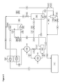
- FIG. 2 shows a schematic diagram of a system of cooling, particularly re-liquefying, boil off gas from a liquefied cargo in a floating transportation vessel in accordance with this disclosure
- FIG. 3 shows a schematic diagram of a system for cooling, particularly re-liquefying, boil off gas from a liquefied cargo in a floating transportation vessel in accordance with this disclosure
- FIG. 4 shows a schematic diagram of a system for cooling, particularly re-liquefying, boil off gas from a liquefied cargo in a floating transportation vessel in accordance with this disclosure
- FIG. 5 shows a schematic diagram of refrigeration capacity versus the concentration of ethane in mol % of a liquefied cargo, in which the balance is provided by propane, for liquefaction systems comprising 2 and 3 stages of compression, compared to the corresponding systems in accordance with this disclosure;
- FIG. 6 shows a schematic diagram of a system for cooling, particularly re-liquefying, boil off gas from a liquefied cargo in a floating transportation vessel in accordance with this disclosure.
- LPG vapour also known as boil off gas
- a compressor in which it is compressed such that the compressed vapour can be cooled and condensed using sea water as the heat sink/refrigerant.
- lighter components of the compressed vapour which cannot be condensed against sea water are usually vented to the atmosphere or recycled to the storage tanks in vapour form.
- the LPG is kept in the storage tank under one or both of reduced temperature (versus ambient) and increased pressure (versus atmospheric).
- FIG. 1 shows a schematic diagram of a known system for re-liquefying boil off gas in a LPG carrier vessel.
- Liquefied petroleum gas LPG
- LPG Liquefied petroleum gas
- a tank 50 which may be insulated and/or pressurized in order to maintain the petroleum gas in a liquefied state. Vaporization of the LPG in the tank, for instance due to imperfect thermal insulation, will result in the formation of petroleum gas in the overhead space of the tank 50 .
- it is removed from the tank 50 as a boil off gas stream 01 .
- As many of the components as possible of the removed boil off gas are normally compressed and cooled, to condense them before it is returned to the tank 50 .
- the boil off gas stream 01 can be passed to a compression system 60 , such as the two stage compressor shown in FIG. 1 which comprises a first compression stage 65 and a second compression stage 75 .
- the two-stage compressor 60 produces a compressed BOG discharge stream 06 which can be passed to a condenser 100 , in which the compressed BOG discharge stream 06 is cooled against seawater.
- the condenser 100 produces a cooled compressed discharge stream 07 and a warmed seawater stream (not shown).
- the cooled compressed discharge stream 07 is a condensed stream comprising those components of the boil off gas capable, at the outlet pressure of the second stage of compression 75 , of re-liquefaction against seawater.
- the non-condensed components which are incapable of re-liquefaction against seawater are removed from the condenser 100 as a cooled vent stream 51 , which is a vapour stream.
- the cooled vent stream of non-condensed components can be vented to the atmosphere, after expansion to atmospheric pressure, via atmospheric vent stream 49 .
- the cooled compressed discharge stream 07 can be passed to a first discharge stream pressure reduction device 120 , such as an expander or Joule-Thomson valve, where it is expanded to provide an expanded cooled discharge stream 17 .
- the expanded cooled discharge stream 17 can then be passed to a first stage heat exchanger 80 , to provide a cooled return fluid stream 18 , which is typically a fully condensed stream.
- the cooled return fluid stream 18 may then be passed to a return pressure reduction device 22 , such as an expander or Joule-Thomson valve, to provide an expanded cooled return fluid stream 24 .
- a return pressure reduction device 22 will reduce the pressure of the cooled return fluid stream 18 from at or near the pressure of the first intermediate compressed BOG stream 02 to a pressure close to that of the LPG and BOG in the tank 50 , such as a pressure just above that of the BOG in the tank which is sufficient to ensure an adequate flow of the expanded cooled return fluid stream 24 to the tank 50 .
- the pressure of the expanded cooled return fluid stream 24 is below that of the discharge pressure of the first stage 65 of compression.
- the expanded cooled return fluid stream 24 can be heat exchanged with the cooled vent stream 51 in heat exchanger 25 to provide a heat exchanged return fluid stream 26 .
- the heat exchange may be sufficient to condense components of the cooled vent stream 51 to provide a condensed vent stream 29 and a non-condensed vent stream 27 .
- the non-condensed vent stream 27 can be expanded to ambient pressure and vented to the atmosphere.
- the condensed vent stream 29 can be added to the heat exchanged return fluid stream 26 to provide a combined heat exchanged return fluid stream 26 a which can be passed to storage tank 50 .
- the first stage 65 of compression provides a first intermediate compressed BOG stream 02 , which is passed to first stage heat exchanger 80 .
- the first intermediate compressed BOG stream 02 can be heat exchanged against the expanded cooled discharge stream 17 in the first stage heat exchanger 80 to provide a cooled first intermediate compressed BOG stream 03 , which is a vapour stream.
- the first discharge stream pressure reduction device 120 should reduce the pressure of the cooled compressed discharge stream 17 to at or near that of the first intermediate compressed BOG stream 02 .
- the cooled compressed discharge stream 17 and the first intermediate compressed BOG stream 02 are mixed in the shell side of the first stage heat exchanger 80 .
- the cooled first intermediate compressed BOG stream 03 can then be passed to the suction of the second stage 75 of compression.
- the second stage 75 compresses the cooled first intermediate compressed BOG stream 03 to provide the compressed BOG discharge stream 06 .
- the method and apparatus disclosed herein seeks to provide an improved method and apparatus of re-liquefying BOG.
- An embodiment of the method and apparatus according to the present disclosure is given in FIG. 2 . Where appropriate, identical stream and component names and reference numerals to that of FIG. 1 have been used for corresponding streams and components in the remaining Figures.
- FIG. 2 shows a liquefied cargo storage tank 50 in a floating transportation vessel, such as an LPG carrier.
- the liquefied cargo may be LPG and the boil off gas may be petroleum gas.
- the petroleum gas may comprise propane and ethane.
- a boil off gas stream 01 comprising evaporated cargo, is passed to a compression system 60 having two or more stages of compression.
- the boil off gas stream 01 may have a pressure (the “BOG pressure”) in the range of from above 0 to 500 kPa gauge.
- the compression system 60 may be a multi-stage compressor comprising two or more stages. By “multi-stage compressor” it is meant that each compression stage in the compressor is driven by the same drive shaft. Alternatively, the compression system 60 may comprise independently driven compressors for each of the stages of compression. When the compression system 60 is a multi-stage compressor, it is typically a reciprocating compressor.
- FIG. 2 shows a compression system 60 having a first stage 65 and a second stage 75 , which is the final stage of compression, although the method and apparatus described herein is also applicable to compressors having three or more stages.
- the first stage 65 and second stage 75 of compression provide low and high pressure streams respectively at their discharge.
- the compression system 60 compresses the boil off gas stream 01 to provide a compressed BOG discharge stream 06 .
- the compressed BOG discharge stream 06 may have a pressure (the “final stage pressure”) in the range of from 1.5 to 2.5 MPa.
- the compressed BOG discharge stream 06 can be passed to a discharge stream heat exchanger 200 , such as a condenser.
- the compressed BOG discharge stream 06 is cooled against a heat exchange fluid, such as seawater, to provide a cooled compressed discharge stream 07 and warmed heat exchange fluid (not shown).
- the seawater used as the heat exchange fluid would have a temperature of +36° C. or below, more typically +32° C. or below.
- the cooled compressed discharge stream 07 is typically a partially, more typically a fully condensed, compressed discharge stream.
- the cooled compressed discharge stream 07 comprises those components of the boil off gas which can be condensed against the heat exchange fluid at the discharge pressure of the final stage of compression.
- the discharge stream heat exchanger 200 is a shell and tube heat exchanger
- the non-condensed components of the compressed BOG discharge stream 06 can exit the heat exchanger as cooled vent stream 51 .
- Cooled vent stream 51 is typically a gaseous stream comprising those components of the boil off gas which cannot be condensed against the heat exchange fluid at the discharge pressure of the final stage of compression.
- the cooled compressed discharge stream 07 is typically passed to a discharge receiver 205 before being discharged as cooled compressed BOG stream 08 .
- Discharge receiver 205 may be an accumulator and can operate to maintain a liquid seal in the discharge heat exchanger 200 and/or maintain the discharge pressure at the final stage 75 of compression.
- the cooled vent stream may be produced by discharge receiver 205 , rather than the discharge heat exchanger 200 . This would occur, for instance, if the discharge heat exchanger was of a type which could not adequately separate vapour and condensed phases into separate streams, such as a plate-type heat exchanger. Such a line-up is shown in the embodiment of FIG. 6 .
- the cooled compressed BOG stream 08 is typically further cooled. This can be achieved by passing the cooled compressed BOG stream 08 to one or more further heat exchangers 180 . Further heat exchanger 180 may be of any type, and an intermediate stage, particularly first stage, economizer for cooling the intermediate BOG streams as well as the cooled compressed stream 08 is shown in FIG. 2 . This is discussed in more detail below.
- the cooled vent stream 51 can be passed to a vent heat exchanger 190 , where it is heat exchanged against a portion of the cooled compressed BOG stream 08 .
- a first discharge stream splitting device 110 divides the cooled compressed BOG stream 08 into a continuing cooled compressed discharge stream 08 a and a cooled compressed BOG side stream 31 .
- the cooled compressed BOG side stream 31 can be passed to a first discharge stream pressure reduction device 120 , such as an expander or Joule-Thomson valve, where it is expanded to provide an expanded cooled BOG stream 33 , which can then be heat exchanged against the cooled vent stream 51 to provide a further cooled vent stream 53 and a BOG recycle stream 35 .
- this heat exchange is carried out by injecting the expanded cooled BOG stream 33 into the shell side of the vent heat exchanger 190 , with the cooled vent stream 51 present in one or more vent heat exchanger coils 195 within the shell of the vent heat exchanger 190 .
- the stream providing the cooling duty to the vent heat exchanger 190 may be drawn as a side stream from the further cooled compressed BOG stream 09 , and then expanded to an intermediate stage pressure, such as the first stage pressure.
- the origin of the further cooled compressed BOG stream 09 is discussed below.
- the first discharge stream splitting device could be provided in the further cooled compressed BOG stream 09 , rather than in the cooled compressed BOG stream 08 .
- the side stream which is then expanded to an intermediate stage pressure would therefore be a further cooled compressed BOG side stream. This can then be expanded to provide an expanded further cooled compressed BOG stream, which can be heat exchanged against the cooled vent stream 51 .
- the BOG recycle stream 35 produced in the vent heat exchanger 190 is typically a vapour stream. It will be apparent that if the cooled compressed BOG side stream 31 is expanded to a pressure at or slightly above that provided by the discharge of the first stage 65 of compression, namely the first stage pressure, then the BOG recycle stream 35 produced from the heat exchange of the expanded cooled compressed BOG stream 33 can be passed to an intermediate compressed BOG stream linking the first and second stages of compression, such as the first intermediate compressed BOG stream 03 a . By passing the BOG recycle stream 35 to the compression system 60 , this stream can be recompressed and cooled, typically condensed, as part of the method described herein. Thus, the further cooling of the cooled vent stream is achieved without an increase in boil off gas vapour being returned to the cargo storage tank 50 .
- the further cooling of the cooled vent stream 51 in the vent heat exchanger 190 can condense a portion of the components of the boil off gas which could not be condensed in the discharge heat exchanger 200 against the heat exchange fluid such as seawater.
- the further cooled vent stream 53 is typically an at least partly condensed stream.
- the further cooled vent stream 53 can be passed to a vent stream pressure reduction device 61 (dashed line), such as a Joule-Thomson valve or expander, where its pressure is reduced to provide an expanded further cooled vent stream 63 (dashed line).
- the expanded further cooled vent stream 63 may have a pressure at or slightly above the pressure of the liquefied cargo storage tank 50 , so that it can be returned to the tank, for instance by addition to expanded cooled BOG return stream 10 to provide combined expanded cooled BOG return stream 10 a.
- the further cooled vent stream 53 can be passed to a vent stream separator 150 , such as a gas/liquid separator.
- the vent stream separator 150 provides a vent discharge stream 55 , which is typically a vapour stream, and a cooled vent BOG return stream 57 , which is typically a condensed stream, more typically a sub-cooled stream, comprising those components of the boil off gas which were condensed in the vent heat exchanger 190 .
- the pressure of the vent discharge stream 55 may be reduced, for instance to a pressure appropriate for return to the storage tank 50 , for storage elsewhere or for venting.
- the cooled vent BOG return stream 57 may be passed through a vent return stream pressure reduction device 58 , such as a Joule-Thomson valve or expander, to provide an expanded cooled vent BOG return stream 59 .
- the expanded cooled vent BOG return stream 59 is typically a condensed stream.
- the expanded cooled vent BOG return stream 59 can be passed to the storage tank 50 , for instance by addition to the expanded cooled BOG return stream 10 .
- an additional heat exchange step can be carried out to cool the vent discharge stream 55 , for instance to condense one or more components of this stream against an expanded portion of the cooled vent BOG return stream 57 .
- the cooled vent BOG return stream 57 can be passed to a vent return stream pressure reduction device 58 to provide an expanded cooled vent BOG return stream 59 , typically at or just above the pressure of the storage tank 50 .
- the expanded cooled vent BOG return stream 59 can then be passed to a further vent heat exchanger, where it can be heat exchanged, typically indirectly, against the vent discharge stream 55 .
- the expanded cooled vent BOG return stream 59 can be warmed to provide a heat exchanged vent BOG return stream in the further vent heat exchanger.
- the vent discharge stream 55 can be cooled to provide a cooled vent discharge stream and a further vent discharge stream.
- the cooled vent discharge stream is typically a condensed stream comprising one or more condensed components.
- the further vent discharge stream is typically a vapour stream comprising one or more non-condensed components.
- the cooled vent discharge stream and the further vent discharge stream can exit as different streams. If the further vent heat exchanger cannot separate streams of different phases, then the stream resulting from the cooling of the vent discharge stream 55 can be passed to a further vent stream separator, such as a gas/liquid separator, which can produce the cooled vent discharge stream and the further vent discharge stream.
- a further vent stream separator such as a gas/liquid separator
- the pressure of the further vent discharge stream may be reduced, for instance to a pressure appropriate for return to the storage tank 50 , for storage elsewhere or for venting.
- the cooled vent discharge stream can be passed to a further vent stream pressure reduction device, where it can be expanded to provide an expanded cooled vent discharge stream, typically at or just above the pressure of the storage tank 50 .
- the heat exchanged vent BOG return stream and the expanded cooled vent discharge stream can then be passed to storage tank 50 .
- a second discharge stream splitting device 210 divides the continuing cooled compressed BOG stream 08 a into a further continuing cooled compressed BOG stream 08 b and an additional cooled compressed BOG side stream 11 .
- the additional cooled compressed BOG side stream 11 can be passed to an second discharge stream pressure reduction device 220 , such as an expander or Joule-Thomson valve, where it is expanded to provide an additional expanded cooled BOG stream 13 , which can then be heat exchanged against the further continuing compressed BOG stream 08 b to provide a further cooled compressed BOG stream 09 , which may be a sub-cooled stream.
- an second discharge stream pressure reduction device 220 such as an expander or Joule-Thomson valve
- the first further heat exchanger 180 may be a shell and tube or shell and coil heat exchanger in which the further continuing cooled compressed BOG stream 08 b is passed through one or more first further heat exchanger tubes or coils 185 (coils are shown in FIG. 2 ) in which it is cooled against the additional expanded cooled BOG stream 13 injected into the shell side of the first heat exchanger.
- the additional cooled compressed BOG side stream 11 can be expanded to a pressure close to the pressure of the discharge of the first stage of the multi-stage compressor.
- the second discharge stream splitting device 210 can be provided downstream of the first further heat exchanger 180 , such that the fluid providing the cooling duty in the first further heat exchanger 180 is obtained by the expansion of a portion of the further cooled compressed BOG stream 09 , rather than the expansion of a portion of the continuing cooled compressed BOG stream 08 a.
- the further cooled compressed BOG stream 09 can then be passed to a return BOG pressure reduction device 130 , such as an expander or Joule-Thomson valve, to provide an expanded cooled BOG return stream 10 , which may be a sub-cooled condensed BOG return stream. This can then be returned to the storage tank 50 .
- a return BOG pressure reduction device 130 such as an expander or Joule-Thomson valve
- first further heat exchanger 180 can also cool intermediate compressed streams from the first compressor stage 65 .
- the first further heat exchanger 180 can be an economizer. This heat exchange can lead to an increased coefficient of performance.
- the boil off gas stream 01 can be compressed by first stage 65 to a first intermediate compressed BOG stream 02 at a first stage pressure.
- the first intermediate compressed BOG stream 02 can then be heat exchanged against the additional expanded further cooled BOG stream 13 to provide a cooled first intermediate compressed BOG stream 03 a .
- This heat exchange can be carried out in first further heat exchanger 180 , which is typically a first intermediate stage economizer.
- first intermediate stage economizer is of the shell and tube type
- the first intermediate compressed BOG stream 02 and the additional expanded further cooled BOG side stream 13 can both be injected into the shell-side of the heat exchanger. This is known as liquid sub-cooling.
- the BOG recycle stream 35 from the vent heat exchanger 190 can be added to the cooled first intermediate compressed BOG stream 03 a to provide a combined cooled first intermediate compressed BOG stream 03 b .
- the combined cooled first intermediate compressed BOG stream 03 b can then be passed to the suction of the second and final stage 75 of the compression system 60 , where it is compressed to provide the compressed BOG discharge stream 06 at a second, and in this embodiment final stage, pressure.
- the first intermediate compressed BOG stream 02 can be passed to the vent heat exchanger 190 .
- This can provide a different split of cooling duty between the first further heat exchanger 180 and the vent heat exchanger 190 .
- the first intermediate compressed BOG stream would be heat exchanged with the expanded cooled BOG stream 33 , and the combined stream produced would be a cooled first intermediate compressed BOG stream, which could be passed to the suction of the second stage 75 of compression.
- the first further heat exchanger rather than producing a cooled first intermediate compressed BOG stream, would produce an overhead expanded cooled discharge stream, which could also be passed to the suction of the second stage 75 of compression, for instance by adding it to the cooled first intermediate compressed BOG stream.
- a flash liquid sub-cooling process may be used.
- the discharge vapour from the first compressor stage is not passed through the first further heat exchanger, but is mixed with the vapour produced in the heat exchanger at or before the suction to the next stage of the compression cycle.
- the first intermediate compressed BOG stream 02 is not passed through the first further heat exchanger 180 as it is in the embodiment of FIG. 2 , but is heat exchanged with the stream, such as an overhead expanded cooled discharge stream, which is typically a vapour stream, produced in the first further heat exchanger 180 from the additional expanded cooled BOG stream 13 .
- This heat exchange can be achieved by mixing the two streams and should occur at or before the suction to the second stage 75 of the compression cycle.
- FIG. 3 shows a further embodiment of the method and apparatus disclosed herein.
- the compression system 60 comprises two stages of compression, a first stage 65 and a second stage 75 which is a final stage, in a similar manner to the embodiment of FIG. 3 .
- the first and second stages 65 and 75 may be two stages of a multi-stage compressor.
- FIG. 3 differs from that of FIG. 2 in that the two heat exchangers 180 , 190 have been combined into a single vent heat exchanger 190 ′. Reducing the number of heat exchangers in the cooling apparatus may be beneficial because of the limited availability of space on the vessel.
- the cooled compressed BOG stream 08 is provided in an identical manner to the embodiment of FIG. 2 . It is passed to a first discharge stream splitting device 110 where it is split into a continuing cooled compressed BOG stream 08 a and a cooled compressed BOG side stream 31 .
- the cooled compressed BOG side stream 31 can be passed to a first discharge stream pressure reduction device 120 , such as an expander or Joule-Thomson valve, where it is expanded to provide an expanded cooled BOG stream 33 .
- the expanded cooled BOG stream 33 can then be heat exchanged against the cooled vent stream 51 , the first intermediate compressed stream 02 and the continuing cooled compressed BOG stream 08 a in the vent heat exchanger 190 ′.
- a shell and coil heat exchanger is shown in the embodiment of FIG. 3 .
- a shell and tube heat exchanger may be used.
- the expanded cooled BOG stream 33 can be injected into the shell side of the vent heat exchanger 190 ′, where it is heat exchanged against (i) the cooled vent stream 51 present in one or more vent heat exchanger coils 195 and (ii) the continuing cooled compressed BOG stream 08 a in one or more compressed BOG stream coils 186 within the shell of the heat exchanger.
- the cooled vent stream 51 and the continuing cooled compressed BOG stream 08 a are therefore maintained separate from the expanded cooled BOG stream 33 .
- the first intermediate compressed stream 02 may also be injected into the shell side of the vent heat exchanger 190 where it can be heat exchanged with the expanded cooled BOG stream 33 , typically by mixing the two fluid streams.
- the cooled vent stream 51 is cooled in the vent heat exchanger 190 ′ to provide a further cooled vent stream 53 .
- further cooling of the cooled vent stream 51 against an expanded portion of the cooled compressed BOG stream is achieved, reducing its temperature below that which could have been achieved by cooling against a heat exchange fluid such as seawater in discharge heat exchanger 200 .
- the further cooled vent stream 53 can be expanded and passed back to the storage tank 50 , or sent to vent stream separator 150 as discussed in the embodiment of FIG. 2 .
- vent heat exchanger 190 ′ can be passed through the return BOG pressure reduction device 130 where it can be expanded to the storage pressure of the storage tank 50 or slightly above this pressure to allow the flow of the expanded cooled return stream 10 to the tank.
- the mixing of the expanded cooled BOG stream 33 with the first intermediate compressed stream 02 in the vent heat exchanger 190 ′ provides a cooled first intermediate compressed stream 03 .
- the cooled first intermediate compressed stream 03 can be passed to the suction of the second stage 75 of compression to provide compressed BOG discharge stream 06 .
- vent heat exchanger 190 ′ functions as an economizer. This provides an efficient way of integrating the various heat exchange processes in a liquid sub-cooling process. However, it is not a requirement of the method and apparatus disclosed herein that heat exchange must be carried out in an economizer. Any heat exchanger or exchangers which facilitate at least the heat exchange of an expanded portion of the cooled compressed BOG stream against the cooled vent stream 51 could be used.
- the expanded cooled BOG stream 33 can be heat exchanged with the cooled vent stream 51 and continuing cooled compressed BOG stream 08 a in the vent heat exchanger 190 ′ in a flash liquid sub-cooling process.
- the stream resulting from the heat exchange of the expanded cooled BOG side stream 33 can be withdrawn from the vent heat exchanger 190 ′ as a BOG recycle stream.
- the BOG recycle stream can then be heat exchanged with the first intermediate compressed BOG stream 02 to provide a cooled first intermediate compressed BOG stream 03 . This can be achieved by adding the BOG recycle stream to the first intermediate compressed BOG stream 02 , thereby mixing the two streams.
- FIG. 4 shows a further embodiment in which the method and apparatus disclosed herein is applied to a compression system 60 comprising three stages of compression, a first stage 65 , a second stage 70 and a third and final stage 75 .
- the first, second and third stages 65 , 70 and 75 produce low, intermediate and high pressure streams respectively.
- the first stage 65 compresses boil off gas stream 01 to provide a first intermediate compressed BOG stream 02 at a first stage pressure.
- the second stage of compression 70 rather than providing compressed BOG discharge stream 06 , provides a second intermediate compressed stream 04 at a second stage pressure.
- the second intermediate compressed stream 04 can be passed to the suction of a third stage 75 of compression.
- Third stage 75 produces a compressed BOG discharge stream 06 which is passed to discharge stream heat exchanger 200 .
- the remaining streams, and their interactions, operate as described for the embodiment of FIG. 2 .
- a portion of the cooled compressed stream 08 can be expanded to the second stage pressure, and heat exchanged against the second intermediate compressed BOG stream 04 to provide a cooled second intermediate compressed stream, which can then be passed to the third stage 75 of compression, and a further cooled compressed stream.
- the heat exchange can be carried out by adding an expanded portion of the cooled compressed stream 08 to the second intermediate compressed stream 04 .
- This heat exchange may be carried out in a second further heat exchanger.
- the second further heat exchanger can also be used to cool one or both of the cooled vent stream 51 and a portion of the cooled compressed BOG stream 08 , to provide a liquid sub-cooling process.
- a portion of the cooled compressed stream 08 can be expanded to the second stage pressure and then heat exchanged against one or both of the cooled vent stream 51 and a portion of the cooled compressed BOG stream 08 in a flash liquid sub-cooling process in a second further heat exchanger.
- the stream resulting from the heat exchange of the expanded cooled BOG stream can then be heat exchanged with the second intermediate compressed BOG stream 04 , for instance by mixing and the combined streams passed to the suction of the third stage 75 as a cooled second intermediate compressed BOG stream.
- FIG. 6 shows a further embodiment of the method and apparatus disclosed herein, disclosing a modification of the embodiment of FIG. 2 .
- the compression system 60 comprises two stages of compression, a first stage 65 and a second stage 75 , which is a final stage, in a similar manner to the embodiment of FIG. 2 .
- the first and second stages 65 and 75 may be two stages of a multi-stage compressor.
- FIG. 6 is particularly advantageous for liquefied cargo comprising lower boiling point components, typically ethane or ethylene, which may be present either as the major component of the liquefied cargo (e.g. that component accounting for the highest proportion in the liquefied cargo by mol %) or as minor component (i.e. in a lesser proportion than the major component).
- lower boiling point components typically ethane or ethylene
- ethane may be present as a minor component of natural gas liquid cargoes, which may further comprise propane or butane as major components.
- Ethylene may be present as the major component in ethylene cargoes, which, if of polymer grade may comprise at least 99.9 mol %, more typically at least 99.95 mol % ethylene, with the balance being impurities such as nitrogen.
- Ethylene has a boiling point below ⁇ 103° C. at a pressure of 1 atmosphere, considerably lower than a petroleum gas such as propane. Consequently, the re-liquefaction of ethylene BOG requires, compared to the re-liquefaction of a propane BOG, a higher discharge pressure at the final stage of compression and/or a heat exchange fluid stream capable of providing a lower temperature than seawater.
- the provision of a higher discharge pressure at the final stage of compression would typically require three or more stages of compression.
- the present embodiment is beneficial because it can provide a reduction in the quantity of valuable cargo which is not re-liquefied and remains in the vent discharge stream 55 , even when only two stages of compression are utilized.
- the compressed BOG discharge stream 06 is provided in an identical manner to the embodiment of FIG. 2 .
- the compressed BOG discharge stream 06 is provided at the discharge of compression system 60 .
- the compressed BOG discharge stream 06 can be passed to a discharge stream heat exchanger 200 .
- the compressed BOG discharge steam 06 can be cooled against a first heat exchange fluid (not shown), such as seawater, in discharge heat exchanger 200 to provide a heat exchanged compressed discharge stream 41 .
- seawater is used as the first heat exchange fluid.
- the seawater may have a temperature of +36° C. or below, more typically +32° C. or below.
- the stream exiting the discharge stream heat exchanger 200 is typically an uncondensed stream, such as an uncondensed ethylene stream, rather than a partially or fully condensed stream.
- the first heat exchange fluid is seawater, it is difficult to provide sufficient cooling duty to condense the compressed BOG discharge stream 06 at the discharge pressure of second stage 75 of the compression system 60 . Consequently, a further heat exchange step can be carried out to provide cooled compressed discharge stream 07 , typically as a partially, more typically as a fully condensed, compressed discharge stream.
- the heat exchanged compressed discharge stream 41 can be cooled against a second heat exchange fluid, in a second heat exchange fluid heat exchanger 203 , to provide the cooled compressed discharge stream 07 .
- the second heat exchange fluid may be a refrigerant, such as propylene or propane, ammonia or refrigerant blends such as R-404A.
- the second heat exchange fluid may be at a temperature of ⁇ 42° C. or below, prior to the heat exchange with the heat exchanged compressed discharge stream 41 .
- the refrigerant may be provided by a refrigerant pack (not shown), for instance a refrigerant system comprising refrigerant compressor, refrigerant driver, second heat exchange fluid heat exchanger 203 and refrigerant heat exchanger, such as a refrigerant condenser.
- the refrigerant may be cooled, typically condensed, against sea water in the refrigerant heat exchanger.
- the refrigerant system is typically a closed refrigerant system.
- a cargo is not used as the refrigerant i.e. the refrigerant system does not comprise a cargo re-liquefaction system.
- the compressed BOG discharge stream 06 can be at least partially, typically fully condensed in compressed discharge stream heat exchanger 200 , to directly provide cooled compressed discharge stream 07 .
- the first heat exchange fluid is a refrigerant, such as propane or propylene.
- the refrigerant system would have to be sized to provide a sufficient cooling duty to the compressed BOG discharge stream 06 without the seawater pre-cooling, particularly de-superheating, of the embodiment of FIG. 6 .
- the cooled compressed discharge stream 07 is typically passed to a discharge receiver 205 before exiting as cooled compressed BOG stream 08 .
- Discharge receiver 205 may be an accumulator and can operate to maintain a liquid seal in the second heat exchange fluid heat exchanger 203 and/or maintain the discharge pressure at the final stage 75 of compression.
- cooled compressed discharge stream 07 which are not condensed by the heat exchange steps can be separated from the condensed components and withdrawn as cooled vent stream 51 b .
- the cooled vent stream 51 b can be drawn from discharge receiver 205 . This would occur, for instance, if the second heat exchange fluid heat exchanger 203 is of a type which could not adequately separate vapour and condensed phases into separate streams, such as a plate-type heat exchanger.
- the cooled vent stream 51 b can then be treated in a similar manner to the cooled vent stream 51 of the embodiment of FIG. 2 .
- the non-condensed components can be separated from the condensed components within the heat exchanger to provide the cooled vent stream directly from the second heat exchange fluid heat exchanger.
- FIG. 6 further shows a second heat exchanger bypass stream 43 , downstream of a second heat exchanger bypass pressure reduction device 45 , typically a control valve.
- Second heat exchanger bypass stream 43 passes the first heat exchanged discharge stream 41 directly to the discharge receiver 205 .
- the bypass stream can be used during the start-up of the cooling method and apparatus.
- FIG. 6 further shows the presence of a BOG recycle stream pressure regulating device 140 in BOG recycle stream 35 , exiting vent heat exchanger 190 .
- the BOG recycle stream pressure regulating device 140 allows the regulation of the pressure within the vent heat exchanger 190 .
- the temperature of the expanded cooled BOG stream 33 can be controlled, thereby controlling the temperature of the further cooled vent stream 53 produced by heat exchanging the expanded cooled BOG stream 33 against the cooled vent stream 51 b .
- the temperature of the further cooled vent stream 53 can determine the relative proportion of its components which are separated into the vent discharge stream 55 and the cooled vent BOG return stream 57 , produced by passing further cooled vent stream 53 to vent stream separator 150 .
- Nitrogen may be present in BOG, because it was present in the liquefied cargo, and/or because it was present in the storage tank or pipework as a residue from an inerting process carried out prior to the loading.
- the method of this embodiment may advantageously reject a disproportionally high amount of nitrogen, compared to that of the valuable cargo components, such as ethane or ethylene, in the vent discharge stream 55 .
- the example examines the advantages of the method disclosed herein for both two-stage and three-stage compressors. Hypothetical calculations of the refrigeration capacity versus ethane content of a liquefied propane cargo were carried out in a system whereby cooled vent streams of non-condensed components from a discharge heat exchanger are cooled against a portion of the cooled compressed BOG stream expanded to the first stage pressure, thereby reducing or eliminating the necessity to recycle non-condensed components back to the cargo storage tanks or to vent same to atmosphere.
- Compression system data was based on two-stage and three-stage compressors supplied by Burckhardt Compression AG of Winterthur, Switzerland.
- the equilibrium vapour compositions corresponding to the liquid phase compositions indicated in the example were calculated using the Peng Robinson Stryjek-Vera equations of state.
- the results of the analysis are shown in FIG. 5 .
- the vertical lines indicated as “2 stage limit” and “3 stage limit” relate to the mechanical limits of the respective compressors in terms of the maximum final discharge pressure relative to the pressure required to effect cooling and/or condensation of the equilibrium vapour corresponding to the liquid phase composition at a condensing temperature of +40° C.
- This condensing temperature is obtainable using seawater at +32° C. as a heat exchange fluid.
- the 2 stage compressor has a mechanical limit, equivalent to a discharge pressure of 20 bar absolute, that equates to a liquid phase composition of around 3.5 mole % ethane. At or below this composition, the 2 stage compressor can compress the equilibrium vapour such that it can be fully condensed.
- the curve indicated as “2 stage” and denoted by the symbol ⁇ represents the effective reduction in capacity of the re-liquefaction system due to the recycling or venting of non-condensed vapour.
- the curve indicated as “2 stage+invention” and denoted by the symbol ⁇ containing an “x” represents the increased vapour phase composition that can be handled by the same re-liquefaction system with the method disclosed herein incorporated.
- the area between the curves is representative of the increased range of operation in respect of percentage ethane in the liquid phase that can be handled with a two-stage compressor operating under the method disclosed herein, obviating the need to install a three-stage compressor.
- the three-stage compressor has a mechanical limit that equates to a liquid phase composition of around 10.0 mole % ethane. At or below this composition, the three-stage compressor can compress the equilibrium vapour such that it can be fully condensed.
- the curve indicated as “3 stage” and denoted by the symbol ⁇ represents the effective reduction in capacity of the re-liquefaction system, particularly at ethane concentrations beyond 6.0 mole %, due to the recycling or venting of non-condensed vapour.
- the curve indicated as “3 stage+invention” and denoted by the symbol ⁇ represents the increased vapour phase composition that can be handled by the same re-liquefaction system with the method disclosed herein incorporated.
- the area between the curves is representative of the increased range of operation in respect of percentage ethane in the liquid phase that can be handled with a three-stage compressor operating under the method disclosed herein, obviating the need to install a four-stage compressor.
Landscapes
- Engineering & Computer Science (AREA)
- Mechanical Engineering (AREA)
- General Engineering & Computer Science (AREA)
- Physics & Mathematics (AREA)
- Thermal Sciences (AREA)
- Chemical & Material Sciences (AREA)
- Chemical Kinetics & Catalysis (AREA)
- General Chemical & Material Sciences (AREA)
- Oil, Petroleum & Natural Gas (AREA)
- Ocean & Marine Engineering (AREA)
- Filling Or Discharging Of Gas Storage Vessels (AREA)
- Separation By Low-Temperature Treatments (AREA)
Abstract
Description
-
- compressing a boil off gas stream from said liquefied cargo in two or more stages of compression comprising at least a first stage and a final stage to provide a compressed BOG discharge stream, wherein said first stage of compression has a first stage discharge pressure and said final stage of compression has a final stage suction pressure and one or more intermediate, optionally cooled, compressed BOG streams are provided between consecutive stages of compression;
- cooling the compressed BOG discharge stream to provide a cooled vent stream and a cooled compressed BOG stream;
- expanding, optionally after further cooling, a portion of the cooled compressed BOG stream to a pressure between that of the first stage discharge pressure and the final stage suction pressure to provide an expanded cooled BOG stream;
- heat exchanging the expanded cooled BOG stream against the cooled vent stream to provide a further cooled vent stream.
-
- adding the BOG recycle stream to an intermediate, optionally cooled, compressed BOG stream.
-
- drawing a portion of the cooled compressed BOG stream to provide a cooled compressed BOG side stream;
- expanding the cooled compressed BOG side stream to provide an expanded cooled BOG stream;
- heat exchanging the expanded cooled BOG stream against the cooled vent stream to provide the further cooled vent stream.
-
- heat exchanging the expanded cooled BOG stream against a portion of the cooled compressed BOG stream to provide a further cooled compressed BOG stream.
-
- compressing the boil off gas stream in the first stage of compression to provide a first intermediate compressed BOG stream as an intermediate compressed BOG stream;
- heat exchanging the expanded cooled BOG stream with the first intermediate compressed BOG stream to provide a cooled first intermediate compressed BOG stream as an intermediate, cooled, compressed BOG stream;
- passing the cooled first intermediate compressed BOG stream to the suction of a second stage of compression.
-
- compressing the boil off gas stream in the first stage of compression to provide a first intermediate compressed BOG stream as an intermediate compressed BOG stream;
- adding the BOG recycle stream to the first intermediate compressed BOG stream to provide a cooled first intermediate compressed BOG stream as an intermediate, cooled, compressed BOG stream;
- passing the cooled first intermediate compressed BOG stream to the suction of a second stage of compression.
-
- drawing a portion of the cooled compressed BOG stream to provide an additional cooled compressed BOG side stream;
- expanding the additional cooled compressed BOG side stream to provide an additional expanded cooled BOG stream;
- heat exchanging the additional expanded cooled BOG stream against a portion of the cooled compressed BOG stream to provide a further cooled compressed BOG stream.
-
- compressing the boil off gas stream in the first stage of compression to provide a first intermediate compressed BOG stream as an intermediate compressed BOG stream;
- heat exchanging the additional expanded cooled BOG stream with the first intermediate compressed BOG stream to provide a cooled first intermediate compressed BOG stream;
- adding the cooled BOG recycle stream to the cooled first intermediate compressed BOG stream and passing the resulting stream to the suction of a second stage of compression.
-
- compressing the boil off gas stream in the first stage of compression to provide a first intermediate compressed BOG stream as an intermediate compressed BOG stream;
- adding the additional BOG recycle stream to the BOG recycle stream to provide a combined BOG recycle stream;
- heat exchanging the combined BOG recycle stream with the first intermediate compressed BOG stream to provide a cooled first intermediate compressed BOG stream;
- passing the cooled first intermediate compressed BOG stream to the suction of a second stage of compression.
-
- expanding the further cooled vent stream to provide an expanded further cooled vent stream;
- passing the expanded further cooled vent stream to a storage tank.
-
- separating the further cooled vent stream to provide a vent discharge stream and a cooled vent BOG return stream.
-
- expanding the cooled vent BOG return stream to provide an expanded cooled vent BOG return stream;
- passing the expanded cooled vent BOG return stream to a storage tank.
-
- expanding the cooled vent BOG return stream to provide an expanded cooled vent BOG return stream;
- heat exchanging the expanded cooled vent BOG return stream against the vent discharge stream to provide a heat exchanged vent BOG return stream, a cooled vent discharge stream and a further vent discharge stream;
- expanding the cooled vent discharge stream to provide an expanded cooled vent discharge stream;
- passing the heat exchanged vent BOG return stream and the expanded cooled vent discharge stream to a storage tank.
-
- expanding the further cooled compressed BOG stream to provide an expanded cooled BOG return stream;
- passing the expanded cooled BOG return stream to a storage tank.
-
- a compression system to compress a boil off gas stream from a liquefied cargo, said compression system comprising two or more stages of compression comprising at least a first stage and a final stage to provide a compressed BOG discharge stream, wherein intermediate, optionally cooled, compressed BOG streams are provided between consecutive stages of compression,
- a discharge heat exchanger to cool the compressed BOG discharge stream to provide a cooled vent stream and a cooled compressed BOG stream; one or more vent heat exchangers to heat exchange an expanded, optionally further cooled, portion of the cooled compressed BOG stream, against the cooled vent stream to provide a further cooled vent stream.
Claims (18)
Applications Claiming Priority (5)
| Application Number | Priority Date | Filing Date | Title |
|---|---|---|---|
| GB201106611A GB201106611D0 (en) | 2011-04-19 | 2011-04-19 | Method of cooling boil off gas and an apparatus therefor |
| GB1106611.5 | 2011-04-19 | ||
| GB1119013.9 | 2011-11-03 | ||
| GBGB1119013.9A GB201119013D0 (en) | 2011-11-03 | 2011-11-03 | Method of cooling boil off gas and an apparatus thereof |
| PCT/GB2012/050750 WO2012143699A1 (en) | 2011-04-19 | 2012-04-03 | Method of cooling boil off gas and an apparatus therefor |
Publications (2)
| Publication Number | Publication Date |
|---|---|
| US20140102133A1 US20140102133A1 (en) | 2014-04-17 |
| US9823014B2 true US9823014B2 (en) | 2017-11-21 |
Family
ID=45974445
Family Applications (1)
| Application Number | Title | Priority Date | Filing Date |
|---|---|---|---|
| US14/111,639 Active 2033-09-12 US9823014B2 (en) | 2011-04-19 | 2012-04-03 | Method of cooling boil off gas and an apparatus therefor |
Country Status (8)
| Country | Link |
|---|---|
| US (1) | US9823014B2 (en) |
| EP (1) | EP2702311B1 (en) |
| JP (1) | JP6142434B2 (en) |
| KR (1) | KR101590311B1 (en) |
| CN (1) | CN103717959B (en) |
| BR (1) | BR112013026808A2 (en) |
| SG (1) | SG194143A1 (en) |
| WO (1) | WO2012143699A1 (en) |
Cited By (1)
| Publication number | Priority date | Publication date | Assignee | Title |
|---|---|---|---|---|
| WO2022189619A1 (en) * | 2021-03-11 | 2022-09-15 | Tge Marine Gas Engineering Gmbh | Method and apparatus for re-liquefying bog |
Families Citing this family (33)
| Publication number | Priority date | Publication date | Assignee | Title |
|---|---|---|---|---|
| DE102013010414B4 (en) | 2013-06-21 | 2016-05-12 | Tge Marine Gas Engineering Gmbh | Re-liquefaction of boil-off gases |
| KR20150131860A (en) * | 2014-05-16 | 2015-11-25 | 대우조선해양 주식회사 | Fuel Supply System and Method for Supplying Fuel of LPG Carrier |
| GB2535425A (en) * | 2014-07-30 | 2016-08-24 | Liquid Gas Equipment Ltd | LNG bunker vessel |
| GB201414893D0 (en) * | 2014-08-21 | 2014-10-08 | Liquid Gas Equipment Ltd | Method of cooling boil off gas and apparatus therefor |
| CN104482395B (en) * | 2014-11-05 | 2016-05-18 | 中海福建天然气有限责任公司 | A kind of method of BOG while utilizing LNG cold energy to reclaim tank car entrucking |
| CN104613312B (en) * | 2015-02-12 | 2016-07-06 | 安徽省鸿申压缩机有限公司 | Process BOG complete set of equipments and the method adopting this equipment to process BOG |
| CN104713310B (en) * | 2015-03-11 | 2018-01-12 | 新奥科技发展有限公司 | Methane gas recovery system and recycling and control method |
| CN104696700B (en) * | 2015-03-11 | 2018-01-12 | 新奥科技发展有限公司 | methane gas recovery system and recovery method |
| GB2538096A (en) * | 2015-05-07 | 2016-11-09 | Highview Entpr Ltd | Systems and methods for controlling pressure in a cryogenic energy storage system |
| KR102189807B1 (en) | 2016-03-10 | 2020-12-14 | 삼성중공업 주식회사 | Apparatus for retreating boil off gas |
| RU2719607C1 (en) * | 2016-03-31 | 2020-04-21 | Дэу Шипбилдинг Энд Марин Инджиниринг Ко., Лтд. | Ship |
| US20190112008A1 (en) | 2016-03-31 | 2019-04-18 | Daewoo Shipbuilding & Marine Engineering Co., Ltd. | Boil-off gas re-liquefying device and method for ship |
| KR101876974B1 (en) * | 2016-09-29 | 2018-07-10 | 대우조선해양 주식회사 | BOG Re-liquefaction Apparatus and Method for Vessel |
| KR102651473B1 (en) * | 2016-11-15 | 2024-03-27 | 한화오션 주식회사 | Low Temperature Boil-Off Gas Reliquefying System and Method |
| NO344169B1 (en) * | 2018-06-04 | 2019-09-30 | Waertsilae Gas Solutions Norway As | Method and system for storage and transport of liquefied petroleum gases |
| KR20210145202A (en) | 2019-03-27 | 2021-12-01 | 엘지이 아이피 매니지먼트 컴퍼니 리미티드 | Method for cooling boil-off gas and apparatus therefor |
| KR20210008453A (en) | 2019-07-10 | 2021-01-22 | 삼성중공업 주식회사 | Fuel gas treating system in ships |
| KR102584159B1 (en) | 2019-07-11 | 2023-10-05 | 삼성중공업 주식회사 | Fuel gas treating system in ships |
| KR102562100B1 (en) | 2019-07-11 | 2023-08-01 | 삼성중공업 주식회사 | Fuel gas treating system in ships |
| KR102584158B1 (en) | 2019-07-18 | 2023-10-05 | 삼성중공업 주식회사 | Fuel gas treating system in ships |
| KR20210016484A (en) | 2019-08-01 | 2021-02-16 | 삼성중공업 주식회사 | Fuel gas treating system in ships |
| GB201912221D0 (en) | 2019-08-26 | 2019-10-09 | Babcock Ip Man Number One Limited | Method of cooling boil off gas and an apparatus therefor |
| CN115298497A (en) | 2020-04-08 | 2022-11-04 | 克里奥斯塔股份有限公司 | Liquefaction and subcooling system and method |
| US20230258400A1 (en) * | 2020-07-23 | 2023-08-17 | Bechtel Energy Technologies & Solutions, Inc. | Systems and Methods for Utilizing Boil-Off Gas for Supplemental Cooling in Natural Gas Liquefaction Plants |
| KR20220133075A (en) * | 2021-03-24 | 2022-10-04 | 한국조선해양 주식회사 | Boil-off gas re-liquefaction system and ship having the same |
| DE102021001650B4 (en) * | 2021-03-29 | 2022-10-13 | Tge Marine Gas Engineering Gmbh | Method and device for reliquefaction of BOG |
| KR102542651B1 (en) * | 2021-05-11 | 2023-06-14 | 에이치디현대중공업 주식회사 | Boil-off gas re-liquefaction system and ship having the same |
| US12158246B2 (en) * | 2021-08-24 | 2024-12-03 | Messer Industries Usa, Inc. | Depressurization system, apparatus and method for high pressure gas delivery |
| CN115468379A (en) * | 2022-08-29 | 2022-12-13 | 青岛双瑞海洋环境工程股份有限公司 | Marine ammonia vapor reliquefaction system |
| CN117967982A (en) * | 2022-10-25 | 2024-05-03 | 江南造船(集团)有限责任公司 | Method and system for reliquefying boil-off gas from shipping liquid cargo |
| EP4695547A1 (en) | 2023-04-11 | 2026-02-18 | Wärtsilä Gas Solutions Norway AS | A method of and apparatus for reliquefying of boil-off gas stream obtained from liquefied gas in a gas storage of a floating storage unit |
| GB2635309A (en) | 2023-09-14 | 2025-05-14 | Lge Ip Man Company Limited | Method and system for recovering fuel from an engine |
| WO2025190761A1 (en) | 2024-03-13 | 2025-09-18 | Lge Ip Management Company Ltd | Method and system for recovering fuel from an engine |
Citations (23)
| Publication number | Priority date | Publication date | Assignee | Title |
|---|---|---|---|---|
| US3885394A (en) | 1972-12-11 | 1975-05-27 | Sulzer Ag | Process and apparatus for treating and utilizing vaporized gas in a ship for transporting liquified gas |
| GB1472533A (en) | 1973-06-27 | 1977-05-04 | Petrocarbon Dev Ltd | Reliquefaction of boil-off gas from a ships cargo of liquefied natural gas |
| DE3225300A1 (en) | 1982-07-07 | 1984-01-12 | Drago Dipl.-Ing. 5020 Frechen Kober | Refrigerated semipressurised LPG gas tanker |
| US4588427A (en) * | 1985-03-13 | 1986-05-13 | Dm International Inc. | Method and apparatus for purification of high N2 content gas |
| JPS6224799A (en) | 1985-07-25 | 1987-02-02 | Matsushita Electric Works Ltd | Terminal equipment for time division multiplex transmission system |
| JPS62224799A (en) | 1986-03-24 | 1987-10-02 | Tokyo Gas Co Ltd | Treatment method for boil off gas |
| US5036671A (en) | 1990-02-06 | 1991-08-06 | Liquid Air Engineering Company | Method of liquefying natural gas |
| WO1996022221A1 (en) | 1995-01-19 | 1996-07-25 | Sinvent A/S | Recondensation of gaseous hydrocarbons |
| US5979183A (en) | 1998-05-22 | 1999-11-09 | Air Products And Chemicals, Inc. | High availability gas turbine drive for an air separation unit |
| EP1120615A2 (en) | 2000-01-26 | 2001-08-01 | Cryostar-France SA | Apparatus for reliquefying compressed vapour |
| WO2001059377A1 (en) | 2000-02-10 | 2001-08-16 | Sinvent As | Method and device for small scale liquefaction of a product gas |
| CN1335475A (en) | 2000-03-09 | 2002-02-13 | 克里奥斯塔-法兰西有限公司 | Reliquefaction of compressed steam |
| WO2005047761A1 (en) | 2003-11-13 | 2005-05-26 | Hamworthy Kse Gas Systems As | Apparatus and method for controlling temperature in a boil-off gas |
| KR20080031611A (en) | 2007-04-20 | 2008-04-10 | 대우조선해양 주식회사 | Refrigeration system for boil-off gas reliquefaction |
| KR20080081436A (en) | 2007-03-05 | 2008-09-10 | 신영중공업주식회사 | Device and method for liquefaction re-liquefaction |
| JP2008286211A (en) | 2007-05-15 | 2008-11-27 | Ihi Corp | Bog compression installation and its operation method |
| CN101392980A (en) | 2008-10-31 | 2009-03-25 | 华南理工大学 | A kind of reliquefaction method of shipping liquefied ethylene/ethane boil-off gas |
| US20100058802A1 (en) * | 2006-11-01 | 2010-03-11 | Einar Brendeng | Method for liquefaction of gas |
| WO2010093400A1 (en) | 2009-02-11 | 2010-08-19 | Exxonmobil Upstream Research Company | Methods and systems of regenerative heat exchange |
| WO2010108464A2 (en) | 2009-03-27 | 2010-09-30 | Marine Service Gmbh | Method and device for operating a driving engine for a vessel for transporting liquefied petrol gas |
| KR20100108932A (en) | 2009-03-31 | 2010-10-08 | 대우조선해양 주식회사 | Apparatus and method for treating boil-off gas to reduce reliquefaction power consumption |
| WO2011002299A1 (en) | 2009-06-30 | 2011-01-06 | Hamworthy Gas Systems As | Method and system for storage and transport of liquefied petroleum gases |
| US20140123699A1 (en) | 2011-04-06 | 2014-05-08 | Babcock Integrated Technology | Method of cooling boil off gas and an apparatus therefor |
Family Cites Families (2)
| Publication number | Priority date | Publication date | Assignee | Title |
|---|---|---|---|---|
| JPS5177915A (en) * | 1974-12-27 | 1976-07-06 | Kawasaki Heavy Ind Ltd | Teionekikasekyugasu tankusenniokeru boiru ofu gasuno shorihoshiki |
| PE20060221A1 (en) * | 2004-07-12 | 2006-05-03 | Shell Int Research | LIQUEFIED NATURAL GAS TREATMENT |
-
2012
- 2012-04-03 BR BR112013026808A patent/BR112013026808A2/en not_active IP Right Cessation
- 2012-04-03 JP JP2014505710A patent/JP6142434B2/en active Active
- 2012-04-03 KR KR1020137029499A patent/KR101590311B1/en active Active
- 2012-04-03 EP EP12714831.0A patent/EP2702311B1/en active Active
- 2012-04-03 SG SG2013075197A patent/SG194143A1/en unknown
- 2012-04-03 US US14/111,639 patent/US9823014B2/en active Active
- 2012-04-03 CN CN201280029810.9A patent/CN103717959B/en not_active Ceased
- 2012-04-03 WO PCT/GB2012/050750 patent/WO2012143699A1/en not_active Ceased
Patent Citations (26)
| Publication number | Priority date | Publication date | Assignee | Title |
|---|---|---|---|---|
| US3885394A (en) | 1972-12-11 | 1975-05-27 | Sulzer Ag | Process and apparatus for treating and utilizing vaporized gas in a ship for transporting liquified gas |
| GB1401584A (en) | 1972-12-11 | 1975-07-16 | Sulzer Ag | Transportation of liquefied combustible gas by ship |
| GB1472533A (en) | 1973-06-27 | 1977-05-04 | Petrocarbon Dev Ltd | Reliquefaction of boil-off gas from a ships cargo of liquefied natural gas |
| DE3225300A1 (en) | 1982-07-07 | 1984-01-12 | Drago Dipl.-Ing. 5020 Frechen Kober | Refrigerated semipressurised LPG gas tanker |
| US4588427A (en) * | 1985-03-13 | 1986-05-13 | Dm International Inc. | Method and apparatus for purification of high N2 content gas |
| JPS6224799A (en) | 1985-07-25 | 1987-02-02 | Matsushita Electric Works Ltd | Terminal equipment for time division multiplex transmission system |
| JPS62224799A (en) | 1986-03-24 | 1987-10-02 | Tokyo Gas Co Ltd | Treatment method for boil off gas |
| US5036671A (en) | 1990-02-06 | 1991-08-06 | Liquid Air Engineering Company | Method of liquefying natural gas |
| WO1996022221A1 (en) | 1995-01-19 | 1996-07-25 | Sinvent A/S | Recondensation of gaseous hydrocarbons |
| EP0804360A1 (en) | 1995-01-19 | 1997-11-05 | Sinvent A/S | Recondensation of gaseous hydrocarbons |
| US5979183A (en) | 1998-05-22 | 1999-11-09 | Air Products And Chemicals, Inc. | High availability gas turbine drive for an air separation unit |
| EP1120615A2 (en) | 2000-01-26 | 2001-08-01 | Cryostar-France SA | Apparatus for reliquefying compressed vapour |
| WO2001059377A1 (en) | 2000-02-10 | 2001-08-16 | Sinvent As | Method and device for small scale liquefaction of a product gas |
| CN1335475A (en) | 2000-03-09 | 2002-02-13 | 克里奥斯塔-法兰西有限公司 | Reliquefaction of compressed steam |
| WO2005047761A1 (en) | 2003-11-13 | 2005-05-26 | Hamworthy Kse Gas Systems As | Apparatus and method for controlling temperature in a boil-off gas |
| CN1894535A (en) | 2003-11-13 | 2007-01-10 | 哈姆沃西Kse瓦斯系统公司 | Apparatus and method for controlling temperature in a boil-off gas |
| US20100058802A1 (en) * | 2006-11-01 | 2010-03-11 | Einar Brendeng | Method for liquefaction of gas |
| KR20080081436A (en) | 2007-03-05 | 2008-09-10 | 신영중공업주식회사 | Device and method for liquefaction re-liquefaction |
| KR20080031611A (en) | 2007-04-20 | 2008-04-10 | 대우조선해양 주식회사 | Refrigeration system for boil-off gas reliquefaction |
| JP2008286211A (en) | 2007-05-15 | 2008-11-27 | Ihi Corp | Bog compression installation and its operation method |
| CN101392980A (en) | 2008-10-31 | 2009-03-25 | 华南理工大学 | A kind of reliquefaction method of shipping liquefied ethylene/ethane boil-off gas |
| WO2010093400A1 (en) | 2009-02-11 | 2010-08-19 | Exxonmobil Upstream Research Company | Methods and systems of regenerative heat exchange |
| WO2010108464A2 (en) | 2009-03-27 | 2010-09-30 | Marine Service Gmbh | Method and device for operating a driving engine for a vessel for transporting liquefied petrol gas |
| KR20100108932A (en) | 2009-03-31 | 2010-10-08 | 대우조선해양 주식회사 | Apparatus and method for treating boil-off gas to reduce reliquefaction power consumption |
| WO2011002299A1 (en) | 2009-06-30 | 2011-01-06 | Hamworthy Gas Systems As | Method and system for storage and transport of liquefied petroleum gases |
| US20140123699A1 (en) | 2011-04-06 | 2014-05-08 | Babcock Integrated Technology | Method of cooling boil off gas and an apparatus therefor |
Non-Patent Citations (4)
| Title |
|---|
| Liquified Gas Handling Principles on Ships and in Terminals; McGuire & White, Third Edition, copyright 2000 (various pages). |
| Machine Translation of Schmidt-Luessamnn (WO2010/108464). * |
| Nicol, Boris, "International Search Report" for PCT/GB2012/050748, as mailed Jul. 11, 2012, 3 pages. |
| Nicol, Boris, "International Search Report" for PCT/GB2012/050750, as mailed Jul. 11, 2012, 3 pages. |
Cited By (2)
| Publication number | Priority date | Publication date | Assignee | Title |
|---|---|---|---|---|
| WO2022189619A1 (en) * | 2021-03-11 | 2022-09-15 | Tge Marine Gas Engineering Gmbh | Method and apparatus for re-liquefying bog |
| CN116964372A (en) * | 2021-03-11 | 2023-10-27 | 塔格海底天然气工程有限公司 | Methods and equipment for reliquefaction of BOG |
Also Published As
| Publication number | Publication date |
|---|---|
| EP2702311B1 (en) | 2021-06-09 |
| JP6142434B2 (en) | 2017-06-07 |
| JP2014511985A (en) | 2014-05-19 |
| US20140102133A1 (en) | 2014-04-17 |
| CN103717959B (en) | 2015-07-15 |
| SG194143A1 (en) | 2013-11-29 |
| WO2012143699A1 (en) | 2012-10-26 |
| KR101590311B1 (en) | 2016-02-18 |
| KR20140027233A (en) | 2014-03-06 |
| BR112013026808A2 (en) | 2017-01-10 |
| CN103717959A (en) | 2014-04-09 |
| EP2702311A1 (en) | 2014-03-05 |
Similar Documents
| Publication | Publication Date | Title |
|---|---|---|
| US9823014B2 (en) | Method of cooling boil off gas and an apparatus therefor | |
| EP2742276B1 (en) | Method of cooling boil off gas and an apparatus therefor | |
| EP3183489B1 (en) | Method of cooling boil off gas and an apparatus therefor | |
| CN112243479B (en) | Method and system for storage and transportation of liquefied petroleum gas | |
| US12013179B2 (en) | Method of cooling boil off gas and an apparatus therefor | |
| US20220316796A1 (en) | Method Of Cooling Boil Off Gas And An Apparatus Therefor | |
| GB2494627A (en) | Method and apparatus for cooling boil off gas on a ship, barge or floating platform |
Legal Events
| Date | Code | Title | Description |
|---|---|---|---|
| AS | Assignment |
Owner name: LIQUID GAS EQUIPMENT LIMITED, UNITED KINGDOM Free format text: ASSIGNMENT OF ASSIGNORS INTEREST;ASSIGNOR:DUCKETT, ALAN RODERICK;REEL/FRAME:033208/0133 Effective date: 20140528 |
|
| AS | Assignment |
Owner name: BABCOCK IP MANAGEMENT (NUMBER ONE) LIMITED, UNITED Free format text: ASSIGNMENT OF ASSIGNORS INTEREST;ASSIGNOR:LIQUID GAS EQUIPMENT LIMITED;REEL/FRAME:039297/0986 Effective date: 20160629 |
|
| STCF | Information on status: patent grant |
Free format text: PATENTED CASE |
|
| MAFP | Maintenance fee payment |
Free format text: PAYMENT OF MAINTENANCE FEE, 4TH YEAR, LARGE ENTITY (ORIGINAL EVENT CODE: M1551); ENTITY STATUS OF PATENT OWNER: LARGE ENTITY Year of fee payment: 4 |
|
| AS | Assignment |
Owner name: LGE IP MANAGEMENT COMPANY LIMITED, UNITED KINGDOM Free format text: ASSIGNMENT OF ASSIGNORS INTEREST;ASSIGNOR:BABCOCK IP MANAGEMENT (NUMBER ONE) LIMITED;REEL/FRAME:057164/0032 Effective date: 20210703 |
|
| MAFP | Maintenance fee payment |
Free format text: PAYMENT OF MAINTENANCE FEE, 8TH YEAR, LARGE ENTITY (ORIGINAL EVENT CODE: M1552); ENTITY STATUS OF PATENT OWNER: LARGE ENTITY Year of fee payment: 8 |