US9821165B2 - Method for symmetry-based implant control - Google Patents
Method for symmetry-based implant control Download PDFInfo
- Publication number
- US9821165B2 US9821165B2 US15/270,434 US201615270434A US9821165B2 US 9821165 B2 US9821165 B2 US 9821165B2 US 201615270434 A US201615270434 A US 201615270434A US 9821165 B2 US9821165 B2 US 9821165B2
- Authority
- US
- United States
- Prior art keywords
- symmetry
- implant
- detecting
- control unit
- sensor
- Prior art date
- Legal status (The legal status is an assumption and is not a legal conclusion. Google has not performed a legal analysis and makes no representation as to the accuracy of the status listed.)
- Active
Links
Images


Classifications
-
- A—HUMAN NECESSITIES
- A61—MEDICAL OR VETERINARY SCIENCE; HYGIENE
- A61N—ELECTROTHERAPY; MAGNETOTHERAPY; RADIATION THERAPY; ULTRASOUND THERAPY
- A61N1/00—Electrotherapy; Circuits therefor
- A61N1/18—Applying electric currents by contact electrodes
- A61N1/32—Applying electric currents by contact electrodes alternating or intermittent currents
- A61N1/36—Applying electric currents by contact electrodes alternating or intermittent currents for stimulation
- A61N1/3605—Implantable neurostimulators for stimulating central or peripheral nerve system
- A61N1/3606—Implantable neurostimulators for stimulating central or peripheral nerve system adapted for a particular treatment
- A61N1/3611—Respiration control
-
- A61B5/0488—
-
- A—HUMAN NECESSITIES
- A61—MEDICAL OR VETERINARY SCIENCE; HYGIENE
- A61B—DIAGNOSIS; SURGERY; IDENTIFICATION
- A61B5/00—Measuring for diagnostic purposes; Identification of persons
- A61B5/07—Endoradiosondes
- A61B5/076—Permanent implantations
-
- A—HUMAN NECESSITIES
- A61—MEDICAL OR VETERINARY SCIENCE; HYGIENE
- A61B—DIAGNOSIS; SURGERY; IDENTIFICATION
- A61B5/00—Measuring for diagnostic purposes; Identification of persons
- A61B5/08—Detecting, measuring or recording devices for evaluating the respiratory organs
-
- A—HUMAN NECESSITIES
- A61—MEDICAL OR VETERINARY SCIENCE; HYGIENE
- A61B—DIAGNOSIS; SURGERY; IDENTIFICATION
- A61B5/00—Measuring for diagnostic purposes; Identification of persons
- A61B5/24—Detecting, measuring or recording bioelectric or biomagnetic signals of the body or parts thereof
- A61B5/316—Modalities, i.e. specific diagnostic methods
- A61B5/389—Electromyography [EMG]
-
- A—HUMAN NECESSITIES
- A61—MEDICAL OR VETERINARY SCIENCE; HYGIENE
- A61B—DIAGNOSIS; SURGERY; IDENTIFICATION
- A61B5/00—Measuring for diagnostic purposes; Identification of persons
- A61B5/48—Other medical applications
- A61B5/4806—Sleep evaluation
- A61B5/4818—Sleep apnoea
-
- A—HUMAN NECESSITIES
- A61—MEDICAL OR VETERINARY SCIENCE; HYGIENE
- A61B—DIAGNOSIS; SURGERY; IDENTIFICATION
- A61B5/00—Measuring for diagnostic purposes; Identification of persons
- A61B5/48—Other medical applications
- A61B5/4836—Diagnosis combined with treatment in closed-loop systems or methods
-
- A—HUMAN NECESSITIES
- A61—MEDICAL OR VETERINARY SCIENCE; HYGIENE
- A61N—ELECTROTHERAPY; MAGNETOTHERAPY; RADIATION THERAPY; ULTRASOUND THERAPY
- A61N1/00—Electrotherapy; Circuits therefor
- A61N1/02—Details
- A61N1/04—Electrodes
- A61N1/05—Electrodes for implantation or insertion into the body, e.g. heart electrode
- A61N1/0526—Head electrodes
- A61N1/0548—Oral electrodes
-
- A—HUMAN NECESSITIES
- A61—MEDICAL OR VETERINARY SCIENCE; HYGIENE
- A61N—ELECTROTHERAPY; MAGNETOTHERAPY; RADIATION THERAPY; ULTRASOUND THERAPY
- A61N1/00—Electrotherapy; Circuits therefor
- A61N1/18—Applying electric currents by contact electrodes
- A61N1/32—Applying electric currents by contact electrodes alternating or intermittent currents
- A61N1/36—Applying electric currents by contact electrodes alternating or intermittent currents for stimulation
- A61N1/3605—Implantable neurostimulators for stimulating central or peripheral nerve system
- A61N1/36128—Control systems
- A61N1/36135—Control systems using physiological parameters
- A61N1/36139—Control systems using physiological parameters with automatic adjustment
-
- A—HUMAN NECESSITIES
- A61—MEDICAL OR VETERINARY SCIENCE; HYGIENE
- A61N—ELECTROTHERAPY; MAGNETOTHERAPY; RADIATION THERAPY; ULTRASOUND THERAPY
- A61N1/00—Electrotherapy; Circuits therefor
- A61N1/18—Applying electric currents by contact electrodes
- A61N1/32—Applying electric currents by contact electrodes alternating or intermittent currents
- A61N1/36—Applying electric currents by contact electrodes alternating or intermittent currents for stimulation
- A61N1/3605—Implantable neurostimulators for stimulating central or peripheral nerve system
- A61N1/36128—Control systems
- A61N1/36146—Control systems specified by the stimulation parameters
- A61N1/3615—Intensity
- A61N1/36157—Current
-
- A—HUMAN NECESSITIES
- A61—MEDICAL OR VETERINARY SCIENCE; HYGIENE
- A61N—ELECTROTHERAPY; MAGNETOTHERAPY; RADIATION THERAPY; ULTRASOUND THERAPY
- A61N1/00—Electrotherapy; Circuits therefor
- A61N1/18—Applying electric currents by contact electrodes
- A61N1/32—Applying electric currents by contact electrodes alternating or intermittent currents
- A61N1/36—Applying electric currents by contact electrodes alternating or intermittent currents for stimulation
- A61N1/3605—Implantable neurostimulators for stimulating central or peripheral nerve system
- A61N1/36128—Control systems
- A61N1/36146—Control systems specified by the stimulation parameters
- A61N1/36167—Timing, e.g. stimulation onset
- A61N1/36171—Frequency
-
- A—HUMAN NECESSITIES
- A61—MEDICAL OR VETERINARY SCIENCE; HYGIENE
- A61N—ELECTROTHERAPY; MAGNETOTHERAPY; RADIATION THERAPY; ULTRASOUND THERAPY
- A61N1/00—Electrotherapy; Circuits therefor
- A61N1/18—Applying electric currents by contact electrodes
- A61N1/32—Applying electric currents by contact electrodes alternating or intermittent currents
- A61N1/36—Applying electric currents by contact electrodes alternating or intermittent currents for stimulation
- A61N1/372—Arrangements in connection with the implantation of stimulators
- A61N1/37205—Microstimulators, e.g. implantable through a cannula
-
- A—HUMAN NECESSITIES
- A61—MEDICAL OR VETERINARY SCIENCE; HYGIENE
- A61N—ELECTROTHERAPY; MAGNETOTHERAPY; RADIATION THERAPY; ULTRASOUND THERAPY
- A61N1/00—Electrotherapy; Circuits therefor
- A61N1/18—Applying electric currents by contact electrodes
- A61N1/32—Applying electric currents by contact electrodes alternating or intermittent currents
- A61N1/36—Applying electric currents by contact electrodes alternating or intermittent currents for stimulation
- A61N1/372—Arrangements in connection with the implantation of stimulators
- A61N1/375—Constructional arrangements, e.g. casings
- A61N1/3756—Casings with electrodes thereon, e.g. leadless stimulators
-
- A—HUMAN NECESSITIES
- A61—MEDICAL OR VETERINARY SCIENCE; HYGIENE
- A61N—ELECTROTHERAPY; MAGNETOTHERAPY; RADIATION THERAPY; ULTRASOUND THERAPY
- A61N1/00—Electrotherapy; Circuits therefor
- A61N1/18—Applying electric currents by contact electrodes
- A61N1/32—Applying electric currents by contact electrodes alternating or intermittent currents
- A61N1/36—Applying electric currents by contact electrodes alternating or intermittent currents for stimulation
- A61N1/372—Arrangements in connection with the implantation of stimulators
- A61N1/378—Electrical supply
- A61N1/3787—Electrical supply from an external energy source
-
- A—HUMAN NECESSITIES
- A61—MEDICAL OR VETERINARY SCIENCE; HYGIENE
- A61B—DIAGNOSIS; SURGERY; IDENTIFICATION
- A61B5/00—Measuring for diagnostic purposes; Identification of persons
- A61B5/0002—Remote monitoring of patients using telemetry, e.g. transmission of vital signals via a communication network
- A61B5/0031—Implanted circuitry
-
- A—HUMAN NECESSITIES
- A61—MEDICAL OR VETERINARY SCIENCE; HYGIENE
- A61B—DIAGNOSIS; SURGERY; IDENTIFICATION
- A61B5/00—Measuring for diagnostic purposes; Identification of persons
- A61B5/103—Detecting, measuring or recording devices for testing the shape, pattern, colour, size or movement of the body or parts thereof, for diagnostic purposes
- A61B5/11—Measuring movement of the entire body or parts thereof, e.g. head or hand tremor, mobility of a limb
- A61B5/113—Measuring movement of the entire body or parts thereof, e.g. head or hand tremor, mobility of a limb occurring during breathing
Definitions
- Some applications of the present invention generally relate to medical apparatus. More specifically, some applications of the present invention relate to neurostimulator implants, and to apparatus and techniques for use therewith.
- Sleep apnea is a chronic sleep breathing disorder typically characterized by abnormal pauses (apneas) in an individual's breathing, ranging from seconds to minutes in duration, or by instances of abnormally low breathing. Sleep apnea is associated with cardiovascular disease, myocardial infarction, high blood pressure, stroke, arrhythmias, diabetes, sleep-deprived driving accidents, and cerebrovascular disease.
- PAP positive airway pressure
- CPAP continuous positive expiratory pressure
- oral appliances e.g., surgery
- surgery e.g., genioglossus advancement, tongue radiofrequency treatment, midline glossectomy, hyoid suspension and maxillomandibular advancement
- lifestyle changes e.g., positional therapy and weight loss
- implantable muscle stimulators e.g., positional therapy and weight loss
- two implants are implanted in a vicinity of respective hypoglossal nerves of a subject, each implant comprising at least one electrode.
- a breathing sensor is configured to detect a breathing-related factor of a subject.
- a driver is configured to drive each electrode to apply a respective electrical current to a respective hypoglossal nerve.
- Circuitry is configured to calibrate the currents applied by the electrodes in response to a detected symmetry-related factor that is indicative of a degree of symmetry of the subject.
- a symmetry sensor detects the symmetry-related factor.
- the symmetry sensor is extracorporeal.
- the symmetry sensor is implantable.
- the breathing sensor is intracorporeal.
- the breathing sensor is implantable.
- apparatus for use with a body of a subject including:
- a breathing sensor configured to detect a breathing-related factor of the subject
- At least a first electrode configured to be placed in a vicinity of a respective first hypoglossal nerve of the subject, and to be driven, in response to the detected breathing-related factor, to apply a first electrical current to the first hypoglossal nerve;
- At least a second electrode configured to be placed in a vicinity of a respective second hypoglossal nerve of the subject, and to be driven, in response to the detected breathing-related factor, to apply a second electrical current to the second hypoglossal nerve;
- circuitry configured to, in response to a detected symmetry-related factor indicative of a degree of symmetry of the subject, configure at least one current selected from the group consisting of: the first current and the second current.
- the breathing sensor includes exactly one breathing sensor.
- the first electrode and the second electrode are configured to be placed by being injected into the subject.
- the circuitry is further configured to configure at least the first electrical current to initiate action potentials in the first hypoglossal nerve without directly initiating contraction of muscle of the subject.
- the circuitry is further configured to configure at least the first electrical current to have a frequency of between 10 and 40 Hz.
- the circuitry is further configured to configure at least the first electrical current to have an amplitude of between 0.1 and 3 mA.
- the apparatus further includes at least one driver, configured to drive at least one electrode selected from the group consisting of: the at least first electrode and the at least second electrode.
- the at least one driver includes exactly one driver, configured to wirelessly drive the at least first electrode and the at least second electrode.
- the at least one driver includes (1) a first driver, coupled to the at least first electrode, and configured to drive the at least first electrode, and (2) a second driver, coupled to the at least second electrode, and configured to drive the at least second electrode.
- the apparatus further includes a symmetry sensor, configured to detect the symmetry-related factor.
- the symmetry sensor is configured to detect a mechanical symmetry of the subject.
- the symmetry sensor includes an accelerometer.
- the symmetry sensor is configured to detect an electrical symmetry of the subject.
- the symmetry sensor includes an electrode.
- the electrode includes an electromyographic electrode.
- the apparatus further includes an extracorporeal control unit that includes the symmetry sensor, and is configured to transmit a wireless signal at least in part responsively to the detected symmetry-related factor.
- the extracorporeal control unit further includes the breathing sensor.
- the circuitry is configured to receive the wireless signal, and to configure the at least one selected current in response to receiving the wireless signal.
- the extracorporeal control unit is configured to provide power wirelessly to the circuitry.
- the circuitry includes a first circuitry configured to configure the first current in response to the detected symmetry-related factor
- the apparatus further includes:
- a first implant configured to be implanted in the vicinity of the first hypoglossal nerve, and including the first electrode and the first circuitry;
- a second implant configured to be implanted in the vicinity of the second hypoglossal nerve, and including the second electrode and second circuitry configured to configure the second current in response to the detected symmetry-related factor.
- the apparatus further includes a control unit, including a symmetry sensor, configured to detect the symmetry-related factor, to transmit a wireless signal at least in part responsively to the detected symmetry-related factor, and to configure the wireless signal to independently address the first implant and the second implant.
- a control unit including a symmetry sensor, configured to detect the symmetry-related factor, to transmit a wireless signal at least in part responsively to the detected symmetry-related factor, and to configure the wireless signal to independently address the first implant and the second implant.
- At least one implant selected from the group consisting of: the first implant and the second implant includes the breathing sensor.
- At least one implant selected from the group consisting of: the first implant and the second implant includes a symmetry sensor, configured to detect the symmetry-related factor.
- the apparatus further includes a control unit, including the circuitry, and configured to configure at least the at least one selected current in response to the detected symmetry-related factor.
- control unit includes an implantable control unit implantable in the body of the subject.
- control unit includes the breathing sensor.
- control unit includes exactly one control unit, and is configured to configure the first current and the second current in response to the detected symmetry-related factor.
- control unit includes an extracorporeal control unit.
- control unit includes a symmetry sensor, configured to detect the symmetry-related factor.
- control unit is configured to configure at least the at least one selected current by transmitting a wireless signal in response to detecting the symmetry-related factor.
- a method for use with a body of a subject including:
- the method further includes configuring at least the first electrical current to initiate action potentials in the first hypoglossal nerve without directly initiating contraction of muscle of the subject.
- detecting the breathing-related factor includes extracorporeally detecting the breathing-related factor.
- the method further includes detecting the symmetry-related factor.
- detecting the symmetry-related factor includes detecting a mechanical symmetry of the subject.
- detecting the symmetry-related factor includes detecting an electrical symmetry of the subject.
- detecting the symmetry-related factor includes detecting an electromyographic factor of the subject.
- detecting the symmetry-related factor includes extracorporeally detecting the symmetry-related factor.
- the method further includes transmitting a wireless signal at least in part responsively to the detected symmetry-related factor.
- the method further includes intracorporeally receiving the wireless signal, and configuring the at least one selected current in response to receiving the wireless signal.
- the method further includes extracorporeally transmitting wireless power, and intracorporeally receiving the wireless power.
- configuring the at least one selected current includes configuring the first current and the second current.
- the method further includes transmitting a wireless signal at least in part responsively to the detected symmetry-related factor, and configuring the wireless signal to (1) induce the configuring of the first current, and (2) induce the configuring of the second current independently of the inducing of the configuring of the first current.
- detecting the breathing-related parameter includes detecting the breathing-related parameter using a breathing sensor
- applying the first electrical current includes applying the first electrical current using a first electrode disposed in a vicinity of the first hypoglossal nerve;
- applying the second electrical current includes applying the second electrical current using a second electrode disposed in a vicinity of the second hypoglossal nerve;
- configuring the at least one selected current includes configuring the at least one selected current using circuitry configured to configure the at least one selected current in response to the detected symmetry-related factor.
- applying the first electrical current includes applying the first electrical current using a first electrode that has been injected into the subject.
- the method further includes detecting the symmetry-related factor using a symmetry sensor.
- detecting the symmetry-related factor includes detecting a mechanical symmetry of the subject.
- detecting the symmetry-related factor includes detecting the symmetry-related factor using a symmetry sensor that includes an accelerometer.
- detecting the symmetry-related factor includes detecting an electrical symmetry of the subject.
- detecting the symmetry-related factor includes detecting the symmetry-related factor using a symmetry sensor that includes an electrode.
- detecting the symmetry-related factor includes detecting the symmetry-related factor using a symmetry sensor that includes an electromyographic electrode.
- detecting the symmetry-related factor includes detecting the symmetry-related factor using an extracorporeal control unit that includes the symmetry sensor, and
- the method further includes transmitting a wireless signal at least in part responsively to the detected symmetry-related factor.
- detecting the breathing-related factor includes detecting the breathing-related factor using the extracorporeal control unit, the extracorporeal control unit including the breathing sensor.
- the method further includes receiving the wireless signal using the circuitry.
- the method further includes providing power wirelessly to the circuitry using the extracorporeal control unit.
- the circuitry includes a first circuitry
- a first implant includes the first circuitry and the first electrode
- applying the first current includes applying the first current using the first electrode of the first implant,
- a second implant includes the second electrode and second circuitry
- applying the second current includes applying the second current using the second electrode of the second implant, and
- configuring the at least one selected current includes:
- the method further includes:
- At least one implant selected from the group consisting of: the first implant and the second implant includes the breathing sensor, and detecting the breathing-related factor includes detecting the breathing-related factor using the breathing sensor of the at least one selected implant.
- At least one implant selected from the group consisting of: the first implant and the second implant includes a symmetry sensor
- the method further includes detecting the symmetry-related factor using the symmetry sensor of the at least one selected implant.
- the circuitry includes circuitry of a control unit, and configuring the at least one selected current includes configuring the at least one selected current using the circuitry of the control unit.
- configuring the at least one selected current includes configuring the at least one selected current using circuitry of an implantable control unit, disposed within the body of the subject.
- control unit includes the breathing sensor, and detecting the breathing-related factor includes detecting the breathing-related factor using the breathing sensor of the control unit.
- configuring the at least one selected current includes configuring the at least one selected current using circuitry of an extracorporeal control unit.
- control unit includes a symmetry sensor
- method further includes detecting the symmetry-related factor using the symmetry sensor of the control unit.
- the method further includes transmitting a wireless signal using the control unit, in response to detecting the symmetry-related factor.
- the method further includes, using the circuitry, configuring at least the first electrical current to initiate action potentials in the first hypoglossal nerve without directly initiating contraction of muscle of the subject.
- a first implant including at least one electrode and circuitry configured to drive the at least one electrode of the first implant to apply a first electrical current to the first anatomical site;
- a second implant including at least one electrode and circuitry configured to drive the at least one electrode of the second implant to apply a second electrical current to the second anatomical site;
- detecting a symmetry-related factor of the subject indicative of a symmetry of the subject and in response to the detected symmetry-related factor, configuring at least one implant selected from the group consisting of: the first implant and the second implant.
- implanting includes injecting.
- implanting the first implant includes implanting the first implant in a vicinity of a first hypoglossal nerve of the subject, and implanting the second implant includes implanting the second implant in a vicinity of a second hypoglossal nerve of the subject.
- detecting includes detecting a mechanical symmetry of the subject.
- detecting includes detecting an electrical symmetry of the subject.
- configuring includes modifying the current applied by the at least one selected implant.
- modifying includes altering a balance of amplitude between the first electrical current and the second electrical current.
- FIG. 1 is a schematic illustration of a neurostimulator implant and an implantation site therefor, in accordance with some applications of the invention.
- FIGS. 2-13 are schematic illustrations of respective systems, each system comprising two neurostimulator implants, and being configured to induce generally symmetric contraction of the tongue of the subject by calibrating respective excitatory currents applied by the neurostimulator implants, in accordance with some applications of the invention.
- FIG. 1 is a schematic illustration of a neurostimulator implant 22 and an implantation site therefor, in accordance with some applications of the invention.
- Implant 22 is implanted, e.g., by being injected, at an implantation site 10 in a vicinity of a nerve of the subject, such as a hypoglossal nerve 12 of the subject.
- Implant 22 comprises one or more (e.g., two) electrodes 24 , and typically at least one antenna, as described hereinbelow in accordance with respective applications of the invention.
- implant 22 is implanted within 8 mm (e.g., within 5 mm, e.g., within 3 mm, e.g., within 1 mm) of hypoglossal nerve 12 . Further typically, implant 22 is implanted such that an electrode 24 that serves as a cathode is disposed within 5 mm (e.g., within 3 mm, e.g., within 1 mm) of the hypoglossal nerve, and/or such that an electrode 24 that serves as an anode is disposed within 8 mm (e.g., within 5 mm, e.g., within 3 mm, e.g., within 1 mm) of the hypoglossal nerve. Implant 22 may be implanted such that at least a portion of the implant (e.g., at least one electrode thereof) is in contact with the hypoglossal nerve.
- implant 22 may be implanted such that at least a portion of the implant (e.g., at least one electrode thereof) is in contact with
- FIG. 1 Hypoglossal canal 14 , extrinsic muscles 16 of the tongue, intrinsic muscles 18 of the tongue, and medulla oblongata 8 .
- Implant 22 is configured to initiate action potentials in hypoglossal nerve 12 by applying an excitatory current via electrodes 24 . These action potentials induce contraction of muscle tissue of the tongue. An appropriately timed application of the excitatory current during a sleep apnea event repositions the tongue, thereby interrupting the event and restoring breathing.
- induced contraction of the tongue muscle tissue be generally symmetric (e.g., with respect to the central sagittal plane of the subject). Therefore, two implants 22 are typically implanted contralaterally; each implant in a vicinity of a respective hypoglossal nerve.
- the symmetry of the contraction of the tongue muscle tissue is achieved and/or increased by calibrating the excitatory currents of the implants so as to provide that the excitatory current reaching each hypoglossal nerve is generally the same as the excitatory current reaching the other hypoglossal nerve (that is, generally symmetric application of excitatory current).
- symmetric contraction of the tongue muscle tissue is achieved and/or increased by calibrating the excitatory currents of the implants so as to apply a different current to each hypoglossal nerve (that is, asymmetric application of excitatory current), such as in cases in which one hypoglossal nerve is less responsive to the excitatory current than is the other hypoglossal nerve.
- the neurostimulator implant comprises an injectable implant
- calibration of the excitatory currents may comprise, with respect to one or more characteristics (e.g., amplitude and/or frequency) (1) maintaining equality between the current applied by one implant and the current applied by the other implant, or (2) creating and/or maintaining an imbalance between the current applied by one implant and the current applied by the other implant.
- characteristics e.g., amplitude and/or frequency
- the excitatory current may have a frequency of greater than 10 Hz, less than 40 Hz, and/or between 10 and 40 Hz, and/or may have an amplitude of greater than 0.1 mA, less than 3 mA, and/or between 0.1 and 3 mA.
- the calibration of excitatory currents described hereinabove may be particularly useful e.g., such that a minimum amplitude required for a given implanted implant to excite the nerve may be established, and used by that implant, rather than that implant using a higher amplitude than that required.
- hypoglossal nerve is used herein as an example, and that applications of the invention may be used to facilitate symmetric contraction of other muscles and/or excitation of other nerve pairs.
- FIGS. 2-13 are schematic illustrations of respective systems, each of the systems comprising two neurostimulator implants, and being configured to induce generally symmetric contraction of the tongue of the subject by calibrating respective excitatory currents applied by the neurostimulator implants, in accordance with some applications of the invention.
- Each of the systems described with reference to FIGS. 2-13 comprises a breathing sensor, configured to detect a breathing-related parameter of the subject, and circuitry configured to configure the current applied by at least one of the neurostimulator implants in response to a detected symmetry-related factor indicative of a symmetry of the subject.
- the neurostimulator implants described with reference to FIGS. 2-13 comprise, or are identical or analogous to, implants 22 described with reference to FIG. 1 .
- Some of the systems further comprise a symmetry sensor, configured to detect the symmetry-related factor.
- Each system is configured such that the implants apply excitatory current in response to the breathing-related parameter, e.g., when the breathing detector detects a sleep apnea event.
- FIG. 2 is a schematic illustration of a system 40 , comprising two neurostimulator implants 42 (e.g., a first neurostimulator implant 42 a and a second neurostimulator implant 42 b ), and an implantable (e.g., subcutaneously implantable) control unit 44 that comprises circuitry 64 comprising a breathing sensor 46 , in accordance with some applications of the invention.
- Implantable control unit 44 e.g., circuitry 64 thereof
- breathing sensor 46 detects acceleration, momentum and/or velocity of the sensor and/or a portion of the body of the subject, caused by the breathing of the subject. Alternatively or additionally, sensor 46 may detect one or more other breathing-related factors.
- Sensor 46 may comprise a piezoelectric sensor, a piezoresistive sensor, a capacitive sensor, an inductive sensor, a magnetic sensor, and/or a sensor that detects variations in impedance of a conductive fluid.
- sensor 46 comprises the hemodynamic sensor embedded in the tip of the SonRtipTM atrial sensing/pacing lead, which is instead positioned in the subject to directly measure pressure changes associated with respiration, rather than to measure hemodynamic parameters.
- Each implant 42 comprises one or more (e.g., two) electrodes 24 , and circuitry 50 comprising an antenna 52 .
- Circuitry 50 is configured to receive (e.g., via antenna 52 ) the wireless signal from control unit 44 , and at least in part responsively to the wireless signal, to drive the electrodes to apply the excitatory current to the hypoglossal nerve.
- implant 42 e.g., circuitry 50 thereof
- Each implant 42 is independently addressable by control unit 44 , e.g., by the wireless signal from the control unit being encoded.
- control unit 44 drives each implant to apply current that is different in one or more characteristics from current driven by the other implant, and thereby to calibrate the excitatory currents of the implants, e.g., as described hereinbelow.
- control unit 44 drives both implants 42 at generally the same time (e.g., simultaneously, or within 1 second of each other).
- implants 42 are powered by control unit 44 via the wireless signal. That is, typically the wireless signal includes wireless power, and control unit 44 thus wirelessly drives circuitry 50 of implants 42 to drive electrodes 24 to apply the excitatory current.
- antenna 52 may comprise an induction antenna (e.g., an induction loop) or a rectifying antenna
- control unit 44 e.g., circuitry 64 thereof
- System 40 further comprises an extracorporeal control unit 54 , configured to configure (e.g., wirelessly) implantable control unit 44 (e.g., circuitry 64 thereof).
- control unit 54 may comprise an antenna that communicates with antenna 48 of control unit 44 .
- Control unit is typically configured to be used to calibrate the excitatory currents applied by implants 42 , by configuring control unit 44 (e.g., circuitry 64 thereof) to calibrate the excitatory currents (e.g., to configure at least one of the currents).
- control unit 54 may be used to configure control unit 44 to drive implant 42 a to apply a current that has a first amplitude, and to drive implant 42 b to apply a current that has a second amplitude that is different from (e.g., greater than) the first amplitude.
- This configuring is typically performed so as to increase symmetry of contraction of the tongue of the subject.
- Other characteristics of the excitatory current that may be modified in this way include duty cycle, and for some applications, frequency.
- a physician detects a degree of symmetry of contraction of the tongue and/or other tissues, induced by implants 42 .
- the physician (1) induces control unit 44 to drive the implants as though breathing sensor 46 had detected a sleep apnea event, and (2) observes the subject visually and/or using a symmetry sensor configured to detect a symmetry-related factor (e.g., degree of symmetry) of the subject.
- the physician may wirelessly induce control unit 44 to drive the implants, by pressing a “stimulate” button of user interface 58 .
- control unit 44 In response to detecting the symmetry, control unit 44 (e.g., circuitry 64 thereof) is configured to calibrate the excitatory currents of implants 42 , typically to increase the degree of symmetry. For example, if the tongue of the subject moves toward one side during contraction, control unit 54 may be used to configure control unit 44 to increase the amplitude of the current of one of implants 42 and/or reduce the amplitude of the current applied by the other implant.
- the amplitude of the current applied by the implant on the left side of the subject may be (further) increased relative to that applied by the implant on the right side of the subject (e.g., by configuring the left-side implant to increase its current's amplitude, and/or by configuring the right-side implant to decrease its current's amplitude).
- other characteristics of the excitatory current that may be modified in this way include duty cycle, and for some applications, frequency.
- the process of calibrating the excitatory currents to increase symmetry is an iterative process.
- extracorporeal control unit 54 comprises symmetry sensor 56 (hence the symmetry sensor is shown in phantom in FIG. 2 ).
- symmetry sensor 56 is distinct from, but can electronically interface with, control unit 54 .
- system 40 at least in part automatically performs the process of (1) inducing control unit 44 to drive the implants, (2) detecting a symmetry-related factor (e.g., a degree of symmetry), and (3) configuring control unit 44 to increase the degree of symmetry.
- Control unit 54 is shown in FIG. 2 as a wand-type control unit (e.g., similar in appearance to that in the pacemaker art) purely as an illustrative example, and not by way of limitation.
- symmetry sensor 56 is distinct from control unit 54 and the operating physician fully-manually or partially-manually controls control unit 54 (e.g., via a user interface 58 ), at least in part responsively to information received from the symmetry sensor.
- Interface 58 may also be used for applications in which the physician visually observes the degree of symmetry (e.g., when no symmetry sensor is used).
- symmetry sensor 56 comprises a camera, configured to detect mechanical symmetry, e.g., in combination with visual markers (e.g., fiducial markers) coupled to the subject.
- symmetry sensor 56 comprises one or more induction coils, and is used to detect mechanical symmetry, e.g., in combination with magnetic markers (which may comprise, or be comprised by, implants 42 ), coupled to the subject.
- symmetry sensor 56 comprises at least one electrode, and is configured to detect an electrical symmetry of the subject.
- symmetry sensor 56 may be configured to detect action potentials in the hypoglossal nerve (e.g., sensor 56 may comprise an action potential sensor), or may comprise an electromyographic electrode, and be configured to detect electromyographic signals (e.g., sensor 56 may comprise an EMG sensor).
- extracorporeal control unit 54 is alternatively or additionally configured to configure implants 42 (e.g., circuitry 50 thereof) so as to calibrate excitatory currents thereof.
- control unit 54 may be configured to configure implants 42 directly, rather than configuring implantable control unit 44 .
- control unit 44 may drive implants 42 (via the wireless signal) to apply the excitatory currents, but itself not calibrate the implants.
- FIG. 3 is a schematic illustration of a system 80 , comprising two neurostimulator implants 82 (e.g., a first neurostimulator implant 82 a and a second neurostimulator implant 82 b ), in accordance with some applications of the invention.
- Implants 82 are typically identical to implants 42 described hereinabove, mutatis mutandis, except for where noted.
- At least one of implants 82 (e.g., implant 82 a , as shown) comprises a breathing sensor 86 .
- breathing sensor 86 may comprise breathing sensor 46 (described with reference to FIG. 2 ), one or more components, and/or a functionality thereof.
- Implants 82 comprise electrodes 24 and circuitry 90 comprising a driver 91 configured to drive the electrodes to apply the excitatory current to the hypoglossal nerve in response to breathing sensor 86 detecting a sleep apnea event.
- each of implants 82 comprises a respective breathing sensor 86 , and is configured to apply the excitatory current in response to detection of the sleep apnea event by its respective breathing sensor.
- at least one of implants 82 is configured to apply the excitatory current at least in part responsively to detection of the sleep apnea event by the breathing sensor of the other implant.
- implants 82 may comprise a breathing sensor 86 , and both implants apply the excitatory current in response to the detection of the sleep apnea event by the one breathing sensor.
- the implant that comprises the breathing sensor may be configured to transmit at least one wireless signal via an antenna 92 when the breathing sensor detects a sleep apnea event, and the other implant may be configured to apply the excitatory current at least in part responsively to the wireless signal.
- both of implants 82 comprise a respective breathing sensor 86 , and are configured to apply the excitatory current in response to the detection of the sleep apnea event by one or more of the breathing sensors (e.g., the implants are configured to wirelessly communicate (e.g., negotiate) via respective antennas 92 in order to collectively detect the sleep apnea event and/or to collectively determine if/when to apply the excitatory current).
- the implants 82 comprise a respective breathing sensor 86 , and are configured to apply the excitatory current in response to the detection of the sleep apnea event by one or more of the breathing sensors (e.g., the implants are configured to wirelessly communicate (e.g., negotiate) via respective antennas 92 in order to collectively detect the sleep apnea event and/or to collectively determine if/when to apply the excitatory current).
- system 80 typically does not comprise an implantable control unit that is distinct from the neurostimulator implants. That is, compared to system 40 , breathing sensor functionality is moved from the distinct implantable control unit 44 to one or both of implants 82 .
- System 80 further comprises an extracorporeal control unit 94 , configured to calibrate the excitatory currents of implants 82 by configuring (e.g., wirelessly) one or more of the implants (e.g., circuitry 90 thereof).
- control unit 94 may be used to configure implant 82 a to apply a current that has a first amplitude, and to configure implant 82 b to apply a current that has a second amplitude that is different from (e.g., higher than) the first amplitude.
- This configuring is typically performed so as to increase symmetry of contraction of the tongue of the subject, and is typically similar to that described hereinabove for system 40 , mutatis mutandis.
- a physician detects a degree of symmetry of contraction of the tongue and/or other tissues induced by implants 82 .
- the physician (1) induces implants 92 to apply the excitatory current as though breathing sensor(s) 86 had detected a sleep apnea event, and (2) observes the subject visually and/or using a symmetry sensor 96 .
- at least one of implants 82 is configured (e.g., adjusted), typically to increase the degree of symmetry, thereby calibrating the excitatory currents of system 80 .
- control unit 94 may be used to increase the amplitude of the current of one of implants 82 and/or reduce the amplitude of the current applied by the other implant (e.g., as described hereinabove, mutatis mutandis).
- the process of calibrating the excitatory currents to increase symmetry is an iterative process.
- extracorporeal control unit 94 comprises symmetry sensor 96 (hence the symmetry sensor is shown in phantom in FIG. 3 ).
- symmetry sensor 96 is distinct from, but can electronically interface with, control unit 94 .
- system 80 at least in part automatically performs the process of (1) inducing implants 82 to apply the excitatory current, (2) detecting a symmetry-related factor (e.g., a degree of symmetry), and (3) configuring implants 82 to increase the degree of symmetry.
- Control unit 94 is shown in FIG. 2 as a wand-type control unit (e.g., similar in appearance to that in the pacemaker art) purely as an illustrative example, and not by way of limitation.
- symmetry sensor 96 is distinct from control unit 94 and the operating physician fully-manually or partially-manually controls control unit 94 (e.g., via a user interface 98 ), at least in part responsively to information received from the symmetry sensor. Interface 98 may also be used for applications in which the physician visually observes the degree of symmetry (e.g., when no symmetry sensor is used).
- symmetry sensor 96 comprises symmetry sensor 56 , described hereinabove with reference to FIG. 2 .
- system 80 typically does not comprise an implantable control unit that is distinct from the neurostimulator implants.
- implantable control unit 44 instead of implantable control unit 44 being calibratable, at least one of implants 82 is calibratable.
- FIG. 4 is a schematic illustration of a system 120 , comprising two neurostimulator implants 122 (e.g., a first neurostimulator implant 122 a and a second neurostimulator implant 122 b ), and an implantable (e.g., subcutaneously implantable) control unit 124 that comprises circuitry 144 comprising a breathing sensor 126 and a symmetry sensor 136 , in accordance with some applications of the invention.
- Implantable control unit 124 e.g., circuitry 144 thereof
- Implants 122 are typically identical to implants 42 described hereinabove, mutatis mutandis.
- Each implant 122 comprises one or more (e.g., two) electrodes 24 , and circuitry 130 comprising an antenna 132 .
- Circuitry 130 is configured to receive (e.g., via antenna 132 ) the wireless signal from control unit 124 , and at least in part responsively to the wireless signal, to drive the electrodes 24 to apply the excitatory current to the hypoglossal nerve.
- implant 122 e.g., circuitry 130 thereof
- Each implant 122 is independently addressable by control unit 124 , e.g., by the wireless signal from the control unit being encoded.
- control unit 124 drives each implant to apply current that is different in one or more characteristics from current driven by the other implant, and thereby to control a balance between the currents of the implants, as described hereinbelow.
- control unit 124 drives both implants 122 at generally the same time (e.g., as described hereinabove, mutatis mutandis).
- implants 122 are powered by control unit 124 via the wireless signal. That is, typically the wireless signal includes wireless power, and control unit 124 thus wirelessly drives circuitry 130 of implants 122 to drive electrodes 24 to apply the excitatory current.
- antenna 132 may comprise an induction antenna (e.g., an induction loop) or a rectifying antenna, and control unit 124 (e.g., circuitry 144 thereof) may comprise a driver 145 , configured to drive electrodes 24 via the wireless power.
- Control unit 124 comprises a symmetry sensor 136 configured to detect a symmetry-related factor (e.g., degree of symmetry) of the subject.
- symmetry sensor 136 comprises symmetry sensor 56 , components, and/or functionality thereof. That is, compared to systems 40 and 80 , symmetry-detecting functionality is moved from the extracorporeal control unit ( 54 or 94 ) to implantable control unit 124 .
- control unit 124 drives implants 122 to apply the excitatory current
- symmetry sensor 136 detects a symmetry-related factor of the subject in response to the current, e.g., a degree of mechanical and/or electrical symmetry of contraction of the tongue.
- control unit 124 In response to the detected symmetry-related factor, control unit 124 (e.g., circuitry 144 thereof) configures (e.g., reconfigures) the wireless signal via which it drives implants 122 so as to calibrate the excitatory currents applied by the implants (e.g., by adjusting the excitatory current applied by at least one of the implants). For example, if the tongue of the subject moves toward one side during contraction, control unit 124 may increase the amplitude of the current of one of implants 122 and/or reduce the amplitude of the current applied by the other implant (e.g., as described hereinabove, mutatis mutandis).
- the process of calibrating the excitatory currents to increase symmetry is an iterative process, and further typically continues beyond an initial configuration period, e.g., continues for the life of system 120 .
- control unit 124 typically drives implants 122 to apply the excitatory current only when breathing sensor 126 detects a sleep apnea event
- a physician initiates the initial calibration step by inducing (e.g., wirelessly) control unit 124 to drive the implants as though breathing sensor 126 had detected a sleep apnea event, such that the control unit (e.g., circuitry 144 thereof) may configure the wireless signal and thereby calibrate the excitatory currents.
- the physician may conduct one or more additional (e.g., manual) configurations using an extracorporeal control unit, such as those described hereinabove, mutatis mutandis.
- system 120 typically does not comprise an extracorporeal control unit comprising or interfacing with a symmetry sensor.
- symmetry-detecting functionality and signal-configuring functionality is moved from the extracorporeal control unit to implantable control unit 124 .
- FIGS. 5 and 6 are schematic illustrations of respective systems, each system comprising two neurostimulator implants and an implantable control unit, in accordance with some applications of the invention.
- FIG. 5 shows a system 160 comprising two neurostimulator implants 162 (e.g., a first neurostimulator implant 162 a and a second neurostimulator implant 162 b ) and an implantable control unit 164
- FIG. 6 shows a system 200 comprising two neurostimulator implants 202 (e.g., a first neurostimulator implant 202 a and a second neurostimulator implant 202 b ) and an implantable control unit 204 .
- Systems 160 and 200 each comprise an implantable breathing sensor and an implantable symmetry sensor, and both have automatic-calibration functionality such as described hereinabove for system 120 , mutatis mutandis. Typically, the automatic-calibration functionality of systems 160 and 200 is identical to that of system 120 except for differences described hereinbelow.
- System 160 ( FIG. 5 ) comprises a breathing sensor 166 that is a component of implantable control unit 164 (e.g., of circuitry 184 thereof), and a symmetry sensor 176 that is a component of at least one of implants 162 (e.g., of circuitry 170 thereof). That is, (1) control unit 164 comprises breathing sensor 166 , in addition to an antenna 168 , and (2) at least one of implants 162 comprises symmetry sensor 176 , in addition to an antenna 172 .
- Implantable control unit 164 detects (using breathing sensor 166 ) the breathing-related parameter, and responsively transmits a wireless signal (using antenna 168 ), as described hereinabove for implantable control unit 44 , breathing sensor 46 and antenna 168 of system 40 , mutatis mutandis, and/or as described for implantable control unit 124 , breathing sensor 126 , and antenna 128 of system 120 , mutatis mutandis.
- implants 162 each comprise a driver 171 , configured to drive electrodes 24 .
- implantable control unit 164 e.g., circuitry 184 thereof
- System 160 automatically calibrates the excitatory currents of the implants 162 in response to symmetry sensor 176 (of one or both implants) detecting a symmetry-related factor of the subject.
- implants 162 configures circuitry 170 thereof so as to adjust at least one parameter of the excitatory current applied by that implant.
- implants 162 are configured to wirelessly communicate via respective antennas 172 in order to collectively detect the symmetry-related factor, and/or to adjust the at least one parameter of the excitatory current applied by at least one of the implants.
- System 200 ( FIG. 6 ) comprises a symmetry sensor 216 that is a component of implantable control unit 204 (e.g., of circuitry 224 thereof), and a breathing sensor 206 that is a component of at least one of implants 202 (e.g., of circuitry 210 thereof). That is, (1) control unit 204 comprises symmetry sensor 216 , in addition to an antenna 208 , and (2) at least one of implants 202 comprises breathing sensor 206 , in addition to an antenna 212 . Implants 202 are configured to apply the excitatory current in response to breathing sensor 206 detecting the breathing-related parameter as described hereinabove for implants 82 and breathing sensor 86 of system 80 , mutatis mutandis.
- Implants 202 typically each comprise a driver 211 , configured to drive electrodes 24 .
- System 200 automatically self-calibrates in response to the symmetry-related parameter, by implantable control unit 204 (e.g., circuitry 224 thereof) detecting the symmetry-related parameter using symmetry sensor 216 , and responsively configuring one or more of implants 202 (e.g., circuitry 210 thereof), as described for some applications of extracorporeal control unit 94 and symmetry sensor 96 , mutatis mutandis.
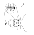
- FIG. 7 is a schematic illustration of a system 240 comprising two neurostimulator implants 242 (e.g., a first neurostimulator implant 242 a and a second neurostimulator implant 242 b ), each implant comprising circuitry 250 and one or more electrodes 24 , in accordance with some applications of the invention.
- two neurostimulator implants 242 e.g., a first neurostimulator implant 242 a and a second neurostimulator implant 242 b
- each implant comprising circuitry 250 and one or more electrodes 24 , in accordance with some applications of the invention.
- At least one of implants 242 (e.g., circuitry 250 thereof) comprises a breathing sensor 246 and at least one of implants 242 (e.g., circuitry 250 thereof) comprises a symmetry sensor 256 .
- Breathing sensor 246 typically comprises breathing sensor 86 and/or breathing sensor 206 , described hereinabove, and system 240 typically applies the excitatory current in response to the detected breathing-related parameter as described for systems 80 and/or 200 , mutatis mutandis.
- Implants 242 (e.g., circuitry 250 thereof) typically each comprise a driver 251 , configured to drive electrodes 24 .
- Symmetry sensor 256 typically comprises symmetry sensor 176 , described hereinabove, and system 240 typically calibrates the excitatory currents of the implants thereof (e.g., by configuring the circuitry of the implants) in response to the detected symmetry-related parameter as described for system 160 , mutatis mutandis.
- System 240 (e.g., the functionality thereof) is typically entirely provided by implants 242 , although a physician may optionally configure (e.g., manually configure) implants 242 via an antenna 252 of each implant.
- both implant 242 a and implant 242 b comprise a respective breathing sensor 246 and a respective symmetry sensor 256 .
- both implant 242 a and implant 242 b comprise a respective breathing sensor 246 , but only one of the implants comprises symmetry sensor 256 .
- both implant 242 a and implant 242 b comprise a respective symmetry sensor 256 , but only one of the implants comprises breathing sensor 246 .
- only one of implants 242 comprises breathing sensor 246
- only one of the implants comprises symmetry sensor 256 .
- FIG. 8 is a schematic illustration of a system 280 , comprising two neurostimulator implants 282 (e.g., a first neurostimulator implant 282 a and a second neurostimulator implant 282 b ), each implant comprising one or more electrodes 24 and circuitry 290 that comprises an antenna 292 , in accordance with some applications of the invention.
- Implants 282 are configured to receive a wireless signal via antenna 292 , and to responsively apply the excitatory current to the hypoglossal nerve of the subject, as described hereinabove for implants 42 and 122 , mutatis mutandis.
- implants 282 e.g., circuitry 290 thereof
- each comprise a driver 291 configured to drive electrodes 24 .
- System 280 further comprises a bedside extracorporeal control unit 300 comprising circuitry 306 that comprises an antenna 302 and a breathing sensor 286 , configured to detect a breathing-related parameter of the subject.
- Control unit 300 is configured to be placed in the vicinity of a bed 304 of the subject, such as under a mattress or on a nightstand of the subject.
- control unit 300 transmits, via an antenna 302 thereof, the wireless signal to which implants 282 respond.
- system 280 is thus similar to system 40 , with the functionalities of breathing detection and wireless signal transmission performed by bedside control unit 300 rather than by implantable control unit 44 .
- control unit 300 e.g., circuitry 306 thereof
- comprises a driver 307 configured to wirelessly drive electrodes 24 of both implants 282 .
- System 280 further comprises an additional extracorporeal control unit 294 , configured to configure system 280 so as to calibrate the excitatory current applied by implant 282 a and that applied by implant 282 b .
- control unit 294 is configured to configure implants 282 (e.g., circuitry 290 thereof) to calibrate the excitatory currents, e.g., as described with reference to control unit 94 configuring implants 82 of system 80 , mutatis mutandis.
- control unit 294 typically comprises a user interface 298 , and for some applications comprises and/or electronically interfaces with a symmetry sensor 296 .
- control unit 294 is configured to configure bedside control unit 300 (e.g., circuitry 306 thereof) to calibrate the excitatory currents, e.g., as described with reference to control unit 54 configuring implantable control unit 44 of system 40 , mutatis mutandis.
- bedside control unit 300 e.g., circuitry 306 thereof
- FIG. 9 is a schematic illustration of a system 320 , comprising two neurostimulator implants 322 (e.g., a first neurostimulator implant 322 a and a second neurostimulator implant 322 b ), and a bedside extracorporeal control unit 340 , in accordance with some applications of the invention.
- Bedside control unit 340 comprises circuitry 346 comprising an antenna 342 and a breathing sensor 326 .
- Bedside control unit 340 and components thereof are typically identical to bedside control unit 300 and components thereof, described hereinabove.
- Each implant 322 comprises one or more electrodes 24 and circuitry 330 that comprises an antenna 332 .
- At least one of implants 322 further comprises a symmetry sensor 336 .
- Implants 322 typically detect a symmetry-related factor of the subject, and responsively configure circuitry 330 to calibrate the excitatory currents of the implants, as described hereinabove for implants 162 , mutatis mutandis.
- system 320 is thus similar to system 160 , with the functionalities of breathing detection and wireless signal transmission performed by bedside control unit 340 rather than by implantable control unit 164 .
- implants 322 e.g., circuitry 330 thereof
- control unit 340 e.g., circuitry 346 thereof
- comprises a driver 347 configured to wirelessly drive electrodes 24 of both implants 162 .
- FIG. 10 is a schematic illustration of a system 360 , comprising two neurostimulator implants 362 (e.g., a first neurostimulator implant 362 a and a second neurostimulator implant 362 b ), and a bedside extracorporeal control unit 380 , in accordance with some applications of the invention.
- Implants 362 comprise circuitry 370 and are configured to receive a wireless signal via an antenna 372 , and to responsively apply the excitatory current to the hypoglossal nerve of the subject, as described hereinabove for implants 42 and 122 , mutatis mutandis.
- implants 362 e.g., circuitry 370 thereof
- Bedside control unit 380 comprises an antenna 382 and circuitry 386 comprising a breathing sensor 366 and a symmetry sensor 376 .
- Breathing sensor 366 typically comprises breathing sensor 286 described hereinabove.
- control unit 380 e.g., circuitry 386 thereof
- comprises a driver 387 configured to wirelessly drive electrodes 24 of both implants 362 .
- bedside control unit 380 is similar to bedside control unit 300 and/or bedside control unit 340 , with the addition of symmetry sensor 376 .
- system 380 is (1) similar to system 300 , with the functionality of symmetry detection and calibration of excitatory currents performed by bedside control unit 380 rather than by implantable control unit 294 , and/or (2) similar to system 340 , with the functionality of symmetry detection and calibration of excitatory currents performed by bedside control unit 380 rather than by implants 322 .
- FIG. 11 is a schematic illustration of a system 400 , comprising two neurostimulator implants 402 (e.g., a first neurostimulator implant 402 a and a second neurostimulator implant 402 b ), and a bedside extracorporeal control unit 420 , in accordance with some applications of the invention.
- Control unit 420 comprises circuitry 426 that comprises a symmetry sensor 416 and an antenna 412 .
- At least one of implants 402 (e.g., circuitry 410 thereof) comprises a breathing sensor 406 .
- implants 402 e.g., circuitry 410 thereof) each comprise a driver 411 , configured to drive electrodes 24 .
- control unit 420 (e.g., circuitry 426 thereof) comprises a driver 427 , configured to wirelessly drive electrodes 24 of both implants 402 .
- System 400 is thus (1) similar to system 360 , with the functionality of breathing detection performed by at least one of implants 402 rather than by bedside control unit 380 , and (2) similar to system 200 , with the functionalities of symmetry detection and calibration of excitatory currents performed by control unit 420 rather than by implantable control unit 204 .
- FIGS. 12-13 are schematic illustrations of systems, each system comprising two neurostimulator implants, an implantable control unit and a bedside control unit, in accordance with some applications of the invention. It will be appreciated from the descriptions hereinabove that it is possible to assign breathing sensing and symmetry sensing to various elements of apparatus, both implantable and extracorporeal, with a similar result of calibration of the excitatory currents that are applied in response to the breathing-related factor. Two further arrangements are now described with reference to FIGS. 12-13 .
- FIG. 12 shows a system 440 in which symmetry sensing is performed by a symmetry sensor 456 of circuitry 466 of a bedside control unit 460 that, in response to detection of the symmetry-related factor, wirelessly configures (e.g., via an antenna 462 ) an implantable control unit 444 (e.g., circuitry 464 thereof).
- Control unit 444 comprises a breathing sensor 446 , and transmits, via an antenna 448 , a wireless signal that is received by an antenna 452 of circuitry 450 of two neurostimulator implants 442 (e.g., a first neurostimulator implant 442 a and a second neurostimulator implant 442 b ) that responsively apply the excitatory current.
- two neurostimulator implants 442 e.g., a first neurostimulator implant 442 a and a second neurostimulator implant 442 b
- control unit 444 configures the excitatory currents of the two implants, e.g., as described for implantable control unit 44 , mutatis mutandis.
- control unit 460 calibrates the excitatory currents by directly configuring implants 442 (e.g., circuitry 450 thereof).
- implants 442 each comprise a driver 451 , configured to drive electrodes 24 .
- control unit 444 e.g., circuitry 464 thereof
- driver 465 configured to wirelessly drive electrodes 24 of both implants 442 .
- control unit 460 e.g., circuitry 466 thereof
- driver 467 configured to wirelessly drive electrodes 24 of both implants 442 .
- FIG. 13 shows a system 480 in which breathing sensing is performed by a breathing sensor 486 of circuitry 506 of a bedside control unit 500 .
- control unit 500 transmits, via an antenna 502 , a wireless signal that is received by a respective antenna 492 of circuitry 490 of two neurostimulator implants 482 (e.g., a first neurostimulator implant 482 a and a second neurostimulator implant 482 b ) that responsively apply the excitatory current.
- two neurostimulator implants 482 e.g., a first neurostimulator implant 482 a and a second neurostimulator implant 482 b
- An implantable control unit 484 comprises circuitry 504 comprising a symmetry sensor 496 that detects the symmetry-related factor, and responsively configures (e.g., via an antenna 502 ) neurostimulator implants 482 (e.g., circuitry 490 thereof) so as to calibrate the excitatory currents of the two implants (e.g., as described for implantable control unit 204 , mutatis mutandis).
- control unit 484 receives the wireless signal from control unit 500 and responsively transmits a second wireless signal that drives implants 482 .
- implantable control unit 484 calibrates the excitatory currents by configuring the second wireless signal (e.g., by configuring circuitry 504 of the implantable control unit).
- implants 482 each comprise a driver 491 , configured to drive electrodes 24 .
- control unit 484 e.g., circuitry 504 thereof
- control unit 500 e.g., circuitry 506 thereof
- driver 507 configured to wirelessly drive electrodes 24 of both implants 482 .
- the implants described herein are configured to become fixed with respect to the anatomy of the subject after implantation.
- the implants may comprise hooks or barbs that penetrate into tissue, and/or may be surface treated or coated with a material that promotes tissue growth and/or fibrosis (e.g., expanded polytetrafluoroethylene).
Landscapes
- Health & Medical Sciences (AREA)
- Life Sciences & Earth Sciences (AREA)
- Engineering & Computer Science (AREA)
- Biomedical Technology (AREA)
- Animal Behavior & Ethology (AREA)
- General Health & Medical Sciences (AREA)
- Public Health (AREA)
- Veterinary Medicine (AREA)
- Nuclear Medicine, Radiotherapy & Molecular Imaging (AREA)
- Radiology & Medical Imaging (AREA)
- Biophysics (AREA)
- Heart & Thoracic Surgery (AREA)
- Molecular Biology (AREA)
- Physics & Mathematics (AREA)
- Pathology (AREA)
- Medical Informatics (AREA)
- Surgery (AREA)
- Neurology (AREA)
- Neurosurgery (AREA)
- Physiology (AREA)
- Pulmonology (AREA)
- Cardiology (AREA)
- Prostheses (AREA)
- Electrotherapy Devices (AREA)
Abstract
Apparatus comprising (1) a breathing sensor, configured to detect a breathing-related factor of a subject; (2) at least a first electrode configured to be placed in a vicinity of a respective first hypoglossal nerve, and to be driven, in response to the detected breathing-related factor, to apply a first electrical current to the first hypoglossal nerve; (3) at least a second electrode configured to be placed in a vicinity of a respective second hypoglossal nerve, and to be driven, in response to the detected breathing-related factor, to apply a second electrical current to the second hypoglossal nerve; and (4) circuitry configured to, in response to a detected symmetry-related factor indicative of a degree of symmetry of the subject, configure at least one current selected from the group consisting of: the first current and the second current. Other embodiments are also described.
Description
This application is a Continuation of U.S. patent application Ser. No. 14/445,443 to Gross, filed Jul. 29, 2014, and entitled “Bilateral Feedback,” which published as US 2015/0039046 (now U.S. Pat. No. 9,457,186), and which claims priority from U.S. Provisional Patent Application 61/860,323 to Gross, filed Jul. 31, 2013, entitled “Bilateral Feedback”, which is incorporated herein by reference. This application is related to U.S. Ser. No.13/885,360 to Gross (now abandoned), which published as US 2013/0261693, and is a US national phase of PCT IL2011/000870, filed Nov. 10, 2011 and published as WO 2012/066532 to Gross, which claims the priority of, and is a continuation-in-part of, U.S. patent application Ser. No. 12/946,246, filed Nov. 15, 2010 and published as US 2012/0123498 to Gross, now abandoned, all of which are incorporated herein by reference.
Some applications of the present invention generally relate to medical apparatus. More specifically, some applications of the present invention relate to neurostimulator implants, and to apparatus and techniques for use therewith.
Sleep apnea is a chronic sleep breathing disorder typically characterized by abnormal pauses (apneas) in an individual's breathing, ranging from seconds to minutes in duration, or by instances of abnormally low breathing. Sleep apnea is associated with cardiovascular disease, myocardial infarction, high blood pressure, stroke, arrhythmias, diabetes, sleep-deprived driving accidents, and cerebrovascular disease.
Current treatments include positive airway pressure (PAP) therapy (e.g., continuous positive expiratory pressure; CPAP), oral appliances, surgery (e.g., genioglossus advancement, tongue radiofrequency treatment, midline glossectomy, hyoid suspension and maxillomandibular advancement), lifestyle changes (e.g., positional therapy and weight loss), and implantable muscle stimulators.
For some applications of the invention, two implants are implanted in a vicinity of respective hypoglossal nerves of a subject, each implant comprising at least one electrode. A breathing sensor is configured to detect a breathing-related factor of a subject. A driver is configured to drive each electrode to apply a respective electrical current to a respective hypoglossal nerve. Circuitry is configured to calibrate the currents applied by the electrodes in response to a detected symmetry-related factor that is indicative of a degree of symmetry of the subject. For some such applications, a symmetry sensor detects the symmetry-related factor.
For some applications the symmetry sensor is extracorporeal. For some applications the symmetry sensor is implantable. For some applications the breathing sensor is intracorporeal. For some applications the breathing sensor is implantable.
There is therefore provided, in accordance with an application of the present invention, apparatus for use with a body of a subject, the apparatus including:
a breathing sensor, configured to detect a breathing-related factor of the subject;
at least a first electrode configured to be placed in a vicinity of a respective first hypoglossal nerve of the subject, and to be driven, in response to the detected breathing-related factor, to apply a first electrical current to the first hypoglossal nerve;
at least a second electrode configured to be placed in a vicinity of a respective second hypoglossal nerve of the subject, and to be driven, in response to the detected breathing-related factor, to apply a second electrical current to the second hypoglossal nerve; and
circuitry configured to, in response to a detected symmetry-related factor indicative of a degree of symmetry of the subject, configure at least one current selected from the group consisting of: the first current and the second current.
In an application, the breathing sensor includes exactly one breathing sensor.
In an application, the first electrode and the second electrode are configured to be placed by being injected into the subject.
In an application, the circuitry is further configured to configure at least the first electrical current to initiate action potentials in the first hypoglossal nerve without directly initiating contraction of muscle of the subject.
In an application, the circuitry is further configured to configure at least the first electrical current to have a frequency of between 10 and 40 Hz.
In an application, the circuitry is further configured to configure at least the first electrical current to have an amplitude of between 0.1 and 3 mA.
In an application, the apparatus further includes at least one driver, configured to drive at least one electrode selected from the group consisting of: the at least first electrode and the at least second electrode.
In an application, the at least one driver includes exactly one driver, configured to wirelessly drive the at least first electrode and the at least second electrode.
In an application, the at least one driver includes (1) a first driver, coupled to the at least first electrode, and configured to drive the at least first electrode, and (2) a second driver, coupled to the at least second electrode, and configured to drive the at least second electrode.
In an application, the apparatus further includes a symmetry sensor, configured to detect the symmetry-related factor.
In an application, the symmetry sensor is configured to detect a mechanical symmetry of the subject.
In an application, the symmetry sensor includes an accelerometer.
In an application, the symmetry sensor is configured to detect an electrical symmetry of the subject.
In an application, the symmetry sensor includes an electrode.
In an application, the electrode includes an electromyographic electrode.
In an application, the apparatus further includes an extracorporeal control unit that includes the symmetry sensor, and is configured to transmit a wireless signal at least in part responsively to the detected symmetry-related factor.
In an application, the extracorporeal control unit further includes the breathing sensor.
In an application, the circuitry is configured to receive the wireless signal, and to configure the at least one selected current in response to receiving the wireless signal.
In an application, the extracorporeal control unit is configured to provide power wirelessly to the circuitry.
In an application, the circuitry includes a first circuitry configured to configure the first current in response to the detected symmetry-related factor, and the apparatus further includes:
a first implant, configured to be implanted in the vicinity of the first hypoglossal nerve, and including the first electrode and the first circuitry; and
a second implant, configured to be implanted in the vicinity of the second hypoglossal nerve, and including the second electrode and second circuitry configured to configure the second current in response to the detected symmetry-related factor.
In an application, the apparatus further includes a control unit, including a symmetry sensor, configured to detect the symmetry-related factor, to transmit a wireless signal at least in part responsively to the detected symmetry-related factor, and to configure the wireless signal to independently address the first implant and the second implant.
In an application, at least one implant selected from the group consisting of: the first implant and the second implant, includes the breathing sensor.
In an application, at least one implant selected from the group consisting of: the first implant and the second implant, includes a symmetry sensor, configured to detect the symmetry-related factor.
In an application, the apparatus further includes a control unit, including the circuitry, and configured to configure at least the at least one selected current in response to the detected symmetry-related factor.
In an application, the control unit includes an implantable control unit implantable in the body of the subject.
In an application, the control unit includes the breathing sensor.
In an application, the control unit includes exactly one control unit, and is configured to configure the first current and the second current in response to the detected symmetry-related factor.
In an application, the control unit includes an extracorporeal control unit.
In an application, the control unit includes a symmetry sensor, configured to detect the symmetry-related factor.
In an application, the control unit is configured to configure at least the at least one selected current by transmitting a wireless signal in response to detecting the symmetry-related factor.
There is further provided, in accordance with an application of the present invention, a method for use with a body of a subject, the method including:
detecting a breathing-related factor of the subject;
in response to the detected breathing-related factor:
-
- applying a first electrical current to a first hypoglossal nerve of the subject, and
- applying a second electrical current to a second hypoglossal nerve of the subject; and
in response to a detected symmetry-related factor indicative of a degree of symmetry of the subject, configuring at least one current selected from the group consisting of: the first current and the second current.
In an application, the method further includes configuring at least the first electrical current to initiate action potentials in the first hypoglossal nerve without directly initiating contraction of muscle of the subject.
In an application, detecting the breathing-related factor includes extracorporeally detecting the breathing-related factor.
In an application, the method further includes detecting the symmetry-related factor.
In an application, detecting the symmetry-related factor includes detecting a mechanical symmetry of the subject.
In an application, detecting the symmetry-related factor includes detecting an electrical symmetry of the subject.
In an application, detecting the symmetry-related factor includes detecting an electromyographic factor of the subject.
In an application, detecting the symmetry-related factor includes extracorporeally detecting the symmetry-related factor.
In an application, the method further includes transmitting a wireless signal at least in part responsively to the detected symmetry-related factor.
In an application, the method further includes intracorporeally receiving the wireless signal, and configuring the at least one selected current in response to receiving the wireless signal.
In an application, the method further includes extracorporeally transmitting wireless power, and intracorporeally receiving the wireless power.
In an application, configuring the at least one selected current includes configuring the first current and the second current.
In an application, the method further includes transmitting a wireless signal at least in part responsively to the detected symmetry-related factor, and configuring the wireless signal to (1) induce the configuring of the first current, and (2) induce the configuring of the second current independently of the inducing of the configuring of the first current.
In an application:
detecting the breathing-related parameter includes detecting the breathing-related parameter using a breathing sensor;
applying the first electrical current includes applying the first electrical current using a first electrode disposed in a vicinity of the first hypoglossal nerve;
applying the second electrical current includes applying the second electrical current using a second electrode disposed in a vicinity of the second hypoglossal nerve; and
configuring the at least one selected current includes configuring the at least one selected current using circuitry configured to configure the at least one selected current in response to the detected symmetry-related factor.
In an application, applying the first electrical current includes applying the first electrical current using a first electrode that has been injected into the subject.
In an application, the method further includes detecting the symmetry-related factor using a symmetry sensor.
In an application, detecting the symmetry-related factor includes detecting a mechanical symmetry of the subject.
In an application, detecting the symmetry-related factor includes detecting the symmetry-related factor using a symmetry sensor that includes an accelerometer.
In an application, detecting the symmetry-related factor includes detecting an electrical symmetry of the subject.
In an application, detecting the symmetry-related factor includes detecting the symmetry-related factor using a symmetry sensor that includes an electrode.
In an application, detecting the symmetry-related factor includes detecting the symmetry-related factor using a symmetry sensor that includes an electromyographic electrode.
In an application:
detecting the symmetry-related factor includes detecting the symmetry-related factor using an extracorporeal control unit that includes the symmetry sensor, and
the method further includes transmitting a wireless signal at least in part responsively to the detected symmetry-related factor.
In an application, detecting the breathing-related factor includes detecting the breathing-related factor using the extracorporeal control unit, the extracorporeal control unit including the breathing sensor.
In an application, the method further includes receiving the wireless signal using the circuitry.
In an application, the method further includes providing power wirelessly to the circuitry using the extracorporeal control unit.
In an application:
the circuitry includes a first circuitry,
a first implant includes the first circuitry and the first electrode,
applying the first current includes applying the first current using the first electrode of the first implant,
a second implant includes the second electrode and second circuitry, and
applying the second current includes applying the second current using the second electrode of the second implant, and
In an application, configuring the at least one selected current includes:
configuring the first current using the first circuitry of the first implant, and
configuring the second current using the second circuitry of the second implant.
In an application, the method further includes:
detecting the symmetry-related factor using a symmetry sensor of a control unit, and
using the control unit,
-
- transmitting a wireless signal at least in part responsively to the detected symmetry-related factor, and
- configuring the wireless signal to independently address the first implant and the second implant.
In an application, at least one implant selected from the group consisting of: the first implant and the second implant, includes the breathing sensor, and detecting the breathing-related factor includes detecting the breathing-related factor using the breathing sensor of the at least one selected implant.
In an application, at least one implant selected from the group consisting of: the first implant and the second implant, includes a symmetry sensor, and the method further includes detecting the symmetry-related factor using the symmetry sensor of the at least one selected implant.
In an application, the circuitry includes circuitry of a control unit, and configuring the at least one selected current includes configuring the at least one selected current using the circuitry of the control unit.
In an application, configuring the at least one selected current includes configuring the at least one selected current using circuitry of an implantable control unit, disposed within the body of the subject.
In an application, the control unit includes the breathing sensor, and detecting the breathing-related factor includes detecting the breathing-related factor using the breathing sensor of the control unit.
In an application, configuring the at least one selected current includes configuring the at least one selected current using circuitry of an extracorporeal control unit.
In an application, the control unit includes a symmetry sensor, and the method further includes detecting the symmetry-related factor using the symmetry sensor of the control unit.
In an application, the method further includes transmitting a wireless signal using the control unit, in response to detecting the symmetry-related factor.
In an application, the method further includes, using the circuitry, configuring at least the first electrical current to initiate action potentials in the first hypoglossal nerve without directly initiating contraction of muscle of the subject.
There is further provided, in accordance with an application of the present invention, a method, including:
implanting, in a vicinity of a first anatomical site of a subject, a first implant including at least one electrode and circuitry configured to drive the at least one electrode of the first implant to apply a first electrical current to the first anatomical site;
implanting, in a vicinity of a second anatomical site of a subject, a second implant including at least one electrode and circuitry configured to drive the at least one electrode of the second implant to apply a second electrical current to the second anatomical site; and
subsequently, detecting a symmetry-related factor of the subject indicative of a symmetry of the subject, and in response to the detected symmetry-related factor, configuring at least one implant selected from the group consisting of: the first implant and the second implant.
In an application, implanting includes injecting.
In an application, implanting the first implant includes implanting the first implant in a vicinity of a first hypoglossal nerve of the subject, and implanting the second implant includes implanting the second implant in a vicinity of a second hypoglossal nerve of the subject.
In an application, detecting includes detecting a mechanical symmetry of the subject.
In an application, detecting includes detecting an electrical symmetry of the subject.
In an application, configuring includes modifying the current applied by the at least one selected implant.
In an application, modifying includes altering a balance of amplitude between the first electrical current and the second electrical current.
The present invention will be more fully understood from the following detailed description of applications thereof, taken together with the drawings, in which:
Reference is made to FIG. 1 , which is a schematic illustration of a neurostimulator implant 22 and an implantation site therefor, in accordance with some applications of the invention. Implant 22 is implanted, e.g., by being injected, at an implantation site 10 in a vicinity of a nerve of the subject, such as a hypoglossal nerve 12 of the subject. Implant 22 comprises one or more (e.g., two) electrodes 24, and typically at least one antenna, as described hereinbelow in accordance with respective applications of the invention.
Typically, implant 22 is implanted within 8 mm (e.g., within 5 mm, e.g., within 3 mm, e.g., within 1 mm) of hypoglossal nerve 12. Further typically, implant 22 is implanted such that an electrode 24 that serves as a cathode is disposed within 5 mm (e.g., within 3 mm, e.g., within 1 mm) of the hypoglossal nerve, and/or such that an electrode 24 that serves as an anode is disposed within 8 mm (e.g., within 5 mm, e.g., within 3 mm, e.g., within 1 mm) of the hypoglossal nerve. Implant 22 may be implanted such that at least a portion of the implant (e.g., at least one electrode thereof) is in contact with the hypoglossal nerve.
For illustrative purposes, the following anatomical features are also labeled in FIG. 1 : Hypoglossal canal 14, extrinsic muscles 16 of the tongue, intrinsic muscles 18 of the tongue, and medulla oblongata 8.
It is typically desirable that induced contraction of the tongue muscle tissue be generally symmetric (e.g., with respect to the central sagittal plane of the subject). Therefore, two implants 22 are typically implanted contralaterally; each implant in a vicinity of a respective hypoglossal nerve. For some applications, the symmetry of the contraction of the tongue muscle tissue is achieved and/or increased by calibrating the excitatory currents of the implants so as to provide that the excitatory current reaching each hypoglossal nerve is generally the same as the excitatory current reaching the other hypoglossal nerve (that is, generally symmetric application of excitatory current). For some applications, symmetric contraction of the tongue muscle tissue is achieved and/or increased by calibrating the excitatory currents of the implants so as to apply a different current to each hypoglossal nerve (that is, asymmetric application of excitatory current), such as in cases in which one hypoglossal nerve is less responsive to the excitatory current than is the other hypoglossal nerve.
For some applications (e.g., when the neurostimulator implant comprises an injectable implant), it may be difficult to implant the implant at a precise position and/or distance from the hypoglossal nerve, and the distance between one implant and its respective hypoglossal nerve may be different from that between the other implant and its respective hypoglossal nerve. Therefore, for some applications, it is desirable to calibrate the currents of the implants such that each implant applies a different excitatory current, e.g., to counter the difference in distance, and thereby resistance, between each implant and its respective hypoglossal nerve. Such calibration may be useful both for applications in which generally symmetric application of excitatory current is desired, and for applications in which asymmetric application of excitatory current is desired.
Therefore, calibration of the excitatory currents may comprise, with respect to one or more characteristics (e.g., amplitude and/or frequency) (1) maintaining equality between the current applied by one implant and the current applied by the other implant, or (2) creating and/or maintaining an imbalance between the current applied by one implant and the current applied by the other implant.
Typically, it is desirable to induce contraction of the muscle tissue by exciting (i.e., inducing action potentials in) the nerve, rather than by direct electrical stimulation of the muscle tissue by the implant. This is typically achieved by applying a current having a lower amplitude and a higher frequency than that used for directly stimulating muscle tissue. For example, the excitatory current may have a frequency of greater than 10 Hz, less than 40 Hz, and/or between 10 and 40 Hz, and/or may have an amplitude of greater than 0.1 mA, less than 3 mA, and/or between 0.1 and 3 mA. For such applications, the calibration of excitatory currents described hereinabove may be particularly useful e.g., such that a minimum amplitude required for a given implanted implant to excite the nerve may be established, and used by that implant, rather than that implant using a higher amplitude than that required.
It is to be noted that the hypoglossal nerve is used herein as an example, and that applications of the invention may be used to facilitate symmetric contraction of other muscles and/or excitation of other nerve pairs.
Reference is made to FIGS. 2-13 , which are schematic illustrations of respective systems, each of the systems comprising two neurostimulator implants, and being configured to induce generally symmetric contraction of the tongue of the subject by calibrating respective excitatory currents applied by the neurostimulator implants, in accordance with some applications of the invention. Each of the systems described with reference to FIGS. 2-13 comprises a breathing sensor, configured to detect a breathing-related parameter of the subject, and circuitry configured to configure the current applied by at least one of the neurostimulator implants in response to a detected symmetry-related factor indicative of a symmetry of the subject. Typically, the neurostimulator implants described with reference to FIGS. 2-13 comprise, or are identical or analogous to, implants 22 described with reference to FIG. 1 . Some of the systems further comprise a symmetry sensor, configured to detect the symmetry-related factor. Each system is configured such that the implants apply excitatory current in response to the breathing-related parameter, e.g., when the breathing detector detects a sleep apnea event.
Reference is made to FIG. 2 , which is a schematic illustration of a system 40, comprising two neurostimulator implants 42 (e.g., a first neurostimulator implant 42 a and a second neurostimulator implant 42 b), and an implantable (e.g., subcutaneously implantable) control unit 44 that comprises circuitry 64 comprising a breathing sensor 46, in accordance with some applications of the invention. Implantable control unit 44 (e.g., circuitry 64 thereof) typically comprises an antenna 48 and is configured to drive the antenna to transmit at least one wireless signal when breathing sensor 46 detects a sleep apnea event.
For some applications, breathing sensor 46 detects acceleration, momentum and/or velocity of the sensor and/or a portion of the body of the subject, caused by the breathing of the subject. Alternatively or additionally, sensor 46 may detect one or more other breathing-related factors. Sensor 46 may comprise a piezoelectric sensor, a piezoresistive sensor, a capacitive sensor, an inductive sensor, a magnetic sensor, and/or a sensor that detects variations in impedance of a conductive fluid.
For some applications, apparatus and methods described in U.S. Pat. No. 5,304,208 to Inguaggiato et al. and U.S. Pat. No. 5,454,838 to Vallana et al., which are incorporated herein by reference, are utilized in combination with the apparatus and methods described herein, in order to detect the breathing-related factor of the subject. Alternatively or additionally, sensor 46 comprises the hemodynamic sensor embedded in the tip of the SonRtip™ atrial sensing/pacing lead, which is instead positioned in the subject to directly measure pressure changes associated with respiration, rather than to measure hemodynamic parameters.
Each implant 42 comprises one or more (e.g., two) electrodes 24, and circuitry 50 comprising an antenna 52. Circuitry 50 is configured to receive (e.g., via antenna 52) the wireless signal from control unit 44, and at least in part responsively to the wireless signal, to drive the electrodes to apply the excitatory current to the hypoglossal nerve. For example, implant 42 (e.g., circuitry 50 thereof) may comprise a driver 51, configured to drive electrodes 24. Each implant 42 is independently addressable by control unit 44, e.g., by the wireless signal from the control unit being encoded. This allows control unit 44 to drive each implant to apply current that is different in one or more characteristics from current driven by the other implant, and thereby to calibrate the excitatory currents of the implants, e.g., as described hereinbelow. Typically, control unit 44 drives both implants 42 at generally the same time (e.g., simultaneously, or within 1 second of each other).
Typically, implants 42 are powered by control unit 44 via the wireless signal. That is, typically the wireless signal includes wireless power, and control unit 44 thus wirelessly drives circuitry 50 of implants 42 to drive electrodes 24 to apply the excitatory current. For example, antenna 52 may comprise an induction antenna (e.g., an induction loop) or a rectifying antenna, and control unit 44 (e.g., circuitry 64 thereof) may comprise a driver 65, configured to drive electrodes 24 via the wireless power.
Subsequent to implantation of implants 42 and control unit 44 (e.g., immediately subsequently, or during a subsequent appointment), a physician detects a degree of symmetry of contraction of the tongue and/or other tissues, induced by implants 42. For some applications, the physician (1) induces control unit 44 to drive the implants as though breathing sensor 46 had detected a sleep apnea event, and (2) observes the subject visually and/or using a symmetry sensor configured to detect a symmetry-related factor (e.g., degree of symmetry) of the subject. For example, the physician may wirelessly induce control unit 44 to drive the implants, by pressing a “stimulate” button of user interface 58. In response to detecting the symmetry, control unit 44 (e.g., circuitry 64 thereof) is configured to calibrate the excitatory currents of implants 42, typically to increase the degree of symmetry. For example, if the tongue of the subject moves toward one side during contraction, control unit 54 may be used to configure control unit 44 to increase the amplitude of the current of one of implants 42 and/or reduce the amplitude of the current applied by the other implant. For example, for applications in which the characteristic of the current to be modified is amplitude, if the tongue of the subject is disposed to the right, the amplitude of the current applied by the implant on the left side of the subject may be (further) increased relative to that applied by the implant on the right side of the subject (e.g., by configuring the left-side implant to increase its current's amplitude, and/or by configuring the right-side implant to decrease its current's amplitude). As described hereinabove, other characteristics of the excitatory current that may be modified in this way include duty cycle, and for some applications, frequency. Typically, the process of calibrating the excitatory currents to increase symmetry is an iterative process.
For some applications, extracorporeal control unit 54 comprises symmetry sensor 56 (hence the symmetry sensor is shown in phantom in FIG. 2 ). For some applications, symmetry sensor 56 is distinct from, but can electronically interface with, control unit 54. For some applications in which control unit 54 comprises or interfaces with symmetry sensor 56, system 40 at least in part automatically performs the process of (1) inducing control unit 44 to drive the implants, (2) detecting a symmetry-related factor (e.g., a degree of symmetry), and (3) configuring control unit 44 to increase the degree of symmetry. Control unit 54 is shown in FIG. 2 as a wand-type control unit (e.g., similar in appearance to that in the pacemaker art) purely as an illustrative example, and not by way of limitation.
For some applications, symmetry sensor 56 is distinct from control unit 54 and the operating physician fully-manually or partially-manually controls control unit 54 (e.g., via a user interface 58), at least in part responsively to information received from the symmetry sensor. Interface 58 may also be used for applications in which the physician visually observes the degree of symmetry (e.g., when no symmetry sensor is used).
For some applications, symmetry sensor 56 comprises a camera, configured to detect mechanical symmetry, e.g., in combination with visual markers (e.g., fiducial markers) coupled to the subject. For some applications, symmetry sensor 56 comprises one or more induction coils, and is used to detect mechanical symmetry, e.g., in combination with magnetic markers (which may comprise, or be comprised by, implants 42), coupled to the subject. For some applications, symmetry sensor 56 comprises at least one electrode, and is configured to detect an electrical symmetry of the subject. For example, symmetry sensor 56 may be configured to detect action potentials in the hypoglossal nerve (e.g., sensor 56 may comprise an action potential sensor), or may comprise an electromyographic electrode, and be configured to detect electromyographic signals (e.g., sensor 56 may comprise an EMG sensor).
For some applications, extracorporeal control unit 54 is alternatively or additionally configured to configure implants 42 (e.g., circuitry 50 thereof) so as to calibrate excitatory currents thereof. For example, control unit 54 may be configured to configure implants 42 directly, rather than configuring implantable control unit 44. For such applications, control unit 44 may drive implants 42 (via the wireless signal) to apply the excitatory currents, but itself not calibrate the implants.
Reference is made to FIG. 3 , which is a schematic illustration of a system 80, comprising two neurostimulator implants 82 (e.g., a first neurostimulator implant 82 a and a second neurostimulator implant 82 b), in accordance with some applications of the invention. Implants 82 are typically identical to implants 42 described hereinabove, mutatis mutandis, except for where noted. At least one of implants 82 (e.g., implant 82 a, as shown) comprises a breathing sensor 86. For some applications, breathing sensor 86 may comprise breathing sensor 46 (described with reference to FIG. 2 ), one or more components, and/or a functionality thereof.
Implants 82 comprise electrodes 24 and circuitry 90 comprising a driver 91 configured to drive the electrodes to apply the excitatory current to the hypoglossal nerve in response to breathing sensor 86 detecting a sleep apnea event. For some applications, each of implants 82 comprises a respective breathing sensor 86, and is configured to apply the excitatory current in response to detection of the sleep apnea event by its respective breathing sensor. For some applications, at least one of implants 82 is configured to apply the excitatory current at least in part responsively to detection of the sleep apnea event by the breathing sensor of the other implant. For example, only one of implants 82 may comprise a breathing sensor 86, and both implants apply the excitatory current in response to the detection of the sleep apnea event by the one breathing sensor. For example, the implant that comprises the breathing sensor may be configured to transmit at least one wireless signal via an antenna 92 when the breathing sensor detects a sleep apnea event, and the other implant may be configured to apply the excitatory current at least in part responsively to the wireless signal.
Alternatively or additionally, both of implants 82 comprise a respective breathing sensor 86, and are configured to apply the excitatory current in response to the detection of the sleep apnea event by one or more of the breathing sensors (e.g., the implants are configured to wirelessly communicate (e.g., negotiate) via respective antennas 92 in order to collectively detect the sleep apnea event and/or to collectively determine if/when to apply the excitatory current).
It is to be noted that, in contrast to system 40 described hereinabove with reference to FIG. 2 , system 80 typically does not comprise an implantable control unit that is distinct from the neurostimulator implants. That is, compared to system 40, breathing sensor functionality is moved from the distinct implantable control unit 44 to one or both of implants 82.
Subsequent to implantation of implants 82 (e.g., immediately subsequently, or during a subsequent appointment), a physician detects a degree of symmetry of contraction of the tongue and/or other tissues induced by implants 82. For some applications, the physician (1) induces implants 92 to apply the excitatory current as though breathing sensor(s) 86 had detected a sleep apnea event, and (2) observes the subject visually and/or using a symmetry sensor 96. In response to detecting the symmetry, at least one of implants 82 is configured (e.g., adjusted), typically to increase the degree of symmetry, thereby calibrating the excitatory currents of system 80. For example, if the tongue of the subject moves toward one side during contraction, control unit 94 may be used to increase the amplitude of the current of one of implants 82 and/or reduce the amplitude of the current applied by the other implant (e.g., as described hereinabove, mutatis mutandis). Typically, the process of calibrating the excitatory currents to increase symmetry is an iterative process.
For some applications, extracorporeal control unit 94 comprises symmetry sensor 96 (hence the symmetry sensor is shown in phantom in FIG. 3 ). For some applications, symmetry sensor 96 is distinct from, but can electronically interface with, control unit 94. For some applications in which control unit 94 comprises or interfaces with symmetry sensor 96, system 80 at least in part automatically performs the process of (1) inducing implants 82 to apply the excitatory current, (2) detecting a symmetry-related factor (e.g., a degree of symmetry), and (3) configuring implants 82 to increase the degree of symmetry. Control unit 94 is shown in FIG. 2 as a wand-type control unit (e.g., similar in appearance to that in the pacemaker art) purely as an illustrative example, and not by way of limitation.
For some applications, symmetry sensor 96 is distinct from control unit 94 and the operating physician fully-manually or partially-manually controls control unit 94 (e.g., via a user interface 98), at least in part responsively to information received from the symmetry sensor. Interface 98 may also be used for applications in which the physician visually observes the degree of symmetry (e.g., when no symmetry sensor is used). For some applications, symmetry sensor 96 comprises symmetry sensor 56, described hereinabove with reference to FIG. 2 .
As described hereinabove, in contrast to system 40 described hereinabove with reference to FIG. 2 , system 80 typically does not comprise an implantable control unit that is distinct from the neurostimulator implants. Thus, compared to system 40, instead of implantable control unit 44 being calibratable, at least one of implants 82 is calibratable.
Reference is made to FIG. 4 , which is a schematic illustration of a system 120, comprising two neurostimulator implants 122 (e.g., a first neurostimulator implant 122 a and a second neurostimulator implant 122 b), and an implantable (e.g., subcutaneously implantable) control unit 124 that comprises circuitry 144 comprising a breathing sensor 126 and a symmetry sensor 136, in accordance with some applications of the invention. Implantable control unit 124 (e.g., circuitry 144 thereof) typically comprises an antenna 128 and is configured to drive the antenna to transmit at least one wireless signal when breathing sensor 126 detects a sleep apnea event. Implants 122 are typically identical to implants 42 described hereinabove, mutatis mutandis.
Each implant 122 comprises one or more (e.g., two) electrodes 24, and circuitry 130 comprising an antenna 132. Circuitry 130 is configured to receive (e.g., via antenna 132) the wireless signal from control unit 124, and at least in part responsively to the wireless signal, to drive the electrodes 24 to apply the excitatory current to the hypoglossal nerve. For example, implant 122 (e.g., circuitry 130 thereof) may comprise a driver 131, configured to drive electrodes 24. Each implant 122 is independently addressable by control unit 124, e.g., by the wireless signal from the control unit being encoded. This allows control unit 124 to drive each implant to apply current that is different in one or more characteristics from current driven by the other implant, and thereby to control a balance between the currents of the implants, as described hereinbelow. Typically, control unit 124 drives both implants 122 at generally the same time (e.g., as described hereinabove, mutatis mutandis).
Typically, implants 122 are powered by control unit 124 via the wireless signal. That is, typically the wireless signal includes wireless power, and control unit 124 thus wirelessly drives circuitry 130 of implants 122 to drive electrodes 24 to apply the excitatory current. For example, antenna 132 may comprise an induction antenna (e.g., an induction loop) or a rectifying antenna, and control unit 124 (e.g., circuitry 144 thereof) may comprise a driver 145, configured to drive electrodes 24 via the wireless power.
Subsequent to implantation of implants 122 and control unit 124 (e.g., immediately subsequently, or following a subsequent activation of the implants and/or the control unit), system 120 automatically calibrates itself. Control unit 124 drives implants 122 to apply the excitatory current, and symmetry sensor 136 detects a symmetry-related factor of the subject in response to the current, e.g., a degree of mechanical and/or electrical symmetry of contraction of the tongue. In response to the detected symmetry-related factor, control unit 124 (e.g., circuitry 144 thereof) configures (e.g., reconfigures) the wireless signal via which it drives implants 122 so as to calibrate the excitatory currents applied by the implants (e.g., by adjusting the excitatory current applied by at least one of the implants). For example, if the tongue of the subject moves toward one side during contraction, control unit 124 may increase the amplitude of the current of one of implants 122 and/or reduce the amplitude of the current applied by the other implant (e.g., as described hereinabove, mutatis mutandis). Typically, the process of calibrating the excitatory currents to increase symmetry is an iterative process, and further typically continues beyond an initial configuration period, e.g., continues for the life of system 120.
Because control unit 124 typically drives implants 122 to apply the excitatory current only when breathing sensor 126 detects a sleep apnea event, for some applications it is desirable to conduct an initial calibration step prior to reliance on system 120 to treat a true sleep apnea event: Subsequent to implantation of implants 122 and control unit 124, a physician initiates the initial calibration step by inducing (e.g., wirelessly) control unit 124 to drive the implants as though breathing sensor 126 had detected a sleep apnea event, such that the control unit (e.g., circuitry 144 thereof) may configure the wireless signal and thereby calibrate the excitatory currents. For some applications, the physician may conduct one or more additional (e.g., manual) configurations using an extracorporeal control unit, such as those described hereinabove, mutatis mutandis.
As described hereinabove, in contrast to systems 40 and 80 described hereinabove with reference to FIG. 2 , system 120 typically does not comprise an extracorporeal control unit comprising or interfacing with a symmetry sensor. Thus, compared to systems 40 and 80, symmetry-detecting functionality and signal-configuring functionality is moved from the extracorporeal control unit to implantable control unit 124.
Reference is made to FIGS. 5 and 6 , which are schematic illustrations of respective systems, each system comprising two neurostimulator implants and an implantable control unit, in accordance with some applications of the invention. FIG. 5 shows a system 160 comprising two neurostimulator implants 162 (e.g., a first neurostimulator implant 162 a and a second neurostimulator implant 162 b) and an implantable control unit 164, and FIG. 6 shows a system 200 comprising two neurostimulator implants 202 (e.g., a first neurostimulator implant 202 a and a second neurostimulator implant 202 b) and an implantable control unit 204. Systems 160 and 200 each comprise an implantable breathing sensor and an implantable symmetry sensor, and both have automatic-calibration functionality such as described hereinabove for system 120, mutatis mutandis. Typically, the automatic-calibration functionality of systems 160 and 200 is identical to that of system 120 except for differences described hereinbelow.
System 160 (FIG. 5 ) comprises a breathing sensor 166 that is a component of implantable control unit 164 (e.g., of circuitry 184 thereof), and a symmetry sensor 176 that is a component of at least one of implants 162 (e.g., of circuitry 170 thereof). That is, (1) control unit 164 comprises breathing sensor 166, in addition to an antenna 168, and (2) at least one of implants 162 comprises symmetry sensor 176, in addition to an antenna 172. Implantable control unit 164 detects (using breathing sensor 166) the breathing-related parameter, and responsively transmits a wireless signal (using antenna 168), as described hereinabove for implantable control unit 44, breathing sensor 46 and antenna 168 of system 40, mutatis mutandis, and/or as described for implantable control unit 124, breathing sensor 126, and antenna 128 of system 120, mutatis mutandis.
For some applications, implants 162 (e.g., circuitry 170 thereof) each comprise a driver 171, configured to drive electrodes 24. For some applications, implantable control unit 164 (e.g., circuitry 184 thereof) comprises a driver 185, configured to wirelessly drive electrodes 24 of both implants 162. System 160 automatically calibrates the excitatory currents of the implants 162 in response to symmetry sensor 176 (of one or both implants) detecting a symmetry-related factor of the subject.
In response to the detected symmetry-related factor, at least one of implants 162 configures circuitry 170 thereof so as to adjust at least one parameter of the excitatory current applied by that implant. For some applications, implants 162 are configured to wirelessly communicate via respective antennas 172 in order to collectively detect the symmetry-related factor, and/or to adjust the at least one parameter of the excitatory current applied by at least one of the implants.
System 200 (FIG. 6 ) comprises a symmetry sensor 216 that is a component of implantable control unit 204 (e.g., of circuitry 224 thereof), and a breathing sensor 206 that is a component of at least one of implants 202 (e.g., of circuitry 210 thereof). That is, (1) control unit 204 comprises symmetry sensor 216, in addition to an antenna 208, and (2) at least one of implants 202 comprises breathing sensor 206, in addition to an antenna 212. Implants 202 are configured to apply the excitatory current in response to breathing sensor 206 detecting the breathing-related parameter as described hereinabove for implants 82 and breathing sensor 86 of system 80, mutatis mutandis. Implants 202 (e.g., circuitry 210 thereof) typically each comprise a driver 211, configured to drive electrodes 24. System 200 automatically self-calibrates in response to the symmetry-related parameter, by implantable control unit 204 (e.g., circuitry 224 thereof) detecting the symmetry-related parameter using symmetry sensor 216, and responsively configuring one or more of implants 202 (e.g., circuitry 210 thereof), as described for some applications of extracorporeal control unit 94 and symmetry sensor 96, mutatis mutandis.
Reference is made to FIG. 7 , which is a schematic illustration of a system 240 comprising two neurostimulator implants 242 (e.g., a first neurostimulator implant 242 a and a second neurostimulator implant 242 b), each implant comprising circuitry 250 and one or more electrodes 24, in accordance with some applications of the invention.
At least one of implants 242 (e.g., circuitry 250 thereof) comprises a breathing sensor 246 and at least one of implants 242 (e.g., circuitry 250 thereof) comprises a symmetry sensor 256. Breathing sensor 246 typically comprises breathing sensor 86 and/or breathing sensor 206, described hereinabove, and system 240 typically applies the excitatory current in response to the detected breathing-related parameter as described for systems 80 and/or 200, mutatis mutandis. Implants 242 (e.g., circuitry 250 thereof) typically each comprise a driver 251, configured to drive electrodes 24. Symmetry sensor 256 typically comprises symmetry sensor 176, described hereinabove, and system 240 typically calibrates the excitatory currents of the implants thereof (e.g., by configuring the circuitry of the implants) in response to the detected symmetry-related parameter as described for system 160, mutatis mutandis. System 240 (e.g., the functionality thereof) is typically entirely provided by implants 242, although a physician may optionally configure (e.g., manually configure) implants 242 via an antenna 252 of each implant.
For some applications of the invention, both implant 242 a and implant 242 b comprise a respective breathing sensor 246 and a respective symmetry sensor 256. For some applications of the invention, both implant 242 a and implant 242 b comprise a respective breathing sensor 246, but only one of the implants comprises symmetry sensor 256. For some applications of the invention, both implant 242 a and implant 242 b comprise a respective symmetry sensor 256, but only one of the implants comprises breathing sensor 246. For some applications of the invention, only one of implants 242 comprises breathing sensor 246, and only one of the implants comprises symmetry sensor 256.
Reference is made to FIG. 8 , which is a schematic illustration of a system 280, comprising two neurostimulator implants 282 (e.g., a first neurostimulator implant 282 a and a second neurostimulator implant 282 b), each implant comprising one or more electrodes 24 and circuitry 290 that comprises an antenna 292, in accordance with some applications of the invention. Implants 282 are configured to receive a wireless signal via antenna 292, and to responsively apply the excitatory current to the hypoglossal nerve of the subject, as described hereinabove for implants 42 and 122, mutatis mutandis. For some applications, implants 282 (e.g., circuitry 290 thereof) each comprise a driver 291, configured to drive electrodes 24.
Reference is made to FIG. 9 , which is a schematic illustration of a system 320, comprising two neurostimulator implants 322 (e.g., a first neurostimulator implant 322 a and a second neurostimulator implant 322 b), and a bedside extracorporeal control unit 340, in accordance with some applications of the invention. Bedside control unit 340 comprises circuitry 346 comprising an antenna 342 and a breathing sensor 326. Bedside control unit 340 and components thereof are typically identical to bedside control unit 300 and components thereof, described hereinabove. Each implant 322 comprises one or more electrodes 24 and circuitry 330 that comprises an antenna 332. At least one of implants 322 (e.g., circuitry 330 thereof) further comprises a symmetry sensor 336. Implants 322 typically detect a symmetry-related factor of the subject, and responsively configure circuitry 330 to calibrate the excitatory currents of the implants, as described hereinabove for implants 162, mutatis mutandis. For some applications of the invention, system 320 is thus similar to system 160, with the functionalities of breathing detection and wireless signal transmission performed by bedside control unit 340 rather than by implantable control unit 164. For some applications, implants 322 (e.g., circuitry 330 thereof) each comprise a driver 331, configured to drive electrodes 24. For some applications, control unit 340 (e.g., circuitry 346 thereof) comprises a driver 347, configured to wirelessly drive electrodes 24 of both implants 162.
Reference is made to FIG. 10 , which is a schematic illustration of a system 360, comprising two neurostimulator implants 362 (e.g., a first neurostimulator implant 362 a and a second neurostimulator implant 362 b), and a bedside extracorporeal control unit 380, in accordance with some applications of the invention. Implants 362 comprise circuitry 370 and are configured to receive a wireless signal via an antenna 372, and to responsively apply the excitatory current to the hypoglossal nerve of the subject, as described hereinabove for implants 42 and 122, mutatis mutandis. For example, implants 362 (e.g., circuitry 370 thereof) may comprise a driver 371, configured to drive electrodes 24.
Reference is made to FIG. 11 , which is a schematic illustration of a system 400, comprising two neurostimulator implants 402 (e.g., a first neurostimulator implant 402 a and a second neurostimulator implant 402 b), and a bedside extracorporeal control unit 420, in accordance with some applications of the invention. Control unit 420 comprises circuitry 426 that comprises a symmetry sensor 416 and an antenna 412. At least one of implants 402 (e.g., circuitry 410 thereof) comprises a breathing sensor 406. For some applications, implants 402 (e.g., circuitry 410 thereof) each comprise a driver 411, configured to drive electrodes 24. For some applications, control unit 420 (e.g., circuitry 426 thereof) comprises a driver 427, configured to wirelessly drive electrodes 24 of both implants 402. System 400 is thus (1) similar to system 360, with the functionality of breathing detection performed by at least one of implants 402 rather than by bedside control unit 380, and (2) similar to system 200, with the functionalities of symmetry detection and calibration of excitatory currents performed by control unit 420 rather than by implantable control unit 204.
Reference is made to FIGS. 12-13 , which are schematic illustrations of systems, each system comprising two neurostimulator implants, an implantable control unit and a bedside control unit, in accordance with some applications of the invention. It will be appreciated from the descriptions hereinabove that it is possible to assign breathing sensing and symmetry sensing to various elements of apparatus, both implantable and extracorporeal, with a similar result of calibration of the excitatory currents that are applied in response to the breathing-related factor. Two further arrangements are now described with reference to FIGS. 12-13 .
For some applications, implants 442 (e.g., circuitry 450 thereof) each comprise a driver 451, configured to drive electrodes 24. For some applications, control unit 444 (e.g., circuitry 464 thereof) comprises a driver 465, configured to wirelessly drive electrodes 24 of both implants 442. For some applications, control unit 460 (e.g., circuitry 466 thereof) comprises a driver 467, configured to wirelessly drive electrodes 24 of both implants 442.
For some applications, implants 482 (e.g., circuitry 490 thereof) each comprise a driver 491, configured to drive electrodes 24. For some applications, control unit 484 (e.g., circuitry 504 thereof) comprises a driver 505, configured to wirelessly drive electrodes 24 of both implants 482. For some applications, control unit 500 (e.g., circuitry 506 thereof) comprises a driver 507, configured to wirelessly drive electrodes 24 of both implants 482.
Reference is again made to FIGS. 1-13 . For some applications, the implants described herein are configured to become fixed with respect to the anatomy of the subject after implantation. For example, the implants may comprise hooks or barbs that penetrate into tissue, and/or may be surface treated or coated with a material that promotes tissue growth and/or fibrosis (e.g., expanded polytetrafluoroethylene).
It will be appreciated by persons skilled in the art that the present invention is not limited to what has been particularly shown and described hereinabove. Rather, the scope of the present invention includes both combinations and subcombinations of the various features described hereinabove, as well as variations and modifications thereof that are not in the prior art, which would occur to persons skilled in the art upon reading the foregoing description.
Claims (25)
1. A method for use with a body of a subject, the method comprising:
detecting a breathing-related factor of the subject;
in response to the detected breathing-related factor:
applying a first electrical current to a first hypoglossal nerve of the subject, and
applying a second electrical current to a second hypoglossal nerve of the subject;
detecting a symmetry of a response of the subject to the applied first and second currents; and
in response to the detected symmetry, configuring at least one current selected from the group consisting of: the first current and the second current.
2. The method according to claim 1 , wherein detecting the breathing-related factor comprises extracorporeally detecting the breathing-related factor.
3. The method according to claim 1 , wherein:
detecting the breathing-related parameter comprises detecting the breathing-related parameter using a breathing sensor;
applying the first electrical current comprises applying the first electrical current using a first electrode disposed in a vicinity of the first hypoglossal nerve;
applying the second electrical current comprises applying the second electrical current using a second electrode disposed in a vicinity of the second hypoglossal nerve; and
configuring the at least one selected current comprises configuring the at least one selected current using circuitry configured to configure the at least one selected current in response to the detected symmetry.
4. The method according to claim 3 , wherein detecting the symmetry comprises detecting the symmetry using a symmetry sensor.
5. The method according to claim 4 , wherein detecting the symmetry comprises detecting a mechanical symmetry of the response of the subject.
6. The method according to claim 4 , wherein detecting the symmetry comprises detecting the symmetry using a symmetry sensor that includes an accelerometer.
7. The method according to claim 4 , wherein detecting the symmetry comprises detecting an electrical symmetry of the response of the subject.
8. The method according to claim 4 , wherein detecting the symmetry comprises detecting the symmetry using a symmetry sensor that includes an electrode.
9. The method according to claim 8 , wherein detecting the symmetry comprises detecting the symmetry using a symmetry sensor that includes an electromyographic electrode.
10. The method according to claim 4 , wherein:
detecting the symmetry comprises detecting the symmetry-related factor using an extracorporeal control unit that includes the symmetry sensor, and
the method further includes transmitting a wireless signal at least in part responsively to the detected symmetry.
11. The method according to claim 3 , wherein:
the circuitry includes a first circuitry,
a first implant includes the first circuitry and the first electrode,
applying the first current comprises applying the first current using the first electrode of the first implant,
a second implant includes the second electrode and second circuitry, and
applying the second current comprises applying the second current using the second electrode of the second implant.
12. The method according to claim 11 , wherein detecting the symmetry comprises detecting the symmetry using a symmetry sensor of a control unit, and wherein the method further comprises, using the control unit;
transmitting a wireless signal at least in part responsively to the detected symmetry, and
configuring the wireless signal to independently address the first implant and the second implant.
13. The method according to claim 11 , wherein at least one implant selected from the group consisting of: the first implant and the second implant, includes the breathing sensor, and detecting the breathing-related factor comprises detecting the breathing-related factor using the breathing sensor of the at least one selected implant.
14. The method according to claim 11 , wherein at least one implant selected from the group consisting of: the first implant and the second implant, includes a symmetry sensor, and detecting the symmetry comprises detecting the symmetry using the symmetry sensor of the at least one selected implant.
15. The method according to claim 3 , wherein the circuitry includes circuitry of a control unit, and configuring the at least one selected current comprises configuring the at least one selected current using the circuitry of the control unit.
16. The method according to claim 15 , wherein configuring the at least one selected current comprises configuring the at least one selected current using circuitry of an implantable control unit, disposed within the body of the subject.
17. The method according to claim 15 , wherein the control unit includes the breathing sensor, and detecting the breathing-related factor comprises detecting the breathing-related factor using the breathing sensor of the control unit.
18. The method according to claim 15 , wherein the control unit comprises a symmetry sensor, and wherein detecting the symmetry comprises detecting the symmetry using the symmetry sensor of the control unit.
19. The method according to claim 18 , further comprising transmitting a wireless signal using the control unit, in response to detecting the symmetry.
20. A method, comprising:
implanting, in a vicinity of a first anatomical site of a subject, a first implant including at least one electrode and circuitry configured to drive the at least one electrode of the first implant to apply a first electrical current to the first anatomical site;
implanting, in a vicinity of a second anatomical site of a subject, a second implant including at least one electrode and circuitry configured to drive the at least one electrode of the second implant to apply a second electrical current to the second anatomical site; and
subsequently, detecting a symmetry of a response of the subject to the applied first and second currents, and in response to the detected symmetry, configuring at least one implant selected from the group consisting of: the first implant and the second implant.
21. The method according to claim 20 , wherein implanting the first implant comprises implanting the first implant in a vicinity of a first hypoglossal nerve of the subject, and implanting the second implant comprises implanting the second implant in a vicinity of a second hypoglossal nerve of the subject.
22. The method according to claim 20 , wherein detecting comprises detecting a mechanical symmetry of the response of the subject.
23. The method according to claim 20 , wherein detecting comprises detecting an electrical symmetry of the response of the subject.
24. The method according to claim 20 , wherein configuring comprises modifying the current applied by the at least one selected implant.
25. The method according to claim 24 , wherein modifying comprises altering a balance of amplitude between the first electrical current and the second electrical current.
Priority Applications (1)
| Application Number | Priority Date | Filing Date | Title |
|---|---|---|---|
| US15/270,434 US9821165B2 (en) | 2010-11-15 | 2016-09-20 | Method for symmetry-based implant control |
Applications Claiming Priority (4)
| Application Number | Priority Date | Filing Date | Title |
|---|---|---|---|
| US12/946,246 US20120123498A1 (en) | 2010-11-15 | 2010-11-15 | Sleep apnea treatment system |
| US201361860323P | 2013-07-31 | 2013-07-31 | |
| US14/445,443 US9457186B2 (en) | 2010-11-15 | 2014-07-29 | Bilateral feedback |
| US15/270,434 US9821165B2 (en) | 2010-11-15 | 2016-09-20 | Method for symmetry-based implant control |
Related Parent Applications (1)
| Application Number | Title | Priority Date | Filing Date |
|---|---|---|---|
| US14/445,443 Continuation US9457186B2 (en) | 2010-11-15 | 2014-07-29 | Bilateral feedback |
Publications (2)
| Publication Number | Publication Date |
|---|---|
| US20170007829A1 US20170007829A1 (en) | 2017-01-12 |
| US9821165B2 true US9821165B2 (en) | 2017-11-21 |
Family
ID=52428348
Family Applications (2)
| Application Number | Title | Priority Date | Filing Date |
|---|---|---|---|
| US14/445,443 Active US9457186B2 (en) | 2010-11-15 | 2014-07-29 | Bilateral feedback |
| US15/270,434 Active US9821165B2 (en) | 2010-11-15 | 2016-09-20 | Method for symmetry-based implant control |
Family Applications Before (1)
| Application Number | Title | Priority Date | Filing Date |
|---|---|---|---|
| US14/445,443 Active US9457186B2 (en) | 2010-11-15 | 2014-07-29 | Bilateral feedback |
Country Status (1)
| Country | Link |
|---|---|
| US (2) | US9457186B2 (en) |
Cited By (3)
| Publication number | Priority date | Publication date | Assignee | Title |
|---|---|---|---|---|
| US11324950B2 (en) | 2016-04-19 | 2022-05-10 | Inspire Medical Systems, Inc. | Accelerometer-based sensing for sleep disordered breathing (SDB) care |
| US11559683B2 (en) | 2018-06-01 | 2023-01-24 | Zennea Technologies Inc. | Method and device for treating sleep related breathing disorders |
| US11738197B2 (en) | 2019-07-25 | 2023-08-29 | Inspire Medical Systems, Inc. | Systems and methods for operating an implantable medical device based upon sensed posture information |
Families Citing this family (16)
| Publication number | Priority date | Publication date | Assignee | Title |
|---|---|---|---|---|
| US9457186B2 (en) * | 2010-11-15 | 2016-10-04 | Bluewind Medical Ltd. | Bilateral feedback |
| US9186504B2 (en) | 2010-11-15 | 2015-11-17 | Rainbow Medical Ltd | Sleep apnea treatment |
| WO2013111137A2 (en) | 2012-01-26 | 2013-08-01 | Rainbow Medical Ltd. | Wireless neurqstimulatqrs |
| WO2014087337A1 (en) | 2012-12-06 | 2014-06-12 | Bluewind Medical Ltd. | Delivery of implantable neurostimulators |
| CN105030236B (en) * | 2015-02-06 | 2018-08-21 | 叶京英 | Without wound hearth electrode device and preparation method thereof |
| US9782589B2 (en) | 2015-06-10 | 2017-10-10 | Bluewind Medical Ltd. | Implantable electrostimulator for improving blood flow |
| US10105540B2 (en) | 2015-11-09 | 2018-10-23 | Bluewind Medical Ltd. | Optimization of application of current |
| US10124178B2 (en) | 2016-11-23 | 2018-11-13 | Bluewind Medical Ltd. | Implant and delivery tool therefor |
| US20180353764A1 (en) | 2017-06-13 | 2018-12-13 | Bluewind Medical Ltd. | Antenna configuration |
| US11065461B2 (en) | 2019-07-08 | 2021-07-20 | Bioness Inc. | Implantable power adapter |
| TW202103657A (en) * | 2019-07-24 | 2021-02-01 | 羅琮澧 | Sleep apnea treatment device |
| JP7432736B2 (en) | 2020-01-10 | 2024-02-16 | ニューエクセル2 エル.エル.シー. | System and method for stimulating cranial nerves |
| JP2023548970A (en) | 2020-11-04 | 2023-11-21 | インヴィクタ メディカル インコーポレイテッド | Remotely powered implantable electrodes and related systems and methods for treating sleep apnea |
| CA3219353A1 (en) * | 2021-05-20 | 2022-11-24 | Invicta Medical, Inc. | Techniques for placing implantable electrodes to treat sleep apnea, and associated systems |
| US11400299B1 (en) | 2021-09-14 | 2022-08-02 | Rainbow Medical Ltd. | Flexible antenna for stimulator |
| US11964154B1 (en) | 2022-12-22 | 2024-04-23 | Invicta Medical, Inc. | Signal delivery devices to treat sleep apnea, and associated methods and systems |
Citations (21)
| Publication number | Priority date | Publication date | Assignee | Title |
|---|---|---|---|---|
| US20020183817A1 (en) | 2000-12-07 | 2002-12-05 | Paul Van Venrooij | Directional brain stimulation and recording leads |
| US20020183805A1 (en) | 2001-03-30 | 2002-12-05 | Neurocontrol Corporation | Systems and methods for performing prosthetic or therapeutic neuromuscular stimulation using a universal external controller having a graphical user interface |
| US20030114905A1 (en) | 1999-10-01 | 2003-06-19 | Kuzma Janusz A. | Implantable microdevice with extended lead and remote electrode |
| US6587725B1 (en) * | 1998-07-27 | 2003-07-01 | Dominique Durand | Method and apparatus for closed-loop stimulation of the hypoglossal nerve in human patients to treat obstructive sleep apnea |
| US20040249431A1 (en) | 2003-06-04 | 2004-12-09 | Terrance Ransbury | Device and method for retaining a medical device within a vessel |
| US20050113894A1 (en) | 2003-11-21 | 2005-05-26 | Yitzhak Zilberman | Placement structure for facilitating placement of an implantable device proximate to neural / muscular tissue for affecting and/or sensing neural / muscular tissue |
| US20050131495A1 (en) | 2002-06-28 | 2005-06-16 | Jordi Parramon | Systems and methods for providing power to a battery in an implantable stimulator |
| US20060085039A1 (en) | 2004-10-20 | 2006-04-20 | Hastings Roger N | Leadless cardiac stimulation systems |
| US7054692B1 (en) | 2001-06-22 | 2006-05-30 | Advanced Bionics Corporation | Fixation device for implantable microdevices |
| US20070208392A1 (en) | 2006-02-17 | 2007-09-06 | Alfred E. Mann Foundation For Scientific Research | System for functional electrical stimulation |
| US20070255379A1 (en) * | 2003-06-04 | 2007-11-01 | Williams Michael S | Intravascular device for neuromodulation |
| US20070255369A1 (en) | 2006-04-28 | 2007-11-01 | Bonde Eric H | Multi-electrode peripheral nerve evaluation lead and related system and method of use |
| US20070293912A1 (en) | 2006-06-20 | 2007-12-20 | Ebr Systems, Inc. | Systems and methods for implantable leadless bone stimulation |
| US20080009914A1 (en) | 2006-07-10 | 2008-01-10 | Ams Research Corporation | Systems and Methods for Implanting Tissue Stimulation Electrodes in the Pelvic Region |
| US20100016911A1 (en) | 2008-07-16 | 2010-01-21 | Ebr Systems, Inc. | Local Lead To Improve Energy Efficiency In Implantable Wireless Acoustic Stimulators |
| US20110251660A1 (en) | 2010-04-13 | 2011-10-13 | Medtronic Vascular, Inc. | Slidable Fixation Device for Securing a Medical Implant |
| US20130325081A1 (en) | 2012-01-17 | 2013-12-05 | Pacesetter, Inc. | Leadless intra-cardiac medical device with dual chamber sensing through electrical and/or mechanical sensing |
| US20140135868A1 (en) * | 2012-11-09 | 2014-05-15 | Jacob Bashyam Bashyam | Non-invasive intraoral electrical stimulator system and method for treatment of obstructive sleep apnea (osa) |
| US20150004709A1 (en) | 2013-06-26 | 2015-01-01 | Cdti | Methods for Identification of Materials Causing Corrosion on Metallic Substrates within ZPGM Catalyst Systems |
| US9457186B2 (en) * | 2010-11-15 | 2016-10-04 | Bluewind Medical Ltd. | Bilateral feedback |
| US20170119435A1 (en) | 2015-11-04 | 2017-05-04 | Rainbow Medical Ltd. | Pericardial access device |
Family Cites Families (236)
| Publication number | Priority date | Publication date | Assignee | Title |
|---|---|---|---|---|
| US3411507A (en) | 1964-04-01 | 1968-11-19 | Medtronic Inc | Method of gastrointestinal stimulation with electrical pulses |
| FR2044246A5 (en) | 1969-05-13 | 1971-02-19 | Philips Massiot Mat Medic | |
| US4019518A (en) | 1975-08-11 | 1977-04-26 | Medtronic, Inc. | Electrical stimulation system |
| JPS54119792A (en) | 1978-03-03 | 1979-09-17 | Iriyou Kougaku Kenkiyuushiyo K | Electric stimulation device for removing pain |
| US4350166A (en) | 1980-12-12 | 1982-09-21 | Honeywell Inc. | Apnea detector |
| US4392496A (en) | 1981-03-13 | 1983-07-12 | Medtronic, Inc. | Neuromuscular stimulator |
| US4535785A (en) | 1982-09-23 | 1985-08-20 | Minnesota Mining And Manufacturing Co. | Method and apparatus for determining the viability and survival of sensori-neutral elements within the inner ear |
| US4663102A (en) | 1982-12-22 | 1987-05-05 | Biosonics, Inc. | Method of making a body member for use in a genital stimulator |
| US4867164A (en) | 1983-09-14 | 1989-09-19 | Jacob Zabara | Neurocybernetic prosthesis |
| US5025807A (en) | 1983-09-14 | 1991-06-25 | Jacob Zabara | Neurocybernetic prosthesis |
| US4559948A (en) | 1984-01-09 | 1985-12-24 | Pain Suppression Labs | Cerebral palsy treatment apparatus and methodology |
| US4585005A (en) | 1984-04-06 | 1986-04-29 | Regents Of University Of California | Method and pacemaker for stimulating penile erection |
| US4739764A (en) | 1984-05-18 | 1988-04-26 | The Regents Of The University Of California | Method for stimulating pelvic floor muscles for regulating pelvic viscera |
| US4573481A (en) | 1984-06-25 | 1986-03-04 | Huntington Institute Of Applied Research | Implantable electrode array |
| US4632116A (en) | 1984-06-29 | 1986-12-30 | Rosen Joseph M | Microelectronic axon processor |
| US4628942A (en) | 1984-10-11 | 1986-12-16 | Case Western Reserve University | Asymmetric shielded two electrode cuff |
| US4608985A (en) | 1984-10-11 | 1986-09-02 | Case Western Reserve University | Antidromic pulse generating wave form for collision blocking |
| US4602624A (en) | 1984-10-11 | 1986-07-29 | Case Western Reserve University | Implantable cuff, method of manufacture, and method of installation |
| US4649936A (en) | 1984-10-11 | 1987-03-17 | Case Western Reserve University | Asymmetric single electrode cuff for generation of unidirectionally propagating action potentials for collision blocking |
| US5167229A (en) | 1986-03-24 | 1992-12-01 | Case Western Reserve University | Functional neuromuscular stimulation system |
| US5199424A (en) | 1987-06-26 | 1993-04-06 | Sullivan Colin E | Device for monitoring breathing during sleep and control of CPAP treatment that is patient controlled |
| US4926865A (en) | 1987-10-01 | 1990-05-22 | Oman Paul S | Microcomputer-based nerve and muscle stimulator |
| US5178161A (en) | 1988-09-02 | 1993-01-12 | The Board Of Trustees Of The Leland Stanford Junior University | Microelectronic interface |
| US4962751A (en) | 1989-05-30 | 1990-10-16 | Welch Allyn, Inc. | Hydraulic muscle pump |
| US5069680A (en) | 1989-12-06 | 1991-12-03 | Medtronic, Inc. | Muscle stimulator with variable duty cycle |
| US5095905A (en) | 1990-06-07 | 1992-03-17 | Medtronic, Inc. | Implantable neural electrode |
| US5188104A (en) | 1991-02-01 | 1993-02-23 | Cyberonics, Inc. | Treatment of eating disorders by nerve stimulation |
| US5263480A (en) | 1991-02-01 | 1993-11-23 | Cyberonics, Inc. | Treatment of eating disorders by nerve stimulation |
| US5199430A (en) | 1991-03-11 | 1993-04-06 | Case Western Reserve University | Micturitional assist device |
| US5199428A (en) | 1991-03-22 | 1993-04-06 | Medtronic, Inc. | Implantable electrical nerve stimulator/pacemaker with ischemia for decreasing cardiac workload |
| US5335657A (en) | 1991-05-03 | 1994-08-09 | Cyberonics, Inc. | Therapeutic treatment of sleep disorder by nerve stimulation |
| US5215086A (en) | 1991-05-03 | 1993-06-01 | Cyberonics, Inc. | Therapeutic treatment of migraine symptoms by stimulation |
| US5299569A (en) | 1991-05-03 | 1994-04-05 | Cyberonics, Inc. | Treatment of neuropsychiatric disorders by nerve stimulation |
| US5205285A (en) | 1991-06-14 | 1993-04-27 | Cyberonics, Inc. | Voice suppression of vagal stimulation |
| US5203326A (en) | 1991-12-18 | 1993-04-20 | Telectronics Pacing Systems, Inc. | Antiarrhythmia pacer using antiarrhythmia pacing and autonomic nerve stimulation therapy |
| JPH05245215A (en) | 1992-03-03 | 1993-09-24 | Terumo Corp | Heart pace maker |
| US5330507A (en) | 1992-04-24 | 1994-07-19 | Medtronic, Inc. | Implantable electrical vagal stimulation for prevention or interruption of life threatening arrhythmias |
| IT1260485B (en) | 1992-05-29 | 1996-04-09 | PROCEDURE AND DEVICE FOR THE TREATMENT OF THE OBESITY OF A PATIENT | |
| US5292344A (en) | 1992-07-10 | 1994-03-08 | Douglas Donald D | Percutaneously placed electrical gastrointestinal pacemaker stimulatory system, sensing system, and pH monitoring system, with optional delivery port |
| US5439938A (en) | 1993-04-07 | 1995-08-08 | The Johns Hopkins University | Treatments for male sexual dysfunction |
| US5400784A (en) | 1993-10-15 | 1995-03-28 | Case Western Reserve University | Slowly penetrating inter-fascicular nerve cuff electrode and method of using |
| US5487760A (en) | 1994-03-08 | 1996-01-30 | Ats Medical, Inc. | Heart valve prosthesis incorporating electronic sensing, monitoring and/or pacing circuitry |
| US5454840A (en) | 1994-04-05 | 1995-10-03 | Krakovsky; Alexander A. | Potency package |
| US5505201A (en) | 1994-04-20 | 1996-04-09 | Case Western Reserve University | Implantable helical spiral cuff electrode |
| EP0688577A1 (en) | 1994-06-24 | 1995-12-27 | Pacesetter AB | Device for treating atrial tachyarrhythmia |
| US5776171A (en) | 1994-09-06 | 1998-07-07 | Case Western Reserve University | Functional neuromuscular stimulation system |
| US5549655A (en) | 1994-09-21 | 1996-08-27 | Medtronic, Inc. | Method and apparatus for synchronized treatment of obstructive sleep apnea |
| US5540733A (en) | 1994-09-21 | 1996-07-30 | Medtronic, Inc. | Method and apparatus for detecting and treating obstructive sleep apnea |
| US5540734A (en) | 1994-09-28 | 1996-07-30 | Zabara; Jacob | Cranial nerve stimulation treatments using neurocybernetic prosthesis |
| US6086525A (en) | 1994-11-28 | 2000-07-11 | Neotonus, Inc. | Magnetic nerve stimulator for exciting peripheral nerves |
| US5571150A (en) | 1994-12-19 | 1996-11-05 | Cyberonics, Inc. | Treatment of patients in coma by nerve stimulation |
| JP3390802B2 (en) | 1995-03-28 | 2003-03-31 | 日本光電工業株式会社 | Respiration monitor |
| US5817030A (en) | 1995-04-07 | 1998-10-06 | University Of Miami | Method and apparatus for controlling a device based on spatial discrimination of skeletal myopotentials |
| US5591216A (en) | 1995-05-19 | 1997-01-07 | Medtronic, Inc. | Method for treatment of sleep apnea by electrical stimulation |
| US5540730A (en) | 1995-06-06 | 1996-07-30 | Cyberonics, Inc. | Treatment of motility disorders by nerve stimulation |
| US5707400A (en) | 1995-09-19 | 1998-01-13 | Cyberonics, Inc. | Treating refractory hypertension by nerve stimulation |
| US5700282A (en) | 1995-10-13 | 1997-12-23 | Zabara; Jacob | Heart rhythm stabilization using a neurocybernetic prosthesis |
| US5755750A (en) | 1995-11-13 | 1998-05-26 | University Of Florida | Method and apparatus for selectively inhibiting activity in nerve fibers |
| US6463328B1 (en) | 1996-02-02 | 2002-10-08 | Michael Sasha John | Adaptive brain stimulation method and system |
| US6066163A (en) | 1996-02-02 | 2000-05-23 | John; Michael Sasha | Adaptive brain stimulation method and system |
| DE69726576T2 (en) | 1996-02-15 | 2004-10-14 | Biosense, Inc., Miami | Placemark sample |
| WO1997029802A2 (en) | 1996-02-20 | 1997-08-21 | Advanced Bionics Corporation | Improved implantable microstimulator and systems employing the same |
| DE19609471A1 (en) | 1996-03-01 | 1997-11-13 | Biotronik Mess & Therapieg | Electrode arrangement |
| US5690681A (en) | 1996-03-29 | 1997-11-25 | Purdue Research Foundation | Method and apparatus using vagal stimulation for control of ventricular rate during atrial fibrillation |
| US6094598A (en) | 1996-04-25 | 2000-07-25 | Medtronics, Inc. | Method of treating movement disorders by brain stimulation and drug infusion |
| US5716377A (en) | 1996-04-25 | 1998-02-10 | Medtronic, Inc. | Method of treating movement disorders by brain stimulation |
| US5711316A (en) | 1996-04-30 | 1998-01-27 | Medtronic, Inc. | Method of treating movement disorders by brain infusion |
| US6006134A (en) | 1998-04-30 | 1999-12-21 | Medtronic, Inc. | Method and device for electronically controlling the beating of a heart using venous electrical stimulation of nerve fibers |
| US6449507B1 (en) | 1996-04-30 | 2002-09-10 | Medtronic, Inc. | Method and system for nerve stimulation prior to and during a medical procedure |
| US5690691A (en) | 1996-05-08 | 1997-11-25 | The Center For Innovative Technology | Gastro-intestinal pacemaker having phased multi-point stimulation |
| US5944680A (en) | 1996-06-26 | 1999-08-31 | Medtronic, Inc. | Respiratory effort detection method and apparatus |
| US5716385A (en) | 1996-11-12 | 1998-02-10 | University Of Virginia | Crural diaphragm pacemaker and method for treating esophageal reflux disease |
| US5814089A (en) | 1996-12-18 | 1998-09-29 | Medtronic, Inc. | Leadless multisite implantable stimulus and diagnostic system |
| US6026326A (en) | 1997-01-13 | 2000-02-15 | Medtronic, Inc. | Apparatus and method for treating chronic constipation |
| US5991664A (en) | 1997-03-09 | 1999-11-23 | Cochlear Limited | Compact inductive arrangement for medical implant data and power transfer |
| US6032076A (en) | 1997-03-20 | 2000-02-29 | The University Of Cincinnati | Transintegumental power transformers with high permeability cores |
| US5861014A (en) | 1997-04-30 | 1999-01-19 | Medtronic, Inc. | Method and apparatus for sensing a stimulating gastrointestinal tract on-demand |
| US5836994A (en) | 1997-04-30 | 1998-11-17 | Medtronic, Inc. | Method and apparatus for electrical stimulation of the gastrointestinal tract |
| US6119516A (en) | 1997-05-23 | 2000-09-19 | Advantedge Systems, Inc. | Biofeedback system for monitoring the motion of body joint |
| US6146335A (en) | 1997-07-01 | 2000-11-14 | Neurometrix, Inc. | Apparatus for methods for the assessment of neuromuscular function of the lower extremity |
| US5861019A (en) | 1997-07-25 | 1999-01-19 | Medtronic Inc. | Implantable medical device microstrip telemetry antenna |
| US5824027A (en) | 1997-08-14 | 1998-10-20 | Simon Fraser University | Nerve cuff having one or more isolated chambers |
| US5967986A (en) | 1997-11-25 | 1999-10-19 | Vascusense, Inc. | Endoluminal implant with fluid flow sensing capability |
| WO1999020339A1 (en) | 1997-10-17 | 1999-04-29 | Respironics, Inc. | Muscle stimulating device and method for diagnosing and treating a breathing disorder |
| US5938584A (en) | 1997-11-14 | 1999-08-17 | Cybernetic Medical Systems Corporation | Cavernous nerve stimulation device |
| US6104955A (en) | 1997-12-15 | 2000-08-15 | Medtronic, Inc. | Method and apparatus for electrical stimulation of the gastrointestinal tract |
| US6091992A (en) | 1997-12-15 | 2000-07-18 | Medtronic, Inc. | Method and apparatus for electrical stimulation of the gastrointestinal tract |
| US6086527A (en) | 1998-04-02 | 2000-07-11 | Scimed Life Systems, Inc. | System for treating congestive heart failure |
| US6058331A (en) | 1998-04-27 | 2000-05-02 | Medtronic, Inc. | Apparatus and method for treating peripheral vascular disease and organ ischemia by electrical stimulation with closed loop feedback control |
| US6319241B1 (en) | 1998-04-30 | 2001-11-20 | Medtronic, Inc. | Techniques for positioning therapy delivery elements within a spinal cord or a brain |
| US6735474B1 (en) | 1998-07-06 | 2004-05-11 | Advanced Bionics Corporation | Implantable stimulator system and method for treatment of incontinence and pain |
| US6104960A (en) | 1998-07-13 | 2000-08-15 | Medtronic, Inc. | System and method for providing medical electrical stimulation to a portion of the nervous system |
| GB9816011D0 (en) | 1998-07-22 | 1998-09-23 | Habib Nagy A | Monitoring treatment using implantable telemetric sensors |
| US6366813B1 (en) | 1998-08-05 | 2002-04-02 | Dilorenzo Daniel J. | Apparatus and method for closed-loop intracranical stimulation for optimal control of neurological disease |
| US6240316B1 (en) | 1998-08-14 | 2001-05-29 | Advanced Bionics Corporation | Implantable microstimulation system for treatment of sleep apnea |
| ATE328548T1 (en) | 1998-10-06 | 2006-06-15 | Bio Control Medical Ltd | CONTROL OF URGENT INCONTINENCE |
| IL127481A (en) | 1998-10-06 | 2004-05-12 | Bio Control Medical Ltd | Incontinence treatment device |
| DE19847446B4 (en) | 1998-10-08 | 2010-04-22 | Biotronik Gmbh & Co. Kg | Nerve electrode assembly |
| US6205359B1 (en) | 1998-10-26 | 2001-03-20 | Birinder Bob Boveja | Apparatus and method for adjunct (add-on) therapy of partial complex epilepsy, generalized epilepsy and involuntary movement disorders utilizing an external stimulator |
| US6356788B2 (en) | 1998-10-26 | 2002-03-12 | Birinder Bob Boveja | Apparatus and method for adjunct (add-on) therapy for depression, migraine, neuropsychiatric disorders, partial complex epilepsy, generalized epilepsy and involuntary movement disorders utilizing an external stimulator |
| US6496729B2 (en) | 1998-10-28 | 2002-12-17 | Medtronic, Inc. | Power consumption reduction in medical devices employing multiple supply voltages and clock frequency control |
| US6148232A (en) | 1998-11-09 | 2000-11-14 | Elecsys Ltd. | Transdermal drug delivery and analyte extraction |
| US6212435B1 (en) | 1998-11-13 | 2001-04-03 | Respironics, Inc. | Intraoral electromuscular stimulation device and method |
| US6097984A (en) | 1998-11-25 | 2000-08-01 | Medtronic, Inc. | System and method of stimulation for treating gastro-esophageal reflux disease |
| US6456878B1 (en) | 1998-12-29 | 2002-09-24 | Medtronic, Inc. | Cardiac pacing system delivering multi-site pacing in a predetermined sequence triggered by a sense event |
| US6496730B1 (en) | 1998-12-29 | 2002-12-17 | Medtronic, Inc. | Multi-site cardiac pacing system having conditional refractory period |
| US7555346B1 (en) | 1999-01-07 | 2009-06-30 | Boston Scientific Neuromodulation Corporation | Implantable pulse generator having current steering means |
| US6909917B2 (en) | 1999-01-07 | 2005-06-21 | Advanced Bionics Corporation | Implantable generator having current steering means |
| US6169924B1 (en) | 1999-04-27 | 2001-01-02 | T. Stuart Meloy | Spinal cord stimulation |
| US6356784B1 (en) | 1999-04-30 | 2002-03-12 | Medtronic, Inc. | Method of treating movement disorders by electrical stimulation and/or drug infusion of the pendunulopontine nucleus |
| US6341236B1 (en) | 1999-04-30 | 2002-01-22 | Ivan Osorio | Vagal nerve stimulation techniques for treatment of epileptic seizures |
| US6272383B1 (en) | 1999-06-28 | 2001-08-07 | Woodside Biomedical, Inc. | Electro-acupuncture method using an electrical stimulator |
| WO2001010375A2 (en) | 1999-08-04 | 2001-02-15 | Impulse Dynamics Nv | Inhibition of action potentials |
| CA2378955A1 (en) | 1999-08-10 | 2001-02-15 | Uab Research Foundation | Use of gaba agonists for treatment of spastic disorders, convulsions, and epilepsy |
| US6473644B1 (en) | 1999-10-13 | 2002-10-29 | Cyberonics, Inc. | Method to enhance cardiac capillary growth in heart failure patients |
| US6442432B2 (en) | 1999-12-21 | 2002-08-27 | Medtronic, Inc. | Instrumentation and software for remote monitoring and programming of implantable medical devices (IMDs) |
| ATE348646T1 (en) | 2000-02-17 | 2007-01-15 | Neurodan As | IMPLANTABLE SYSTEM FOR NEURAL MEASUREMENT AND NERVE STIMULATION |
| US6582441B1 (en) | 2000-02-24 | 2003-06-24 | Advanced Bionics Corporation | Surgical insertion tool |
| US7146209B2 (en) | 2000-05-08 | 2006-12-05 | Brainsgate, Ltd. | Stimulation for treating eye pathologies |
| US6610713B2 (en) | 2000-05-23 | 2003-08-26 | North Shore - Long Island Jewish Research Institute | Inhibition of inflammatory cytokine production by cholinergic agonists and vagus nerve stimulation |
| US7236831B2 (en) | 2000-07-13 | 2007-06-26 | Northstar Neuroscience, Inc. | Methods and apparatus for effectuating a lasting change in a neural-function of a patient |
| ES2318238T3 (en) | 2000-07-26 | 2009-05-01 | Boston Scientific Neuromodulation Corporation | STIMULATION SYSTEM |
| US7149575B2 (en) | 2000-09-18 | 2006-12-12 | Cameron Health, Inc. | Subcutaneous cardiac stimulator device having an anteriorly positioned electrode |
| US20020035381A1 (en) | 2000-09-18 | 2002-03-21 | Cameron Health, Inc. | Subcutaneous electrode with improved contact shape for transthoracic conduction |
| US6721597B1 (en) | 2000-09-18 | 2004-04-13 | Cameron Health, Inc. | Subcutaneous only implantable cardioverter defibrillator and optional pacer |
| US6405079B1 (en) | 2000-09-22 | 2002-06-11 | Mehdi M. Ansarinia | Stimulation method for the dural venous sinuses and adjacent dura for treatment of medical conditions |
| US7499742B2 (en) | 2001-09-26 | 2009-03-03 | Cvrx, Inc. | Electrode structures and methods for their use in cardiovascular reflex control |
| US6985774B2 (en) | 2000-09-27 | 2006-01-10 | Cvrx, Inc. | Stimulus regimens for cardiovascular reflex control |
| US20070173893A1 (en) | 2000-10-20 | 2007-07-26 | Pitts Walter C | Method and apparatus for preventing obstructive sleep apnea |
| US6652464B2 (en) | 2000-12-18 | 2003-11-25 | Biosense, Inc. | Intracardiac pressure monitoring method |
| US6445953B1 (en) | 2001-01-16 | 2002-09-03 | Kenergy, Inc. | Wireless cardiac pacing system with vascular electrode-stents |
| US6600954B2 (en) | 2001-01-25 | 2003-07-29 | Biocontrol Medical Bcm Ltd. | Method and apparatus for selective control of nerve fibers |
| US20050143789A1 (en) | 2001-01-30 | 2005-06-30 | Whitehurst Todd K. | Methods and systems for stimulating a peripheral nerve to treat chronic pain |
| US6708065B2 (en) | 2001-03-02 | 2004-03-16 | Cardiac Pacemakers, Inc. | Antenna for an implantable medical device |
| US6892098B2 (en) | 2001-04-26 | 2005-05-10 | Biocontrol Medical Ltd. | Nerve stimulation for treating spasticity, tremor, muscle weakness, and other motor disorders |
| US6839594B2 (en) | 2001-04-26 | 2005-01-04 | Biocontrol Medical Ltd | Actuation and control of limbs through motor nerve stimulation |
| US6641542B2 (en) | 2001-04-30 | 2003-11-04 | Medtronic, Inc. | Method and apparatus to detect and treat sleep respiratory events |
| US7047076B1 (en) | 2001-08-03 | 2006-05-16 | Cardiac Pacemakers, Inc. | Inverted-F antenna configuration for an implantable medical device |
| US6622041B2 (en) | 2001-08-21 | 2003-09-16 | Cyberonics, Inc. | Treatment of congestive heart failure and autonomic cardiovascular drive disorders |
| US6600956B2 (en) | 2001-08-21 | 2003-07-29 | Cyberonics, Inc. | Circumneural electrode assembly |
| US7778703B2 (en) | 2001-08-31 | 2010-08-17 | Bio Control Medical (B.C.M.) Ltd. | Selective nerve fiber stimulation for treating heart conditions |
| US7904176B2 (en) | 2006-09-07 | 2011-03-08 | Bio Control Medical (B.C.M.) Ltd. | Techniques for reducing pain associated with nerve stimulation |
| US8565896B2 (en) | 2010-11-22 | 2013-10-22 | Bio Control Medical (B.C.M.) Ltd. | Electrode cuff with recesses |
| US7885709B2 (en) | 2001-08-31 | 2011-02-08 | Bio Control Medical (B.C.M.) Ltd. | Nerve stimulation for treating disorders |
| US8812114B2 (en) | 2001-10-18 | 2014-08-19 | Uroplasty, Inc. | Lead set for nerve stimulator and method of operation thereof |
| PT1444004E (en) | 2001-10-18 | 2012-02-17 | Uroplasty Inc | Electro-nerve stimulator system and methods |
| US6829508B2 (en) | 2001-10-19 | 2004-12-07 | Alfred E. Mann Foundation For Scientific Research | Electrically sensing and stimulating system for placement of a nerve stimulator or sensor |
| WO2004047914A1 (en) | 2001-11-29 | 2004-06-10 | Biocontrol Medical Ltd. | Pelvic disorder treatment device |
| US6712772B2 (en) | 2001-11-29 | 2004-03-30 | Biocontrol Medical Ltd. | Low power consumption implantable pressure sensor |
| US6862480B2 (en) | 2001-11-29 | 2005-03-01 | Biocontrol Medical Ltd. | Pelvic disorder treatment device |
| CA2476896A1 (en) | 2002-02-26 | 2003-09-04 | North Shore-Long Island Jewish Research Institute | Inhibition of inflammatory cytokine production by stimulation of brain muscarinic receptors |
| US7937145B2 (en) | 2002-03-22 | 2011-05-03 | Advanced Neuromodulation Systems, Inc. | Dynamic nerve stimulation employing frequency modulation |
| EP1578247B1 (en) | 2002-05-07 | 2015-10-28 | AMS Research Corporation | Low power consumption implantable pressure sensor |
| US20040015205A1 (en) | 2002-06-20 | 2004-01-22 | Whitehurst Todd K. | Implantable microstimulators with programmable multielectrode configuration and uses thereof |
| CA2491018C (en) | 2002-06-28 | 2013-06-18 | Advanced Bionics Corporation | Microstimulator having self-contained power source and bi-directional telemetry system |
| US7027860B2 (en) | 2002-08-29 | 2006-04-11 | Department Of Veterans Affairs | Microstimulator neural prosthesis |
| US7228178B2 (en) | 2002-11-22 | 2007-06-05 | International Rehabilitative Sciences, Inc. | Surface stimulation for tremor control |
| US7025730B2 (en) | 2003-01-10 | 2006-04-11 | Medtronic, Inc. | System and method for automatically monitoring and delivering therapy for sleep-related disordered breathing |
| WO2004064729A2 (en) | 2003-01-15 | 2004-08-05 | Alfred E. Mann Institute For Biomedical Engineering At The University Of Southern California | Treatments for snoring using injectable neuromuscular stimulators |
| WO2004108209A1 (en) | 2003-06-06 | 2004-12-16 | Prizm Medical, Inc. | Electrical stimulator and garment electrode connection system |
| US7289853B1 (en) | 2003-08-28 | 2007-10-30 | David Campbell | High frequency wireless pacemaker |
| US8467876B2 (en) | 2003-10-15 | 2013-06-18 | Rmx, Llc | Breathing disorder detection and therapy delivery device and method |
| JP3960298B2 (en) | 2003-11-19 | 2007-08-15 | 株式会社デンソー | Sleeping and posture detection device |
| JP4879754B2 (en) | 2004-01-22 | 2012-02-22 | リハブトロニクス インコーポレーテッド | Method for carrying electrical current to body tissue via implanted non-active conductor |
| US7519425B2 (en) | 2004-01-26 | 2009-04-14 | Pacesetter, Inc. | Tiered therapy for respiratory oscillations characteristic of Cheyne-Stokes respiration |
| JP2007527742A (en) | 2004-02-03 | 2007-10-04 | アトリア メディカル インク | Apparatus and method for controlling pressure in a living body |
| US8403865B2 (en) | 2004-02-05 | 2013-03-26 | Earlysense Ltd. | Prediction and monitoring of clinical episodes |
| WO2005082453A1 (en) | 2004-02-25 | 2005-09-09 | Advanced Neuromodulation Systems, Inc. | System and method for neurological stimulation of peripheral nerves to treat low back pain |
| US8938300B2 (en) | 2004-05-04 | 2015-01-20 | University Of Rochester | Leadless implantable intravascular electrophysiologic device for neurologic/cardiovascular sensing and stimulation |
| US20070067000A1 (en) | 2004-06-10 | 2007-03-22 | Ndi Medical, Llc | Implantable pulse generator systems and methods for providing functional and/or therapeutic stimulation of muscles and/or nerves and/or central nervous system tissue |
| US20080027513A1 (en) | 2004-07-09 | 2008-01-31 | Advanced Bionics Corporation | Systems And Methods For Using A Butterfly Coil To Communicate With Or Transfer Power To An Implantable Medical Device |
| US7655014B2 (en) | 2004-12-06 | 2010-02-02 | Cameron Health, Inc. | Apparatus and method for subcutaneous electrode insertion |
| US7729772B2 (en) | 2005-01-07 | 2010-06-01 | Uroplasty, Inc. | Implantable neuromodulation system and method |
| US20080021336A1 (en) | 2006-04-24 | 2008-01-24 | Dobak John D Iii | Devices and methods for accelerometer-based characterization of cardiac synchrony and dyssynchrony |
| US7532932B2 (en) | 2005-03-08 | 2009-05-12 | Kenergy, Inc. | Implantable medical apparatus having an omnidirectional antenna for receiving radio frequency signals |
| WO2006102626A2 (en) | 2005-03-24 | 2006-09-28 | Metacure Nv | Wireless leads for gastrointestinal tract applications |
| US7680538B2 (en) | 2005-03-31 | 2010-03-16 | Case Western Reserve University | Method of treating obstructive sleep apnea using electrical nerve stimulation |
| US7634313B1 (en) | 2005-04-11 | 2009-12-15 | Pacesetter, Inc. | Failsafe satellite pacemaker system |
| US7991467B2 (en) | 2005-04-26 | 2011-08-02 | Medtronic, Inc. | Remotely enabled pacemaker and implantable subcutaneous cardioverter/defibrillator system |
| US7664553B2 (en) | 2005-04-27 | 2010-02-16 | Cardiac Pacemakers, Inc. | System and method for enabling communications with implantable medical devices |
| US20060271137A1 (en) | 2005-05-25 | 2006-11-30 | The Cleveland Clinic Foundation | Apparatus and system to stimulate a nerve |
| US8024022B2 (en) | 2005-05-25 | 2011-09-20 | Alfred E. Mann Foundation For Scientific Research | Hermetically sealed three-dimensional electrode array |
| US7295879B2 (en) | 2005-06-24 | 2007-11-13 | Kenergy, Inc. | Double helical antenna assembly for a wireless intravascular medical device |
| US8332029B2 (en) | 2005-06-28 | 2012-12-11 | Bioness Inc. | Implant system and method using implanted passive conductors for routing electrical current |
| EP2471449A1 (en) | 2005-10-14 | 2012-07-04 | Nanostim, Inc. | Leadless cardiac pacemaker and system |
| CA2633419A1 (en) | 2005-12-12 | 2007-06-21 | Virginia Commonwealth University | Self-sensing stents, smart materials-based stents, drug delivery systems, other medical devices, and medical uses for piezo-electric materials |
| US7672728B2 (en) | 2005-12-28 | 2010-03-02 | Cardiac Pacemakers, Inc. | Neural stimulator to treat sleep disordered breathing |
| US20070191904A1 (en) | 2006-02-14 | 2007-08-16 | Imad Libbus | Expandable stimulation electrode with integrated pressure sensor and methods related thereto |
| GB0603464D0 (en) | 2006-02-21 | 2006-04-05 | Goreszeniuk Teodor | Improvements in & relating to external neurostimulation |
| US7974706B2 (en) | 2006-03-30 | 2011-07-05 | Boston Scientific Neuromodulation Corporation | Electrode contact configurations for cuff leads |
| WO2007113818A2 (en) | 2006-03-31 | 2007-10-11 | Hadasit Medical Research Services And Development Ltd. | Aortic pacemaker |
| US7660632B2 (en) | 2006-06-30 | 2010-02-09 | Ric Investments, Llc | Method and apparatus for hypoglossal nerve stimulation |
| WO2008048471A2 (en) | 2006-10-13 | 2008-04-24 | Apnex Medical, Inc. | Obstructive sleep apnea treatment devices, systems and methods |
| US20080103572A1 (en) | 2006-10-31 | 2008-05-01 | Medtronic, Inc. | Implantable medical lead with threaded fixation |
| US7996092B2 (en) | 2007-01-16 | 2011-08-09 | Ndi Medical, Inc. | Devices, systems, and methods employing a molded nerve cuff electrode |
| AU2008217463B2 (en) | 2007-02-16 | 2013-01-17 | Sun Medical-Scientific (Shanghai) Co., Ltd. | Non-electrode-lead ultra-thin micro multifunctional heart rate adjusting device |
| US8805530B2 (en) | 2007-06-01 | 2014-08-12 | Witricity Corporation | Power generation for implantable devices |
| US7630771B2 (en) | 2007-06-25 | 2009-12-08 | Microtransponder, Inc. | Grooved electrode and wireless microtransponder system |
| US20090012590A1 (en) | 2007-07-03 | 2009-01-08 | Cyberonics, Inc. | Neural Conductor |
| US8131377B2 (en) | 2007-07-11 | 2012-03-06 | Boston Scientific Neuromodulation Corporation | Telemetry listening window management for an implantable medical device |
| US20090152954A1 (en) | 2007-07-17 | 2009-06-18 | Triet Tu Le | RF energy harvesting circuit |
| WO2009043080A1 (en) | 2007-10-04 | 2009-04-09 | Northern Sydney And Central Coast Area Health Service | Apparatus and method for assessment of susceptibility to conditions having a craniofacial morphological relationship |
| CA2697826A1 (en) | 2007-10-09 | 2009-04-16 | Imthera Medical, Inc. | System and method for neural stimulation |
| US7983757B2 (en) | 2007-10-26 | 2011-07-19 | Medtronic, Inc. | Medical device configuration based on sensed brain signals |
| WO2009110935A1 (en) | 2007-11-26 | 2009-09-11 | Micro Transponder Inc. | Array of joined microtransponders for implantation |
| US20100305392A1 (en) | 2008-01-31 | 2010-12-02 | Enopace Biomedical Ltd. | Thoracic aorta and vagus nerve stimulation |
| US8626290B2 (en) | 2008-01-31 | 2014-01-07 | Enopace Biomedical Ltd. | Acute myocardial infarction treatment by electrical stimulation of the thoracic aorta |
| US8738147B2 (en) | 2008-02-07 | 2014-05-27 | Cardiac Pacemakers, Inc. | Wireless tissue electrostimulation |
| US7941218B2 (en) | 2008-03-13 | 2011-05-10 | Medtronic, Inc. | Apparatus and methods of optimizing atrioventricular pacing delay intervals |
| US8019443B2 (en) | 2008-04-01 | 2011-09-13 | Boston Scientific Neuromodulation Corporation | Anchoring units for leads of implantable electric stimulation systems and methods of making and using |
| US20100211131A1 (en) | 2008-04-07 | 2010-08-19 | Williams Michael S | Intravascular system and method for blood pressure control |
| US8204602B2 (en) | 2008-04-23 | 2012-06-19 | Medtronic, Inc. | Recharge system and method for deep or angled devices |
| US7917226B2 (en) | 2008-04-23 | 2011-03-29 | Enteromedics Inc. | Antenna arrangements for implantable therapy device |
| WO2009137119A1 (en) | 2008-05-09 | 2009-11-12 | Medtronic, Inc. | Peripheral nerve field stimulation control |
| US20090326602A1 (en) | 2008-06-27 | 2009-12-31 | Arkady Glukhovsky | Treatment of indications using electrical stimulation |
| WO2010054116A1 (en) | 2008-11-10 | 2010-05-14 | Cardiac Pacemakers, Inc. | Distal end converter for a medical device lead |
| US8644939B2 (en) | 2008-11-18 | 2014-02-04 | Neurostream Technologies General Partnership | Method and device for the detection, identification and treatment of sleep apnea/hypopnea |
| US8150526B2 (en) | 2009-02-09 | 2012-04-03 | Nano-Retina, Inc. | Retinal prosthesis |
| AU2010258792B2 (en) | 2009-06-09 | 2015-07-02 | Setpoint Medical Corporation | Nerve cuff with pocket for leadless stimulator |
| US10806926B2 (en) | 2009-10-20 | 2020-10-20 | Man & Science Sa | Implantable electrical stimulator |
| US8585617B2 (en) | 2009-12-21 | 2013-11-19 | Nyxoah SA | Diagnosis and prediction of obstructive sleep apnea |
| US9008800B2 (en) | 2009-11-23 | 2015-04-14 | Case Western Reserve University | Separated-interface nerve electrode |
| WO2011082346A2 (en) | 2009-12-31 | 2011-07-07 | Doelling Eric N | Devices, systems, and methods for monitoring, analyzing, and/or adjusting sleep conditions |
| US20110270339A1 (en) | 2010-04-30 | 2011-11-03 | Medtronic Vascular, Inc. | Two-Stage Delivery Systems and Methods for Fixing a Leadless Implant to Tissue |
| US8788045B2 (en) | 2010-06-08 | 2014-07-22 | Bluewind Medical Ltd. | Tibial nerve stimulation |
| AU2011281080A1 (en) | 2010-07-23 | 2013-03-07 | Rafael Development Corporation Ltd. | Improved use of electric fields for reducing patient discomfort during defibrillation |
| US8718780B2 (en) | 2010-08-13 | 2014-05-06 | Boston Scientific Neuromodulation Corporation | System for selectively performing local and radial peripheral stimulation |
| US8786698B2 (en) | 2010-09-23 | 2014-07-22 | Sony Computer Entertainment Inc. | Blow tracking user interface system and method |
| WO2012047566A2 (en) | 2010-10-05 | 2012-04-12 | Boston Scientific Neuromodulation Corporation | Tissue stimulation system and method with anatomy and physiology driven programming |
| US20120123498A1 (en) | 2010-11-15 | 2012-05-17 | Rainbow Medical Ltd. | Sleep apnea treatment system |
| US8649863B2 (en) | 2010-12-20 | 2014-02-11 | Rainbow Medical Ltd. | Pacemaker with no production |
| US8634927B2 (en) | 2011-01-28 | 2014-01-21 | Medtronic, Inc. | Medical device recharge systems using a controller in wireless communication with a separate recharge device |
| US8855783B2 (en) | 2011-09-09 | 2014-10-07 | Enopace Biomedical Ltd. | Detector-based arterial stimulation |
| US8923973B2 (en) | 2011-11-10 | 2014-12-30 | Rainbow Medical Ltd. | Blood flow control element |
| WO2013111137A2 (en) | 2012-01-26 | 2013-08-01 | Rainbow Medical Ltd. | Wireless neurqstimulatqrs |
| CN102973244A (en) | 2012-11-16 | 2013-03-20 | 西南石油大学 | Non-contact type sleep apnea monitoring method based on infrared thermography technology and device |
-
2014
- 2014-07-29 US US14/445,443 patent/US9457186B2/en active Active
-
2016
- 2016-09-20 US US15/270,434 patent/US9821165B2/en active Active
Patent Citations (21)
| Publication number | Priority date | Publication date | Assignee | Title |
|---|---|---|---|---|
| US6587725B1 (en) * | 1998-07-27 | 2003-07-01 | Dominique Durand | Method and apparatus for closed-loop stimulation of the hypoglossal nerve in human patients to treat obstructive sleep apnea |
| US20030114905A1 (en) | 1999-10-01 | 2003-06-19 | Kuzma Janusz A. | Implantable microdevice with extended lead and remote electrode |
| US20020183817A1 (en) | 2000-12-07 | 2002-12-05 | Paul Van Venrooij | Directional brain stimulation and recording leads |
| US20020183805A1 (en) | 2001-03-30 | 2002-12-05 | Neurocontrol Corporation | Systems and methods for performing prosthetic or therapeutic neuromuscular stimulation using a universal external controller having a graphical user interface |
| US7054692B1 (en) | 2001-06-22 | 2006-05-30 | Advanced Bionics Corporation | Fixation device for implantable microdevices |
| US20050131495A1 (en) | 2002-06-28 | 2005-06-16 | Jordi Parramon | Systems and methods for providing power to a battery in an implantable stimulator |
| US20040249431A1 (en) | 2003-06-04 | 2004-12-09 | Terrance Ransbury | Device and method for retaining a medical device within a vessel |
| US20070255379A1 (en) * | 2003-06-04 | 2007-11-01 | Williams Michael S | Intravascular device for neuromodulation |
| US20050113894A1 (en) | 2003-11-21 | 2005-05-26 | Yitzhak Zilberman | Placement structure for facilitating placement of an implantable device proximate to neural / muscular tissue for affecting and/or sensing neural / muscular tissue |
| US20060085039A1 (en) | 2004-10-20 | 2006-04-20 | Hastings Roger N | Leadless cardiac stimulation systems |
| US20070208392A1 (en) | 2006-02-17 | 2007-09-06 | Alfred E. Mann Foundation For Scientific Research | System for functional electrical stimulation |
| US20070255369A1 (en) | 2006-04-28 | 2007-11-01 | Bonde Eric H | Multi-electrode peripheral nerve evaluation lead and related system and method of use |
| US20070293912A1 (en) | 2006-06-20 | 2007-12-20 | Ebr Systems, Inc. | Systems and methods for implantable leadless bone stimulation |
| US20080009914A1 (en) | 2006-07-10 | 2008-01-10 | Ams Research Corporation | Systems and Methods for Implanting Tissue Stimulation Electrodes in the Pelvic Region |
| US20100016911A1 (en) | 2008-07-16 | 2010-01-21 | Ebr Systems, Inc. | Local Lead To Improve Energy Efficiency In Implantable Wireless Acoustic Stimulators |
| US20110251660A1 (en) | 2010-04-13 | 2011-10-13 | Medtronic Vascular, Inc. | Slidable Fixation Device for Securing a Medical Implant |
| US9457186B2 (en) * | 2010-11-15 | 2016-10-04 | Bluewind Medical Ltd. | Bilateral feedback |
| US20130325081A1 (en) | 2012-01-17 | 2013-12-05 | Pacesetter, Inc. | Leadless intra-cardiac medical device with dual chamber sensing through electrical and/or mechanical sensing |
| US20140135868A1 (en) * | 2012-11-09 | 2014-05-15 | Jacob Bashyam Bashyam | Non-invasive intraoral electrical stimulator system and method for treatment of obstructive sleep apnea (osa) |
| US20150004709A1 (en) | 2013-06-26 | 2015-01-01 | Cdti | Methods for Identification of Materials Causing Corrosion on Metallic Substrates within ZPGM Catalyst Systems |
| US20170119435A1 (en) | 2015-11-04 | 2017-05-04 | Rainbow Medical Ltd. | Pericardial access device |
Non-Patent Citations (5)
| Title |
|---|
| An Office Action dated Apr. 4, 2017, which issued during the prosecution of U.S. Appl. No. 14/601,604. |
| An Office Action dated Apr. 5, 2017, which issued during the prosecution of U.S. Appl. No. 14/374,375. |
| An Office Action dated Dec. 12, 2016, which issued during the prosecution of U.S. Appl. No. 14/939,418. |
| An Office Action dated Feb. 27, 2017, which issued during the prosecution of U.S. Appl. No. 14/649,873. |
| An Office Action dated Nov. 21, 2016, which issued during the prosecution of U.S. Appl. No. 14/601,626. |
Cited By (3)
| Publication number | Priority date | Publication date | Assignee | Title |
|---|---|---|---|---|
| US11324950B2 (en) | 2016-04-19 | 2022-05-10 | Inspire Medical Systems, Inc. | Accelerometer-based sensing for sleep disordered breathing (SDB) care |
| US11559683B2 (en) | 2018-06-01 | 2023-01-24 | Zennea Technologies Inc. | Method and device for treating sleep related breathing disorders |
| US11738197B2 (en) | 2019-07-25 | 2023-08-29 | Inspire Medical Systems, Inc. | Systems and methods for operating an implantable medical device based upon sensed posture information |
Also Published As
| Publication number | Publication date |
|---|---|
| US20170007829A1 (en) | 2017-01-12 |
| US20150039046A1 (en) | 2015-02-05 |
| US9457186B2 (en) | 2016-10-04 |
Similar Documents
| Publication | Publication Date | Title |
|---|---|---|
| US9821165B2 (en) | Method for symmetry-based implant control | |
| US20230072802A1 (en) | Systems and methods of providing modulation therapy without patient-perception of stimulation | |
| US11654284B2 (en) | Stimulator systems and methods for obstructive sleep apnea | |
| US11771901B2 (en) | Microstimulation sleep disordered breathing (SDB) therapy device | |
| US11648410B2 (en) | Wireless neurostimulators | |
| AU2019216650B2 (en) | Pulse generator system for promoting desynchronized firing of recruited neural populations | |
| JP5224478B2 (en) | Neural stimulation system for measuring patient activity | |
| US9498627B2 (en) | Wireless closed-loop and system to detect and treat sleep apnea | |
| US8805511B2 (en) | Method and apparatus to detect subcerebral ischemia | |
| WO2007019207A1 (en) | Intravascular stimulation system with wireless power supply | |
| US9345878B2 (en) | System and method for compensating for shifting of neurostimulation leads in a patient | |
| US20150148861A1 (en) | Sleep apnea treatment | |
| CN114980966A (en) | Determining posture state from ECAP | |
| JP6001174B2 (en) | Technology for electronic evaluation of electrode conditions before and after MRI and changes in tissue conductivity around the electrodes |
Legal Events
| Date | Code | Title | Description |
|---|---|---|---|
| AS | Assignment |
Owner name: BLUEWIND MEDICAL LTD., ISRAEL Free format text: ASSIGNMENT OF ASSIGNORS INTEREST;ASSIGNOR:GROSS, YOSSI;REEL/FRAME:040108/0603 Effective date: 20161015 |
|
| STCF | Information on status: patent grant |
Free format text: PATENTED CASE |
|
| MAFP | Maintenance fee payment |
Free format text: PAYMENT OF MAINTENANCE FEE, 4TH YR, SMALL ENTITY (ORIGINAL EVENT CODE: M2551); ENTITY STATUS OF PATENT OWNER: SMALL ENTITY Year of fee payment: 4 |