US9820254B2 - Mobile communication system - Google Patents
Mobile communication system Download PDFInfo
- Publication number
- US9820254B2 US9820254B2 US14/237,750 US201214237750A US9820254B2 US 9820254 B2 US9820254 B2 US 9820254B2 US 201214237750 A US201214237750 A US 201214237750A US 9820254 B2 US9820254 B2 US 9820254B2
- Authority
- US
- United States
- Prior art keywords
- mme
- tai
- denb
- served
- tracking area
- Prior art date
- Legal status (The legal status is an assumption and is not a legal conclusion. Google has not performed a legal analysis and makes no representation as to the accuracy of the status listed.)
- Active
Links
Images


Classifications
-
- H—ELECTRICITY
- H04—ELECTRIC COMMUNICATION TECHNIQUE
- H04W—WIRELESS COMMUNICATION NETWORKS
- H04W60/00—Affiliation to network, e.g. registration; Terminating affiliation with the network, e.g. de-registration
- H04W60/04—Affiliation to network, e.g. registration; Terminating affiliation with the network, e.g. de-registration using triggered events
-
- H—ELECTRICITY
- H04—ELECTRIC COMMUNICATION TECHNIQUE
- H04W—WIRELESS COMMUNICATION NETWORKS
- H04W16/00—Network planning, e.g. coverage or traffic planning tools; Network deployment, e.g. resource partitioning or cells structures
- H04W16/24—Cell structures
- H04W16/26—Cell enhancers or enhancement, e.g. for tunnels, building shadow
-
- H—ELECTRICITY
- H04—ELECTRIC COMMUNICATION TECHNIQUE
- H04W—WIRELESS COMMUNICATION NETWORKS
- H04W88/00—Devices specially adapted for wireless communication networks, e.g. terminals, base stations or access point devices
- H04W88/08—Access point devices
- H04W88/085—Access point devices with remote components
Definitions
- Non-Patent Document 2 describes a signaling example when MBSFN subframes are allocated.
- FIG. 3 is a diagram illustrating the configuration of the MBSFN frame. With reference to FIG. 3 , a radio frame including the MBSFN subframes is allocated per radio frame allocation period.
- the MBSFN subframe is a subframe allocated for the MBSFN in a radio frame defined by the allocation period and the allocation offset (radio frame allocation offset), and serves to transmit multimedia data.
- the radio frame satisfying Equation (1) below is a radio frame including the MBSFN subframes.
- SFN mod radioFrameAllocationPeriod radioFrameAllocationOffset (1)
- HARQ hybrid ARQ
- DL-SCH downlink shared channel
- the DL-SCH enables broadcast to the entire coverage of the base station (cell).
- the DL-SCH supports dynamic or semi-static resource allocation.
- the semi-static resource allocation is also referred to as persistent scheduling.
- the DL-SCH supports discontinuous reception (DRX) of a user equipment for enabling the user equipment to save power.
- the DL-SCH is mapped to the physical downlink shared channel (PDSCH).
- the paging channel supports DRX of the user equipment for enabling the user equipment to save power.
- the PCH is required to broadcast to the entire coverage of the base station (cell).
- the PCH is mapped to physical resources such as the physical downlink shared channel (PDSCH) that can be used dynamically for traffic.
- PDSCH physical downlink shared channel
- CoMP implies the technique of improving the coverage of high data rates, improving a cell-edge throughput, and increasing a communication system throughput by transmission or reception coordinated among multiple geographically separated points.
- the types of CoMP are grouped into downlink CoMP (DL CoMP) and uplink CoMP (UL CoMP).
- JP Joint transmission
- DCS dynamic cell selection
- Another mobile communication system of the present invention includes a plurality of base station devices to be connected to a core network, a user equipment device configured to perform radio communications with the base station devices, and a relay device movably configured to relay the radio communications between the base station devices and the user equipment device, wherein: the core network includes management unit that manages the base station devices, the user equipment device, and the relay device per predetermined tracking area; upon judging that a tracking area to which the base station device to be connected with the own relay device has been changed, the relay device transmits, to the management unit, a tracking area update request signal for updating a tracking area to which the own relay device belongs; and upon receipt of the tracking area update request signal from the relay device, the management unit performs a process of updating the tracking area to which the relay device belongs and performs a process of updating the tracking area to which the user equipment device belongs.
- the core network includes management unit that manages the base station devices, the user equipment device, and the relay device per predetermined tracking area; upon judging that a tracking area to which the base station
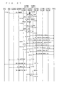
- FIG. 26 is a diagram showing a sequence of a HO process and a TAU process in a case where an RN performs inter-MME HO.
- FIG. 29 is a flowchart showing a processing procedure of a process in which an RN judges whether HO is intra-MME HO or inter-MME HO.
- the reception process of the base station 72 is executed as follows. Radio signals from one or a plurality of user equipments 71 are received through the antenna 908 . The received signal is converted from a radio reception frequency into a baseband signal by the frequency converting unit 907 , and is then demodulated by a demodulating unit 909 . The demodulated data is transmitted to a decoding unit 910 and is then subjected to a decoding process such as error correction. Among the pieces of decoded data, the control data is transmitted to the protocol processing unit 903 , EPC communication unit 901 , or communication with another base station unit 902 , while the user data is transmitted to the EPC communication unit 901 and the communication with another base station unit 902 . A series of processes of the base station 72 is controlled by a control unit 911 . This means that, though not shown in FIG. 9 , the control unit 911 is connected to the respective units 901 to 910 .
- the function of the MME 73 a under discussion of 3GPP is described below (see Chapter 4.6.2 of Non-Patent Document 1).
- the MME 73 a performs access control for one or a plurality of user equipments being members of closed subscriber groups (CSGs).
- the MME 73 a recognizes the execution of paging optimization as an option.
- the user equipment that does not have a whitelist (including a case where the whitelist is empty in the present invention) is not allowed to access the CSG cell but is allowed to access the non-CSG cell only. Meanwhile, the user equipment which has a whitelist is allowed to access the CSG cell of the CSG-ID with which registration has been performed as well as the non-CSG cell.
- the MME for RN 1301 is an MME that manages the RN 1304 .
- the MME for UE 1302 is an MME that manages the MME for UE 1303 .
- the MME for RN 1301 and MME for UE 1302 may be configured in the same MME 1300 .
- FIG. 13 shows a case in which the MME for RN 1301 and MME for UE 1302 are configured in the same MME 1300 .
- the MME for RN 1301 and MME for UE 1302 are not required to be configured in the same MME 1300 .
- the P-GW for UE 1306 is a P-GW for the UE 1303 .
- the S-GW for UE 1307 is an S-GW for the UE 1303 .
- the moving body for example, an express bus 1406 is currently located within the coverage 1401 provided by the base station 1402 and is moving along the direction of an arrow 1400 .
- An RN 1407 is installed in the express bus 1406 .
- Passengers riding in the express bus 1406 carry UEs 1403 to 1405 .
- the UEs 1403 to 1405 are installed in the express bus 1406 .
- the MME that has received the TAU request performs the process of managing the UE mobility and then transmits the TAI list, by including the TAI of the TA to which the target eNB belongs in the TAI list, to the UE.
- An RN 1508 is located in the coverage 1517 provided by the RN 1508 .
- a UE 1509 is served by the RN 1508 .
- the first TA 1534 and second TA 1535 are managed by the first MME 1520 .
- the third TA 1518 and fourth TA 1519 are managed by the second MME 1501 .
- the MME manages the TAI list of a UE for mobility management of the UE.
- the TAI list is shared between the UE and MME.
- the TAIs in the TAI list are the TAIs of the TAs managed by the MME that manages this TAI list.
- the eNB (hereinafter, also referred to as a “source eNB”), to which the RN 1508 has been connected before moving, is the fourth eNB 1525 , and the MME (hereinafter, also referred to as a “source MME”) connected to the source eNB is the first MME 1520 .
- FIG. 16 shows a case in which the RN 1508 moves along the arrow 1500 .
- the TA to which the RN 1508 before moving belongs is the TA to which the fourth eNB 1525 being a source DeNB for the RN belongs.
- the TA to which the RN 1508 before moving belongs is a first TA 1601 .
- the first TA 1601 is managed by the first MME 1520 .
- the first, fourth, and fifth eNBs (cells) 1522 , 1525 , and 1526 belong to the first TA 1601 .
- Step ST 1708 the RN changes the TAI of the own RN to the TAI received from the target DeNB.
- Step ST 1709 the RN performs the system information modification (SI modification) process on the UE being served thereby.
- the RN notifies the UE being served thereby of the modification of the system information through paging.
- Step ST 1710 the RN broadcasts the TAI changed in Step ST 1708 to the UE being served thereby as the system information.
- the UE recognizes that the system information has been modified through paging and receives the system information broadcast. This enables the UE being served by the RN to receive the TAI changed if it is in the RRC_Connected state or RRC_Idle state.
- the UE being served by the RN receives the system information from the RN to recognize the TAI of the RN.
- the UE checks whether or not the TAI of the RN is included in the TAI list of the UE, and then performs the TAU process in a case where it is not included or does not perform the TAU process in a case where it is included.
- FIG. 17 shows the case in which the TAI list of the UE does not include the TAI of the RN, namely a case in which the UE performs the TAU process.
- the target MME updates the TAI list of the UE and notifies the UE of the updated TAI list.
- the UE receives the updated TAI list from the target MME.
- Mobile and fixed modes may be provided as RN modes.
- One RN may support both modes. In a case where one RN can support both modes, the RN operates in the mobile mode in one case and operates in the fixed mode in the other case.
- the mobile RN may operate in the mobile mode and the fixed RN may operate in the fixed mode.
- the mobile RN may operate in the mobile mode or the fixed mode.
- the TA to which the RN operating in the fixed mode belongs and the TA to which the RN operating in the mobile mode may differ from each other. This allows for TA management according to the operating mode of the RN.
- the TA to which the mobile RN belongs can be managed by the MME but the TAI of the mobile RN is not included in the TAI list managed by every MME.
- FIG. 19 is a diagram showing an architecture of a mobile communication system including an RN in a case where the transmission and reception of the information regarding the TA are performed between the MME for UE and the MME for RN.
- the configuration shown in FIG. 19 is similar to the configuration shown in FIG. 13 , and thus, the corresponding parts are denoted by the same reference symbols and common description is omitted.
- an IF 1901 is provided between the MME for RN 1301 and the MME for UE 1302 .
- the MME for RN 1301 and the MME for UE 1302 transmit and receive the information regarding the TA via the IF 1901 .
- Step ST 2207 the TAU process of the RN is performed as required.
- the TAU process is performed in a case where the TAI of the target DeNB is not included in the TAI list of the RN.
- This TAU process enables the target MME to perform mobility management. After that, the process moves to Step ST 2208 .
- Step ST 2504 the MME for RN searches for the TAI in the TAI list (TAI list_RN) of the RN having the RN identity, and obtains an eNB identity in the TAI.
- the MME for UE can recognize to which DeNB the RN to be connected with the UE is connected and thus can perform the mobility management of the UE being served by the RN. This allows for communication between the UE and core network.
- the second embodiment above has disclosed the method in which with a TAI of an RN being fixed, the information regarding the TA is transmitted and received between the MME for UE and the MME for RN.
- This modification discloses the method of transmitting and receiving the information regarding a UE between a target MME and a source MME.
- the MME for UE is provided with a function of managing a TA to which a mobile RN belongs. Also, the MME for RN is provided with a function of managing a TAI list of a mobile RN.
- the HO process and TAU process of the RN are required.
- the UE being served by this RN does not need the HO process but needs the TAU process.
- the method disclosed here is also applicable to the first embodiment described above. It suffices that the MME to be connected with the target DeNB for the RN manages the TAI of this RN.
- a predetermined signal is used as a trigger for activating the TAU process of a UE being served by an RN that has moved.
- the predetermined signal includes a message such as a TAU request message or a TAU completion message.
- Disclosed below is a specific example of the method of transmitting and receiving the information regarding a UE being served by an RN between the source MME and target MME in the HO process and TAU process by the RN.
- FIG. 26 is a diagram showing a sequence of the HO process and TAU process in a case where an RN performs inter-MME HO. Described below is a case in which the TAU process of a UE being served by a mobile RN is activated, triggered by the receipt of a TAU request message from the RN by the target MME.
- Step ST 2602 the RN moves. As a result, the communication quality between the RN and DeNB deteriorates.
- Step ST 2616 the source MME for RN transmits a context release signal to the source DeNB.
- the source DeNB that has received the context release signal releases a context and, in Step ST 2617 , transmits a context release completion signal to the source MME for RN.
- the target MME for RN transmits the TAU request signal of the UE being served by the RN to the target MME for UE (t-MME for UE).
- the target MME for RN transmits an identity of the UE being by the RN together with the TAU request signal to the target MME for UE.
- the identity of the UE being served by the RN may be transmitted to the target MME for UE as another signal, not being included in the TAU request signal. Alternatively, an identity of the RN may be transmitted together.
- the target MME for UE that has received the TAU request signal of the UE being served by the RN in Step ST 2703 activates the TAU process of the UE that is represented by the identity of the UE being served by the RN, which has been received together.
- Step ST 2706 the source MME for RN transmits a context response signal to the target MME for RN.
- Step ST 2707 the source MME for UE transmits a UE context response signal to the target MME for UE.
- the process of transmitting the TAU acceptance signal to the UE in Step ST 2719 and the process of transmitting the TAU completion signal from the UE in Step ST 2721 may be omitted.
- the TAU acceptance message to the UE to be notified by the TAU acceptance signal in Step ST 2719 and the TAU completion message from the UE notified by the TAU completion signal in Step ST 2721 may be omitted.
- the UE being served by the RN does not need to transmit a TAU request signal by the method disclosed in this modification. This can solve a problem that when the RN moves so as to straddle TAs, UEs being served by this RN simultaneously generate a TAU request signal. Accordingly, signaling load can be reduced.
- the UE that has been notified that the TAU process has failed may disconnect the communication with the RN to perform a cell reselection process.
- the UE activates the TAU process by itself and transmit a TAU request signal to the target MME via the RN.
- the UE performs a normal TAU process. This allows the UE to perform the process to be performed in a case where a normal TAU process fails, even if it fails again in connection with the target MME. This enables the UE to select other cell such as an eNB, DeNB, or RN, allowing for communication via the selected cell.
- the method described above may be applied as the operation of the UE notified that the TAU process has failed.
- the method described above may also be applied as the method of notifying a UE from an RN. This enables, also in a case where the UE being served by the RN that has moved is restricted from accessing a target MME, the UE to select other cell such as eNB, DeNB, or RN, allowing for communication via the selected cell such as eNB, DeNB, or RN.
- the TAU acceptance message may be omitted.
- a TAI of an RN remains unchanged if the RN moves and a TAI list of a UE being served by the RN includes only the TAI of the RN. This allows for omission of the TAI list of the UE.
- the method of performing a data forwarding process of a UE is disclosed.
- the data forwarding process of the UE may be performed during the HO process of the RN.
- a specific example of the data forwarding process of the UE is described below.
- the HO process of the RN is preferably continued if the HO process of the UE has failed.
- the HO process is preferably completed.
- the HO process of the UE is performed again.
- the number of times the HO process is repeated may be limited.
- a time limit may be set for allowing the UE to perform the HO process such that the UE can perform the HO process again within the time limit. After the time limit has passed, the UE may be prohibited from performing the HO process again such that the prohibited UE is notified that the HO process has failed.
- the method disclosed in the second embodiment is applied such that the TAI of the RN is fixed and, only in a case where the RN has performed inter-MME HO, the method disclosed in the first embodiment is applied such that the TAI of the RN is made identical to the TAI of the target DeNB.
- the RN judges based on the GUTI notified from the target MME when it performs HO.
- the MME may be a source MME or target MME.
- the identity indicating whether or not HO is inter-MME HO is provided, and the MME notifies the RN that performs the HO process of this identity.
- Step ST 2904 the RN judges that the target MME is identical to the source MME and that intra-MME HO has been performed. After the process of Step ST 2904 , the RN moves to Step ST 2906 .
- Step ST 2906 the RN does not change the TAI of the own RN but follows the method of the second embodiment described above.
- the TAU request signal to be transmitted from the RN to the target MME for RN includes the information indicating whether or not to transmit and receive the information regarding a UE being served by an RN between the source MME and target MME. This allows the RN to request the MME to perform the TAU process of the UE being served thereby.
- the method disclosed in this embodiment can prevent the control from becoming complicated, reducing a signaling load. Further, the target MME and source MME can recognize a UE being served by an RN and configure and manage the TAI list of the UE, allowing for communication between the UE and core network.
- the operation is as described with reference to FIG. 13 .
- the operation in the case where the RN 1304 is a mobile RN is disclosed below.
- the operation is as described with reference to FIG. 13 .
- communications are performed among the mobile RN 1304 , DeNB 1305 , MME for RN 1301 , and S-GW/P-GW functionality of the DeNB 1305 .
- the MME that manages the TAI of the DeNB is an MME for RN, and thus, the MME for RN suitably manages the mobility of the mobile RN.
- the Uu interface 1314 is used in the communication between the UE 1303 and mobile RN 1304 .
- the S1 interface 3001 is used in the communication between the mobile RN 1304 and m-MME for UE 3003 via the S1 proxy functionality of the DeNB 1305 .
- the S11 interface 3002 is used in the communication between the m-MME for UE 3003 and S-GW for UE 1307 .
- FIG. 31 is a diagram for describing the TA to which a mobile RN belongs and the TA to which a UE being served by the mobile RN belongs.
- the configuration shown in FIG. 31 is similar to the configuration shown in FIG. 15 , and thus, the corresponding parts are denoted by the same reference symbols and common description is omitted.
- FIG. 31 shows a case in which an RN 3106 moves along an arrow 3100 .
- the RN 3106 is located in a coverage 3107 provided by the RN 3106 .
- the TA to which the RN 3106 before moving belongs is a fifth TA 3108 .
- a UE 3109 being served by the RN 3106 moves as the RN 3106 moves.
- the RN 3106 before moving is connected to the sixth DeNB 1527 .
- the sixth DeNB 1527 is connected to the first MME 1520 .
- the RN 3106 After the RN 3106 moves along the arrow 3100 , the RN 3106 is connected to the tenth DeNB 1505 .
- the tenth DeNB 1505 is connected to the second MME 1501 .
- the TA to which the RN 3106 after moving belongs remains unchanged, which is the fifth TA 3108 .
- the fifth TA 3108 being a TA to which the RN 3106 belongs is managed by an m-MME 3102 .
- the m-MME is connected to all the DeNBs that support the mobile RN. In the example shown in FIG. 31 , the m-MME 3102 is connected to the DeNBs 1522 to 1527 and 1502 to 1507 .
- the mobile RN 3106 moves between different MMEs from the sixth DeNB 1527 to the tenth DeNB 1505 .
- the mobile RN still belongs the same TA.
- the TAI of the RN remains unchanged.
- the TAI is still the TAI of the fifth TA 3108 .
- a DeNB to be connected with the mobile RN is changed, and thus, the HO process of the mobile RN is activated.
- the TA to which a DeNB belongs varies, that is, the TAI of the DeNB varies, and thus, the mobile RN activates the TAU in the HO.
- the method disclosed in this embodiment causes no problem if the TAU process of the UE is not performed.
- an m-MME that manages only the TA to which the mobile RN belongs is provided. This allows the m-MME to manage the TAI of the mobile RN, to thereby manage the mobility of the UE being served by the mobile RN. In other words, if the mobile RN moves between different DeNBs, the m-MME being the MME that manages the mobility of the UE being served by the mobile RN remains unchanged. Therefore, if the TAU process of the UE being served by the mobile RN is not performed, the m-MME can continuously manage the mobility of the UE, without any problem.
- the provision of an m-MME for each group of the mobile RNs can limit the DeNBs to be connected with each m-MME. This eliminates the need for connecting one m-MME with an enormous number of DeNBs.
- the DeNB that supports a mobile RN is not connected to the m-MME, the mobility of the UE being served by the RN is not managed by the m-MME.
- the following three are disclosed as the methods of solving this problem.
- the MME that manages the TAI of the UE being served by this RN is an m-MME and is not changed. This eliminates the need for performing the TAU process of the UE. As a result, the problem that a large number of TAUs occur simultaneously, which is caused in the methods disclosed in the first to third embodiments above, can be solved. Further, it is not required to exchange information between the source MME and target MME. This can prevent the TAU process from becoming complicated and reduce a signaling load.
- the MME for UE 1302 and m-MME for UE 3203 are configured in the same MME 3200 .
- the MME for RN 1301 , MME for UE 1302 , and m-MME for UE 3203 may be configured in the same MME.
- the mobile RN 1304 operates as an eNB for UE
- communications are performed among the UE 1303 , mobile RN 1304 , S1/X2 proxy functionality of the DeNB 1305 , m-MME for UE 3203 , S-GW for UE 1307 , and P-GW for UE 1306 .
- the operation in this case is also identical to the operation described with reference to FIG. 30 .
- FIG. 33 is a diagram for describing a TA to which a mobile RN belongs and a TA to which a UE being the mobile RN belongs in the first modification of the fourth embodiment.
- the configuration shown in FIG. 33 is similar to the configuration shown in FIG. 15 , and thus, the corresponding parts are denoted by the same reference symbols and common description is omitted.
- the RN 3305 is located in a coverage 3307 provided by the RN 3305 .
- a TA to which the RN 3305 before moving belongs is a fifth TA 3308 .
- a UE 3306 being served by the RN 3305 moves as the RN 3305 moves.
- the TAI list of the UE being served by the mobile RN and the TAI list of the UE being served by the fixed RN, eNB, or DeNB are managed by different MMEs.
- the TAI list of the UE being served by the mobile RN is managed by the m-MME for UE.
- the TAI list of the UE being served by the fixed RN, eNB, or DeNB is managed by the MME for UE. Specific description is given with reference to FIG. 33 .
- the TAI list of the UE 3306 being served by the mobile RN 3305 before moving and the TAI lists of the UEs being served by first to sixth DeNBs 1522 to 1527 are managed by different MMEs. Specifically, the TAI list of the TIE 3306 being served by the mobile RN 3305 is managed by the first m-MME 3301 being an m-MME for UE. The TAI lists of the UEs being served by the first to sixth DeNBs 1522 to 1527 are managed by the first MME 1520 being an MME for UE.
- the HO process and TAU process of the mobile RN are performed.
- the HO process and TAU process of the UE being served by the mobile RN are not performed.
- the TAU process of the UE is necessary. This is because the MME is changed, and accordingly, the TA managed by the target MME differs from the TA managed by the source MME.
- the methods disclosed in the first to third embodiments above can be used as the method of performing the TAU process of the UE.
- the information is exchanged between the MME for RN and the m-MME for UE by means of the interface 3204 shown in FIG. 32 .
- the TAU process is activated from the UE.
- This modification discloses another configuration of the MME that manages the TAI of the mobile RN.
- the MME for mobile RN is configured in a predetermined DeNB, specifically, an MME to which a P-DeNB belongs.
- the MME to which the P-DeNB belongs may also function as the MME for mobile RN.
- the mobile RN 1304 operates as an eNB for a UE
- communications are performed among the UE 1303 , mobile RN 1304 , S1/X2 proxy functionality of the DeNB 1305 , MME for UE 1302 to which the functions of the MME for mobile RN are added, S-GW for UE 1307 , and P-GW for UE 1306 .
- FIG. 34 is a diagram for describing a TA to which a mobile RN belongs and a TA to which a UE being served by the mobile RN belongs in the second modification of the fourth embodiment.
- the configuration shown in FIG. 34 is similar to the configuration shown in FIG. 15 , and thus, the corresponding parts are denoted by the same reference symbols and common description is omitted.
- the fourth DeNB 1525 is a P-DeNB.
- the first to twelfth DeNBs 1522 to 1527 and 1505 to 1507 are DeNBs that support a mobile RN.
- the first MME 1520 to which the P-DeNB 1525 belongs is connected to all the DeNBs 1522 to 1527 and 1505 to 1507 by the S1 interfaces 1521 and S1 interfaces 3405 .
- the TAI list of the UE being served by the mobile RN and the TAI list of the UE being served by the fixed RN, eNB, or DeNB may be managed by the same MME. Specifically, the TAI list of the UE being served by the mobile RN and the TAI list of the UE being served by the fixed RN, eNB, or DeNB are managed by the MME for UE 1520 to be connected to the P-DeNB.
- the HO process and TAU process of the mobile RN 3401 are performed.
- the HO process and TAU process of the UE 3402 being served by the mobile RN 3401 are not performed.
- the method disclosed in this modification does not need the TAU process of the UE 3402 being served by the mobile RN.
- the MME that manages the TAI of the UE 3402 being served by the RN 3401 is still the first MME 1520 and is not changed.
- the TAU process from the UE is not activated.
- the mobile RNs are subjected to grouping.
- the DeNBs to be supported per group are limited.
- the DeNBs to be connected with the MME can be limited.
- a P-DeNB may be set for each of the groups.
- the P-DeNB may be determined in advance per group.
- One or a plurality of P-DeNBs may be provided. Accordingly, the management of the TAIs can be unified for each of the groups, making it easy to maintain and manage the TAIs as a network, not limited to the MME.
- Grouping of mobile RNs may be performed, for example, per service, such as a group to be installed in a car of XX bullet train and a group to be installed in a car of YY bullet train.
- the method disclosed in the fourth embodiment described above is applicable as the method of taking a measure against the case in which a DeNB that supports a mobile RN is not connected to an MME to be connected to a P-DeNB.
- the method disclosed in this modification can avoid a situation in which the MME needs to be connected to all DeNBs. It suffices that the MME to be connected to the P-DeNB is connected to the DeNB within the moving range of the mobile RN having the TAI of the P-DeNB. This makes it easy to construct a communication system, resulting in the cost of constructing the communication system.
- the RN When an RN has moved, some of the UEs being served by the RN move together with the RN and the others remain at the original locations.
- the MME has to recognize the UEs that have moved together with the RN. For example, in the method disclosed in the second embodiment described above, the RN notifies the MME for RN of the identity of the UE being served by the RN. Alternatively, in the method disclosed in the first modification of the second embodiment described above, the RN notifies the target MME for RN of the identity of the UE being served by the RN. The MME for RN notifies the MME for UE of the identity of this UE. For this notification, the RN or MME needs to recognize which UE has moved together with the RN. Specifically, the RN or MME needs to recognize the identity of the UE that has moved together with the RN.
- the RN and MME for UE can both judge whether the UE has moved outside of the cell through the HO process or remains in the cell.
- the RN can notify the MME for RN of the identity of the UE being served by the RN, which has been disclosed in the second embodiment and the first modification of the second embodiment described above.
- the MME for UE may recognize and judge the identity of the UE being served by the RN.
- the RN does not recognize the UE in the RRC_Idle state that is being served by the own cell.
- the MME cannot recognize by which cell the UE in the RRC_Idle state is served and can only recognize the above within the range of the cell in the TAI list of the UE.
- the RN and MME both cannot judge whether the UE has moved outside of the cell or remains in the cell if the UE has moved within the cell range of the TAI list of the UE.
- FIG. 35 is a diagram for describing cases in which a UE in the RRC_Idle state moves and does not move together with a mobile RN.
- FIG. 35 shows a case in which an RN 3511 moves along an arrow 3500 .
- Part (a) of FIG. 35 is a diagram showing a state of a mobile communication system before the RN 3511 moves
- part (b) of FIG. 35 is a diagram showing a state of the mobile communication system after the RN 3511 has moved.
- a DeNB 3507 is located in a coverage 3514 provided by a first DeNB 3507 .
- a first TA 3505 to which the first DeNB 3507 belongs is managed by a first MME 3501 .
- a second DeNB 3508 is located in a coverage 3516 provided by the second DeNB 3508 .
- a second TA 3506 to which the second DeNB 3508 belongs is managed by a second MME 3502 .
- the first MME 3501 and first DeNB 3507 are connected by an S1 interface 3503 .
- the second MME 3502 and second DeNB 3508 are connected by an S1 interface 3504 .
- the RN 3511 is located in a coverage 3510 provided by the RN 3511 .
- a third TA 3509 to which the RN 3511 before moving belongs is managed by the first MME 3501 .
- a first UE 3512 and a second UE 3513 , which are both in the RRC_Idle state, are served by the RN 3511 .
- the TA to which the RN 3511 after moving belongs is not changed from that before moving and is the third TA 3509 .
- the third TA 3509 to which the RN 3511 after moving belongs is managed by the second MME 3502 .
- the second UE 3513 remains at an original location and is in the RRC_Idle state to be served by the first DeNB 3507 .
- the first UE 3512 moves together with the RN 3511 and is in the RRC_Idle state to be served by the RN 3511 .
- the first UE 3512 that moves together with the RN 3511 is still being served by the RN 3511 .
- the first UE 3512 judges that the TAI of the RN 3511 has already been located in the TAI of the own TA list and does not activate the TAU process.
- the first MME 3501 recognizes that the UE is located in the cell within the TAI list of the UE.
- the second UE 3513 that does not move together with the RN 3511 gets out of the coverage 3510 of the RN 3511 , moves to the coverage 3514 of the first DeNB 3507 , and reselects the first DeNB 3507 as a cell.
- the TAI of the DeNB and the TAI of the RN are prohibited from being included in the same TAI list, and thus, the TAI list of the second UE 3513 has no TAI of the first TA 3505 to which the first DeNB 3507 belongs.
- the second UE 3513 accordingly activates the TAU process for the first MME 3501 .
- the TAU process of the second UE 3513 is performed by the first MME 3501 .
- the first MME 3501 can recognize whether or not the second UE 3513 that has not moved together with the RN 3511 and remained at its location is located in the TA managed by the own MME. Even if the DeNB to which the UE is connected varies and a cell is reselected between the different MMEs, similarly, the target MME and source MME can both recognize whether or not this UE is located in the TA managed by the own MME. The source MME and target MME can accordingly both recognize which UE has remained at an original location or moved together with an RN. This allows for the UE to communicate with the core network.
- an MME avoids including the TAI of the RN and the TAI of other type of cell in the same TAI list of the UE.
- FIG. 36 is a diagram showing a sequence when an RN moves in a case where the TAI of the RN and the TAI of other type of cell are prohibited from being included in the same TAI list.
- Step ST 3601 a first UE#1 is in the RRC_Idle state to be served by the RN.
- a second UE#2 is in the RRC_Idle state to be served by the RN.
- Step ST 3603 the RN is RRC-connected to the first DeNB#1.
- Step ST 3605 the MME for UE manages a TAI list_UE#1 being the TAI list of the first UE#1 and a TAI list_UE#2 being the TAT list of the second UE#2.
- the TAI list_UE#1 includes a third TAI#3 being the TAI of the TA to which the RN belongs.
- the TAI list_UE#2 includes the third TAI#3.
- Step ST 3604 accordingly, the TAI list of the first UE#1 includes the third TAI#3.
- Step ST 3606 the TAI list of the second UE#2 includes the third TAI#3.
- Step ST 3609 the HO/TAU process is performed among the RN, first DeNB#1, second DeNB#2, and MME for RN.
- Step ST 3610 the RN is RRC-connected to the second DeNB#2.
- the first UE#1 remaining at the original location is being served by the first DeNB#1, and thus compares the first TAI#1 to which the first DeNB#1 belongs and the TAI in the own TAI list and judges that the first TAI#1 is not located.
- Step ST 3611 the MME for UE includes the updated TAI list_UE#1 in the TAU acceptance signal and then notifies the first UE #1 of the TAU acceptance signal. As a result, the first UE#1 updates the TAI list.
- the TAI list of the first UE#1 includes only the first TAI#1.
- the TAI list_UE#1 of the first UE#1 managed by the MME for UE includes only the first TAI#1. Meanwhile, the TA to which the second ITE#2 belongs remains unchanged, which is the third TAI#3, and thus, the MIME for UE does not change the TAI list_UE#2.
- the first DeNB#1 checks the TAI list_UE#1 in the paging message.
- the TAI list_UE#1 includes the first TAI#1 of the own cell, and thus, in Step ST 3616 , the first DeNB#1 transmits the paging signal to the first UE#1 being served thereby.
- the MME for UE transmits the paging signal to the RN belonging to the third TAI#3 with the use of the TAI list_#UE2 in Step ST 3613 .
- the RN is connected to the second DeNB#2, and thus, the MME for UE transmits the paging signal to the RN via the second DeNB#2 in Steps ST 3617 and ST 3618 .
- the DeNB to be connected with the RN is changed in the HO/TAU process of the RN in Step ST 3609 . It suffices that the MME for UE obtains from the MME for RN the information of the DeNB connected with the RN.
- Step ST 3618 the second DeNB#2 that has received the paging message from the MME for UE in Step ST 3617 transmits this paging message to the RN by the proxy functionality.
- the RN that has received the paging message checks the TAI list_UE#2 in the paging message.
- the TAI list_UE#2 includes the third TAI#3 of the own cell, and thus, in Step ST 3619 , transmits the paging signal to the second UE#2 being served thereby.
- the MME may add this TAI to the TAI list in the TAU process of the UE.
- the MME deletes the TAI in the TAI list of the UE and includes the TAI of the other type of cell in the TAI list.
- the MME is configured so as to judge whether the TAI is the TAI of the RN or the TAI of other cell.
- TAI is the TAI of the RN or the TAI of other cell.
- the RN may notify the MME of the information indicating that the own cell is an RN.
- An operation administration and maintenance (OAM) may notify the cell and the MME of the information indicating that the cell is an RN.
- the MME associates the information indicating that the cell is an RN with the identity of the cell being a target for this information, and manages the associated ones.
- the MME may notify the HSS of the information indicating that the cell is an RN.
- the HSS associates the information indicating that the cell is an RN and the identity of the cell being a target for the information and manages the associated ones. This enables the MME and HSS to recognize whether or not the cell is an RN, allowing for management as the RN.
- the MME manages two TAI lists for one UE.
- the two TAI lists may be the TAI list for mobile RN and the TAI list for other cell. A specific example thereof is disclosed below.
- Step ST 3703 the RN is RRC-connected to the first DeNB#1.
- Step ST 3709 the HO/TAU process is performed among the RN, first DeNB#1, second DeNB#2, and MME for RN.
- Step ST 3710 the RN is RRC-connected to the second DeNB#2.
- Step ST 3701 the first UE#1 is in the RRC_Idle state to be served by the RN.
- Step ST 3702 the second UE#2 is in the RRC_Idle state to be served by the RN.
- Step ST 3711 the MME for UE manages two TAI lists for the first UE#1, specifically, the TAI list_UE#1 (RN) and TAI list_UE#1 (other). Similarly, in Step ST 3711 , the MME for UE manages two TAI lists for the second UE#2, specifically, the TAI list_UE#2 (RN) and TAI list_UE#2 (other).
- Step ST 3802 the first UE#1 performs the process of establishing the RRC connection with the first DeNB#1, to thereby being RRC-connected therewith. Then, the first UE#1 shifts to the RRC_connected state.
- Step ST 3813 the MME for UE deletes or empties the TAI list_UE#1 (RN) of the first UE#1.
- the TAI list of the first UE#1 has been changed, and accordingly, in Steps ST 3805 and ST 3804 , the MME for UE transmits a TAI list update message indicative of the updated TAI list to the first UE#1 via the first DeNB#1.
- the MME for UE transmits the TAI list update message, by including the updated TAI list_UE#1 therein.
- the TAI list_UE#1 includes only the first TAI#1.
- This TAI list update message may be S1 signaling.
- the first UE#1 receives the TAI list update message in Step ST 3804 and, in Step ST 3806 , updates the TAI included in the TAI list.
- the third TAI#3 is deleted and the first TAI#1 is left in the TAI list.
- the case of the second UE#2 is disclosed, which is performed by a method similar to that of the first UE#1.
- Step ST 3807 the second UE#2 performs the process of establishing RRC connection with the RN, to thereby being RRC_connected therewith. Then, the second UE#2 changes to the RRC_Connected state.
- Step ST 3807 the second UE#2 that has changed to the RRC_connected state in Step ST 3807 transmits a service request to the RN.
- Step ST 3808 the RN transmits the service request to the MME for UE.
- the RN includes at least any one of the cell identity of the own cell and the TAI of the own cell in the service request of the second UE#2.
- the transmission from the RN to the MME for UE is performed via the second DeNB#2, and the second DeNB#2 serves as a proxy to the MME for UE.
- the MME for UE that has received the service request recognizes that the second UE#2 is served by the RN. This allows the MME for UE to recognize that the second UE#2 is not served by the first DeNB#1.
- Step ST 3809 the MME for UE deletes or empties the TAI list_UE#2 (other) of the second UE#2.
- the TAI list of the first UE#2 has been changed, and accordingly, in Steps ST 3810 and ST 3811 , the MME for UE transmits a TAI list update message indicative of the updated TAI list to the second UE#2 via the RN.
- the MME for UE transmits the TAI list update message, by including the updated TAI list_UE#2 therein.
- the TAI list_UE#2 includes only the third TAI#3. This TAI list update message may be S1 signaling.
- the transmission from the MME for UE to the RN is performed via the second DeNB#2, and the second DeNB#2 serves as a proxy to the RN.
- the second UE#2 receives a TAI list update message.
- the second UE#2 updates the TAI included in the TAI list.
- the first TAM is deleted and the third TAI#3 is left in the TAI list.
- FIG. 38 shows the case in which the UE changes to the RRC_connected state, which may be a case in which the UE activates the TAU, and similar effects can be achieved.
- Step ST 3709 of FIG. 37 the MME for UE may recognize the TAI of the DeNB to be connected with the RN.
- the RN that has moved from the first DeNB#1 to the second DeNB#2 is subjected to the HO process and the TAU process. These processes allow the MME for RN to recognize that the RN has been connected to the second DeNB#2.
- the MME for RN and MME for UE are configured to exchange the information regarding the DeNB connected with the RN, for example, the cell identity and a TAI to which the cell belong. This enables the MME for UE to recognize the TAI of the DeNB to be connected with the RN.
- the MME for UE may update the TAI list of the UE.
- the MME for UE that has recognized the TAI of the DeNB to be connected with the RN updates the TAI lists of the first UE#1 and second UE#2.
- the second TAI#2 is added to the TAI list_UE#1 (other) of the first UE#1.
- the second TAI#2 is added to the TAI list_UE#2 (other) of the second UE#2.
- the TAI list has been changed, and accordingly, the
- the MME for UE notifies the first UE#1 and the second UE#2 of the updated TAI lists.
- the TAI list update method disclosed in FIG. 38 may be used as the notification method.
- the TAI list includes the TAI of the second DeNB#2 to be connected with the RN.
- the UE that has moved together with the RN does not need to generate a TAU process if it has moved between the DeNB and RN. This results in a further reduction in signaling load.
- the UE is required to have only one TAI list and not required to have two TAI lists.
- the UE may have two TAI lists similarly to the TAI lists of the MME.
- the UE and MME can manage those as the same TAI list, reducing malfunctions as much as possible in the operation of the TAI list.
- the source MME and target MME both have or manage the TAI list for one UE.
- the MME may have and manage one TAI list of the UE.
- the source MME and target MME can both page the UE when an incoming call is made to the UE. Consequently, the UE can communicate with the core network.
- a specific example thereof is disclosed below.
- Step ST 3901 the first UE#1 is in the RRC_Idle state to be served by the RN.
- Step ST 3902 the second UE#2 is in the RRC_Idle state to be served by the RN.
- the RN is RRC-connected to the first DeNB#1.
- the first MME for UE is connected to the first DeNB#1.
- the first MME for UE manages the TAI lists of the first UE#1 and second UE#2.
- the TAI list_UE#1 includes the third TAI#3 of a TA to which the RN belongs and a first TAI#1 of a TA to which the first DeNB#1 belongs.
- the TAI list_UE#2 includes the third TAI#3 of the TA to which the RN belongs and first TAI#1 of the TA to which the first DeNB#1 belongs.
- the TAI list_UE#1 of the first UE#1 includes the first TAI#1 and third TAI#3.
- the TAI list_UE#2 of the second UE#2 includes the first TAI#1 and third TAI#3.
- Step ST 3907 the second UE#2 moves together with the RN.
- Step ST 3908 the RN moves from being served by the first DeNB#1 to being served by the second DeNB#2.
- the first UE#1 remains at an original location.
- Step ST 3909 the HO/TAU process is performed among the RN, first DeNB#1, second DeNB#2, first MME#1 for RN, and second MME#2 for RN.
- Step ST 3910 the RN is RRC-connected to the second DeNB#2.
- the first UE#1 remaining at the original location is served by the first DeNB#1, and thus compares the first TAI#1 to which the first DeNB#1 belongs with the TAI of the own TAI list and judges that the first TAI#1 is located. The first UE#1 accordingly does not activate the TAU.
- the TAU process of the first UE#1 is not performed, and thus, the first MME#1 for UE does not change the TAI list_UE#1.
- the TA to which the second UE#2 belongs remains unchanged, which is the third TAI#3, and thus, the first MME#1 for UE does not change the TAI list_UE#2.
- Step ST 3911 the first MME#1 for UE derives the UE including the TAI of the RN that has moved in the TAI list.
- Step ST 3911 the first MME#1 for RN notifies the first MME#1 for UE of the TAI of the RN that has moved.
- Step ST 3909 the first MME#1 for RN notifies the first MME#1 for UE of the identity of the MME being the target for the RN that has moved. This allows the first MME#1 for UE to recognize the MME being the target for the RN that has moved.
- the first MME#1 for UE detects that the TAI list_UE#1 and TAI list_UE#2 include the third TAI#3 of the RN using the TAI list.
- the first MME#1 for UE accordingly judges that the first UE#1 and second UE#2 include the third TAI#3 of the RN.
- Step ST 3912 the first MME#1 for UE notifies the second MME#2 for UE being the target for the RN of the TAI list of the UE together with the identity of the derived UE.
- the first MME#1 for UE may notify the target second MME#2 for RN of the TAI list of the UE together with the identity of the derived UE. It suffices that in that case, the target second MME#2 for RN notifies the target second MME#2 for UE of this information.
- Step ST 3913 the first MME#1 for UE continuously holds the TAI lists of the first UE#1 and second UE#2. As a result, the TAI lists of the first UE#1 and second UE#2 are possessed by both of the first MME#1 for UE and second MME#2 for UE.
- the first MME#1 for UE notifies the second MME#2 for UE being the target for the RN of the TAI list of the UE together with the identity of the derived UE.
- the second MME#2 for UE being the target for the RN may notify the source first MME#1 for UE of the information indicating that the notification of the TAI list of the UE is requested together with the identity of the derived UE.
- the first MME#1 for UE that has received this information may notify the target second MME#2 for UE of the TAI list of the UE together with the identity of the derived UE.
- the first MME#1 for UE may make a notification via the source first MME#1 for RN and the target second MME#2 for RN.
- the target MME may delete the TAI ineffective in the own MME from the TAI list of the UE. For example, in a case where the RN has performed inter-MME HO, in some cases, the target MME cannot manage the TA managed by the source MME. In such cases, the target MME deletes the TAI ineffective in the own MME, and then, updates the TAI list of the UE with the left TAI. Meanwhile, the TAI list of the UE in the source MME is not changed and is left as it is.
- the TAI list of the UE that is managed by the target MME is appropriately updated and does not include an unnecessary TA. This prevents the transmission of a paging signal also to an unnecessary cell, resulting in a reduction in signaling load.
- the TAI list_UE#1 of the first UE#1 includes only the third TAI#3 and the TAI list_UE#2 of the second UE#2 includes only the third TAI#3.
- the TAI lists of the first UE#1 and second UE#2 are changed in the second MME #2, which may be managed only in the MME and may be not notified to the UEs.
- the HSS that has been requested the information of the first UE#1 notifies the source node of the identities of the first MME #1 and second MME #2. Consequently, the MMEs of the first MME #1 and second MIME #2 are notified of the incoming call signal to the first UE#1.
- the second MME#2 for UE that has received the incoming call signal in Step ST 3921 transmits the paging signal using the TAI list_UE#1 of the first UE#1 in Step ST 3916 .
- the second MME#2 for UE transmits the paging signal to the second DeNB#2.
- the second DeNB#2 transmits the paging signal to the RN that belongs to the third TAI#3 included in the TAI list_UE#1.
- the second DeNB#2 proxies the paging signal to the RN.
- Step ST 3928 the first MME#1 for UE further transmits the paging signal also to the RN that belongs to the third TAI#3 included in the TAI list_UE#2.
- the RN has been moved and is not connected to the first DeNB#1, and thus, the first DeNB#1 cannot proxy the paging signal to the RN.
- the paging signal is not transmitted to the RN.
- the second MME#2 for UE that has received an incoming call signal in Step ST 3929 transmits a paging signal using the TAI list_UE#2 of the second UE#2 in Step ST 3916 .
- the second MME#2 for UE transmits the paging signal to the second DeNB#2.
- the second DeNB#2 transmits the paging signal to the RN that belongs to the third TAI#3 included in the TAI list_UE#2.
- the second DeNB#2 proxies the paging signal to the RN.
- the RN checks the TAI list of the second UE#2 in the paging message.
- the TAI list of the second UE#2 includes the third TAI#3 of the own cell, and thus, in Step ST 3932 , the second DeNB#2 transmits the paging signal to the second UE#2.
- the second UE#2 is served by the RN but is not served by the first DeNB#1, and thus, the second UE#2 does not receive the paging signal from the first DeNB#1 in Step ST 3927 .
- the second UE#2 can receive the paging signal from the RN in Step ST 3932 .
- the method disclosed in this modification allows the MME to perform the incoming call process via a DeNB or RN to be connected with the UE even if the UE is in the RRC_Idle state.
- the UE can accordingly communicate with the core network.
- the MME can perform the incoming call process via the DeNB or RN to be connected with the UE.
- the UE can accordingly communicate with the core network.
- the TAI of the RN and the TAI of other cell can be included in the same TAI list, thereby preventing a situation in which the UE repeatedly moves between the RN and DeNB or between neighbour eNBs and the TAU repeatedly occurs. This results in a reduction in signaling load.
- the UE does not need to recognize that there are two TAI lists. Thus, the operation of the UE is not required to be changed from the conventional one, avoiding control from becoming complicated. Also in a case where the RN performs inter-MME HO, the UE can communicate with the core network.
- the process of deleting the unnecessary TAI list of the MME is provided.
- the unnecessary TAI list of the UE of any one of the source MME and target MME becomes unnecessary
- the unnecessary TAI list of the UE of one MME is deleted.
- the other TAI list is deleted when the TAU occurs next or when the UE next changes to the RRC_Connected state.
- the unnecessary location information of the UE in the HSS may be deleted. A specific example thereof is disclosed below.
- FIG. 40 is a diagram showing a sequence in which an MME deletes one TAI list when the UE changes to the RRC_Connected state.
- Step ST 3901 the first UE#1 is in the RRC_Idle state to be served by the RN.
- Step ST 3902 the second UE#2 is in the RRC_Idle state to be served by the RN.
- Step ST 3910 the RN is RRC-connected to the second DeNB#2.
- the first MME#1 for UE manages the TAI list_UE#1 of the first UE#1 and the TAI list_UE#2 of the second UE#2.
- the TAI list_UE#1 includes a third TAI#3 of a TA to which the RN belongs and a first TAI#1 of a TA to which the first DeNB#1 belongs.
- the TAI list_UE#2 includes the third TAI#3 and first TAI#1.
- the second MME#2 for UE manages the TAI list_UE#1 of the first UE#1 and the TAI list_UE#2 of the second UE#2.
- the TAI list_UE#1 includes the third TAI#3 of the TA to which the RN belongs.
- the TAI list_UE#2 includes the third TAI#3.
- Step ST 3904 the TAI list_UE#1 of the first UE#1 includes the first TAM and third TAI#3.
- the TAI list_UE#2 of the second UE#2 includes the first TAI#1 and third TAI#3.
- the RN includes at least any one of the cell identity of the own cell and the TAI of the own cell in the service request of the second UE#2.
- the transmission from the RN to the second MME#2 for UE is performed via the second DeNB#2, and the second DeNB#2 serves as a proxy to the second MME#2 for UE.
- Step ST 4007 the first MME#1 for UE that has received the signal for requesting the deletion of the TAI list_UE#2 deletes the TAI list_UE#2 of the second UE#2.
- the TAI list of the second UE#2 is deleted from the TAI lists in the first MME#1 for UE.
- Step ST 4008 the TAI list_UE#1 of the first UE#1 is managed as it is in the first MME#1 for UE.
- Step ST 4010 the first UE#1 performs the process of establishing the RRC connection with the first DeNB#1, to thereby being RRC-connected therewith. Then, the first UE#1 changes to the RRC_Connected state.
- Step ST 4010 the first UE#1 that has changed to the RRC_connected state in Step ST 4010 transmits a service request to the first DeNB#1.
- Step ST 4009 the first DeNB#1 transmits the service request to the first MME#1 for UE.
- the first DeNB#1 includes at least any one of the cell identity of the own cell and the TAI of the own cell in the service request of the first UE#1.
- the first MME#1 for UE that has received the service request judges that the first UE#1 is served by the first DeNB#1.
- the first MME#1 for UE accordingly recognizes that the first UE#1 is not served by the RN.
- the first MME#1 for UE transmits, to the second MME#2 for UE, a TAI list deletion request signal, specifically, a signal for requesting the deletion of the TAI list_UE#1 of the first UE#1.
- the information for requesting the deletion of a TAI list is included in the TAI list deletion request signal together with the identity (UE-ID) of the UE whose TAI list is deleted.
- Step ST 4013 the second MME#2 for UE that has received the signal for requesting the deletion of the TAI list_UE#1 deletes the TAI list_UE#1 of the first UE#1.
- the TAI list of the first UE#1 is deleted from the TAI lists in the second MME#2 for UE.
- the TAI list of the first UE#1 is not changed in the first MME#1 for UE, and thus, the first MME#1 for UE does not need to transmit the updated TAI list to the first UE#1.
- the TAI list of the second UE#2 is changed in the second MME#2 for UE, and thus, in Step ST 4015 , the second MME#2 for UE transmits the updated TAI list to the RN via the second DeNB#2.
- Step ST 4016 the RN transmits the updated TAI list to the second UE#2.
- the updated TAI list_UE#2 is included in a TAI list update message and then is transmitted.
- the TAI list_UE#2 includes only the third TAI#3.
- the TAI list update message may be S1 signaling.
- Step ST 4017 the second UE#2 that has received the TAI list update message in Step ST 4016 updates a TAI included in the TAI list.
- Step ST 4017 the first TAM is deleted and the third TAI#3 is left in the TAI list.
- the method of deleting the unnecessary location information of the UE in the HSS is disclosed.
- the unnecessary TAI list of the MME and location information in the HSS are deleted, which avoids the MME and HSS from continuously holding the unnecessary information, resulting in a reduction in unnecessary paging to a cell. This can reduce a signaling load. Also, the storage capacities of the MME and HSS can be reduced. This results in reductions in manufacturing costs of the MME and HSS.
- This modification discloses another method for solving the problem described in the fifth embodiment.
- the RN After moving, the RN performs polling on the UEs to be served thereby, which are in the RRC_Idle state.
- the information for polling may be provided to the system information.
- the information for polling may be a minimum information amount, one bit. For example, polling is necessary when the information for polling is “1” or polling is not necessary when the information for polling is “0”.
- the RN sets the information for polling to “0” and broadcasts this.
- the method of notifying the UEs being served thereby is similar to that in a case where the RN performs polling.
- the RN may perform polling on the UEs to be served thereby, which are in the RRC_Connected state. Polling may be performed for connection confirmation. For example, it can be checked whether or not an equipment or the like performing the DRX operation has not moved to other cell during DRX.
- the method disclosed in this modification is also applicable to the polling on the UEs in the RRC_Connected state.
- the information for polling may be included in the paging message. Paging allows the RN to notify the UE being served thereby of the information for polling.
- the system information does not need to be changed unlike the above-mentioned method, simplifying control of the RN and UE.
- the methods disclosed in the fifth embodiment to the third modification of the fifth embodiment described above and the method disclosed in the second embodiment or the first modification of the second embodiment described above may be used in combination.
- the MME can manage the mobility of the UE being served by the RN if the UE being served by the RN is in the RRC_Connected state or RRC_Idle state. The communication between the UE and core network is accordingly allowed.
- the method disclosed in the fifth embodiment described above and the method disclosed in the second embodiment or the first modification of the second embodiment described above are used in combination, as to the UE being served by the RN, which is in the RRC_Connected state, the method disclosed in the second embodiment or the first modification of the second embodiment described above may be applied in the HO/TAU process of the RN in Step ST 3609 of FIG. 36 .
- the first modification of the second embodiment above has disclosed the method of transmitting and receiving the information regarding a UE between a target MME and a source MME.
- the information regarding a UE being served by the RN is transmitted and received between the source MME and target MME, and thus, the method of activating the TAU process of the UE is disclosed.
- the transmission and reception of the information regarding a UE being served by an RN as well as the transmission and reception of the information regarding the RN are performed between the source MME and target MME.
- a specific example of the TAU process of the RN in this embodiment is disclosed below.
- Step ST 2704 the target MME for RN transmits a context request signal to the source MME for RN.
- the target MME for RN transmits the identity of the UE being served by the RN, and further, the identity of the RN together.
- Step ST 4102 the source MME for UE transmits the context information of the UE being served by the RN to the source MME for RN in response to the context request signal of the UE being served by the RN that has been received in Step ST 4101 .
- Step ST 4104 the source MME for RN that has received the context information of the UE being served by the RN transmits, to the target MME for RN, the context information of the UE being served by the RN together with the context information of the RN.
- Step ST 4105 the target MME for RN, which has received the context information of the UE being served by the RN together with the context information of the RN, transmits the context information acceptance success signal of the RN and the UE being served by the RN to the source MME for RN.
- Step ST 4106 the target MME for RN, which has received the context information of the UE being served by the RN together with the context information of the RN, transmits the context information of the UE being served by the RN to the target MME for UE.
- the target MME for RN transmits location update activation request information of a UE being served by an RN, together with the context information.
- the identity of the UE being served by the RN may be transmitted together.
- the RN identity may be transmitted together.
- Steps ST 2710 , ST 2712 , ST 2714 , and ST 2716 the target MME for RN that has transmitted the context information acceptance success signal of the RN and the UE being served by the RN in Step ST 4105 performs the process of updating the location of the RN.
- Step ST 2711 , ST 2713 , ST 2715 , and ST 2717 the target MME for UE that has received the location update activation request signal of the UE being served by the RN in Step ST 4106 performs the process of updating the location of the UE being served by the RN.
- Step ST 4107 the target MME for UE notifies the target MME for RN that the process of updating the location of the UE being served by the RN has been completed.
- Step ST 2718 the target MME for RN transmits a TAU acceptance signal to the RN.
- Step ST 2720 the RN transmits a TAU completion signal to the target MME for RN.
- the transmission of the TAU acceptance signal and the transmission of the TAU completion signal in Steps ST 2719 and ST 2721 are performed only in a case where there is information to be transmitted to the UE. Not the TAU acceptance signal but other S1 signaling may be used.
- the transmission and reception of the information regarding the UE being served by the RN as well as the transmission and reception of the information regarding the RN are performed between the source MME and target MME, so that the process equal to the TAU process of the UE being served by the RN is performed.
- FIG. 42 is a diagram showing a sequence in a case where the location update process of the RN and the location update process of the UE being served by the RN are both performed in the TAU process of the RN.
- the sequence shown in FIG. 42 is similar to the sequence shown in FIG. 41 , and thus, the same steps are denoted by the same step numbers and common description is omitted.
- Step ST 4201 the target MME for RN that has received the context information of the UE being served by the RN together with the context information of the RN in Step ST 4104 transmits the context information of the UE being served by the RN to the target MME for UE.
- the identity of the UE being served by the RN is transmitted together.
- the identity of the RN may be transmitted together.
- the HSS that has received the location update request signal in Step ST 4202 performs the process of updating the location of the RN and the process of updating the location of the UE being served by the RN.
- Step ST 4206 the source MME for RN, which has recognized that the location of the RN had been cancelled and the location of the UE being served by the RN had been cancelled, notifies the HSS that the cancellations of the locations of the RN and the UE being served by the RN have been completed.
- the HSS performs the process of updating the location of the RN and the process of updating the location of the UE being served by the RN.
- Step ST 4207 the HSS, which has recognized that the locations of the RN and the UE being served by the RN had been canceled, notifies the target MME for RN of a location update completion signal of the RN and the UE being served by the RN.
- Step ST 4208 the target MME for RN that has received the location update completion signal notifies the target MME for UE that the location update of the UE being served by the RN has been completed.
- the location update process of the RN and the location update process of the UE being served by the RN can be performed in the TAU process of the RN.
- signalings can be reduced between the HSS and the source MME and between the HSS and the target MME.
- the signaling load in the mobility management of the UE being served by the RN can be prevented from increasing.
- Step ST 4209 the target MME for RN transmits a TAU acceptance signal to the RN.
- the TAU acceptance signal include the information indicative of the TAU accept of the RN and the information indicating that the TAU process of the UE being served by the RN has been performed, namely indicating that the context has been forwarded and the location information has been updated and the old location information has been canceled.
- the identity of the UE being served by the RN is transmitted together.
- Step ST 4211 the UE being served by the RN receives the information indicating that the TAU process has been performed and notifies the RN that the TAU process, for example, a change of the TAI list, has been completed in the UE.
- Step ST 4212 the RN transmits the information indicating that the TAU process of the UE being served thereby has been completed to the target MME for RN, together with the completion of the TAU process of the RN.
- Steps ST 4210 and ST 4211 may be performed only in a case where there is information to be transmitted to the UE.
- the method of making a notification from the RN to the UE which has been disclosed in the first modification of the second embodiment described above, is applicable to the notification from the RN to the UE.
- the notification from the UE to the RN may be performed through dedicated signaling. For the UE in the RRC_Idle state, it suffices that the process of establishing the RRC connection with the RN is performed and a notification is made through dedicated signaling after the UE shifts to the RRC_connected state.
- a part of the process in a case where there is information to be transmitted to the UE is included in the TAU acceptance signal of the RN, resulting in a simplification of the process. This reduces a signaling amount on the core network side with respect to the RN.
- the method disclosed in this modification can suppress an increase in signaling load in the mobility management of a UE being served by an RN.
- This embodiment discloses another method for solving a problem that when an RN moves, a source MME and a target MME cannot recognize a UE being served by the RN and the communication between the UE and core network is not allowed.
- the RN transmits, to the UE being served thereby, a signal to request the activation of the TAU.
- the method (1) above is suitable for a case in which a related node has a high capability enough to simultaneously perform the TAU process of an RN and the TAU process of a UE being served by the RN.
- the TAU process of the RN and the TAU process of the UE being served by the RN are simultaneously performed, resulting in a reduction in process delay.
- the method (2) above is suitable for a case in which a related node cannot simultaneously perform the TAU process of an RN and the TAU process of a UE being served by the RN.
- the method (2) above is also applicable to a case in which a related node has low processing capability.
- an RN requests a UE being served thereby to activate the TAU in a case where the RN has performed the HO process.
- Step ST 4304 the UE that has received the TAU activation request signal from the RN activates the TAU process.
- the UE transmits the TAU request signal to an MIME to be connected to a DeNB that serves the RN after moving, specifically, the target MME for UE.
- the TAU process of the UE is performed among the UE, RN, source DeNB, target DeNB, source MME for UE, target MME for UE, source S-GW for UE, target S-GW for UE, P-GW for UE, and HSS.
- the method disclosed in this embodiment is applicable not only to a case in which the RN performs inter-MME HO but also to a case in which the RN performs intra-MME HO.
- the use of the method of this embodiment allows for application of the same procedure irrespective of whether HO is inter-MME HO or intra-MME HO. This can simplify the control for allowing communication between a UE being served by an RN and a core network.
- This embodiment discloses another method for solving a problem that when an RN moves, a source MME and a target MME cannot recognize a UE being served by the RN and communication between the UE and core network is not allowed.
- an MME for RN requests a UE being served by an RN to activate the TAU in a case where the RN performs the HO process.
- FIG. 44 is a diagram showing a sequence in which an MME for RN notifies a UE being served by an RN of a TAU activation request signal in a case where the RN performs the HO process.
- the sequence shown in FIG. 44 is similar to the sequence shown in FIG. 26 , and thus, the same steps are denoted by the same step numbers and common description is omitted.
- FIG. 44 shows a case of inter-MME HO.
- the target MME for RN transmits a TAU acceptance signal to the RN.
- the target MME for RN includes the information to request the UE being served by the RN to activate the TAU in the TAU acceptance signal. At this time, the identity of the UE being served by the RN is transmitted together.
- Step ST 4404 the RN transmits a TAU activation request signal to a UE being served thereby based on the information to request the UE being served by the RN to activate the TAU, which has been received from the target MME for RN.
- the method of making a notification from the RN to the UE, which has been disclosed in the first modification of the second embodiment described above, is applicable to the transmission of the TAU activation request signal.
- the target MME for RN may transmit, to the RN via the target MME for UE, a signal on which the information to request a UE being served by the RN to activate the TAU is mapped.
- the target MIME for RN may transmit, to the target MME for UE and to a UE being served by an RN via the RN, a signal on which the information to request the activation of the TAU is mapped.
- Step ST 4405 the UE that has received the TAU activation request signal from the RN activates the TAU process.
- the UE transmits a TAU request signal to an MME to be connected to a DeNB that serves the RN after moving, specifically, the target MME for UE.
- the TAU process of the UE is performed among the UE, RN, source DeNB, target DeNB, source MME for UE, target MME for UE, source S-GW for UE, target S-GW for UE, P-GW for UE, and HSS.
- the method disclosed in this embodiment causes the RN to move and then perform the TAU process and causes the UE being served by the RN that has moved together therewith to activate the TAU process.
- the target MME and source MME can accordingly manage the UE mobility, allowing for communication between the UE and core network.
- the method disclosed in this embodiment is applicable not only to the case in which the RN performs inter-MME HO but also to the case in which the RN performs intra-MME HO.
- the use of the method of this embodiment allows for application of the same procedure irrespective of whether HO is inter-MME HO or intra-MME HO. This can simplify the control for allowing communication between a UE being served by an RN and a core network.
- signaling loads may concentrate on the core network side with respect to the RN, and thus, a control delay and a TAU process failure may occur.
- Examples of the above are the cases disclosed in the first embodiment, seventh embodiment, and eighth embodiment described above. Examples of the above include a case in which the TAI of the RN is changed and a case in which the RN or the core network side requests the TAU from the UE being served by the RN. In order to solve such a problem, the TAU processes of the UEs being served by the RN are performed together.
- FIG. 45 is a diagram showing a sequence of a TAU process in a case where the TAU processes of the UEs being served by the RN are performed together.
- FIG. 45 shows a case of the TAU between MMEs.
- Steps ST 4501 to ST 4504 a large number of UEs being served by an RN simultaneously activate the TAU and transmit a TAU request signal to the RN.
- the RN that has received a large number of TAU request signals includes those in one TAU request message together with the identities of the UEs that have transmitted the information included in the TAU request signal.
- Step ST 4505 the RN transmits this one TAU request message to the target MME for UE.
- Step ST 4506 the target MME for UE transmits, to the source MME for UE, one signal including pieces of context require information of all the UEs being served by the RN.
- Step ST 4508 the target MME for UE transmits, to the source MME for UE, one signal including context acceptance successes of all the UEs being served by the RN.
- Step ST 4509 the target MME for UE transmits, to the HSS, one signal including pieces of location update request information of all the UEs being served by the RN.
- Step ST 4510 the HSS transmits, to the source MME for UE, one signal including pieces of location cancellation request information of all the UEs being served by the RN.
- the source MME for UE cancels the locations of all the UEs being served by the RN.
- the source MIME for UE transmits, to the HSS, a signal indicative of the location cancellation successes of all the UEs being served by the RN.
- the HSS performs the process of updating locations of all the UEs being served by the RN.
- Step ST 4512 the HSS transmits, to the target MME for UE, a location update completion signal indicative of all the UEs being served by the RN.
- the target MME for UE performs TAU processes of all the UEs being served by the RN.
- the target MME for UE transmits, to the RN, one signal including pieces of TAU accept information of all the UEs being served by the RN.
- Steps ST 4514 to ST 4517 the RN transmits the TAU acceptance signal to the UEs being served thereby.
- the UEs that have received the TAU acceptance signal perform the TAU process, for example, updates the TAI list.
- the UE transmits a TAU completion signal to the RN.
- the RN that has received a large number of TAU completion signals includes those in one TAU completion message together with the identities of the UEs that have transmitted the information included in the TAU completion signal.
- the information common to all UEs and information dedicated to a UE may be differentiated such that the common information may be included in one signal as UE common information.
- Step ST 4522 the RN transmits this one TAU completion message to the target MME for UE.
- associations may be established together with the UE identities such that every association between information and UE is evident. They may be included in one message as a list.
- the information common to all the UEs and the information dedicated to a UE may be differentiated such that the common information may be included in one signal as UE common information. This results in a reduction of information amount.
- a period which spans from a time at which an RN receives a large number of TAU request signals of UEs being served thereby to a time at which the RN transmits the one TAU request message to the target MME for RN, may be taken as a predetermined period.
- the RN receives a TAU request signal from a UE being served thereby and, after a lapse of the predetermined period, transmits a TAU request message to the target MME for UE.
- the RN transmits one TAU request message, which includes the TAU request signals from all the UEs being served by the RN that have been received during the predetermined period, to the target MME for UE.
- the predetermined period may be managed by a timer.
- the RN starts the timer upon receipt of a first TAU request signal from a UE being served thereby and, when the timer expires, transmits the TAU request signals from the UEs being served thereby that have been received so far, by including those in one TAU request message, to the target MME for UE.
- the use of the method disclosed in this embodiment prevents the concentration of signaling loads on the core network side with respect to the RN also in a case where a large number of UEs being served by an RN simultaneously activate the TAU and the TAU processes of the large number of UEs are simultaneously performed, resulting in reductions in control delays and TAU process failures.
- the UE being served by the mobile RN regularly or periodically activates the TAU.
- the TAU process of the UE being served by the mobile RN is performed, enabling the MME to perform the mobility management of the UE. This allows for communication between the UE and core network.
- the MME or mobile RN sets the TAU period of the UE and notifies the UE being served by the mobile RN of the TAU period.
- the MME may notify the mobile RN using the S1 signaling or using the S1 signaling and the signaling on a Un interface, and then, the mobile RN may notify the UE being served thereby.
- the TAU period may be included in the system information and then be broadcast or may be notified in dedicated information. Alternatively, the TAU period may be included in an RN configuration parameter and then notified.
- the TAU period for fixed mode and the TAU period for mobile mode may be set.
- the TAU period may differ from one UE to another.
- the TAU period may be set randomly from one UE to another.
- the MME or RN may set the allowable TAU period range and notify a UE being served thereby.
- the UE is configured to individually select the TAU period from the allowable TAU period range at random.
- the TAU process from the UE being served by the RN is randomly activated, preventing a control delay and a TAU process failure caused by the concentration of TAU processes among the UE, RN, and core network.
- the method disclosed in this embodiment causes the TAU process of a UE being served by the mobile RN to be performed, allowing the MME to perform the mobility management of the UE. This allows for communication between the UE and core network.
- the MME for RN and the MME for UE may be configured in the same MME.
- signaling between the MME for RN and the MME for UE is performed in the same MME, which does not require signaling between the MME for RN and the MME for UE.
- the methods disclosed in the present invention are applicable not only to the case in which the RN performs the HO process but also to the case in which the RN selects or reselects a cell. Specifically, the method is also applicable to a case in which the RN reselects a cell as a result of moving, a case in which the power of the RN is turned off and then turned on again, or a case in which the communication quality between an RN and a DeNB declines and an RN thus selects or reselects a cell after a radio link failure. Also in this case, the TAU processes of the RN and the UE being served thereby are allowed such that communication between the UE being served by the RN and the core network is allowed.
- the methods disclosed in the present invention can be appropriately carried out in combination.
- the control according to a situation of a system such as UE, relay, eNB, or MME can be performed.
- a link from a DeNB to an RN and a link from an RN to a UE are time-division multiplexed in one frequency band and a link from the RN to the DeNB and a link from the UE to the RN are also time-division multiplexed in one frequency band.
- a link from the RN to the DeNB and a link from the UE to the RN are also time-division multiplexed in one frequency band.
- other division method may be used.
- the link from the DeNB to the RN and the link from the RN to the UE may be frequency-division multiplexed in different carriers or frequency bands, and the link from the RN to the DeNB and the link from the UE to the RN may also be frequency-division multiplexed in different carriers or frequency bands.
- the methods disclosed in the first to tenth embodiments described above are applicable.
- the methods disclosed in the present invention are applicable, as a DeNB that serves a relay, not only to normal eNBs (macro cells) but also to so-called local nodes such as pico eNB (pico cell), HeNB (femtocell), node for hotzone cell, relay node, and remote radio head (RRH).
- the local node corresponds to a relay device.
- the embodiments above have described a user equipment (UE) carried by a passenger in a moving body such as an express bus or high-speed rail, not limited thereto.
- the embodiments above are also applicable to communication equipments not required to be operated by a person.
- the embodiments above are also applicable to an equipment (MTC device) for machine type communication (MTC) as the communication equipment not required to be operated by a person.
- the communication equipment corresponds to a user equipment device.
- the communication system of the present invention is also applicable to a case in which relay communication is performed in other communication system or a case in which relay communication is performed in a heterogenous communication system.
Applications Claiming Priority (3)
| Application Number | Priority Date | Filing Date | Title |
|---|---|---|---|
| JP2011173756 | 2011-08-09 | ||
| JP2011-173756 | 2011-08-09 | ||
| PCT/JP2012/070365 WO2013022067A1 (ja) | 2011-08-09 | 2012-08-09 | 移動体通信システム |
Related Parent Applications (1)
| Application Number | Title | Priority Date | Filing Date |
|---|---|---|---|
| PCT/JP2012/070365 A-371-Of-International WO2013022067A1 (ja) | 2011-08-09 | 2012-08-09 | 移動体通信システム |
Related Child Applications (1)
| Application Number | Title | Priority Date | Filing Date |
|---|---|---|---|
| US15/695,646 Continuation US10383079B2 (en) | 2011-08-09 | 2017-09-05 | Mobile communication system |
Publications (2)
| Publication Number | Publication Date |
|---|---|
| US20140206352A1 US20140206352A1 (en) | 2014-07-24 |
| US9820254B2 true US9820254B2 (en) | 2017-11-14 |
Family
ID=47668571
Family Applications (2)
| Application Number | Title | Priority Date | Filing Date |
|---|---|---|---|
| US14/237,750 Active US9820254B2 (en) | 2011-08-09 | 2012-08-09 | Mobile communication system |
| US15/695,646 Expired - Fee Related US10383079B2 (en) | 2011-08-09 | 2017-09-05 | Mobile communication system |
Family Applications After (1)
| Application Number | Title | Priority Date | Filing Date |
|---|---|---|---|
| US15/695,646 Expired - Fee Related US10383079B2 (en) | 2011-08-09 | 2017-09-05 | Mobile communication system |
Country Status (5)
| Country | Link |
|---|---|
| US (2) | US9820254B2 (de) |
| EP (1) | EP2744246A4 (de) |
| JP (3) | JP6257325B2 (de) |
| CN (1) | CN103703801B (de) |
| WO (1) | WO2013022067A1 (de) |
Cited By (7)
| Publication number | Priority date | Publication date | Assignee | Title |
|---|---|---|---|---|
| US20170289942A1 (en) * | 2014-10-24 | 2017-10-05 | Nec Corporation | Radio terminal, network apparatus, and method therefor |
| US20180076877A1 (en) * | 2016-09-13 | 2018-03-15 | Sprint Spectrum Lp | Systems and methods for selecting a donor for a relay wireless device |
| US10194461B2 (en) * | 2014-12-04 | 2019-01-29 | Intel Corporation | Apparatus, system and method of dynamic allocation using a grant frame |
| US10244539B2 (en) * | 2014-08-27 | 2019-03-26 | Samsung Electronics Co., Ltd. | Wireless communication system and method for managing resource for interference coordination therein |
| US20190110290A1 (en) * | 2017-10-09 | 2019-04-11 | Qualcomm Incorporated | Rate matching for broadcast channels |
| US11026208B2 (en) * | 2014-07-01 | 2021-06-01 | Sharp Kabushiki Kaisha | Base station device, first location management device, terminal device, communication control method, and communication system |
| US11425619B2 (en) * | 2019-10-25 | 2022-08-23 | Samsung Electronics Co., Ltd. | Electronic device for providing communication service and method thereof |
Families Citing this family (17)
| Publication number | Priority date | Publication date | Assignee | Title |
|---|---|---|---|---|
| CN103368930B (zh) * | 2012-03-27 | 2017-11-28 | 华为技术有限公司 | 用于控制访问核心网的方法和用户设备 |
| JP2013239817A (ja) * | 2012-05-14 | 2013-11-28 | Sharp Corp | 中継装置、無線端末装置、通信システム及び通信方法 |
| WO2014050017A1 (ja) * | 2012-09-25 | 2014-04-03 | 日本電気株式会社 | ゲートウェイ装置、移動通信システム、およびページング方法 |
| CN103974228B (zh) * | 2013-01-30 | 2019-05-07 | 中兴通讯股份有限公司 | 一种实现x2代理的方法及系统 |
| KR102015804B1 (ko) | 2013-03-11 | 2019-08-29 | 삼성전자주식회사 | 이동 통신 시스템에서 착신 호 페이징 방법 및 장치 |
| US9232516B1 (en) * | 2014-01-03 | 2016-01-05 | Sprint Spectrum L.P. | Managing allocation of frequency bandwidth between donor access link and relay backhaul link |
| WO2017022039A1 (ja) * | 2015-07-31 | 2017-02-09 | 日本電気株式会社 | 通信システム、装置、端末、通信制御方法並びにプログラム |
| US9866310B1 (en) | 2015-11-17 | 2018-01-09 | Sprint Spectrum L.P. | Dynamic selection of a donor base station to serve a relay node |
| JP6396378B2 (ja) * | 2016-08-08 | 2018-09-26 | ソフトバンク株式会社 | 通信制御サーバ、通信制御方法、中継装置、及び中継方法 |
| CN117596632A (zh) | 2017-10-13 | 2024-02-23 | 三星电子株式会社 | 网络实体及其执行的方法 |
| EP3669592B1 (de) | 2017-10-13 | 2023-06-28 | Samsung Electronics Co., Ltd. | Verfahren und system zur aufrechterhaltung der dienstkontinuität durch ein benutzergerät (ue) in einem drahtloskommunikationssystem |
| CN109788507B (zh) * | 2017-11-13 | 2021-10-22 | 华为技术有限公司 | 通信方法和装置 |
| CN110536482B (zh) * | 2018-09-28 | 2023-04-07 | 中兴通讯股份有限公司 | 一种节点之间链路连接管理的方法及相关设备 |
| US11711779B2 (en) * | 2018-10-05 | 2023-07-25 | Samsung Electronics Co., Ltd. | Method and UE for triggering registration procedure within registration area of wireless communication network |
| CN113015154B (zh) | 2019-12-20 | 2022-10-25 | 维沃移动通信有限公司 | 基于移动iab节点的tau方法和设备 |
| JPWO2022137473A1 (de) * | 2020-12-24 | 2022-06-30 | ||
| KR20240035229A (ko) * | 2022-09-08 | 2024-03-15 | 삼성전자주식회사 | 페이징을 수신하기 위한 전자 장치 및 그의 동작 방법 |
Citations (13)
| Publication number | Priority date | Publication date | Assignee | Title |
|---|---|---|---|---|
| US7058410B2 (en) * | 2001-10-23 | 2006-06-06 | Ntt Docomo, Inc. | Method for managing location information, related relay device and location information management device |
| US20100039991A1 (en) * | 2008-08-06 | 2010-02-18 | Alcatel-Lucent | Method for automatically configuring addresses and/or security data between enbs of an lte access network, and associated mme and enb |
| US20100056175A1 (en) * | 2006-05-26 | 2010-03-04 | Panasonic Corporation | Mobility management in communication networks |
| WO2010089949A1 (ja) | 2009-02-03 | 2010-08-12 | シャープ株式会社 | 移動通信システム、基地局装置、通信制御方法及び通信制御プログラム |
| WO2010124458A1 (zh) | 2009-04-28 | 2010-11-04 | 华为技术有限公司 | 一种寻呼方法、位置更新方法及装置 |
| US20100311419A1 (en) * | 2009-06-04 | 2010-12-09 | Motorola, Inc. | Mobility Management Entity Tracking for Group Mobility in Wireless Communication Network |
| CN102118808A (zh) | 2011-03-03 | 2011-07-06 | 电信科学技术研究院 | 触发切换及移动管理实体池标识信息的传递方法和设备 |
| US20110306363A1 (en) * | 2009-02-25 | 2011-12-15 | Xuelong Wang | Method, apparatus and system for optimizing and updating tracking area |
| US20120276910A1 (en) * | 2009-12-31 | 2012-11-01 | Huawei Technologies Co., Ltd. | Handover method and system in relay network, relay node, control base station and base station |
| US20120320817A1 (en) * | 2011-06-16 | 2012-12-20 | Jian Xu | Method and apparatus for selecting mme in wireless communication system including mobile relay node |
| US20130344890A1 (en) * | 2011-03-17 | 2013-12-26 | Lg Electronics Inc. | The Method and Apparatus for Updating Tracking Area in Wireless Communication System Including Mobile Relay Node |
| US8693438B2 (en) * | 2009-11-02 | 2014-04-08 | Ntt Docomo, Inc. | Mobile communication method and radio base station |
| US20140128068A1 (en) * | 2011-06-07 | 2014-05-08 | Alcatel Lucent | Mobility concept |
Family Cites Families (3)
| Publication number | Priority date | Publication date | Assignee | Title |
|---|---|---|---|---|
| JP5029317B2 (ja) * | 2007-11-22 | 2012-09-19 | 富士通株式会社 | 特定エリアの位置登録方法および位置登録装置 |
| WO2011002244A2 (en) * | 2009-07-02 | 2011-01-06 | Lg Electronics Inc. | A method to facilitate user equipment (ue) handoff within a packet data communication system |
| US9504079B2 (en) * | 2010-02-22 | 2016-11-22 | Huawei Technologies Co., Ltd. | System and method for communications in communications systems with relay nodes |
-
2012
- 2012-08-09 CN CN201280038810.5A patent/CN103703801B/zh not_active Expired - Fee Related
- 2012-08-09 WO PCT/JP2012/070365 patent/WO2013022067A1/ja active Application Filing
- 2012-08-09 JP JP2013528067A patent/JP6257325B2/ja active Active
- 2012-08-09 US US14/237,750 patent/US9820254B2/en active Active
- 2012-08-09 EP EP12821393.1A patent/EP2744246A4/de not_active Withdrawn
-
2017
- 2017-09-05 US US15/695,646 patent/US10383079B2/en not_active Expired - Fee Related
- 2017-12-01 JP JP2017231430A patent/JP6510623B2/ja not_active Expired - Fee Related
-
2019
- 2019-04-04 JP JP2019071967A patent/JP2019106738A/ja active Pending
Patent Citations (15)
| Publication number | Priority date | Publication date | Assignee | Title |
|---|---|---|---|---|
| US7058410B2 (en) * | 2001-10-23 | 2006-06-06 | Ntt Docomo, Inc. | Method for managing location information, related relay device and location information management device |
| US20100056175A1 (en) * | 2006-05-26 | 2010-03-04 | Panasonic Corporation | Mobility management in communication networks |
| US20100039991A1 (en) * | 2008-08-06 | 2010-02-18 | Alcatel-Lucent | Method for automatically configuring addresses and/or security data between enbs of an lte access network, and associated mme and enb |
| WO2010089949A1 (ja) | 2009-02-03 | 2010-08-12 | シャープ株式会社 | 移動通信システム、基地局装置、通信制御方法及び通信制御プログラム |
| US20110306363A1 (en) * | 2009-02-25 | 2011-12-15 | Xuelong Wang | Method, apparatus and system for optimizing and updating tracking area |
| WO2010124458A1 (zh) | 2009-04-28 | 2010-11-04 | 华为技术有限公司 | 一种寻呼方法、位置更新方法及装置 |
| US20120039246A1 (en) * | 2009-04-28 | 2012-02-16 | Huawei Technologies Co., Ltd | Paging method, location update method and device |
| US20100311419A1 (en) * | 2009-06-04 | 2010-12-09 | Motorola, Inc. | Mobility Management Entity Tracking for Group Mobility in Wireless Communication Network |
| US8693438B2 (en) * | 2009-11-02 | 2014-04-08 | Ntt Docomo, Inc. | Mobile communication method and radio base station |
| US20120276910A1 (en) * | 2009-12-31 | 2012-11-01 | Huawei Technologies Co., Ltd. | Handover method and system in relay network, relay node, control base station and base station |
| EP2683195A1 (de) | 2011-03-03 | 2014-01-08 | China Academy of Telecommunications Technology | Verfahren und vorrichtung zum auslösen einer weiterreichung und zur übertragung von informationen zur identifikation eines mobilitätsverwaltungseinheiten-pools |
| CN102118808A (zh) | 2011-03-03 | 2011-07-06 | 电信科学技术研究院 | 触发切换及移动管理实体池标识信息的传递方法和设备 |
| US20130344890A1 (en) * | 2011-03-17 | 2013-12-26 | Lg Electronics Inc. | The Method and Apparatus for Updating Tracking Area in Wireless Communication System Including Mobile Relay Node |
| US20140128068A1 (en) * | 2011-06-07 | 2014-05-08 | Alcatel Lucent | Mobility concept |
| US20120320817A1 (en) * | 2011-06-16 | 2012-12-20 | Jian Xu | Method and apparatus for selecting mme in wireless communication system including mobile relay node |
Non-Patent Citations (33)
| Title |
|---|
| "Further discussion on scenario and requirements for mobile relays" 3GPP TSG-RAN WG3 Meeting #74, Nokia Siemens Networks, R3-112861, XP050566080, 2 pages. |
| "Open Problems on Tracking Area Update" 3GPP TSG-RAN WG3 Meeting #76, LG Electronics Inc., R3-121188, XP050611237, 2012, 2 pages. |
| "Signaling Routing Options for Relays" 3GPP TSG RAN WG3 Meeting AH, Mitsubishi Electric, R3-101845, XP050453760, 2010, 4 pages. |
| "TA configuration for Mobile Relay" 3GPP TSG RAN WG3 Meeting #75bis, New Postcom, R3-120636, XP050668993, 2012, 3 pages. |
| "TA configuration for Mobile Relay" 3GPP TSG RAN WG3 Meeting #77, New Postcom, R3-121680, XP050669456, 2012, 3 pages. |
| "TAU and Reconfiguration issues for Mobile Relay" 3GPP TSG-RAN WG3 Meeting #74, Institute for Information Industry (III), Coiler Corporation, R3-112964, XP050566246, 2 pages. |
| 3GPP TR 23.830 v9.0.0, 3rd Generation Partnership Project; Technical Specification Group Services and System Aspects; Architecture aspects of Home NodeB and Home eNodeB (Release 9), (Sep. 2009), 55 pages. |
| 3GPP TR 36.814 v9.0.0, 3rd Generation Partnership Project; Technical Specification Group Radio Access Network; Evolved Universal Terrestrial Radio Access (E-UTRA); Further advancements for E-UTRA physical layer aspects (Release 9), (Mar. 2010),104 pages. |
| 3GPP TR 36.912 v9.3.0, 3rd Generation Partnership Project; Technical Specification Group Radio Access Network; Feasibility study for Further Advancements for E-UTRA (LTE-Advanced) (Release 9), (Jun. 2010), 202 pages. |
| 3GPP TS 23.003 v9.0.0, 3rd Generation Partnership Project; Technical Specification Group Core Network and Terminals; Numbering, addressing and identification (Release 9), (Sep. 2009), 72 pages. |
| 3GPP TS 23.401 v10.3.0, 3rd Generation Partnership Project; Technical Specification Group Services and System Aspects; General Packet Radio Service (GPRS) enhancements for Evolved Universal Terrestrial Radio Access Network (E-UTRAN) access (Release 10), (Mar. 2011), 278 pages. |
| 3GPP TS 36.101 v10.0.0, 3rd Generation Partnership Project; Technical Specification Group Radio Access Network; Evolved Universal Terrestrial Radio Access (E-UTRA); User Equipment (UE) radio transmission and reception (Release 10), (Oct. 2010), 188 pages. |
| 3GPP TS 36.300 v10.2.0, 3rd Generation Partnership Project; Technical Specification Group Radio Access Network; Evolved Universal Terrestrial Radio Access (E-UTRA) and Evolved Universal Terrestrial Radio Access Network (E-UTRAN); Overall description; Stage 2 (Release 10), (Dec. 2010), 200 pages. |
| 3GPP TS 36.304 v10.0.0, 3rd Generation Partnership Project; Technical Specification Group Radio Access Network; Evolved Universal Terrestrial Radio Access (E-UTRA); User Equipment (UE) procedures in idle mode (Release 10), (Dec. 2010),33 pages. |
| 3GPP TS 36.331 v10.0.0, 3rd Generation Partnership Project; Technical Specification Group Radio Access Network; Evolved Universal Terrestrial Radio Access (E-UTRA); Radio Resource Control (REC); Protocol specification (Release 10), (Dec. 2010), 276 pages. |
| 3GPP TSG RAN WG3 Meeting #64, R3-091335, "Additional consideration for Type 1 Relay", May 4-8, 2009, 3 pages. |
| 3GPP TSG-RAN WG 2 meeting #62, R2-082899, "LS on CSG cell identification", May 5-9, 2008, 2 pages. |
| 3GPP TSG-RAN WG3 #71, R3-110656, "Requirements for supporting high speed train scenario in LTE", Feb. 21-25, 2011, 3 pages. |
| 3GPP TSG-SA1#42, S1-083461, "LS on HNB/HeNB Open Access Mode", Oct. 13-17, 2008, 2 pages. |
| Extended European Search Report issued Sep. 15, 2015 in Patent Application No. 12821393.1. |
| INSTITUTE FOR INFORMATION INDUSTRY (III), COILER CORPORATION: "TAU and Reconfiguration issues for Mobile Relay", 3GPP DRAFT; R3-112964, 3RD GENERATION PARTNERSHIP PROJECT (3GPP), MOBILE COMPETENCE CENTRE ; 650, ROUTE DES LUCIOLES ; F-06921 SOPHIA-ANTIPOLIS CEDEX ; FRANCE, vol. RAN WG3, no. San Francisco, USA; 20111114 - 20111118, R3-112964, 5 November 2011 (2011-11-05), Mobile Competence Centre ; 650, route des Lucioles ; F-06921 Sophia-Antipolis Cedex ; France, XP050566246 |
| International Preliminary Report on Patentability and Written Opinion issued Feb. 20, 2014 in PCT/JP2012/070365 with English Translation. |
| International Search Report issued Nov. 13, 2012, in PCT/JP12/070365 filed Aug. 9, 2012. |
| LG ELECTRONICS INC.: "Open Problems on Tracking Area Update", 3GPP DRAFT; R3-121188 OPEN PROBLEMS ON TRACKING AREA UPDATE, 3RD GENERATION PARTNERSHIP PROJECT (3GPP), MOBILE COMPETENCE CENTRE ; 650, ROUTE DES LUCIOLES ; F-06921 SOPHIA-ANTIPOLIS CEDEX ; FRANCE, vol. RAN WG3, no. Prague, Czech Republic; 20120521 - 20120525, R3-121188 Open Problems on Tracking Area Update, 12 May 2012 (2012-05-12), Mobile Competence Centre ; 650, route des Lucioles ; F-06921 Sophia-Antipolis Cedex ; France, XP050611237 |
| MITSUBISHI ELECTRIC: "Signalling Routing Options for Relays", 3GPP DRAFT; R3-101845(ROUTINGSIGRELAYS), 3RD GENERATION PARTNERSHIP PROJECT (3GPP), MOBILE COMPETENCE CENTRE ; 650, ROUTE DES LUCIOLES ; F-06921 SOPHIA-ANTIPOLIS CEDEX ; FRANCE, vol. RAN WG3, no. Beijing; 20100629, R3-101845(RoutingSigRelays), 23 June 2010 (2010-06-23), Mobile Competence Centre ; 650, route des Lucioles ; F-06921 Sophia-Antipolis Cedex ; France, XP050453760 |
| NEW POSTCOM: "TA configuration for Mobile Relay", 3GPP DRAFT; R3-120636-MRN TAI, 3RD GENERATION PARTNERSHIP PROJECT (3GPP), MOBILE COMPETENCE CENTRE ; 650, ROUTE DES LUCIOLES ; F-06921 SOPHIA-ANTIPOLIS CEDEX ; FRANCE, vol. RAN WG3, no. San Jose del Cabo, Mexico; 20120326 - 20120330, R3-120636-MRN TAI, 2 April 2012 (2012-04-02), Mobile Competence Centre ; 650, route des Lucioles ; F-06921 Sophia-Antipolis Cedex ; France, XP050668993 |
| NEW POSTCOM: "TA configuration for Mobile Relay", 3GPP DRAFT; R3-121680-MRN TAI, 3RD GENERATION PARTNERSHIP PROJECT (3GPP), MOBILE COMPETENCE CENTRE ; 650, ROUTE DES LUCIOLES ; F-06921 SOPHIA-ANTIPOLIS CEDEX ; FRANCE, vol. RAN WG3, no. Qingdao; 20120813 - 20120817, R3-121680-MRN TAI, 3 August 2012 (2012-08-03), Mobile Competence Centre ; 650, route des Lucioles ; F-06921 Sophia-Antipolis Cedex ; France, XP050669456 |
| NOKIA SIEMENS NETWORKS: "Further discussion on scenario and requirements for mobile relays", 3GPP DRAFT; R3-112861 SCENARIO AND REQUIREMENTS FOR MOBILE RELAY, 3RD GENERATION PARTNERSHIP PROJECT (3GPP), MOBILE COMPETENCE CENTRE ; 650, ROUTE DES LUCIOLES ; F-06921 SOPHIA-ANTIPOLIS CEDEX ; FRANCE, vol. RAN WG3, no. San Francisco, CA, USA; 20111114 - 20111118, R3-112861 Scenario and Requirements for Mobile Rel, 4 November 2011 (2011-11-04), Mobile Competence Centre ; 650, route des Lucioles ; F-06921 Sophia-Antipolis Cedex ; France, XP050566080 |
| Office Action issued Aug. 25, 2017 in Chinese Application No. 201280038810.5, along with an English translation. |
| Office Action issued on Apr. 25, 2017 in Japanese Application No. 2013-528067, and an English translation. |
| Office Action issued on Dec. 27, 2016 in Chinese Application No. 201280038810.5, along with its English translation. |
| Office Action issued on Sep. 2, 2016 in Japanese Patent Application No. 2013-528067, and an English translation. |
| TSG-RAN WG1 #54, R1-082975, "Application Scenarios for LTE-Advanced Relay", Aug. 18-22, 2008, 7 pages. |
Cited By (10)
| Publication number | Priority date | Publication date | Assignee | Title |
|---|---|---|---|---|
| US11026208B2 (en) * | 2014-07-01 | 2021-06-01 | Sharp Kabushiki Kaisha | Base station device, first location management device, terminal device, communication control method, and communication system |
| US10244539B2 (en) * | 2014-08-27 | 2019-03-26 | Samsung Electronics Co., Ltd. | Wireless communication system and method for managing resource for interference coordination therein |
| US10966210B2 (en) | 2014-08-27 | 2021-03-30 | Samsung Electronics Co., Ltd. | Wireless communication system and method for managing resource for interference coordination therein |
| US20170289942A1 (en) * | 2014-10-24 | 2017-10-05 | Nec Corporation | Radio terminal, network apparatus, and method therefor |
| US10194461B2 (en) * | 2014-12-04 | 2019-01-29 | Intel Corporation | Apparatus, system and method of dynamic allocation using a grant frame |
| US20180076877A1 (en) * | 2016-09-13 | 2018-03-15 | Sprint Spectrum Lp | Systems and methods for selecting a donor for a relay wireless device |
| US10298313B2 (en) * | 2016-09-13 | 2019-05-21 | Sprint Spectrum L.P. | Systems and methods for selecting a donor for a relay wireless device |
| US20190110290A1 (en) * | 2017-10-09 | 2019-04-11 | Qualcomm Incorporated | Rate matching for broadcast channels |
| US10873938B2 (en) * | 2017-10-09 | 2020-12-22 | Qualcomm Incorporated | Rate matching for broadcast channels |
| US11425619B2 (en) * | 2019-10-25 | 2022-08-23 | Samsung Electronics Co., Ltd. | Electronic device for providing communication service and method thereof |
Also Published As
| Publication number | Publication date |
|---|---|
| US20140206352A1 (en) | 2014-07-24 |
| EP2744246A4 (de) | 2015-10-14 |
| US20180020419A1 (en) | 2018-01-18 |
| CN103703801A (zh) | 2014-04-02 |
| JP6510623B2 (ja) | 2019-05-08 |
| JP2018033188A (ja) | 2018-03-01 |
| JPWO2013022067A1 (ja) | 2015-03-05 |
| WO2013022067A1 (ja) | 2013-02-14 |
| EP2744246A1 (de) | 2014-06-18 |
| US10383079B2 (en) | 2019-08-13 |
| CN103703801B (zh) | 2018-04-13 |
| JP6257325B2 (ja) | 2018-01-10 |
| JP2019106738A (ja) | 2019-06-27 |
Similar Documents
| Publication | Publication Date | Title |
|---|---|---|
| US10383079B2 (en) | Mobile communication system | |
| US10893421B2 (en) | Communication system, communication terminal device and primary cell | |
| US11324001B2 (en) | Mobile communication system, source base station, target base station and user equipment | |
| US20230129048A1 (en) | Mobile communication system, user equipment and base station | |
| US11356865B2 (en) | Mobile communication system, base station and user equipment | |
| US20170289902A1 (en) | Mobile communication system |
Legal Events
| Date | Code | Title | Description |
|---|---|---|---|
| AS | Assignment |
Owner name: MITSUBISHI ELECTRIC CORPORATION, JAPAN Free format text: ASSIGNMENT OF ASSIGNORS INTEREST;ASSIGNORS:MOCHIZUKI, MITSURU;MAEDA, MIHO;UGA, SHINSUKE;SIGNING DATES FROM 20131213 TO 20131216;REEL/FRAME:032173/0897 |
|
| STCF | Information on status: patent grant |
Free format text: PATENTED CASE |
|
| MAFP | Maintenance fee payment |
Free format text: PAYMENT OF MAINTENANCE FEE, 4TH YEAR, LARGE ENTITY (ORIGINAL EVENT CODE: M1551); ENTITY STATUS OF PATENT OWNER: LARGE ENTITY Year of fee payment: 4 |