US9819318B2 - Architecture of a low bandwidth predistortion system for non-linear RF components - Google Patents
Architecture of a low bandwidth predistortion system for non-linear RF components Download PDFInfo
- Publication number
- US9819318B2 US9819318B2 US13/333,422 US201113333422A US9819318B2 US 9819318 B2 US9819318 B2 US 9819318B2 US 201113333422 A US201113333422 A US 201113333422A US 9819318 B2 US9819318 B2 US 9819318B2
- Authority
- US
- United States
- Prior art keywords
- linear
- model
- filter
- adaptor
- signal
- Prior art date
- Legal status (The legal status is an assumption and is not a legal conclusion. Google has not performed a legal analysis and makes no representation as to the accuracy of the status listed.)
- Active, expires
Links
- 230000000694 effects Effects 0.000 claims abstract description 6
- 230000006870 function Effects 0.000 claims description 51
- 230000003044 adaptive effect Effects 0.000 claims description 18
- 238000001914 filtration Methods 0.000 claims description 8
- 238000000034 method Methods 0.000 abstract description 21
- 230000010267 cellular communication Effects 0.000 description 9
- 238000004519 manufacturing process Methods 0.000 description 8
- 230000008569 process Effects 0.000 description 5
- 230000004044 response Effects 0.000 description 5
- 239000000919 ceramic Substances 0.000 description 4
- 238000010897 surface acoustic wave method Methods 0.000 description 4
- 238000012549 training Methods 0.000 description 4
- 230000006978 adaptation Effects 0.000 description 3
- 238000012886 linear function Methods 0.000 description 3
- 230000008901 benefit Effects 0.000 description 2
- 238000004891 communication Methods 0.000 description 2
- 238000013461 design Methods 0.000 description 2
- 230000007774 longterm Effects 0.000 description 2
- 238000005259 measurement Methods 0.000 description 2
- 238000012986 modification Methods 0.000 description 2
- 230000004048 modification Effects 0.000 description 2
- 238000012545 processing Methods 0.000 description 2
- 230000009467 reduction Effects 0.000 description 2
- 230000009286 beneficial effect Effects 0.000 description 1
- 230000015556 catabolic process Effects 0.000 description 1
- 230000003247 decreasing effect Effects 0.000 description 1
- 238000006731 degradation reaction Methods 0.000 description 1
- 230000001419 dependent effect Effects 0.000 description 1
- 229920005994 diacetyl cellulose Polymers 0.000 description 1
- 239000011159 matrix material Substances 0.000 description 1
Images


Classifications
-
- H—ELECTRICITY
- H03—ELECTRONIC CIRCUITRY
- H03F—AMPLIFIERS
- H03F3/00—Amplifiers with only discharge tubes or only semiconductor devices as amplifying elements
- H03F3/20—Power amplifiers, e.g. Class B amplifiers, Class C amplifiers
- H03F3/24—Power amplifiers, e.g. Class B amplifiers, Class C amplifiers of transmitter output stages
- H03F3/245—Power amplifiers, e.g. Class B amplifiers, Class C amplifiers of transmitter output stages with semiconductor devices only
-
- H—ELECTRICITY
- H03—ELECTRONIC CIRCUITRY
- H03F—AMPLIFIERS
- H03F1/00—Details of amplifiers with only discharge tubes, only semiconductor devices or only unspecified devices as amplifying elements
- H03F1/32—Modifications of amplifiers to reduce non-linear distortion
- H03F1/3241—Modifications of amplifiers to reduce non-linear distortion using predistortion circuits
- H03F1/3247—Modifications of amplifiers to reduce non-linear distortion using predistortion circuits using feedback acting on predistortion circuits
-
- H—ELECTRICITY
- H03—ELECTRONIC CIRCUITRY
- H03F—AMPLIFIERS
- H03F1/00—Details of amplifiers with only discharge tubes, only semiconductor devices or only unspecified devices as amplifying elements
- H03F1/32—Modifications of amplifiers to reduce non-linear distortion
- H03F1/3241—Modifications of amplifiers to reduce non-linear distortion using predistortion circuits
- H03F1/3258—Modifications of amplifiers to reduce non-linear distortion using predistortion circuits based on polynomial terms
-
- H—ELECTRICITY
- H03—ELECTRONIC CIRCUITRY
- H03F—AMPLIFIERS
- H03F3/00—Amplifiers with only discharge tubes or only semiconductor devices as amplifying elements
- H03F3/189—High-frequency amplifiers, e.g. radio frequency amplifiers
- H03F3/19—High-frequency amplifiers, e.g. radio frequency amplifiers with semiconductor devices only
- H03F3/195—High-frequency amplifiers, e.g. radio frequency amplifiers with semiconductor devices only in integrated circuits
-
- H—ELECTRICITY
- H04—ELECTRIC COMMUNICATION TECHNIQUE
- H04B—TRANSMISSION
- H04B1/00—Details of transmission systems, not covered by a single one of groups H04B3/00 - H04B13/00; Details of transmission systems not characterised by the medium used for transmission
- H04B1/02—Transmitters
- H04B1/04—Circuits
- H04B1/0475—Circuits with means for limiting noise, interference or distortion
-
- H—ELECTRICITY
- H03—ELECTRONIC CIRCUITRY
- H03F—AMPLIFIERS
- H03F2201/00—Indexing scheme relating to details of amplifiers with only discharge tubes, only semiconductor devices or only unspecified devices as amplifying elements covered by H03F1/00
- H03F2201/32—Indexing scheme relating to modifications of amplifiers to reduce non-linear distortion
- H03F2201/3209—Indexing scheme relating to modifications of amplifiers to reduce non-linear distortion the amplifier comprising means for compensating memory effects
-
- H—ELECTRICITY
- H03—ELECTRONIC CIRCUITRY
- H03F—AMPLIFIERS
- H03F2201/00—Indexing scheme relating to details of amplifiers with only discharge tubes, only semiconductor devices or only unspecified devices as amplifying elements covered by H03F1/00
- H03F2201/32—Indexing scheme relating to modifications of amplifiers to reduce non-linear distortion
- H03F2201/3212—Using a control circuit to adjust amplitude and phase of a signal in a signal path
-
- H—ELECTRICITY
- H03—ELECTRONIC CIRCUITRY
- H03F—AMPLIFIERS
- H03F2201/00—Indexing scheme relating to details of amplifiers with only discharge tubes, only semiconductor devices or only unspecified devices as amplifying elements covered by H03F1/00
- H03F2201/32—Indexing scheme relating to modifications of amplifiers to reduce non-linear distortion
- H03F2201/3224—Predistortion being done for compensating memory effects
-
- H—ELECTRICITY
- H04—ELECTRIC COMMUNICATION TECHNIQUE
- H04B—TRANSMISSION
- H04B1/00—Details of transmission systems, not covered by a single one of groups H04B3/00 - H04B13/00; Details of transmission systems not characterised by the medium used for transmission
- H04B1/02—Transmitters
- H04B1/04—Circuits
- H04B2001/0408—Circuits with power amplifiers
- H04B2001/0425—Circuits with power amplifiers with linearisation using predistortion
Definitions
- the present disclosure relates to linearization of a non-linear subsystem using predistortion and, in many embodiments, relates to linearization of a non-linear filter at an output of a radio frequency transmitter using predistortion.
- FIG. 1 illustrates one embodiment of a conventional transmitter 10 .
- the transmitter 10 may be a transmitter of a wireless base station or a transmitter of a user equipment device.
- the transmitter 10 includes a digital-to-analog converter (DAC) 12 followed by a modulator and upconverter 14 .
- the output of the modulator and upconverter 14 is amplified by a power amplifier (PA) 16 and then filtered by a filter 18 .
- FIG. 2 illustrates another embodiment of the conventional transmitter 10 , which is similar to that illustrated in FIG. 1 .
- the transmitter 10 includes a digital predistorter (DPD) 20 that operates to predistort the input signal to compensate for a non-linearity of the PA 16 .
- DPD digital predistorter
- An adaptor 22 adaptively configures the digital predistorter 20 based on the input signal and a feedback signal provided from the output of the PA 16 via a demodulator and downconverter 24 and an analog-to-digital converter (ADC) 26 .
- ADC analog-to-digital converter
- the filter 18 is a linear filter.
- all analog filters, including the filter 18 have a non-linear characteristic region.
- the non-linear characteristic of the filter 18 results in several disadvantages when the transmitter 10 is implemented in a base station of a cellular communication network for 4-th Generation (4G) cellular communication networks such as, for example, Long Term Evolution (LTE) cellular communication networks.
- 4G 4-th Generation
- LTE Long Term Evolution
- next generation cellular communication networks will have macro base stations that operate at a high output power (e.g., ⁇ 80 watt (W) average power and ⁇ 400 W peak power) and low power base stations that operate at a lower output power (e.g., 0.1 to 10 or 20 W).
- the only type of filter that can handle the high output power is a cavity filter.
- the first round production yield of the cavity filter manufacturing is just around 60%. As such, manufacturing of cavity filters is very expensive. Therefore, there is a need for improving the non-linearity issue of the cavity filters to reduce the manufacturing cost.
- cavity filters can easily handle the desired output power while providing the desired linearity.
- cavity filters are very large and heavy as compared to other types of filters (e.g., ceramic filters or monoblock filters). Therefore, the use of cavity filters is not desired for the low power base stations.
- the ceramic filters and monoblock filters do not provide the desired linearity when operating in higher power, for example, higher than 5 W.
- there is a need for improving the non-linearities of the ceramic filters and monoblock filters so that the low power base stations operating in power range from 5 W to 20 W can use such filters instead of using the bulky cavity filter.
- the conventional transmitter 10 also results in issues when implemented in user equipment devices for 4G cellular communication networks such as, for example, LTE cellular communication networks.
- the filter 18 is a miniature filter such as a Surface Acoustic Wave (SAW) filter, a Film Bulk Acoustic Resonator (FBAR) filter, or a Bulk Acoustic Wave (BAW) filter.
- SAW Surface Acoustic Wave
- FBAR Film Bulk Acoustic Resonator
- BAW Bulk Acoustic Wave
- a system includes a non-linear subsystem and a predistorter configured to effect predistortion of an input signal of the non-linear subsystem such that the predistortion compensates for a non-linear characteristic of the non-linear subsystem.
- the system includes a narrowband filter that filters a feedback signal that is representative of an output signal of the non-linear subsystem to provide a filtered feedback signal, and an adaptor that adaptively configures the predistorter based on the filtered feedback signal and a reference signal that is representative of an input signal of the non-linear subsystem.
- the system also includes a second narrowband filter that filters the reference signal representative of an input signal to the non-linear subsystem to provide a filtered reference signal, and the adaptor adaptively configures the predistorter based on the filtered feedback signal and the filtered reference signal.
- the system is a transmitter that includes a power amplifier configured to amplify a radio frequency input signal to provide an amplified radio frequency signal
- the non-linear system is a non-linear filter configured to filter the amplified radio frequency signal to provide an output signal.
- FIG. 1 illustrates one embodiment of a conventional transmitter
- FIG. 2 illustrates another embodiment of the conventional transmitter
- FIG. 3 graphically illustrates an input-output characteristic of a typical passive type filter showing that the passive type filter has a non-linear characteristic region at higher power levels and is therefore, in fact, a non-linear filter;
- FIG. 4 graphically illustrates relationships between fundamental and lower orders of Intermodulation Distortion (IMD) and harmonics for a typical non-linear filter
- FIGS. 5A and 5B illustrate a transmitter that provides predistortion to compensate for a non-linear characteristic of a non-linear filter according to a first embodiment of the present disclosure
- FIG. 6 illustrates a transmitter that provides predistortion to compensate for a non-linear characteristic of a non-linear filter according to a second embodiment of the present disclosure
- FIG. 7 illustrates a transmitter that provides predistortion to compensate for a non-linear characteristic of a non-linear filter according to a third embodiment of the present disclosure
- FIG. 8 illustrates a transmitter that provides predistortion to compensate for a non-linear characteristic of a non-linear filter according to a fourth embodiment of the present disclosure
- FIG. 9 illustrates a transmitter that provides predistortion to compensate for a non-linear characteristic of a non-linear filter according to a fifth embodiment of the present disclosure
- FIG. 10 illustrates a transmitter that provides predistortion to compensate for a non-linear characteristic of a non-linear filter according to a sixth embodiment of the present disclosure
- FIG. 11 illustrates a transmitter that provides predistortion to compensate for a non-linear characteristic of a non-linear filter according to a seventh embodiment of the present disclosure
- FIG. 12 illustrates a transmitter that provides predistortion to compensate for a non-linear characteristic of a non-linear filter according to an eighth embodiment of the present disclosure
- FIG. 13 illustrates a transmitter that provides predistortion to compensate for a non-linear characteristic of a non-linear filter according to a ninth embodiment of the present disclosure
- FIG. 14 graphically compares operating regions of a typical non-linear filter with and without predistortion according to one embodiment of the present disclosure
- FIG. 15 illustrates a model of non-linear filter that separately models an undesired non-linear filter characteristic and a desired linear filter characteristic of the non-linear filter according to one embodiment of the present disclosure
- FIG. 16 illustrates one embodiment of an adaptor for adaptively configuring a predistorter that predistorts for a non-linear filter of a transmitter based on the model of the non-linear filter of FIG. 15 according to one embodiment of the present disclosure
- FIGS. 17 through 19 are more detailed illustrations of the non-linear filter model of FIG. 15 according to one embodiment of the present disclosure.
- FIG. 20 illustrates an integrated model for the non-linear filter that is equivalent to the model of the non-linear filter of FIG. 15 but that can be solved using conventional adaptive filtering schemes according to one embodiment of the present disclosure
- FIG. 21 illustrates one embodiment of an adaptor for adaptively configuring a predistorter that predistorts for a non-linear filter of a transmitter based on the model of the non-linear filter of FIG. 15 where the non-linear filter model is trained using the integrated model of FIG. 20 according to one embodiment of the present disclosure;
- FIG. 22 illustrates use of an integrated model for a non-linear subsystem according to one embodiment of the present disclosure
- FIG. 23 illustrates one embodiment of a transmitter including a predistorter that compensates for a non-linearity of a non-linear filter in the transmitter and an adaptor that adaptively configures the predistorter based on a reduced bandwidth feedback signal according to one embodiment of the present disclosure
- FIGS. 24A through 24D are frequency domain representations of signals at various reference points in the transmitter of FIG. 23 according to one embodiment of the present disclosure.
- FIG. 25 illustrates a system including a non-linear subsystem, a predistorter that compensates for a non-linear characteristic of the non-linear subsystem, and an adaptor that adaptively configures the predistorter based on a reduced bandwidth feedback signal according to one embodiment of the present disclosure.
- FIG. 3 illustrates an input-output characteristic of a typical passive type filter.
- P OUT P LINEAR ⁇ P NON-LINEAR .
- P NON-LINEAR P LINEAR ⁇ P OUT
- the non-linear characteristic P NON-LINEAR
- the filter must be treated as a non-linear filter.
- the non-linear terms in Equation (1) describe all types of Intermodulation Distortion (IMD) signals and harmonics that will be generated by the filter.
- IMD Intermodulation Distortion
- FIG. 4 The relationship between fundamental signals and lower orders of the IMD signals and harmonics is illustrated in FIG. 4 .
- the most significant distortion signals generated due to the non-linear characteristic of the filter are 3 rd , 5 th and 7 th orders IMD signals. These orders IMD signals not only occur out of the passband, but also distribute throughout the entire passband. As such, for linearization, it is important to cancel, or at least substantially cancel these orders IMD signals from the filter output.
- the systems and methods described herein utilize predistortion techniques to provide such linearization.
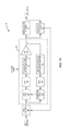
- FIGS. 5A through 13 illustrate embodiments of a transmitter 28 that compensates for a non-linear characteristic of a non-linear filter 30 at an output of the transmitter 28 according to the present disclosure.
- FIG. 5A illustrates an embodiment of the transmitter 28 that includes a digital-to-analog converter (DAC) 32 , a modulator and upconverter 34 , a power amplifier (PA) 36 , an analog predistorter 38 , and the non-linear filter 30 .
- the DAC 32 receives a digital input signal and converts the digital input signal into an analog input signal.
- the modulator and upconverter 34 modulates the analog input signal according to a desired modulation scheme and upconverts the analog input signal to a desired radio frequency.
- the radio frequency (RF) signal output by the modulator and upconverter 34 is amplified to a desired output power level by the PA 36 to provide an amplified RF signal.
- the analog predistorter 38 applies a predetermined, fixed predistortion to the amplified RF signal to provide a predistorted RF signal.
- the predistortion applied by the analog predistorter 38 compensates for the non-linear characteristic of the non-linear filter 30 .
- the predistortion may be predetermined using any suitable technique.
- the predistorted signal is then filtered by the non-linear filter 30 to provide an output signal of the transmitter 28 . As a result of the predistortion, the output signal is as if the non-linear filter 30 were a linear, or substantially linear, filter.
- FIG. 5B is substantially the same as that of FIG. 5A but where the DAC 32 moved after the modulator and upconverter 34 .
- FIG. 5B illustrates that the concepts discussed herein are independent of the DAC placement. Further, while not discussed further below, it should be understood that while the placement of the DACs in the embodiments below is shown as being before modulation and upconversion, the present disclosure is not limited thereto.
- FIG. 6 illustrates an embodiment of the transmitter 28 that is similar to that of FIG. 5A .
- the transmitter 28 also includes a digital predistorter (DPD) 40 that compensates for non-linearity of the PA 36 .
- the digital predistorter 40 is adaptively configured by an adaptor 42 based on the digital input signal and a feedback signal.
- a demodulator and downconverter 44 receives a RF feedback signal that is representative of the amplified RF signal output by the PA 38 .
- the output of the demodulator and downconverter 44 is digitized by an analog-to-digital converter (ADC) 46 to provide the feedback signal to the adaptor 42 .
- ADC analog-to-digital converter
- the adaptor 42 configures the digital predistorter 40 based on a comparison of the digital input signal and the feedback signal using any suitable adaptive predistortion scheme.
- the digital predistorter 40 provides polynomial predistortion where the predistortion to compensate for the non-linearity of the PA 38 is defined by a polynomial having a number of configurable coefficients.
- the adaptor 42 adaptively configures the coefficients for the polynomial to provide the appropriate predistortion using known techniques.
- FIGS. 7 through 9 illustrate embodiments of the transmitter 28 where predistortion to compensate for the non-linear characteristic of the non-linear filter 30 is performed in the digital, rather than analog, domain.
- FIG. 7 illustrates an embodiment of the transmitter 28 that includes a digital predistorter (DPD) 48 that compensates for the non-linear characteristic of the non-linear filter 30 , a digital predistorter (DPD) 50 that compensates for the non-linearity of the PA 36 , the DAC 32 , the modulator and upconverter 34 , the PA 36 , and the non-linear filter 30 connected as shown.
- DPD digital predistorter
- DPD digital predistorter
- the digital predistorter 48 applies a predistortion to a digital input signal to provide a first predistorted signal that has been predistorted to compensate for the non-linear characteristic of the non-linear filter 30 .
- the digital predistorter 50 then applies a predistortion to the first predistorted signal to provide a second predistorted signal that has also been predistorted to compensate for the non-linearity of the PA 36 .
- both the predistortion applied by the digital predistorter 48 and the predistortion applied by the digital predistorter 50 are predetermined and fixed.
- the DAC 32 then converts the second predistorted signal to an analog signal.
- the analog signal from the DAC 32 is then modulated and amplified by the modulator and upconverter 34 .
- the PA 36 then amplifies the RF signal output from the modulator and upconverter 34 to provide an amplified RF signal that is then filtered by the non-linear filter 30 . Due to the predistortion applied by the digital predistorter 48 , the output signal from the non-linear filter 30 is as if the non-linear filter 30 was a linear, or substantially linear, filter. Note that the digital predistorter 50 , the DAC 32 , the modulator and upconverter 34 , and the PA 36 operate together as a linear part 52 , or linear sub-system.
- FIG. 8 illustrates an embodiment of the transmitter 28 where the digital predistorters 48 and 50 ( FIG. 7 ) have been combined into a single digital predistorter (DPD) 54 .
- the digital predistorter 54 applies a predetermined and fixed predistortion that compensates for both the non-linearity of the PA 36 and the non-linear characteristic of the non-linear filter 30 .
- FIG. 9 illustrates an embodiment of the transmitter 28 that is similar to that of FIG. 7 .
- the transmitter 28 also includes a digital predistorter (DPD) 56 that compensates for non-linearity of the PA 36 .
- the digital predistorter 56 is adaptively configured by an adaptor 58 based on the first predistorted signal from the digital predistorter 48 and a feedback signal.
- a demodulator and downconverter 60 receives a RF feedback signal that is representative of the amplified radio frequency output signal output by the PA 36 .
- the output of the demodulator and downconverter 60 is digitized by an analog-to-digital converter (ADC) 62 to provide the feedback signal to the adaptor 58 .
- ADC analog-to-digital converter
- the adaptor 58 configures the digital predistorter 56 based on a comparison of the first predistorted signal from the digital predistorter 48 and the feedback signal using any suitable adaptive predistortion scheme.
- the digital predistorter 56 provides polynomial predistortion where the predistortion to compensate for the non-linearity of the PA 36 is defined by a polynomial having a number of configurable coefficients.
- the adaptor 58 adaptively configures the coefficients for the polynomial to provide the appropriate predistortion using known techniques.
- FIGS. 10 through 13 illustrate embodiments of the transmitter 28 providing adaptive predistortion to compensate for the non-linear characteristic of the non-linear filter 30 .
- FIG. 10 illustrates an embodiment of the transmitter 28 that is similar to that of FIG. 7 .
- the transmitter 28 includes a digital predistorter (DPD) 64 that compensates for non-linearity of the non-linear filter 30 , where the digital predistorter 64 is adaptively configured by an adaptor 66 based on the digital input signal and a feedback signal.
- a demodulator and downconverter 68 receives a RF feedback signal that is representative of the output signal output by the non-linear filter 30 .
- the output of the demodulator and downconverter 68 is digitized by an analog-to-digital converter (ADC) 70 to provide the feedback signal to the adaptor 66 .
- ADC analog-to-digital converter
- the adaptor 66 configures the digital predistorter 64 based on the digital input signal and the feedback signal using any suitable adaptive predistortion scheme. For instance, in one embodiment, the digital predistorter 64 provides polynomial predistortion where the predistortion to compensate for the non-linear characteristic of the non-linear filter 30 is defined by a polynomial having a number of configurable coefficients. The adaptor 66 adaptively configures the coefficients for the polynomial to provide the appropriate predistortion.
- FIG. 11 illustrates an embodiment of the transmitter 28 that is similar to that of FIG. 10 .
- the transmitter 28 also includes adaptive predistortion for the PA 36 in the manner described above with respect to FIG. 9 .
- FIGS. 12 and 13 are similar to FIGS. 10 and 11 , respectively.
- the digital predistorter 64 is configured by an adaptor 72 based on a reference signal that corresponds to the input signal of the non-linear filter 30 and a feedback signal that corresponds to the output signal of the non-linear filter 30 .
- FIG. 14 graphically illustrates operating regions for the non-linear filter 30 with and without predistortion according to one exemplary embodiment.
- point “A” is a defined boundary point below which the non-linear filter 30 is treated as linear.
- the non-linear filter 30 must operate within operating region 74 where P IN is average input power and P IN-A is peak input power.
- the peak input power must be less than or equal to the input power level defined by point A.
- the non-linear filter 30 is enabled to operate within operating region 76 .
- the non-linear filter 30 is linearized below a point “B”.
- the average input power is P IN-PD and the peak input power is P IN-B , where P IN-PD is much greater than P IN and P IN-B is substantially greater than P IN-A .
- the benefits of predistorting compensate for the non-linear characteristic of the non-linear filter 30 including, for example, taking greater advantage of the power handling capabilities of the non-linear filter 30 .
- linearity can be maintained over a much larger power range for a particular type of filter.
- a ceramic or monoblock filter can be used for low power base stations that operate in higher power level, for example higher than 5 W, thereby avoiding the need for bulky cavity type filters.
- the manufacturing yield for cavity type filters can jump right away from current 60% to nearly 100% in the first round of cavity filter manufacturing, because the non-linearity specification is no longer a requirement for the cavity filter production.
- the costly filter non-linearity-fixing process for the cavity filters failed in the first round can be eliminated; as a result, the average cavity filter manufacturing cost can get a great reduction.
- conventional miniature filters may be used for user equipment devices in next generation and future generation cellular communication networks, which require or will likely require greater dynamic power range.
- the adaptor 72 operates to adaptively configure the digital predistorter 64 to compensate for, or counteract, the non-linear characteristic of the non-linear filter 30 .
- the digital predistorter 64 has both the undesired and unknown non-linear characteristic and a desired and known linear characteristic.
- the adaptor 72 is to operate such that the digital predistorter 64 compensates for only the non-linear characteristic of the non-linear filter 30 .
- the non-linear filter 30 is a physical device that does not include a reference point for only the non-linear characteristic. Specifically, the output of the non-linear filter 30 cannot be used as a reference point for the non-linear characteristic of the non-linear filter 30 because the output of the non-linear filter 30 represents both the non-linear characteristic and the linear characteristic of the non-linear filter 30 .
- FIG. 15 illustrates a model 78 for the non-linear filter 30 that can be utilized to provide a reference point for adaptive configuration of the digital predistorter 64 for predistortion of the non-linear characteristic of the non-linear filter 30 according to one embodiment of the present disclosure. While the following discussion focuses on the use of the model 78 for adaptation of the digital predistorter 64 to compensate for the non-linear characteristic of the non-linear filter 30 , the model 78 is not limited thereto.
- the model 78 may be used to model any non-linear system, and particularly any non-linear physical device, having an undesired non-linear characteristic and a desired linear characteristic. Further, the model 78 may then be used for adaptive predistortion to compensate for the non-linear characteristic of the non-linear system.
- the model 78 for the non-linear filter 30 is a concatenation of a non-linear filter model 80 , which also referred to herein as model A, and a linear filter model 82 , which is also referred to herein as model B.
- the non-linear filter model 80 is a model of the undesired and unknown non-linear characteristic of the non-linear filter 30 .
- the non-linear characteristic of the non-linear filter 30 may vary over time and/or may vary from one device to another.
- the linear filter model 82 is a model of the desired and known linear characteristic of the non-linear filter 30 . In other words, the linear filter model 82 is a model of the known linear characteristic of the non-linear filter 30 when operating in its linear region.
- the linear characteristic does not vary over time and is known either by design or by measurement on a per device basis to take device variations into consideration.
- the concatenation of the non-linear filter model 80 and the linear filter model 82 represent the actual response of the non-linear filter 30 particularly when operating in its non-linear region.
- the non-linear filter model 80 may model the non-linear characteristic of the non-linear filter 30 using a variable tapped delay line followed by a weighting and summation with a number of coefficients (determined via adaptation).
- the non-linear filter model 80 is a memory-less non-linear function. In this case, the output of the non-linear filter model 80 only depends on the current input of the non-linear filter model 80 and not any of its previous inputs.
- the non-linear filter 30 is modeled as a concatenation of the non-linear filter model 80 followed by the linear filter model 82 , the non-linear filter 30 is physically a single device. As such, there is no physical reference point obtainable from the non-linear filter 30 that is equivalent to the reference point at the output of the non-linear filter model 80 .
- the model 78 provides the needed reference point for adaptive predistortion to compensate for the non-linear characteristic and not the linear characteristic of the non-linear filter 30 .
- FIG. 16 illustrates one embodiment of the adaptor 72 that utilizes the model 78 of FIG. 15 to adaptively configure the digital predistorter 64 to compensate for the non-linear characteristic of the non-linear filter 30 according to one embodiment of the present disclosure.
- the adaptor 72 may be implemented as any suitable type of circuitry such as, for example, one or more Application Specific Integrated Circuits (ASICs) or one or more microprocessors.
- ASICs Application Specific Integrated Circuits
- the adaptor 72 includes a first loop, which is referred to herein as a non-linear filter model identification loop, and a second loop, which is referred to herein as a predistorter model identification loop.
- the non-linear filter model identification loop includes the model 78 , which as discussed above is a concatenation of the non-linear filter model 80 followed by the linear filter model 82 , and a subtraction function 84 .
- the non-linear filter model identification loop operates to provide a reference signal at reference point 86 .
- the reference signal at the reference point 86 is referred to herein as a reference signal for the non-linear characteristic of the non-linear filter 30 .
- the reference signal for the non-linear characteristic of the non-linear filter 30 is not directly obtainable from the non-linear filter 30 since the non-linear filter 30 is a single physical device.
- the predistorter model identification loop includes the non-linear filter model 80 , an inverse model 88 , and a subtraction function 90 .
- the inverse model 88 is an inverse model of the non-linear filter model 80 .
- the predistorter model identification loop obtains the parameters, which in this embodiment are coefficients (C PD ), for configuring the digital predistorter 64 .
- the coefficients (C PD ) provided to the digital predistorter 64 are the same coefficients determined for the inverse model 88 via the predistorter model identification loop.
- the adaptor 72 first trains the non-linear filter model 80 using the non-linear filter model identification loop. During this training, parameters, which in this embodiment are coefficients, for the non-linear filter model 80 are determined. Once the non-linear filter model 80 is trained, the predistorter model identification loop trains the inverse model 88 . More specifically, an output signal from the linear part 52 of the transmitter 28 is provided as an input signal to the adaptor 72 . Once the non-linear filter model 80 is trained, the adaptor 72 provides the input signal of the adaptor 72 to the non-linear filter model 80 , and the non-linear filter model 80 outputs, at the reference point 86 , the reference signal for the non-linear characteristic of the non-linear filter 30 .
- the adaptor 72 then provides the reference signal for the non-linear characteristic of the non-linear filter 30 to the inverse model 88 , which then provides a corresponding output signal.
- the subtraction function 90 compares the output of the inverse model 88 and the input signal to the adaptor 72 to provide an error signal.
- the error signal represents a difference between the output of the inverse model 88 and the input signal of the adaptor 72 .
- the adaptor 72 updates the coefficients for the inverse model 88 based on the error signal until the error signal is minimized (e.g., until the error signal is zero or approximately zero).
- the adaptor 72 provides the coefficients for the inverse model 88 to the digital predistorter 64 as the coefficients (C PD ) for the digital predistorter 64 .
- This process continues such that the adaptor 72 continues to update the coefficients for the non-linear filter model 80 , the inverse model 88 , and the digital predistorter 64 in response to variations in the non-linear characteristic of the non-linear filter 30 .
- the adaptor 72 of FIG. 16 is shown as being used to adaptively configure the digital predistorter 64 to compensate for the non-linear characteristic of the non-linear filter 30 in the transmitter 28 , the adaptor 72 is not limited thereto.
- the adaptor 72 of FIG. 16 may be used to adaptively configure a predistorter to compensate for a non-linear characteristic of any type of non-linear system or non-linear device that has both an undesired non-linear characteristic and a desired linear characteristic.
- FIG. 17 through 21 describe systems and methods for training the non-linear filter model 80 . Note, however, that the systems and methods of FIGS. 17 through 21 are exemplary. Other techniques may be used to train the non-linear filter model 80 . However, FIGS. 17 through 21 describe one scheme that enables conventional adaptive filtering techniques to be used to train the non-linear filter model 80 .
- FIG. 17 is a more detailed illustration of the non-linear filter model 80 according to one embodiment of the present disclosure.
- the non-linear filter model 80 includes a number (P A ) of memory basis functions 92 and a weight and sum function 94 .
- the number P A is equal to the number of coefficients for the non-linear filter model 80 .
- the memory basis functions 92 receive the input signal of the non-linear filter model 80 , which is denoted x A,IN (n), and output corresponding memory basis function output signals x A,BF _ M _ 1 (n) through x A,BF _ M _ P A (n).
- the weight and sum function 94 applies coefficients (C A ) for the non-linear filter model 80 as weightings to the corresponding memory basis function output signals x A,BF _ M _ 1 (n) through x A,BF _ M _ P A (n) and then sums the weighted basis function output signals to provide the output signal of the non-linear filter model 80 , which is denoted as x A, OUT (n).
- FIG. 18 is a more detailed illustration of the memory basis functions 92 of FIG. 17 according to one embodiment of the present disclosure.
- the memory basis functions 92 include a number (K A ) of memory-less basis functions 96 and a number (K A ) of memory structures 98 - 1 through 98 -K A .
- the memory-less basis functions 96 receive the input signal of the non-linear filter model 80 , which is denoted x A, IN (n), and output corresponding memory-less basis function output signals x A,BF _ ML _ 1 (n) through x A,BF _ ML _ K A (n).
- the memory structures 98 - 1 through 98 -K A receive the memory-less basis function output signals x A,BF _ ML _ 1 (n) through x A,BF _ ML _ P A (n) and output the memory basis function output signals x A,BF M 1 (n) through x A,BF M (K A Q A ) (n).
- FIG. 19 illustrates the memory-less basis functions 96 of FIG. 18 in more detail according to one embodiment of the present disclosure.
- the memory-less basis functions 96 includes a number (K A ) of memory-less basis functions 100 - 1 through 100 -K A .
- FIG. 20 illustrates an integrated model 102 that is equivalent to the model 78 but where stages have been rearranged such that the application of the coefficients (C A ) is at a final stage of the integrated model 102 . More specifically, in the model 78 , the weight and sum function 94 and the linear filter model 82 are both linear.
- the sequence of the weight and sum function 94 and the linear filter 82 can be reversed as is done in the integrated model 102 .
- the memory basis function output signals x A,BF _ M _ 1 (n) through x A,BF _ M _ P A (n) are passed through corresponding linear filter models 104 - 1 through 104 -P A to provide corresponding basis function output signals x A,BF _ IM _ 1 (n) through X A,BF _ IM _ P A (n).
- the linear filter models 104 - 1 through 104 -P A are equivalent to the linear filter model 82 , which has known coefficients (C B ).
- the memory basis functions 92 and the linear filter models 104 - 1 through 104 -P A become basis functions for the integrated model 102 .
- the weight and sum function 94 then applies the coefficients (C A ) as weightings to the corresponding basis function output signals x A,BF _ IM _ 1 (n) through X A,BF _ IM _ P A (n) and then sums the weighted basis function output signals to provide the output signal x OUT (n) of the integrated model 102 , which is equivalent to the output signal x OUT (n) of the model 78 .
- the coefficients (C A ) for the non-linear filter model 80 can be determined using adaptive filtering.
- T denotes transpose.
- a known adaptive filtering algorithm can then be used to solve the following equation for the coefficients (C A ) for the non-linear filter model 80 :
- C A is a vector of the coefficients for the non-linear filter model 80 defined as:
- C A [c A _ 1 , c A _ 2 , . . . , c A _ P A ] T , where c A _ 1 , c A _ 2 , . . . , C A _ P A are the coefficients for the non-linear filter model 80 .
- FIG. 21 illustrates an embodiment of the adaptor 72 that utilizes the integrated model 102 of FIG. 20 to train the non-linear filter model 80 to adaptively configure the digital predistorter 64 to compensate for the non-linear characteristic of the non-linear filter 30 according to one embodiment of the present disclosure.
- This embodiment of the adaptor 72 is similar to that of FIG. 16 , but where the integrated model 102 is utilized for training the non-linear filter model 80 .
- the adaptor 72 includes a first loop, which is referred to herein as a non-linear filter model identification loop, and a second loop, which is referred to herein as a predistorter model identification loop.
- the non-linear filter model identification loop includes the integrated model 102 and a subtraction function 106 and is utilized by the adaptor 72 to train the non-linear filter model 80 . More specifically, the output of the linear part 52 of the transmitter 28 (or the input of the non-linear filter 30 ), is received as the input signal of the adaptor 72 . The adaptor 72 passes the input signal through the integrated model 102 to provide the output signal of the integrated model 102 . The subtraction function 106 compares the output signal of the integrated model 102 and a feedback signal that represents the output signal of the non-linear filter 30 to provide an error signal that represents a difference between the output signal of the integrated model 102 and the feedback signal.
- the adaptor 72 trains the coefficients (C A ) for the integrated model 102 until the error signal has been minimized (e.g., reduced to zero or approximately zero). This process continues such that the coefficients (C A ) are updated in response to variations in the non-linear characteristic of the non-linear filter 30 .
- the predistorter model identification loop includes the non-linear filter model 80 , the inverse model 88 , and the subtraction function 90 , as described above with respect to FIG. 16 .
- the inverse model 88 is an inverse model of the non-linear filter model 80 .
- the coefficients (C A ) determined for the non-linear filter model 80 using the integrated model 102 are utilized in the predistorter model identification loop to train the inverse model 88 .
- the adaptor 72 passes the input signal of the adaptor 72 through the non-linear filter model 80 (which is configured with the coefficients (C A ) determined using the integrated model 102 ) to provide the reference signal for the non-linear characteristic of the non-linear filter 30 at the reference point 86 .
- the adaptor 72 then provides the reference signal for the non-linear characteristic of the non-linear filter 30 to the inverse model 88 , which then provides a corresponding output signal.
- the subtraction function 90 compares the output of the inverse model 88 and the input signal to the adaptor 72 to provide an error signal.
- the error signal represents a difference between the output of the inverse model 88 and the input signal of the adaptor 72 .
- the adaptor 72 updates the coefficients for the inverse model based on the error signal until the error signal is minimized (e.g., until the error signal is zero or approximately zero). At that point, the inverse model 88 is trained, and the adaptor 72 provides the coefficients for the inverse model 88 to the digital predistorter 64 as the coefficients (C PD ) for the digital predistorter 64 . This process continues such that the adaptor 72 continues to update the coefficients for the non-linear filter model 80 , the inverse model 88 , and the digital predistorter 64 in response to variations in the non-linear characteristic of the non-linear filter 30 .
- the adaptor 72 of FIG. 21 is shown as being used to adaptively configure the digital predistorter 64 to compensate for the non-linear characteristic of the non-linear filter 30 in the transmitter 28 , the adaptor 72 is not limited thereto.
- the adaptor 72 of FIG. 21 may be used to adaptively configure a predistorter to compensate for a non-linear characteristic of any type of non-linear system or non-linear device that has both an undesired non-linear characteristic and a desired linear characteristic.
- FIG. 22 illustrates a system 108 that utilizes the integrated model 102 to train a non-linear characteristic of a non-linear subsystem 110 according to one embodiment of the present disclosure.
- the non-linear subsystem 110 is generally any type of non-linear subsystem that includes an undesired non-linear characteristic and a desired linear characteristic.
- an adaptive filtering technique is used in order to train a non-linear model for the non-linear characteristic of the non-linear subsystem 110 in the manner described above.
- an input signal, x IN (n) is provided to the non-linear subsystem 110 and the integrated model 102 .
- a subtraction function 112 compares an output signal, x′ OUT (n), of the non-linear subsystem 110 and an output signal, x OUT (n), of the integrated model 102 to provide an error signal to the integrated model 102 that represents a difference between the two output signals x OUT (n) and x′ OUT (n). Based on the error signal, coefficients for the integrated model 102 , which are also the coefficients for the non-linear model of the non-linear characteristic of the non-linear subsystem 110 , are updated to minimize the error signal (e.g., updated to make the error signal zero or approximately zero).
- the coefficients determined for the non-linear model of the non-linear characteristic of the non-linear subsystem 110 may then be used to, for example, predistort the input signal to compensate for the non-linear characteristic of the non-linear subsystem 110 in the manner described above.
- FIG. 23 illustrates another embodiment transmitter 28 including the adaptor 72 that provides bandwidth reduction for the adaptor 72 according to one embodiment of the present disclosure. Specifically, this embodiment reduces a bandwidth that the adaptor 72 processes as compared to a bandwidth of the output signal of the non-linear filter 30 , which may be at or above the limit of the processing speed of current state-of-the-art ASICs or microprocessors without employing techniques specifically for handling higher than clock rate signal processing. Reducing the bandwidth being processed by the adaptor 72 limits the complexity and thus the cost of implementing the adaptor 72 .
- Reducing the bandwidth also enables linearization for non-linear systems of wider bandwidths or, in other words, increases a maximum bandwidth for which linearization can be performed beyond a maximum bandwidth that can be handled by the hardware (e.g., ASIC or microprocessor) in which the adaptor 72 is implemented.
- This embodiment of the adaptor 72 is similar to that of FIG. 16 .
- the non-linear filter model 80 is, or can be approximated as, a memory-less non-linear function. This means that the output of the non-linear filter model 80 depends only on the current input (or approximately so), and does not give significant contribution to the current output of the non-linear filter model 80 . Any dependency of the output of the non-linear filter model 80 on previous inputs can be ignored. Because the non-linear filter model 80 is or can be approximately a memory-less non-linear function, the non-linear characteristic of the non-linear filter 30 is frequency independent or can be approximately assumed to be frequency independent. This can be assumed true as long as the frequency dependency of the non-linear characteristic can be modeled by a concatenation of a frequency independent non-linear filter model 80 followed by the linear filter model 82 , which can be frequency dependent.
- the transmitter 28 includes a narrowband filter 114 that receives a feedback signal that is representative of the output signal of the non-linear filter 30 and outputs a filtered feedback signal having a significantly reduced bandwidth.
- the bandwidth of the narrowband filter 114 is arbitrarily small.
- the bandwidth of the narrowband filter 114 is substantially smaller than the bandwidth of the output signal of the non-linear filter 30 , but the actual bandwidth of the narrowband filter 114 may be a tradeoff between performance and cost/complexity.
- the adaptor 72 includes a first loop, which is referred to herein as a non-linear filter model identification loop, and a second loop, which is referred to herein as a predistorter model identification loop.
- the non-linear filter model identification loop includes a model 116 of a subsystem formed by the non-linear filter 30 and the narrowband filter 114 and the subtraction function 84 .
- the model 116 includes the model 78 of the non-linear filter 30 , which includes the non-linear filter model 80 and the linear filter model 82 , and a narrowband filter model 118 .
- the narrowband filter model 118 is a model of the narrowband filter 114 , which is known.
- the narrowband filter 114 may be implemented in the analog or digital domain, and, likewise, the narrowband filter model 118 is implemented in the digital domain.
- the narrowband filter model 118 may be known from design or from measurements on a per device basis.
- the linear filter model 82 and the narrowband filter model 118 are both linear and, as such, can be combined into or treated as a single linear model. From this point, the adaptor 72 operates in the same manner as described above with respect to FIG. 16 .
- the integrated model 102 FIG. 21
- FIGS. 24A through 24D are frequency domain illustrations of exemplary signals at reference points A through C in FIG. 23 .
- FIG. 24A illustrates the input signal to the non-linear filter 30 at reference point A in FIG. 23 .
- the input signal has a wide bandwidth.
- FIG. 24B illustrates the output signal at the output of the non-linear filter 30 at reference point B in FIG. 23 .
- the output signal includes undesired distortions, including distortions in the passband of the non-linear filter 30 .
- FIG. 24C illustrates a frequency response of the narrowband filter 114 of FIG. 23 .
- the bandwidth (BW 1 ) of the narrowband filter 114 is substantially smaller than the bandwidth of the output signal of the non-linear filter 30 .
- FIG. 24A illustrates the input signal to the non-linear filter 30 at reference point A in FIG. 23 .
- the input signal has a wide bandwidth.
- FIG. 24B illustrates the output signal at the output of the non-linear filter 30
- 24D illustrates the filtered feedback signal (i.e., filtered output signal of the non-linear filter 30 ) at reference point C of FIG. 23 .
- the bandwidth of the filtered feedback signal is equal to the bandwidth (BW 1 ) of the narrowband filter 114 .
- the adaptor 72 of FIG. 23 is shown as being used to adaptively configure the digital predistorter 64 to compensate for the non-linear characteristic of the non-linear filter 30 in the transmitter 28 , the adaptor 72 is not limited thereto. As shown in FIG. 25 , the adaptor 72 in combination with the digital predistorter 64 and the narrowband filter 114 can be used to provide adaptive predistortion to compensate for a non-linear characteristic of any type of non-linear subsystem 122 (e.g., a non-linear power amplifier).
- any type of non-linear subsystem 122 e.g., a non-linear power amplifier
Landscapes
- Engineering & Computer Science (AREA)
- Power Engineering (AREA)
- Physics & Mathematics (AREA)
- Nonlinear Science (AREA)
- General Physics & Mathematics (AREA)
- Algebra (AREA)
- Signal Processing (AREA)
- Mathematical Analysis (AREA)
- Mathematical Optimization (AREA)
- Pure & Applied Mathematics (AREA)
- Computer Networks & Wireless Communication (AREA)
- Microelectronics & Electronic Packaging (AREA)
- Amplifiers (AREA)
- Transmitters (AREA)
Priority Applications (4)
| Application Number | Priority Date | Filing Date | Title |
|---|---|---|---|
| US13/333,422 US9819318B2 (en) | 2011-12-21 | 2011-12-21 | Architecture of a low bandwidth predistortion system for non-linear RF components |
| CN201280070302.5A CN104115408B (zh) | 2011-12-21 | 2012-12-20 | 用于非线性rf组件的低带宽预失真子系统的体系结构 |
| EP12829216.6A EP2795802B1 (de) | 2011-12-21 | 2012-12-20 | Architektur eines schmalbandigen vorverzerrungssystems für nichtlineare hf-komponenten |
| PCT/IB2012/057569 WO2013093862A2 (en) | 2011-12-21 | 2012-12-20 | Architecture of a low bandwidth predistortion system for non-linear rf components |
Applications Claiming Priority (1)
| Application Number | Priority Date | Filing Date | Title |
|---|---|---|---|
| US13/333,422 US9819318B2 (en) | 2011-12-21 | 2011-12-21 | Architecture of a low bandwidth predistortion system for non-linear RF components |
Publications (2)
| Publication Number | Publication Date |
|---|---|
| US20130163694A1 US20130163694A1 (en) | 2013-06-27 |
| US9819318B2 true US9819318B2 (en) | 2017-11-14 |
Family
ID=47833307
Family Applications (1)
| Application Number | Title | Priority Date | Filing Date |
|---|---|---|---|
| US13/333,422 Active 2035-04-04 US9819318B2 (en) | 2011-12-21 | 2011-12-21 | Architecture of a low bandwidth predistortion system for non-linear RF components |
Country Status (4)
| Country | Link |
|---|---|
| US (1) | US9819318B2 (de) |
| EP (1) | EP2795802B1 (de) |
| CN (1) | CN104115408B (de) |
| WO (1) | WO2013093862A2 (de) |
Families Citing this family (4)
| Publication number | Priority date | Publication date | Assignee | Title |
|---|---|---|---|---|
| US8970418B1 (en) * | 2013-08-19 | 2015-03-03 | Analog Devices, Inc. | High output power digital-to-analog converter system |
| US10056924B2 (en) | 2013-08-19 | 2018-08-21 | Analog Devices, Inc. | High output power digital-to-analog converter system |
| EP3197113B1 (de) * | 2014-11-14 | 2020-06-03 | Huawei Technologies Co. Ltd. | Kernmodul eines analogen vorverzerrers und system eines analogen vorverzerrers |
| CN114268334B (zh) * | 2021-12-31 | 2023-09-19 | 展讯通信(上海)有限公司 | 一种信号处理方法、装置、芯片、电子设备和存储介质 |
Citations (20)
| Publication number | Priority date | Publication date | Assignee | Title |
|---|---|---|---|---|
| US5923712A (en) | 1997-05-05 | 1999-07-13 | Glenayre Electronics, Inc. | Method and apparatus for linear transmission by direct inverse modeling |
| WO2000070750A1 (en) | 1999-05-14 | 2000-11-23 | Harris Corporation | Broadcast transmission system with single correction filter for correcting linear and non-linear distortion |
| US6320463B1 (en) | 1999-06-15 | 2001-11-20 | Alcatel | Adaptive digital pre-correction of nonlinearities introduced by power amplifiers |
| US6600516B1 (en) | 2000-04-21 | 2003-07-29 | Harris Corporation | Digital RF transmitter system employing both digital pre-correction and analog pre-correction |
| EP1335489A1 (de) | 2000-09-19 | 2003-08-13 | Japan Science and Technology Corporation | Leistungsverstärker mit kompensation nichtlinearer verzerrungen |
| US20030179831A1 (en) * | 2002-03-21 | 2003-09-25 | Deepnarayan Gupta | Power amplifier linearization |
| EP1517500A1 (de) | 2003-09-16 | 2005-03-23 | Andrew AG | Kompensation von Filtern in Funksendern |
| US20050111575A1 (en) | 2003-11-24 | 2005-05-26 | Wiseband Communications Ltd. | Amplifier linearization using non-linear predistortion |
| US20050163268A1 (en) | 2004-01-27 | 2005-07-28 | Crestcom, Inc. | Predistortion circuit and method for compensating nonlinear distortion in a digital RF communications transmitter |
| US6947711B1 (en) | 1999-11-24 | 2005-09-20 | Telefonaktiebolaget L M Ericsson (Publ) | Method and apparatus for generating a radio frequency signal |
| US20050253745A1 (en) | 2004-05-11 | 2005-11-17 | Samsung Electronics Co., Ltd. | Digital predistortion apparatus and method for a wideband power amplifier |
| US20070082617A1 (en) | 2005-10-11 | 2007-04-12 | Crestcom, Inc. | Transceiver with isolation-filter compensation and method therefor |
| US20070087704A1 (en) | 2003-10-20 | 2007-04-19 | Thomson Licensing S.A. | Predistorter for use in a wireless transmitter |
| US7469491B2 (en) | 2004-01-27 | 2008-12-30 | Crestcom, Inc. | Transmitter predistortion circuit and method therefor |
| EP2161841A1 (de) | 2008-09-08 | 2010-03-10 | Alcatel, Lucent | Vorverzerrung eines Hochfrequenzsignals |
| EP2175555A1 (de) | 2007-07-31 | 2010-04-14 | Fujitsu Limited | Verzerrungskompensationsvorrichtung und verfahren |
| US20100329387A1 (en) | 2009-06-26 | 2010-12-30 | Fujitsu Limited | Wireless communication apparatus and wireless communication method |
| US20110095820A1 (en) | 2009-10-23 | 2011-04-28 | Ralink Technology Corporation | Method for pre-distorting a power amplifier and the circuit thereof |
| WO2013044238A1 (en) | 2011-09-22 | 2013-03-28 | Dali Systems Co. Ltd. | System and method for increasing bandwidth for digital predistortion in multi-channel wideband communication systems |
| US20130243117A1 (en) | 2012-03-13 | 2013-09-19 | Samsung Electronics Co., Ltd. | Apparatus and method for a flexible digital predistortion architecture for coarse-to-fine compensation |
Family Cites Families (5)
| Publication number | Priority date | Publication date | Assignee | Title |
|---|---|---|---|---|
| US5900778A (en) * | 1997-05-08 | 1999-05-04 | Stonick; John T. | Adaptive parametric signal predistorter for compensation of time varying linear and nonlinear amplifier distortion |
| US7113551B2 (en) * | 2002-07-25 | 2006-09-26 | Intersil Corporation | Transmitter with limited spectral regrowth and method therefor |
| CN100563225C (zh) * | 2005-05-27 | 2009-11-25 | 华为技术有限公司 | 对基带数字信号进行预失真处理的通用装置 |
| JP5157479B2 (ja) * | 2008-01-28 | 2013-03-06 | 富士通株式会社 | 歪補償装置及びこれを備えた電力増幅装置 |
| JP2010232714A (ja) * | 2009-03-25 | 2010-10-14 | Advantest Corp | 信号処理装置、デジタルフィルタ、および、プログラム |
-
2011
- 2011-12-21 US US13/333,422 patent/US9819318B2/en active Active
-
2012
- 2012-12-20 WO PCT/IB2012/057569 patent/WO2013093862A2/en active Application Filing
- 2012-12-20 CN CN201280070302.5A patent/CN104115408B/zh active Active
- 2012-12-20 EP EP12829216.6A patent/EP2795802B1/de active Active
Patent Citations (23)
| Publication number | Priority date | Publication date | Assignee | Title |
|---|---|---|---|---|
| US6141390A (en) | 1997-05-05 | 2000-10-31 | Glenayre Electronics, Inc. | Predistortion in a linear transmitter using orthogonal kernels |
| US5923712A (en) | 1997-05-05 | 1999-07-13 | Glenayre Electronics, Inc. | Method and apparatus for linear transmission by direct inverse modeling |
| WO2000070750A1 (en) | 1999-05-14 | 2000-11-23 | Harris Corporation | Broadcast transmission system with single correction filter for correcting linear and non-linear distortion |
| US6320463B1 (en) | 1999-06-15 | 2001-11-20 | Alcatel | Adaptive digital pre-correction of nonlinearities introduced by power amplifiers |
| US6947711B1 (en) | 1999-11-24 | 2005-09-20 | Telefonaktiebolaget L M Ericsson (Publ) | Method and apparatus for generating a radio frequency signal |
| US6600516B1 (en) | 2000-04-21 | 2003-07-29 | Harris Corporation | Digital RF transmitter system employing both digital pre-correction and analog pre-correction |
| EP1335489A1 (de) | 2000-09-19 | 2003-08-13 | Japan Science and Technology Corporation | Leistungsverstärker mit kompensation nichtlinearer verzerrungen |
| US20030179831A1 (en) * | 2002-03-21 | 2003-09-25 | Deepnarayan Gupta | Power amplifier linearization |
| EP1517500A1 (de) | 2003-09-16 | 2005-03-23 | Andrew AG | Kompensation von Filtern in Funksendern |
| US20070087704A1 (en) | 2003-10-20 | 2007-04-19 | Thomson Licensing S.A. | Predistorter for use in a wireless transmitter |
| US7330517B2 (en) | 2003-11-24 | 2008-02-12 | P-Wave Ltd. | Amplifier linearization using non-linear predistortion |
| US20050111575A1 (en) | 2003-11-24 | 2005-05-26 | Wiseband Communications Ltd. | Amplifier linearization using non-linear predistortion |
| US20050163268A1 (en) | 2004-01-27 | 2005-07-28 | Crestcom, Inc. | Predistortion circuit and method for compensating nonlinear distortion in a digital RF communications transmitter |
| US7469491B2 (en) | 2004-01-27 | 2008-12-30 | Crestcom, Inc. | Transmitter predistortion circuit and method therefor |
| US20050253745A1 (en) | 2004-05-11 | 2005-11-17 | Samsung Electronics Co., Ltd. | Digital predistortion apparatus and method for a wideband power amplifier |
| US20070082617A1 (en) | 2005-10-11 | 2007-04-12 | Crestcom, Inc. | Transceiver with isolation-filter compensation and method therefor |
| EP2175555A1 (de) | 2007-07-31 | 2010-04-14 | Fujitsu Limited | Verzerrungskompensationsvorrichtung und verfahren |
| EP2161841A1 (de) | 2008-09-08 | 2010-03-10 | Alcatel, Lucent | Vorverzerrung eines Hochfrequenzsignals |
| US20100329387A1 (en) | 2009-06-26 | 2010-12-30 | Fujitsu Limited | Wireless communication apparatus and wireless communication method |
| US20110095820A1 (en) | 2009-10-23 | 2011-04-28 | Ralink Technology Corporation | Method for pre-distorting a power amplifier and the circuit thereof |
| WO2013044238A1 (en) | 2011-09-22 | 2013-03-28 | Dali Systems Co. Ltd. | System and method for increasing bandwidth for digital predistortion in multi-channel wideband communication systems |
| US20130077713A1 (en) * | 2011-09-22 | 2013-03-28 | Dali Systems Co., Ltd. | System and method for increasing bandwidth for digital predistortion in multi-channel wideband communication systems |
| US20130243117A1 (en) | 2012-03-13 | 2013-09-19 | Samsung Electronics Co., Ltd. | Apparatus and method for a flexible digital predistortion architecture for coarse-to-fine compensation |
Non-Patent Citations (39)
| Title |
|---|
| Bandler, J. W. et al., "Why space mapping works," Surrogate modelling and space mapping for engineering optimization, Lyngby, Denmark, Nov. 9-11, 2006, 41 pages. |
| Bandler, J. W. et al.,"Space mapping: the state of the art," IEEE Transactions Microwave on Theory and Techniques, vol. 52 No. 1, Jan. 2004, pp. 337-361. |
| Bandler, John W. et al, "Space Mapping: The State of the Art," IEEE Tranascations on Microwave Theory and Techniques, Jan. 2004, pp. 337-361, vol. 52, No. 1. |
| Benvenuto, N. et al. "A neural network approach to data predistortion with memory in digital radio systems," Proceedings of IEEE ICC, 1993, pp. 232-236. |
| Final Office Action for U.S. Appl. No. 13/333,391 dated Feb. 4, 2014, 12 pages. |
| Final Office Action for U.S. Appl. No. 13/333,391, dated May 4, 2015, 11 pages. |
| Ibnkahla, M. et al. "Neural networks for modeling nonlinear memoryless communication channels," IEEE Transactions on Communications, vol. 45, No. 7 Jul. 1997, pp. 768-771. |
| International Preliminary Report on Patentability for PCT/IB2012/057566, dated Jul. 3, 2014, 8 pages. |
| International Preliminary Report on Patentability for PCT/IB2012/057568, dated Jul. 3, 2014, 7 pages. |
| International Preliminary Report on Patentability for PCT/IB2012/057569, dated May 26, 2014, 9 pages. |
| International Preliminary Report on Patentability for PCT/IB2013/051754, dated Sep. 25, 2014, 5 pages. |
| International Search Report and Written Opinion for PCT/IB2012/057566, dated Apr. 24, 2013, 13 pages. |
| International Search Report and Written Opinion for PCT/IB2012/057568, dated May 13, 2013, 9 pages. |
| International Search Report and Written Opinion for PCT/IB2012/057569, dated Jun. 27, 2013, 12 pages. |
| International Search Report and Written Opinion for PCT/IB2013/051754, dated Jul. 11, 2013, 8 pages. |
| Liu, T. et al. "Dynamic Behavioral Modeling of 3G Power Amplifiers Using Real-Valued Time-Delay Neural Networks," IEEE Transactions Microwave Theory and Techniques, vol. 52, No. 3, Mar. 2004, pp. 1025-1033. |
| Luongvyinh, D. et al. "Behavioral modeling of power amplifiers using fully recurrent neural networks," IEEE MTT-S International Microwave Symposium Digest, Jun. 12-17, 2005, pp. 1979-1982. |
| Mkadem, F. et al. "Physically Inspired Neural Network Model for RF Power Amplifier Behavioral Modeling and Digital Predistortion," IEEE Transactions Microwave on Theory and Techniques, vol. 59, No. 4, Apr. 2011, pp. 913-923. |
| Naskas, N. et al. "Adaptive baseband predistorter for radio frequency power amplifiers based on a multilayer perceptron," 9th International Conference on Electronics, Circuits and Systems, vol. 3, Dec. 10, 2002, pp. 1107-1110. |
| Non-final Office Action for U.S. Appl. No. 13/333,391 dated May 6, 2014, 10 pages. |
| Non-Final Office Action for U.S. Appl. No. 13/333,391 dated Oct. 29, 2014, 11 pages. |
| Non-Final Office Action for U.S. Appl. No. 13/333,391, dated Aug. 20, 2013, 10 pages. |
| Non-Final Office Action for U.S. Appl. No. 13/333,391, dated Mar. 15, 2013, 10 pages. |
| Non-Final Office Action for U.S. Appl. No. 13/333,407, dated Jun. 4, 2013, 14 pages. |
| Non-final Office Action for U.S. Appl. No. 13/443,949 dated Jan. 3, 2014, 6 pages. |
| Notice of Allowance and Examiner-Initiated Interview Summary for U.S. Appl. No. 13/443,949 dated Apr. 14, 2014, 9 pages. |
| Notice of Allowance for U.S. Appl. No. 13/333,407, dated Oct. 7, 2013, 9 pages. |
| Olurotimi, O., "Recurrent neural network training with feedforward complexity," IEEE Transactions on Neural Networks, vol. 5, No. 2, Mar. 1994, pp. 185-197. |
| Pedro, J. et al. "A Comparative Overview of Microwave and Wireless Power-Amplifier Behavioral Modeling Approaches," IEEE Transactions Microwave on Theory and Techniques, vol. 58, No. 1, Apr. 2005, pp. 1150-1163. |
| Rawat, M. et al. "Adaptive Digital Predistortion of Wireless Power Amplifiers/Transmitters Using Dynamic Real-Valued Focused Time-Delay Line Neural Networks," IEEE Transactions Microwave Theory and Techniques, vol. 58, No. 1, Jan. 2010, pp. 95-104. |
| Tsutsumi J. et al., "Influence of linear and non-linear distortions in SAW/FBAR duplexers for 3rd generation mobile phone systems," Proceedings of the European Microwave Association, vol. 3, Jun. 2007, pp. 120-127. |
| Ueda, M. et al., "Investigation on nonlinear distortion of acoustic devices for radio-frequency applications and its suppression," 2009 IEEE International Ultrasonics Symposium, Sep. 2009, pp. 876-879. |
| Written Opinion of the International Preliminary Examining Authority for PCT/IB2012/057569, dated Mar. 27, 2014, 6 pages. |
| Zhang, L. et al., "Efficient analytical formulation and sensitivity analysis of neuro-space mapping for nonlinear microwave device modeling," IEEE Transactions Microwave on Theory and Techniques, vol. 53 No. 9, Sep. 2005, pp. 2752-2767. |
| Zhang, L. et al., "Neuro-space mapping technique for nonlinear device modeling and large signal simulation," IEEE MTT-S Internatinoal Microwave Symposium Digest, Jun. 8-13, 2003, pp. 173-176. |
| Zhang, L. et al., "Neuro-space mapping technique for semiconductor device modeling," Optimization and Engineering, vol. 9 No. 4, 2008, pp. 393-405. |
| Zhang, Q. et al., "Artificial Neural Networks for RF and Microwave Design: From Theory to Practice," IEEE Transactions on Microwave Theory and Techniques, vol. 51, No. 4, Part 2, Apr. 2003, pp. 1339-1350. |
| Zhang, Q. J., "Artifical Neural Networks for RF and Microwave design: From theory to practice," Nov. 26, 2002, 55 pages, http://www.doe.carleton.ca/˜qjz/ANN-Tutorial/Slides/ANN-Tutorial-Slides-11-26-02.pps. |
| Zhang, Q. J., "Artifical Neural Networks for RF and Microwave design: From theory to practice," Nov. 26, 2002, 55 pages, http://www.doe.carleton.ca/˜qjz/ANN—Tutorial/Slides/ANN—Tutorial—Slides—11-26-02.pps. |
Also Published As
| Publication number | Publication date |
|---|---|
| US20130163694A1 (en) | 2013-06-27 |
| WO2013093862A2 (en) | 2013-06-27 |
| EP2795802B1 (de) | 2019-10-23 |
| CN104115408A (zh) | 2014-10-22 |
| WO2013093862A3 (en) | 2013-08-15 |
| EP2795802A2 (de) | 2014-10-29 |
| CN104115408B (zh) | 2016-03-30 |
Similar Documents
| Publication | Publication Date | Title |
|---|---|---|
| US9374044B2 (en) | Architecture of nonlinear RF filter-based transmitter | |
| US8649745B2 (en) | Adaptive predistortion for a non-linear subsystem based on a model as a concatenation of a non-linear model followed by a linear model | |
| CN101175061B (zh) | 一种ofdm发射机的自适应数字预失真方法和装置 | |
| CN104885369B (zh) | 用于并发多频带传送器的低复杂性数字预失真 | |
| US8989307B2 (en) | Power amplifier system including a composite digital predistorter | |
| KR101789924B1 (ko) | 적응형 디지털 전치 왜곡을 위한 디바이스 및 방법 | |
| CN104937841A (zh) | 用于pa线性化的频带限制自适应的系统和方法 | |
| WO2003085822A1 (en) | Adaptive digital pre-distortion using amplifier model that incorporates frequency-dependent non-linearities | |
| JP6554265B2 (ja) | 基底帯域デジタル前置歪アーキテクチャ | |
| US8811532B2 (en) | Architecture and the training method of a PA DPD system with space mapping applied in the predistorter | |
| CN111064439B (zh) | 一种改善短波数字预失真性能的系统及方法 | |
| US9819318B2 (en) | Architecture of a low bandwidth predistortion system for non-linear RF components | |
| KR20120070047A (ko) | 비선형 왜곡의 보상을 위한 전치 왜곡 장치 및 방법 | |
| EP2752995B1 (de) | Modellierung eines Senders und/oder eines Sende-Beobachtungs-Empfängerfrequenzgangs und Verwendung davon | |
| Li et al. | Nonideal effects of reconstruction filter and I/Q imbalance in digital predistortion | |
| RU2731128C1 (ru) | Способ совместной цифровой линеризации усилителя мощности и квадратурного модулятора | |
| CN112511112A (zh) | 数字预失真电路及数字预失真方法 | |
| Garcia et al. | Adaptive digital correction of gain and phase imbalances in LINC transmitters |
Legal Events
| Date | Code | Title | Description |
|---|---|---|---|
| AS | Assignment |
Owner name: TELEFONAKTIEBOLAGET L M ERICSSON (PUBL), SWEDEN Free format text: ASSIGNMENT OF ASSIGNORS INTEREST;ASSIGNORS:BAI, CHUNLONG;JIAN, CHUNYUN;SICH, EDWARD;REEL/FRAME:027647/0787 Effective date: 20111221 |
|
| STCF | Information on status: patent grant |
Free format text: PATENTED CASE |
|
| MAFP | Maintenance fee payment |
Free format text: PAYMENT OF MAINTENANCE FEE, 4TH YEAR, LARGE ENTITY (ORIGINAL EVENT CODE: M1551); ENTITY STATUS OF PATENT OWNER: LARGE ENTITY Year of fee payment: 4 |