US981822A - Concrete-piling retaining-wall structure. - Google Patents
Concrete-piling retaining-wall structure. Download PDFInfo
- Publication number
- US981822A US981822A US56659110A US1910566591A US981822A US 981822 A US981822 A US 981822A US 56659110 A US56659110 A US 56659110A US 1910566591 A US1910566591 A US 1910566591A US 981822 A US981822 A US 981822A
- Authority
- US
- United States
- Prior art keywords
- concrete
- wall
- horizontal
- piles
- units
- Prior art date
- Legal status (The legal status is an assumption and is not a legal conclusion. Google has not performed a legal analysis and makes no representation as to the accuracy of the status listed.)
- Expired - Lifetime
Links
Images


Classifications
-
- E—FIXED CONSTRUCTIONS
- E02—HYDRAULIC ENGINEERING; FOUNDATIONS; SOIL SHIFTING
- E02D—FOUNDATIONS; EXCAVATIONS; EMBANKMENTS; UNDERGROUND OR UNDERWATER STRUCTURES
- E02D29/00—Independent underground or underwater structures; Retaining walls
- E02D29/02—Retaining or protecting walls
- E02D29/0258—Retaining or protecting walls characterised by constructional features
- E02D29/0266—Retaining or protecting walls characterised by constructional features made up of preformed elements
Definitions
- This invention relates to. concrete-piling bulkheads or retaining-wall structures particularly adapted for installation adjacent to or in water-courses, especially involving the use of reinforced-concrete as distinguished from timber or structural steel, particularly when such retaining-wall is subjected to great horizontal loads as of reclaimed land behind the retaining-wall or of a breakwater-fill, or to heavy vertical loads as of, traveling cranes or other corres'pondingly-heavy vertical loads on oredlocks, etc., and particularly where the structure is exposed to the alternate action of high and low water-levels, as of tides, especially during installation.
- the general object of the invention is' a strong and permanent structure of economical cost which shall be adequatefor the stated conditions of materials used, of loads imposed, and of variations of waterlevel, or any of them.
- the invention is embodied in the retaining-wall structure disclosed herein, wherein the sheet-piling wall itself iscomposed of,
- piling units of concrete but having such construction that they constitute a longitudinally-interlocked tight wall, and that they have sufiicient strength, as individuals, to
- the concrete units. of the sheet-piling wall have sufficient strength, in cooperationwith the horizontal-beam, and preferably but not necessarily the buttress-walls, ,to serve to buttress the entire structure, even in the absence. of any extra piles which may otherwise be used to assist the buttress-walls in preventing the horizontal-beam from overturning from off theconcrete-pile retainingwall.
- the lnvention is a perfected formof a concrete-pile-and-concrew-superstructure, in which the entire retaining-wall, from penetrating points down below mud-line and up to surface, consists of concrete piles.
- each individual concrete sheetpiling unit must be, and is in accordance with this invention, of such strength that the sheet-piling exclusively may take the horizontal load
- these concrete units are also strong enough to take greatly increased vertical loads; and also, since they are located, in the sheet-piling, continuously adjacent to each other, it is. possible, by suitable construction of their concrete superstructure or horizontal-beam, for enormous loads to be imposed upon them, by distributing a given load over a large number of continuously adjacent piling units; and also the units, being interlocked longitudinally along the line of the wall, are functionally the equivalent of a solid concrete wall, but in addition possess the great advantage of installation as separate pre-molded units.
- concretepiling units having substantially wide and deep footings, as distinguished from slabs or similar sheet units, themselves serve as buttress-piles, preferably cooperating with the buttress-walls to make rigid the entire structure, no buttresspiles in front of the sheet-piling wall being necessary, except that the same may be desirable in some cases to assist in maintaining' the vertical alinement of the concrete superstructure carrying unusually great vertical loads.
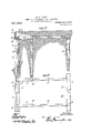
- Figures 1 and 2 are a section and plan of one embodiment, (Fig. 1 being taken along 1-1, Fig. 2) Fig. 3 1s a front elevation generally typical of any embodiment; and Figs. 4, 5 and 6 are sections taining-wall and its constituent sheet-piling units, and of the cooperating concrete horiact' detail, and particularly specified, as to features of novelty, in the claims.
- Figs. 1 i and 2 and 1, 5 and 6 are views, similar to Figs. 1, 2, 4, 5, 6, of another embodiment, the face view, Fig. 3, being generally applicable to this also; and Figs. 1 and 2 are views similar to Figs. 1 and 2, of a typical form similar to that of Fig. 3. All the drawings except Figs. 6 and o are on a scale ofabout one to one hundred.
- the structure is located along the shore of a river or harbor, the concrete piling retaining-wall and foundation A keeping in the earth fill at the right, and protecting it from the action ofv turbulent water, at the left.
- the ore or other commodity is brought to or from the dock by ships, and by railway trains-on tracks I- on the earth-fill behind wall A.
- the complete structure 'lS a combination retaining-wall,
- the stock pile may be located at the right of Fig. 1; or it may be located in place of tracks I, and furnaces may be located at the right of Fig. 1;or any other suitable arrangement may be adopt-ed.
- Figs. 1 and 2 consists essentially of the retaining-wall A consisting exclusively of the specially-constructed concrete piling units shown in detail in Figs. 2, 3 and 5, and of the top concrete horizontal-beam B, particularly the lower right hand part thereof, Fig. 1, which is centered over wall A and which transversely engages with all the several concrete piling units of the'wall, as by way of recess R, to
- Units A themselves are about forty feet high, and extend several feet above high water into horizontal-beam B, the bottom of which is about three feet above high water and about thirty feet above the mud-line at the wall A.
- the result is that. about thirty feet of the wall, constituted exclusively of concrete piles, is exposed to the horizontal load of the earth-fill on one side, and that that extent of thirty feet of individually-vertical units is entirely unsupported on the other side, except by the water.
- the units A may severally resist, without bulging or breakage,. the greathorizontal thrust on their thlrty feet or more of exposure to the load of the earthfill, they are specially constructed as follows.
- a plurality of steel bars X (Figs. 3 and 5) of about seven-eighths of an inch in diameter.
- the four bars near the sea-face of the-unit (left, Figs. 1 and- 5) take, by tension, the horizontal-thrust.
- the relative arrangement of these bars is preferably as shown in Fig. 3, z.
- those in the corners extend the entire length of the unit (forty feet), or at least into the horizontal-beam B and below the mud-line; and those bars between the corners are thirty and twenty feet long, respectively, and located so that they extend equidistantly from the vertical center of the unit, one bar for fifteen feet above and below said center and the other bar for ten feet above and below said center.
- the unit has four bars acting against the effect of the horizontal thrust; for five feet above and below the ends' of the shortest bar it has. three bars, and for the rest of its exposure to the horizontal thrust, but nearer the horizontal-beam B and the mud-line, it has two bars.
- the units are of solid masses of concrete, in order to provide, maximum -re- All this adequately provides for the efiect of the hor izontal thrust, which gradually increases toward the vertical center of the unit from the" parts of'the unit which are supported in hor. izontal beam .B and below the mud line; particularly in connection with the special construction of the joint-faces of the adjacent units, as shown in Fig. 2, and to be described.
- the units .A have a substantial width, of eighteen inches or more, and their joint-faces are formed with integral concrete longitudinally-interlocking hooks A preferably as shown.
- the feature of the'longitudinal interlocking ofthe pile-units in this invention is of great importance, in that it not only pro vides a permanently tight wall, after the horizontal-beam B is emplaced, but also holds the units longitudinally in place during the installation" of the wall and prior to the emplacement of beam B.
- the hooks A also keep the units from transverse movement in one direction, and if desired, transverse movement in the opposite direction is prevented by similar or equivalent means.
- each sheet-piling unit In addition to the left hand row of reinforcing bars X (Fig. 5) in each sheet-piling unit, it is desirable to have also a righthand row, located near the right hand face of the unit, as shown, to assist the concrete of the piling unit in resisting the strains of compression which are exerted by the horizontal loads on the land side of the sheet piling, and to cooperate with the left-hand row of bars in transmitting said horizontal loads to the top beam B and in generally stiffening the piling and in additionally strengthening the units to enable them to withstand the strains incident to handling prior to and during their installation. It is also advisable to provide the sheet pilingunits A with the integrally-molded quarterinch steel hoops shown at A Figs.
- the wall A is installed prior to the molding in place of horizontal-beam B, the units A being molded and permit-ted to set prior to their installation.
- units Afare installed as by driving or jetting, or both, there is usually no earth-fill behind them, so that they are successively lowered through the water down to the bottom, and sunk, ust as any ordinary sheet piling installation as for jetting, etc., except that the integral con- ,crete hooks A on their joint faces, permit a unit to be su'nkin alinement with a previously-sunk unit, the unit being sunk being held in place from movement either transversely or longitudinally from its adjacent unit which is already sunk.
- the hooks A also serve, during installation of the wall and prior to placing beam B and making the earth-fill, to keep the entire wall in place.
- the hooks are also of special importance in preserving tight joints between the units, to prevent the passage of solid or'semi-solid matter through the wall between the units.
- concrete units A may be so placed that their greater dimension is in the line of the piling-wall instead of across the width of the wall.
- the concrete units A are sunk so that their tops extend several feet above high water.
- the moldforms for horizontal -beam B are placed on top of it, the reinforcements placed therein, and the concrete placed in the forms around the reinforcements.
- the previously hardened or set concrete of the units A renders them permanent and independent of the alternate action of Water and air on their upper portions.
- the extension of units A substantially above high water permits the concrete of beam B to set or harden independently of the alternate action of high water and frost in air, so that the concrete of beam B is of a permanent character. the entire beam B shown, Fig.
- Beam B including its upward extension as a vertical wall preferably has also a right hand row of similar and similarly disposed and extending bars 0, but located on its tension side relative to horizontal loads from the left such as occasional shocks from shipping.
- Beam B preferably has also a plurality of sets of half-inch steel bars P extending vertically, and at intervals of about a foot and a half along the entire length of the beam, these bars resisting vertical and horizontal shearing strains.
- the load on top of B can be increased to an enormous weight, because the height, or depth, of beam B distributes a load at a given point on it, over a considerable number of successlve piling unlts A.
- buttress-and-anchor connections in the form of walls C, of concrete, and having reinforcements comprising a set of half-inch steel bars K arranged vertically near each of its sides, and also, near each of its sides, a set of half-inch steel bars L arranged horizontally and extending into and through beam B.
- Retaining-wall A by virtue of the special construction of, its units, above described, and also because it has a footing of considerable width as compared with thin sheet piling, cooperates with buttress-walls C in buttressing beam B- from overturn from off wall A. No buttress-wall is needed for each or any concrete piling unit of the wall A, this also being due to the special construction of units A.
- Walls C like beam B, are molded in place above high water, although on occasions it may do no harm if a portion of them be. molded near the surface but just below it,
- Walls C are preferablymolded integrally with beam B. They constitute a skeleton buttress, and permit beam B to be quite narrow, thus not only saving concrete but reducing the vertical load on wall A. Walls C may be solid from top to bottom, but their buttressing action is due to the fact thattheir upper and' lower points of connection (Fig. ,1) with beam B area considerable distance apart, and that the walls themselves extend back a considerable distance from beam B (to the right, Fig. 1).
- the mold-forms-for walls C may rest on piles E, which may be ordinary wood piles, and need not be concrete piles because their tops need not extend above water level.
- piles E are left in place so that they serve as buttress-piles for Walls C, and as anchors, by way of walls C acting as ties,
- Walls C ar permitted to be limited so as not to extend below the surface, by virtue of the secondary anchorage to the rear of anchor-piles E. Likewise walls C are connected to the secondary anchorage by beams If, preferably of concrete molded in place,
- the wall A and beam B take care of the traveling crane; but this is as to only one leg of the latter.
- a rear structure corresponding generally with the front structure A, B, except that in place of wall A there are simply two series of ordinary wood piles H, (and preferably batter piles H the piles serving to support the beam G, in the form of a vertical wall, which takes the weight of the crane and distributes it among the several piles, the piles H being preferably staggered, as shown, in order to better dis-- tributetthe vertical loads.
- G a plurality of horizontally-disposed one-inch steel bars S are arranged in a vertical row and extend longitudinally of G near its right-hand face and comparatively .close together, chiefiy' to take, by tension,
- G is also a skeleton part, relative to the functions zit serves, (taking the horizontal load from has considerable mass; and if a naturally-.
- Bea-ms F and G are preferably molded i place, as in the case of beam B and walls C, the mold-forms for F and G being sup- I ported 0n piles Eand H, and on any earth existing under G and under the right hand ends of F.
- F and G are molded integrally with walls C and-beam B.
- the upper bars J near thetop surface of the concrete beams F, are inclined upwardly to the eft as shown, as to their Cportions which extend through the section of concrete about two feet high and fifteen inches wide, and wit-h its reinforcement has ample strength to carry vertical loads such as the earth-fill and transverse railways; and the bars-J, which are located at top and bottom of beam F, and anchored at" the rear in beam G, also provide ample te nsional resistance to any tendency to upward or downward 'movement 'of wallQ sunk in the mud, as shown.
- Beam F has a cross-- caused by a tendency of the load on beam B to overturn it.
- Fig. '3 is an elevation of the seaward face of the'front structure consisting simply of wall A and that chief part of the beam B which acts as, a horizontal-beam. .In many cases, however, it is desirable to provide a seaward overhang from beam B, for various purposes.
- Fig. 1 a part M of concrete is molded integrally withbe'am B and isactually a art thereof, but used chiefly as a support or bollards for ships--] hawsers, as shown.
- Figs. 1 and-2 are parts of concrete is molded integrally withbe'am B and isactually a art thereof, but used chiefly as a support or bollards for ships--] hawsers, as shown.
- beam B is vertically extended simply serve as a convenient front wall for the docks.
- M (Fig. 1) has reinforcements to resist I shearing strains, consisting of a number of half-inch steel bars Q looped around near- .its surface and extending into the part of beam B which is centered over A, these looped bars being about a foot and a half] apart along the length of M and B. M extends throughout the length of beam B,
- piles D being here desirable to so serve, on account of the'enormous load on beam B, the beam being extended up- (Similarly in' wardly as'a wall in order to distribute this load over a plurality of units A. Also piles D cooperate with piles E, by way of-beam B,
- piles D when used, ma cooperate with wall A in' taking the vertlcal load of beam B as a Twhole. But the cooperation of piles D is not needed in respect of the almost unlimited vertical loads which A iscompetent to take, any more than it is needed adjacent to A place in such H in cases where itmay to buttress A against the horizontal load.
- the retaining-wall composed of the units A constructed as above, as shown in faceview in Fig. 3 without auxiliary piles, is
- each pile D extends up three feet into concrete member B, C, as shown, to resist handling strains; and they may have also the quarter inch steel hoops shown, (Fig. 1) located about a foot and a half apart along their length, to assist in column reinforcing, when desired, and in taking handling strains.
- Fig. 1 the quarter inch steel hoops shown, located about a foot and a half apart along their length, to assist in column reinforcing, when desired, and in taking handling strains.
- the four corner bars Y in each pile D extend up three feet into concrete member B, C, as
- piles D are'cast and allowed to completely set or harden above surface, preferably; but, not being 10- cated adjacent to each other and requiring tight joints, as in the case of the sheetpiling A, they need not be sunk in direct engagement with the earth, but may be lowered into a hollow hole-formerfirst sunk into place, as by a pile-driver operating abovesurface; or, they may be molded in hole-former, first sunk, the latter serving, during the setting of the concrete, to keep the water away from the concrete lying between the varying water-levels, all as is well known in this art.
- the distance of Figs. Qand 3, between the centers of piles D and buttress-walls C is a little less than thirty age may be of hundreds of feet, but this is feet.
- theconcrete structure preferably throughout, is essentially of true reinforced concrete (as distinguished from a mere concrete-protected combination of structural steel), in which neither the concrete alone nor the steel reinforcements alone need take all the strains, and in which preferably no expensive structural steel is used, but only the small separate steel bars or rods, preferably and usually in the form of bars averaging less than an inch in diameter.
- the general arrangement of the parts and the disposition of the reinforcements are such that the concrete elements are permissibly in-skeleton form, as distinguished from greater masses required prior to my inventions; and particularly, the entire structure has two main parts, first, the substructure below the level of high-water and below the normal surface of the land, consisting of the most important element, the sheet-piling of concrete piling-units,.all sunk in place in separate vertical units each of which is pro-.
- the second main part i. e., the superstructure, including essentially the horizontal-beam, located above the surface of'land and water, and consisting, preferably entirely, of reinforced concrete, molded in place, preferably into a single unitary or integral structure.
- the higher levels have either required the intermittent temporary suspension of the operation of installing structures prior to mlne, or at least i i i below the surface of land or water, were the cause of serious trouble and expense; in the case of land, on account .of the excavation required; and in; the case of water, on account of the difficulties in manipulating mold-forms down in the water, or the great expense of caissons orv heavy columns.
- Structures embodying this invention avoid all the above disadvantages by virtue of the fact that all or substantially all concretemolding is permissibly and preferably done above the surfaces of naturally-existing land and of high water, notwithstanding that the entire structure, including all or most of the parts below surface, and especially those located between-high and low water, arealso permissibly and preferably of reinforcedconcrete molded and set prior to being placed.
- the retaining-wall structure of this invention absolutely permanent in character, capable of taking the great horizontal and vertical loads indicated above, and consisting of the economical combination .of materials described, has proved of great value as a highly useful and novel proposition.
- the embodiment of the invention which is shown in l igsll and 2 etc, on Sheets 4: and 5, is in substance the same as that of Sheet 1, except the modification of buttress Wall C and its intermediate support on piles E; and in many respects this embodiment is likethat of Sheet 1, even in details.
- This embodiment is an excellent illustration of the capabilities of use of the invention in establishing a structureadapted not only for very heavy loads but also for location at a place where no land previously existed.
- the molded. reinforced concrete superstructure is placed on the sheet piling A and on the various piles, all of which are placed in nearly twenty feet of water, the till being afterward made behind the sheetpiling A. Even the rear piles H, H haveonly their lower ends engaging in the earth,
- the structure prior to the making of the fill. Thatis, the structure permits land-reclamation throughout its length, and, in addition, very heavy loads, such the crane-way bulkhead and ore-dock shown.
- the walls 0 and beams F of Sheet 1 are combined to form the deep buttress-wall C F extending from front beam B to rear beam G so that beam G is buttressed against overturn, as well as front horizontalsbeam B That is, either the beams F of Sheet 1 are increased in depth, or else the walls C of Sheet 1 are increased in length, so that-at F Sheet 1 Fig. 1, they buttress rear beam G from overturn by its load, just as C in Sheet 1 buttressed front beam B, and just as the part C of wall F in Fig. 1*, buttresses front beam B Walls C F also have a special support on piles E, intermediate beams B and C to be described.
- buttress-piles D ismade transversely continuous, instead of being intermittently extended to the left as at B, C, Sheet 1; but there is no significance in this, except that the moldforms were not so located here as to obtain the maximum economy of concrete which the invention permits, as was done in Fig. 1.
- Piles D are the same as piles D of Sheet 1, and the parts of beam B which rest on them are in effect left-hand extensions of buttress-walls C F
- Piles E, H and H are of wood, like piles E and H of Sheet 1.
- Piles E are located further toward beam G than are piles E on Sheet 1, so that they can cooperate with piles H, .H as buttress-piles for part F of the entire buttress-wall C, F; wood piles H being inclined or ,batteredas shown, to assist in the buttressing action. Piles E also cooperate with piles l) in assisting the butt-ressing action of part C of the entire buttress-wall C, F All the piles D, A, E, H and H serve as supports for the mold-forms for the superstructure, as there is no initial fill, even at the rear, on which those forms might be supported. Railways I, as before, may be placed on top of the subsequent fill to the right of wall A.
- the bars N of beam B have the same function as bars N of beam B of Sheet 1; although their location in Sheet 4:, on the tension side of the horizontal beam B (relative to the horizontal load of the subsequent fill), happens to be beyond piles D to the left, this being due simply to the immaterial transversely-c-ontinuous extension of beam B to the left, explained above.
- Piles D here, as in Sheet 1, take no part in sustaining the vertical load on beam B which is centered over piling A; but only take the load of that part of beam B which extends off the center of the vertical load,
- the reinforcements S, T, U and V are substantially the same as S, T, U, V of Sheet 1; but in Sheet 4, two additional sets of stirrups V are used, one at top and one at bottom, on account of the modified shape of beam G as compared with beam G, Sheet 1;
- Piles H of sheet 4 are in a closely continuous row (Fig. 2 and certain of batter piles H. at the left of piles H are staggered with respect. to piles H at the right of piles H. Between each pair of walls C F there are four more piles Hat the left of piles H than at the right, because piles H at the left assist beam G in anchoring the horizontal load conveyed by walls C F from beam B in addition to sustaining the vertical load on G and in addition to serving as buttress-piles cooperating with buttress-walls C, F to buttress beam G Piles E, serving as buttress-piles for wall C, F extending to left and right from said piles E, also serve to take a substantial part of the vertical load of saidwall. There is a pair of these piles E for each wall C, F,
- Stirrups Z are embedded in cradle 'VV, and' stirrups- Z in wings .W Relative to these wings W the piles E of each pair are buttressiles' in addition to being buttresspiles or the wall C F itself. If the length of .wall 0 F requires it, additional sets of piles E and cradlesW, to take the weight of the wall as a vertical-beam, may be located between beams B and G It may be possible, in an inferior form of the structure additional to and including wall A and beam B, (in the case of anyof the drawings)", to omit the continuity of the F or G, making the essential connections by way of the reinforcements where concrete is not desirable for.
- beams F might be modified in various ways and yet retain their functions of cooperating with walls C in buttressing and anchoring the horizontalbeam' B.
- wall-units A considered as parts of the entire structure shown, might have their portions below water of other construction or material than as shown and described herein, so long as their parts above low water are of concrete. Other examples might be given, but that is believed to be sutficient to explain the situation.
- wall A to take vertical terlock or guide in both transverse directure, which comprises aseries of substantially solid concrete piling units individually penetrating down into the earth bottom and extending up above the bottom substantially to the surface, and arranged successively adjacent to each other in a row and longitudinally interlocking, to constitute a tight sheet-piling retaining-wall of concrete; and a concrete horizontal-beam maintained in position transversely along the upper portion of the retaining-wall and cooperating therewith to take the horizontal loads from the respective individual constitutent concrete piling units thereof; the concrete of said horizontal-beam having embedded in it. means disposed horizontally.
- the combination-with a series of concrete piling units individually penetrating down into the earth bottom and extending up above the bottom substantially to the surface, and arranged successively adjacent to each other in a row to constitute a sheet-piling retaining-wall of concrete; of a concrete horizontat-beam maintained in position transversely along the upper portion of the retainingwall and cooperating therewith to take the horizontal loads from the respective inch vidual, constituent concrete piling unlts thereof; concrete buttress-walls extending from the horizontal-beam; and buttress-piles separated from the retaining-wall, but 10- cated beneath and extending up to the but'- tress-wall, and cooperating with the individual units of the retaining-wall 1n buttressing the horizontal-beam.
- a retaining-wall structure the combination with a series of concrete piling units individually penetrating down into the earth bottom and extending up above the bottom substantially to the surface, and arranged successively adjacent to each other in a row toconstitute a sheet-piling retaining-wall ,of concrete; of a vertical concrete wall maintained in position transversely along the top of said retaining-wall,whereby loads'on the former are distributed over the bottom substantially to the surface, and
- a retaining-wall structure the combination with a series of concrete piling units individually penetrating down into theea-rth bottom and extending up above the bottom substantially to the surface, and arranged successively adjacent to each other .m a row to constitute a sheet-piling retaining-wall of concrete; of a concrete horizontal-beam maintained in position, transversely along the upper portion of the retaining-wall and cooperating therewith to take the horizontal loads from the respective individual constituent concrete piling units thereof, concrete buttress-walls extend ng from the horizontal-beam"; an anchorage in rear of the buttress-walls and located substantially at the surface; and ties also located substantially at the surfaceand connecting the anchorage and buttress-walls.
- the com- I bination with a series of concrete piling units individually penetrating down into the earth bottom, and extending up above the bottom substantially to the surface, and arranged successively adjacent to each other in a row to constitute a sheet-piling retaining-wall of concrete; of a concrete horizontal-beam maintained in positibn transversely along the upper portion of the retaining wall and cooperating therewith to take the horizontal loads from the respective individual constituent concrete piling units thereof; concrete buttresspiles separated from the retaining wall and from each other but located beneath and extending up to the horizontal beam; concrete buttress-walls extending from the horizontal-beam; said buttress-piles and buttress-walls cooperatin with each other and with the individua units of the retaining-wall, in buttressing the horizontal-beam; an anchorage in rear of the buttress-walls and located substantially atthe surface; and ties also located. substantially at the surface, and connecting the anchorage and buttress-walls.
- a retaining-wall structure the combination with a series of concrete piling units individually penetrating down into the earth bottom and extending u above the bottom substantially to the sur ace, and arranged successively adjacent. to each other in a row to constitute a sheet-piling retaining-wall of concrete; of a concrete horizontal-beam maintained in position transversely along the upper ortion of the retainingfwall and cooperating therewith to take the horizontal loads from the respective individual constituent concrete piling units thereof; concrete buttress-walls extending earth bottom and extending u bottom substantially to the sur ace, and arfrom the horizontal-beam; buttress-piles separated from the retaining wall, but located beneath and extending up to the buttresswalls, and cooperating with the individual units of the retaining-wall in buttressingthe horizontal-beam; an anchorage in rear of the buttress-walls and located substantially at the surface;and ties also located substantially' at the surface and connecting the anchorage and buttress-walls.
- concrete piling unit In a retaining-wall structure, the combination with a series of concrete piling units individually penetrating down into the earth bottom and extending u above the vidual constituent. concrete piling unit's thereof; concrete buttress-walls extending from the horizontal-beam; concrete buttresspiles separated from the retaining-wall and from each other, but located in front of the retaining-wall beneath the horizontal-beam and extendingup to the horizontal-beam and cooperating with the buttresswalls and with the individual units of the retainingwall in buttressin'g the horizontal-beam; buttress piles in rear of and separated from the retaining-wall, but located beneath and extending up to the buttress-walls; an anchorage in rear of the buttress-walls and located substantially at the surface; and ties also located substantially at the surface and connecting the anchorage and buttress-walls.
- a retaining-wall structure the combination with a series of concrete piling units individually penetrating down into the above the ranged successively adjacent to each other in a row to constitute a sheet-piling retaining-wall of concrete; of a concrete horizontal-beam maintained in: position transversely along the upper ortion of the retainingwall, and cooperating therewith to take the horizontal loads fromthjerespective individual constituent concrete piling units thereof; concrete buttress-walls extending from the horizontal-beam; concrete buttresspiles separated from the retaining-wall and from each other, but located in front of the retaining-wall beneath the horizontal-beam v and extending up to the vhorizontal-beam and cooperatin with the buttress-walls and with the individual units of the retainingwall in buttressing the horizontal-beam; buttress piles in rear of and separated from the retaining-wall, but located :beneath and extending up to the buttress-walls; a reinforced concrete rear anchorage located substantially at the
Description
M. M. UPSON.
CONCRETE FILING RETAINING WALL STRUCTURE.
APPLICATION FILED JUNE 13, 1910. v
- Patented Jan. 17, 1911.
5 SHEETS-SHEET 1.
Inventor jlfizwdl M. V m
M. M. UPSON. CONCRETE FILING RETAINING WALL STRUCTURE.
APPLICATION FILED JUNE 13, 1910.
' Patented Jan, 17, .1911.
5 SHEETS-SHEET 2.
1 fl iii;
Inventor: Maxweflfl-W M tt nu J T \NRMN M. M. UPSON.
CONCRETE FILING RETAINING WALL STRUCTURE. APPEIOATION FILED JUNE 13, 1910. 1 981,8221 Patented 1.1111 17,1911.
' 5 SHEETSSHEET s. /29
% 1-111 1 111%! 1.111.,.11 1 |11--111|1 1.1 1.111111111w 1 1 1ri11 .H 1 A. 1 1 H .mm .H HM AH U pwwwmww H 1 1 1 1 I J 2 1 J M. M. UPSON. CONCRETE FILING RETAINING WALL STRUCTURE.
APPLICATION FILED JUNE 13, 1910.
Patented Jan. 17, 1911.
5 SHEETS-@HEET 4.
Inventor:
M. M. UPSON. GONORETE FILING RETAINING WALL STRUCTURE.
. APPLIOATiON-FILED JUNE 13, 1910. 981,822.
Patented Jan. 17', 1911.
5 SHEETS-SHEET 5.
A in venmr flamwzml gnaw s'rArEs MAXWELL M. UPSON, OF ENGIiEWOOD, NEW JERSEY.
CONCRETE-FILING RETAINING-WALL STRUCTURE.
Application filed June 13, 1910. Serial No. 566,591.
To all whom it may concern:
Be it known that I, MAXWELL M. UPsoN, a citizen of the United States of America, and a resident of Englewood, New Jersey, have invented certain new and useful Improvements in Concrete-Piling Retaining- Wall Structures, the principles of which are set forth inthe following specification and accompanying drawings, which disclose the form of the invention which I now consider to be the best of the various forms in which the principles of the invention may beembodied.
This invention relates to. concrete-piling bulkheads or retaining-wall structures particularly adapted for installation adjacent to or in water-courses, especially involving the use of reinforced-concrete as distinguished from timber or structural steel, particularly when such retaining-wall is subjected to great horizontal loads as of reclaimed land behind the retaining-wall or of a breakwater-fill, or to heavy vertical loads as of, traveling cranes or other corres'pondingly-heavy vertical loads on oredlocks, etc., and particularly where the structure is exposed to the alternate action of high and low water-levels, as of tides, especially during installation.
The general object of the invention is' a strong and permanent structure of economical cost which shall be adequatefor the stated conditions of materials used, of loads imposed, and of variations of waterlevel, or any of them.
The invention is embodied in the retaining-wall structure disclosed herein, wherein the sheet-piling wall itself iscomposed of,
piling units of concrete, but having such construction that they constitute a longitudinally-interlocked tight wall, and that they have sufiicient strength, as individuals, to
take absolutely all of the horizontal load,
and also, if desired, to take all the vertical load of and on the concrete superstructure or horizontal-beam; and also, that the concrete units. of the sheet-piling wall have sufficient strength, in cooperationwith the horizontal-beam, and preferably but not necessarily the buttress-walls, ,to serve to buttress the entire structure, even in the absence. of any extra piles which may otherwise be used to assist the buttress-walls in preventing the horizontal-beam from overturning from off theconcrete-pile retainingwall. In other words, the lnvention is a perfected formof a concrete-pile-and-concrew-superstructure, in which the entire retaining-wall, from penetrating points down below mud-line and up to surface, consists of concrete piles.
Since each individual concrete sheetpiling unit must be, and is in accordance with this invention, of such strength that the sheet-piling exclusively may take the horizontal load, these concrete units are also strong enough to take greatly increased vertical loads; and also, since they are located, in the sheet-piling, continuously adjacent to each other, it is. possible, by suitable construction of their concrete superstructure or horizontal-beam, for enormous loads to be imposed upon them, by distributing a given load over a large number of continuously adjacent piling units; and also the units, being interlocked longitudinally along the line of the wall, are functionally the equivalent of a solid concrete wall, but in addition possess the great advantage of installation as separate pre-molded units. Also these concretepiling units, having substantially wide and deep footings, as distinguished from slabs or similar sheet units, themselves serve as buttress-piles, preferably cooperating with the buttress-walls to make rigid the entire structure, no buttresspiles in front of the sheet-piling wall being necessary, except that the same may be desirable in some cases to assist in maintaining' the vertical alinement of the concrete superstructure carrying unusually great vertical loads.
'(Dne of the most notable facts concerning the invention is the simplicity of construction which it permits, the same resulting in great' economy of materials and labor of installation. In some cases even the usually important concrete buttress-walls may be" dispensed with, by reason of the great strength and stability of the concrete rezontal-beam.
The invention consists of the embodiments hereinafter described in full and ex- Of the drawings, Figures 1 and 2 are a section and plan of one embodiment, (Fig. 1 being taken along 1-1, Fig. 2) Fig. 3 1s a front elevation generally typical of any embodiment; and Figs. 4, 5 and 6 are sections taining-wall and its constituent sheet-piling units, and of the cooperating concrete horiact' detail, and particularly specified, as to features of novelty, in the claims.
of parts, Fig. 5 being enlarged; and Figs. 1 i and 2 and 1, 5 and 6 are views, similar to Figs. 1, 2, 4, 5, 6, of another embodiment, the face view, Fig. 3, being generally applicable to this also; and Figs. 1 and 2 are views similar to Figs. 1 and 2, of a typical form similar to that of Fig. 3. All the drawings except Figs. 6 and o are on a scale ofabout one to one hundred. In the case shown in Figs. 1 and 2, the structure is located along the shore of a river or harbor, the concrete piling retaining-wall and foundation A keeping in the earth fill at the right, and protecting it from the action ofv turbulent water, at the left. The ore or other commodity is brought to or from the dock by ships, and by railway trains-on tracks I- on the earth-fill behind wall A. In the case of this installation, the complete structure 'lS a combination retaining-wall,
' bulkhead. dock and crane-way. The stock pile may be located at the right of Fig. 1; or it may be located in place of tracks I, and furnaces may be located at the right of Fig. 1;or any other suitable arrangement may be adopt-ed.
The installation shown in Figs. 1 and 2 consists essentially of the retaining-wall A consisting exclusively of the specially-constructed concrete piling units shown in detail in Figs. 2, 3 and 5, and of the top concrete horizontal-beam B, particularly the lower right hand part thereof, Fig. 1, which is centered over wall A and which transversely engages with all the several concrete piling units of the'wall, as by way of recess R, to
take the respective horizontal thrusts on the several units, and thereby take care of the entire horizontal load on the upper portion of the wall as a whole. The entire horizontal load on the lower portion of the wall as a. whole, constituted of the respective hori-. zontal thrusts on the concrete piling units A, is taken by the earth below the mud-line, into which the units A penetrate, in the case shown, to a depth of ten feet, more or less. This depth of penetration insures a wallfooting which is more eifective and less expensive than any other outside of my ,i-nventions of this and prior applications and pat ents of mine. It also insures against the. passage of material beneath the wall. Units A themselves are about forty feet high, and extend several feet above high water into horizontal-beam B, the bottom of which is about three feet above high water and about thirty feet above the mud-line at the wall A. The result is that. about thirty feet of the wall, constituted exclusively of concrete piles, is exposed to the horizontal load of the earth-fill on one side, and that that extent of thirty feet of individually-vertical units is entirely unsupported on the other side, except by the water.
sistance, to compression strains.
In order that the units A may severally resist, without bulging or breakage,. the greathorizontal thrust on their thlrty feet or more of exposure to the load of the earthfill, they are specially constructed as follows. Into the molds for the concrete units are placed a plurality of steel bars X (Figs. 3 and 5) of about seven-eighths of an inch in diameter. The four bars near the sea-face of the-unit (left, Figs. 1 and- 5) take, by tension, the horizontal-thrust. The relative arrangement of these bars is preferably as shown in Fig. 3, z. e., those in the corners extend the entire length of the unit (forty feet), or at least into the horizontal-beam B and below the mud-line; and those bars between the corners are thirty and twenty feet long, respectively, and located so that they extend equidistantly from the vertical center of the unit, one bar for fifteen feet above and below said center and the other bar for ten feet above and below said center. Thus for ten feet above and below said center, the unit has four bars acting against the effect of the horizontal thrust; for five feet above and below the ends' of the shortest bar it has. three bars, and for the rest of its exposure to the horizontal thrust, but nearer the horizontal-beam B and the mud-line, it has two bars. Also the units are of solid masses of concrete, in order to provide, maximum -re- All this adequately provides for the efiect of the hor izontal thrust, which gradually increases toward the vertical center of the unit from the" parts of'the unit which are supported in hor. izontal beam .B and below the mud line; particularly in connection with the special construction of the joint-faces of the adjacent units, as shown in Fig. 2, and to be described. The units .A have a substantial width, of eighteen inches or more, and their joint-faces are formed with integral concrete longitudinally-interlocking hooks A preferably as shown. By interlocking the units, parts of the thrust at a given point on one unit are transmitted to adjacent units, so
that those parts of the thrust are distributed among a plurality of units, the result being that the several units act cooperatively as a wall as distinguished from units acting entirely independently. .And by'means of the bars X, the effect of a horizontal thrust at a given point of 'a unit is transmitted upward or downward along the unit to horizontal-beam B or below the mud-line, and, by means of the integral concrete h oks, to adjacent units; so that all tendencies; to bendor break are overcome,
The feature of the'longitudinal interlocking ofthe pile-units in this invention, is of great importance, in that it not only pro vides a permanently tight wall, after the horizontal-beam B is emplaced, but also holds the units longitudinally in place during the installation" of the wall and prior to the emplacement of beam B. The hooks A also keep the units from transverse movement in one direction, and if desired, transverse movement in the opposite direction is prevented by similar or equivalent means.
In addition to the left hand row of reinforcing bars X (Fig. 5) in each sheet-piling unit, it is desirable to have also a righthand row, located near the right hand face of the unit, as shown, to assist the concrete of the piling unit in resisting the strains of compression which are exerted by the horizontal loads on the land side of the sheet piling, and to cooperate with the left-hand row of bars in transmitting said horizontal loads to the top beam B and in generally stiffening the piling and in additionally strengthening the units to enable them to withstand the strains incident to handling prior to and during their installation. It is also advisable to provide the sheet pilingunits A with the integrally-molded quarterinch steel hoops shown at A Figs. 1 and 5, these being disposed horizontally, and located, in the example shown, about a foot and a half apart along the length of the unit. These hoops serve to reinforce the piling-unit against the strains of horizontal shear between the top and bottom supports, and they cooperate with the bars X in taking the strains incident to handling the unit in getting it into position for sinking, and during sinking, particularly if driving blows be then administered to it.
The wall A is installed prior to the molding in place of horizontal-beam B, the units A being molded and permit-ted to set prior to their installation. When units Afare installed, as by driving or jetting, or both, there is usually no earth-fill behind them, so that they are successively lowered through the water down to the bottom, and sunk, ust as any ordinary sheet piling installation as for jetting, etc., except that the integral con- ,crete hooks A on their joint faces, permit a unit to be su'nkin alinement with a previously-sunk unit, the unit being sunk being held in place from movement either transversely or longitudinally from its adjacent unit which is already sunk. The hooks A also serve, during installation of the wall and prior to placing beam B and making the earth-fill, to keep the entire wall in place. The hooks are also of special importance in preserving tight joints between the units, to prevent the passage of solid or'semi-solid matter through the wall between the units. If desired, concrete units A may be so placed that their greater dimension is in the line of the piling-wall instead of across the width of the wall.
As is shown, the concrete units A are sunk so that their tops extend several feet above high water. After wall A is completed, the moldforms for horizontal -beam B are placed on top of it, the reinforcements placed therein, and the concrete placed in the forms around the reinforcements. The previously hardened or set concrete of the units A renders them permanent and independent of the alternate action of Water and air on their upper portions. Also the extension of units A substantially above high water, permits the concrete of beam B to set or harden independently of the alternate action of high water and frost in air, so that the concrete of beam B is of a permanent character. the entire beam B shown, Fig. 1, which is centered over wall A, is the principal part of that beam, so far asconcerns its function as a horizontal-beam, and this engages with all the several unitsof the wall (as at- R) to take the horizontal load of all the horizontal thrusts'on said several units. As the thrust on a single unit is distributed among several units and upward to beam B, so the thrust of each unit A is distributed transversely along beam B and along its reinforcement against the horizontal loads. This reinforcement consists chiefly of the lefthand vertical row of horizontally-disposed one-inch steel bars N, extending transversely along the entire length of beam B on its,
tension side relative to the horizontal load from units A and the "earth-fill. Beam B, including its upward extension as a vertical wall preferably has also a right hand row of similar and similarly disposed and extending bars 0, but located on its tension side relative to horizontal loads from the left such as occasional shocks from shipping. Beam B preferably has also a plurality of sets of half-inch steel bars P extending vertically, and at intervals of about a foot and a half along the entire length of the beam, these bars resisting vertical and horizontal shearing strains. I
From all the above it is clear that all the concrete molding of beam B may be done above. surface, and that no concrete molding of retaining-wall A is done below surface. Furthermore, not only do concrete piling-units A take all the horizontal load of the earth fill, but they take all the vertical load of and on beam .B, which is centered over the line of the piling. This they'can do, not only on account of the column-reinforcement of their bars X, but because they are located adjacent to each other so that several units support and reinforce each other in respect of a vertical load on one of them. By increasing the height of beam B, as by doubling the height up to the top of the lower vertical row of bars N. as shown, Fig. 1, (as distinguished from Fig. 3), so that the beam becomes dimensionally a wall, the load on top of B can be increased to an enormous weight, because the height, or depth, of beam B distributes a load at a given point on it, over a considerable number of successlve piling unlts A.
'In thecase shown in Fig. 1, the Weight of withstanding that the wall A is so readily made as by simply successively sinking the individual piles. The'form of Figs. 3, 1 and 2 has all the advantages of Fig. 1 except thatofthe actual utilization of the full ability of wall A to take vertical loads, as by making B in the form of a wall; the beam B of Fig. 3 being no deeper than is desirable for its function as a horizontal-beam. In cases, as in'Fig. 1-, where beam B is top-heavy, and there is a consequent danger of its overturning from ot'f the top of wall A, it is best to provide buttress-and-anchor connections in the form of walls C, of concrete, and having reinforcements comprising a set of half-inch steel bars K arranged vertically near each of its sides, and also, near each of its sides, a set of half-inch steel bars L arranged horizontally and extending into and through beam B.
Retaining-wall A, by virtue of the special construction of, its units, above described, and also because it has a footing of considerable width as compared with thin sheet piling, cooperates with buttress-walls C in buttressing beam B- from overturn from off wall A. No buttress-wall is needed for each or any concrete piling unit of the wall A, this also being due to the special construction of units A.
Walls C, like beam B, are molded in place above high water, although on occasions it may do no harm if a portion of them be. molded near the surface but just below it,
as for example, the lower right hand part of the walls. Walls C are preferablymolded integrally with beam B. They constitute a skeleton buttress, and permit beam B to be quite narrow, thus not only saving concrete but reducing the vertical load on wall A. Walls C may be solid from top to bottom, but their buttressing action is due to the fact thattheir upper and' lower points of connection (Fig. ,1) with beam B area considerable distance apart, and that the walls themselves extend back a considerable distance from beam B (to the right, Fig. 1).
The mold-forms-for walls C may rest on piles E, which may be ordinary wood piles, and need not be concrete piles because their tops need not extend above water level. Preferably piles E are left in place so that they serve as buttress-piles for Walls C, and as anchors, by way of walls C acting as ties,
for the horizontal load taken by beam B from piling units A.
Walls C ar permitted to be limited so as not to extend below the surface, by virtue of the secondary anchorage to the rear of anchor-piles E. Likewise walls C are connected to the secondary anchorage by beams If, preferably of concrete molded in place,
and preferably integral units with walls C and beam B.
In accordance with one feature of the present application, the wall A and beam B take care of the traveling crane; but this is as to only one leg of the latter. To take the load of the other leg of the crane, there is provided a rear structure corresponding generally with the front structure A, B, except that in place of wall A there are simply two series of ordinary wood piles H, (and preferably batter piles H the piles serving to support the beam G, in the form of a vertical wall, which takes the weight of the crane and distributes it among the several piles, the piles H being preferably staggered, as shown, in order to better dis-- tributetthe vertical loads. In this case a special anchorage for beams F, is dispensed with, and the crane-support G, H, is made to serve in the capacity of secondary anchorage, the wall-beam G being specially constructed to serve its two functions of anchorage and crane-support, and beams F' being anchored to G.
In G a plurality of horizontally-disposed one-inch steel bars S are arranged in a vertical row and extend longitudinally of G near its right-hand face and comparatively .close together, chiefiy' to take, by tension,
and by way of beams F, walls C and beam B, the effect of the horizontal load taken by B from wall A. Near the vertical left face of G is a vertical row of seven-eighths inch steel bars T which also extend longitudinally of G; and near the top andbottom surfaces of G, are two seven-eighths inch steel bars U, likewise extending longitudinally of G; and hoops V, of five-sixteenths inch steel, are located vertically inside Gr about ,a foot and a half apart along itsv length; all serving to strengthen G in respect of the internal strains due to the great mass of the concrete (G isnearly fourteen feet high and five feet wide) and the load ofthe crane amounting 'to nearly one hundred and fifty tons on G. Although G is also a skeleton part, relative to the functions zit serves, (taking the horizontal load from has considerable mass; and if a naturally-.
existing anchorage for F and foundation for the crane-load beconvenlent, such an I inforcements of G, or bent in the concrete ch orage will preferably be used, at least to I the extent available.
In order to rovide a continuous beam effect in G, certain of the right-hand bars S are extended over to the left as shownin Figi 2. That is, two or three of the vertical row of bars S (F ig; 1), these 2 or 3 .being'preferably alternate bars in the verright to take the-tension which exists at tical row, are bent to the left (Fig. 2) as they approach beams F, so that theyserve as additional steel located at the left and extending to and along the row S at the the left hand side of those portions of G from which beams F extend.- G-well serves to buttress the successive parallel beams F" (and thereby the successive parallel walls y yi m gethe a Bea-ms F and G are preferably molded i place, as in the case of beam B and walls C, the mold-forms for F and G being sup- I ported 0n piles Eand H, and on any earth existing under G and under the right hand ends of F. Preferably also, F and G are molded integrally with walls C and-beam B. To provide a suitable structure for beams F, thereare placed in theirwoodenforms or molds prior to the placing of the concrete,
: six inch-and-aquarter steel bars J. Three of these bars, located at the bottom, as
shown, take tension, and the three at the I top assist the concrete in taking compres- '.sion, thus giving the concrete beam coni siderable strength to act as a vertical-beam to take top loads such as the superficial fill,
' of said beam; but in the case shown, the
' wall adhesion between the bars and the three feet of concrete of G in which they are embedded, is suflicient to provide for an adequate anchorage for the horizontal pull of beam B, especially when G has adequate strength as a continuous beam (Fig. 2) as described. Quarter-inch steel hoops J are also placed in the molds for concrete beams F, about two feet apart, to take horizontal shear. The bars J extend to the left through walls C. The upper bars J, near thetop surface of the concrete beams F, are inclined upwardly to the eft as shown, as to their Cportions which extend through the section of concrete about two feet high and fifteen inches wide, and wit-h its reinforcement has ample strength to carry vertical loads such as the earth-fill and transverse railways; and the bars-J, which are located at top and bottom of beam F, and anchored at" the rear in beam G, also provide ample te nsional resistance to any tendency to upward or downward 'movement 'of wallQ sunk in the mud, as shown.
and beam B. Beam F has a cross-- caused by a tendency of the load on beam B to overturn it.
Fig. '3 is an elevation of the seaward face of the'front structure consisting simply of wall A and that chief part of the beam B which acts as, a horizontal-beam. .In many cases, however, it is desirable to provide a seaward overhang from beam B, for various purposes. Thus, here (Fig. 1), a part M of concrete is molded integrally withbe'am B and isactually a art thereof, but used chiefly as a support or bollards for ships--] hawsers, as shown. (So in Figs. 1 and-2",
beam B is vertically extended simply serve as a convenient front wall for the docks.)
M (Fig. 1) has reinforcements to resist I shearing strains, consisting of a number of half-inch steel bars Q looped around near- .its surface and extending into the part of beam B which is centered over A, these looped bars being about a foot and a half] apart along the length of M and B. M extends throughout the length of beam B,
(Fig. 2') and is supported, as a verticalbeam, upon a series ofprojections B, C,-in line 'withqwalls G and molded integrally (Similarly in Figs; 1 and 2); These projections contain reinforcing;
bars K which extend up into M. The bars with B and C.
J of beams F, which extend through walls G and beam B, also extend into B, G, where they may turn or bend: upwardly, as shown; but their extension through the fifteen feet of the concrete walls C, beam B and beamportion B, C, provides ample adhesion to enable the bars to take from beam B the horizontal load on the piling A above the footing of the latter. The projections B, C, in turn are supported on concrete piles D,
Figs. 1 and 2"). Piles D, like piles E,'co-
operate with buttress-walls C to buttress.
thebeam B and prevent its overturn from off wall A; piles D being here desirable to so serve, on account of the'enormous load on beam B, the beam being extended up- (Similarly in' wardly as'a wall in order to distribute this load over a plurality of units A. Also piles D cooperate with piles E, by way of-beam B,
in maintaining the vertical alinement of wall A. Piles D also cooperate with both E and A in maintaining the vertical rigidity of the entire structure. And finally, piles D take the vertical load of those portions of beam B, such as projections B, O, and the seaward overhang M of beam B, whlch are off the center ofwall A, but not including the crane-load here. In this respect, piles D, when used, ma cooperate with wall A in' taking the vertlcal load of beam B as a Twhole. But the cooperation of piles D is not needed in respect of the almost unlimited vertical loads which A iscompetent to take, any more than it is needed adjacent to A place in such H in cases where itmay to buttress A against the horizontal load. In the retaining-wall, composed of the units A constructed as above, as shown in faceview in Fig. 3 without auxiliary piles, is
concentrated all the strength necessary to take all the vertical as well as the horizontal loads which take effect in thevertical plane between land and water where there is nothing else to support said loads. No auxiliary piles, such as D or E, are necessary to assist A in respect of said loads, although such piles may be so used if desired, asshown.
The piles D, when used, as frequently preferred for special uses as described above,
termediate bar at each side, as shown, to resist handling strains; and they may have also the quarter inch steel hoops shown, (Fig. 1) located about a foot and a half apart along their length, to assist in column reinforcing, when desired, and in taking handling strains. In the case shown, the four corner bars Y in each pile D extend up three feet into concrete member B, C, as
shown in Fig. 1; or, as an alternative, B, C'
might be cast with an opening or recess 1n it for D, asin the case of recess R for uints A, or in the case shown of the projection of the tops of piles E into walls C, or piles H into beam G. I
As in the case of piles A, piles D are'cast and allowed to completely set or harden above surface, preferably; but, not being 10- cated adjacent to each other and requiring tight joints, as in the case of the sheetpiling A, they need not be sunk in direct engagement with the earth, but may be lowered into a hollow hole-formerfirst sunk into place, as by a pile-driver operating abovesurface; or, they may be molded in hole-former, first sunk, the latter serving, during the setting of the concrete, to keep the water away from the concrete lying between the varying water-levels, all as is well known in this art. In all such cases, such methods may be made economically by using a temporary hole-former, either by using a thin shell which may be left in place, or by upwardly withdrawing the hole-former after the concrete has set. All the above statements as-to the preparation of pilesD are applicable to piles E and be desirable to make those piles of concrete.
The distance of Figs. Qand 3, between the centers of piles D and buttress-walls C is a little less than thirty age may be of hundreds of feet, but this is feet. The entire front-- preferably in sections of under a hundred 'eet.
Striking characteristics of the entire sructure, which contribute to strength, and to economy and efficiency of the operation of installing as well as the cost of materials, are that theconcrete structure, preferably throughout, is essentially of true reinforced concrete (as distinguished from a mere concrete-protected combination of structural steel), in which neither the concrete alone nor the steel reinforcements alone need take all the strains, and in which preferably no expensive structural steel is used, but only the small separate steel bars or rods, preferably and usually in the form of bars averaging less than an inch in diameter. Also the general arrangement of the parts and the disposition of the reinforcements are such that the concrete elements are permissibly in-skeleton form, as distinguished from greater masses required prior to my inventions; and particularly, the entire structure has two main parts, first, the substructure below the level of high-water and below the normal surface of the land, consisting of the most important element, the sheet-piling of concrete piling-units,.all sunk in place in separate vertical units each of which is pro-.
vided with special reinforcements, and molded and allowed to set in air before being sunk; and the second main part, "i. e., the superstructure, including essentially the horizontal-beam, located above the surface of'land and water, and consisting, preferably entirely, of reinforced concrete, molded in place, preferably into a single unitary or integral structure. 'By thus dividing the entire concrete structure into two differently-inst-alled concrete parts, above and below surface respectively, all the difliculties of concrete-installation above enumerated are completely obviated, as will be seen, and a rigid and adequate combined structure is provided, the foundation-portion off which may consist exclusively of the retainingwall of readily sunk concrete sheet-piling units.
I have found that, in structures of this class, when the concrete, during the process of hardening or settling, is located between high and low water, so that it is alternately subjected to water-saturation at high water and to frost in air above low water, the resulting concrete is inferior and subject to progressive erosion such that it is not a proper element of a structure desired to be permanent. Furthermore, in such conditions of varying water-level, the higher levels have either required the intermittent temporary suspension of the operation of installing structures prior to mlne, or at least i i i below the surface of land or water, were the cause of serious trouble and expense; in the case of land, on account .of the excavation required; and in; the case of water, on account of the difficulties in manipulating mold-forms down in the water, or the great expense of caissons orv heavy columns. Structures embodying this invention avoid all the above disadvantages by virtue of the fact that all or substantially all concretemolding is permissibly and preferably done above the surfaces of naturally-existing land and of high water, notwithstanding that the entire structure, including all or most of the parts below surface, and especially those located between-high and low water, arealso permissibly and preferably of reinforcedconcrete molded and set prior to being placed.
In embodying the invention in its preferred forms, advantage has been freely taken of the similar coefficients of expansion of steel and concrete, of the compression strength, low cost and durability of concrete, of the tensile strength of steel, and of the effective adhesion between concrete-cement and steel; and the structure largely and in many cases preferably entirely, consists of concrete and steel, the former in relatively very large masses as compared with the latter, as distinguished from installations of structural steel provided with a protective covering of concrete; although the invention, in certain aspects, permits great economy of concrete as well as steel; all whereby the resulting structure has both maximum strength and minimum cost.
The retaining-wall structure of this invention, absolutely permanent in character, capable of taking the great horizontal and vertical loads indicated above, and consisting of the economical combination .of materials described, has proved of great value as a highly useful and novel proposition.
The embodiment of the invention which is shown in l igsll and 2 etc, on Sheets 4: and 5, is in substance the same as that of Sheet 1, except the modification of buttress Wall C and its intermediate support on piles E; and in many respects this embodiment is likethat of Sheet 1, even in details. This embodiment is an excellent illustration of the capabilities of use of the invention in establishing a structureadapted not only for very heavy loads but also for location at a place where no land previously existed. As shown, the molded. reinforced concrete superstructure is placed on the sheet piling A and on the various piles, all of which are placed in nearly twenty feet of water, the till being afterward made behind the sheetpiling A. Even the rear piles H, H haveonly their lower ends engaging in the earth,
as shown. prior to the making of the fill. Thatis, the structure permits land-reclamation throughout its length, and, in addition, very heavy loads, such the crane-way bulkhead and ore-dock shown. In this case the walls 0 and beams F of Sheet 1 are combined to form the deep buttress-wall C F extending from front beam B to rear beam G so that beam G is buttressed against overturn, as well as front horizontalsbeam B That is, either the beams F of Sheet 1 are increased in depth, or else the walls C of Sheet 1 are increased in length, so that-at F Sheet 1 Fig. 1, they buttress rear beam G from overturn by its load, just as C in Sheet 1 buttressed front beam B, and just as the part C of wall F in Fig. 1*, buttresses front beam B Walls C F also have a special support on piles E, intermediate beams B and C to be described.
In Sheet 4, concrete piles A are identical with concrete piles A of Sheet 1. Beam B is substantially the same as beam B of Sheet 1, in that its vertical extent up from A is in effect a wall; and the vertical load (of the crane-way on top of the upward extension of beam B is likewise centered over pilingwall A which engages in recess R of beam B Beam B is extended to the left at M (as B at M on Sheet 1) to serve as a support for bollards for ships hawsers. The left-hand lower extension of B, above. buttress-piles D, ismade transversely continuous, instead of being intermittently extended to the left as at B, C, Sheet 1; but there is no significance in this, except that the moldforms were not so located here as to obtain the maximum economy of concrete which the invention permits, as was done in Fig. 1. Piles D are the same as piles D of Sheet 1, and the parts of beam B which rest on them are in effect left-hand extensions of buttress-walls C F Piles E, H and H are of wood, like piles E and H of Sheet 1. Piles E are located further toward beam G than are piles E on Sheet 1, so that they can cooperate with piles H, .H as buttress-piles for part F of the entire buttress-wall C, F; wood piles H being inclined or ,batteredas shown, to assist in the buttressing action. Piles E also cooperate with piles l) in assisting the butt-ressing action of part C of the entire buttress-wall C, F All the piles D, A, E, H and H serve as supports for the mold-forms for the superstructure, as there is no initial fill, even at the rear, on which those forms might be supported. Railways I, as before, may be placed on top of the subsequent fill to the right of wall A.
In the part C of buttress-wall C", F. thereinforcements J,'K, L are similar to those of wall (I of Sheet 1; and the-part F of the extended wall contains extensions of those reinforcements, which, anchored in beam G, provide ample tensional resistance to any tendency to upward or downward loadon beam G to overturn it from off piles H, H
The bars N of beam B have the same function as bars N of beam B of Sheet 1; although their location in Sheet 4:, on the tension side of the horizontal beam B (relative to the horizontal load of the subsequent fill), happens to be beyond piles D to the left, this being due simply to the immaterial transversely-c-ontinuous extension of beam B to the left, explained above. Piles D here, as in Sheet 1, take no part in sustaining the vertical load on beam B which is centered over piling A; but only take the load of that part of beam B which extends off the center of the vertical load,
, the chief function of piles D being to assist wall G, F in buttressing beam B with respect to its overturning tendency from off A. The horizontal bars ,0. in the right hand vertical row in beam B act, as in Sheet 1,- to take the tension of shocks 'or horizontal thrusts from the seaward side of piling A or beam B. The bars or stirrups P, Q. of Sheet 1 are combined, in Sheet 4,
into a single bar or stirrup P Q having similar eflect.
In beam G of Sheet- 4, the reinforcements S, T, U and V are substantially the same as S, T, U, V of Sheet 1; but in Sheet 4, two additional sets of stirrups V are used, one at top and one at bottom, on account of the modified shape of beam G as compared with beam G, Sheet 1;
Piles H of sheet 4 are in a closely continuous row (Fig. 2 and certain of batter piles H. at the left of piles H are staggered with respect. to piles H at the right of piles H. Between each pair of walls C F there are four more piles Hat the left of piles H than at the right, because piles H at the left assist beam G in anchoring the horizontal load conveyed by walls C F from beam B in addition to sustaining the vertical load on G and in addition to serving as buttress-piles cooperating with buttress-walls C, F to buttress beam G Piles E, serving as buttress-piles for wall C, F extending to left and right from said piles E, also serve to take a substantial part of the vertical load of saidwall. There is a pair of these piles E for each wall C, F,
5 and each pair supports a cradle W (Fig. 41
which hold the long narrow wall (1, F in rigid alinement between beams 13 and G.
Stirrups Z are embedded in cradle 'VV, and' stirrups- Z in wings .W Relative to these wings W the piles E of each pair are buttressiles' in addition to being buttresspiles or the wall C F itself. If the length of .wall 0 F requires it, additional sets of piles E and cradlesW, to take the weight of the wall as a vertical-beam, may be located between beams B and G It may be possible, in an inferior form of the structure additional to and including wall A and beam B, (in the case of anyof the drawings)", to omit the continuity of the F or G, making the essential connections by way of the reinforcements where concrete is not desirable for. any purpose other than to protect the steel; and it is not necessary that all the concrete be dumped at once into all parts of the molds for said principal parts. But it is preferred to have the entire superstructure of integrally molded reinforced concrete, such that all the strains or loads are taken by their proper elements or materials, concrete or steel, and wherein, said principal parts may be molded or cast in one continuous mass of concrete and preferably in one continuing operation. And
the total elimination of structural steel and the use of concrete to take compression '"smallsteel bars, yet most of the advantageons features of the structure might be retained in a case where one ormore of the parts were made of structural steel in an attempt to obtain a beneficial use of the invention. Thus, for example, beams F might be modified in various ways and yet retain their functions of cooperating with walls C in buttressing and anchoring the horizontalbeam' B. Also, wall-units A, considered as parts of the entire structure shown, might have their portions below water of other construction or material than as shown and described herein, so long as their parts above low water are of concrete. Other examples might be given, but that is believed to be sutficient to explain the situation.
single typical form of the invention, wherein loads is not utilized, the horizontal-beam not being extended vertically on the center of wall A for the purpose of distributing vertical loads over the piles of A. Likewise there is no rear anchor-beam adapted todistribute vertical loads, but the anchor or deadman' G serves chiefly in respect of the horizontal load on beam B,. in connection with piles H. In Figs. 3, 1 and 2 where the longitudinal interlocks A do not int-ions, metal guides 2 may be used to keep the units from moving toward the right (Fig. 2). In Fig.2 said metal guides are not necessary, on account of the inclination of the pile-surface to the right of the interlocking hooks.
I claim:
1. An element of a retaining-wall strucconcrete at the joints between members B, C,-
strains, the strains of tension being taken by while an important economicadvantage of the whole structure above is that it permitsv Figs. 1 and 2 illustrate, like Fig. 3, a'
the whole ability of wall A to take vertical terlock or guide in both transverse directure, which comprises aseries of substantially solid concrete piling units individually penetrating down into the earth bottom and extending up above the bottom substantially to the surface, and arranged successively adjacent to each other in a row and longitudinally interlocking, to constitute a tight sheet-piling retaining-wall of concrete; and a concrete horizontal-beam maintained in position transversely along the upper portion of the retaining-wall and cooperating therewith to take the horizontal loads from the respective individual constitutent concrete piling units thereof; the concrete of said horizontal-beam having embedded in it. means disposed horizontally. along its length for reinforcing it against thehorizontal loads of the retaining-wall as a whole; and the concrete masses of the respective piling units having embedded in them verticallydisposed means for reinforcing the individual units against the horizontal loads along their lengths intermediate their earth-- footings and the horizontal-beam, to thereby vertically transmit the horizontal loads downwardly and upwardly.
2. In a retaining-wall structure, the con bination with a series of concrete piling units individually penetrating down into the earth bottom and extending up above the bottom substantially to the surface, and arranged successively adjacent to each other in a row and longitudinally interlocking, to constitute a tlght sheet-piling retaining-wall of concrete; of a concrete horizontal-beam maintained in position transversely along the upper portion of the retaining-wall and cooperating therewith to take the horizontal loads from the respective individual constituent concrete piling units thereof; the concrete of said horizontal-beam having embedded in it means disposed horizontally along its length for reinforcing it against the horizontal load of the retaining-wall as a whole; and concrete buttress-walls extending from the horizontal-beam and cooperating with the individual units of the retaining-wall in buttressing the horizontal-beam 3. In a retaining-wall structure, the combination with a series of concrete piling units individually penetrating down into the learth bottom and extending up above the bottom substantially to the surface, and arranged successively adjacent to each other i in a row and longitudinally interlocking, to
constitute a tight sheet-piling retaining-wall of concrete; of a concrete horizontal-beam maintained in position transversely along the upper portion of the retaining-wall and cooperating therewith to take the horizontal loads from the respective individual con stituent concrete piling units thereof; the concrete of said horizontal beam having embedded in it means disposed horizontally along its length for reinforcing it against the horizontal load of the retaining-wall as a whole; and concrete buttress-piles sepa-' bination with a series of concrete piling units individually penetrating down into the earth bottom and extending up above the bottom substantially to the surface, and arranged successively adjacent toeach other in a row to constitute a sheet-piling retaining-wall of concrete; of a concrete horizontal-beam maintained in position transversely along the upper port-ion of the retaining-wall and cooperating therewith to take the horizontal loads from the respective individual constituent-concrete piling units thereof; the concrete of said horizontal-beam having em bedded in it means disposed horizontally along its length for reinforcing it against the horizontal load of the retaining-wall as a whole; concrete buttress-piles separated from the retaining-wall and from each other but located beneath and extending up to the horizontalbeam; and concrete buttress-walls extending from the horizontal-beam; said buttress-piles and buttress-walls cooperating with each other and with the individual units of the retaining-wall, in buttressing the horizontal-beam.
5. In a retaining-wall structure, the combination-with a series of concrete piling units individually penetrating down into the earth bottom and extending up above the bottom substantially to the surface, and arranged successively adjacent to each other in a row to constitute a sheet-piling retaining-wall of concrete; of a concrete horizontat-beam maintained in position transversely along the upper portion of the retainingwall and cooperating therewith to take the horizontal loads from the respective inch vidual, constituent concrete piling unlts thereof; concrete buttress-walls extending from the horizontal-beam; and buttress-piles separated from the retaining-wall, but 10- cated beneath and extending up to the but'- tress-wall, and cooperating with the individual units of the retaining-wall 1n buttressing the horizontal-beam.
G. In a retaining-wall structure, the combination with a series of concrete piling units individually penetrating down into the earth bottom and extending up above the bottom substantially to the surface, and arranged successively adjacent to each other in a row to constitute a sheet-piling retaining-wall of concrete; of a concrete horizontal-beam maintained in position transversely along the upper portion of the retainingwall and cooperating therewlth totake the horizontal loads from the respective 1nd1- vidual constituent concrete piling units thereof; concrete buttress-walls extending from the horizontal-beam; concrete buttresspiles separated from the retaining-wall and from each other, but located beneath the horizontal-beam in front of the retainingwall and extending up to the horizontalbeam and cotiperating with the buttresswalls and with the individual units of the retaining-wall in but-tressing the horizontalbeam; and buttress-piles in rear of and separated from the retaining wall, but located beneath and extending up to the buttresswalls.
7. In a retaining-wall structure,the combination with a series, of concrete piling units individually penetrating down into the earth bottom and extending up above the bottom substantially to the surface, and arranged successively adjacent to each other in a row to constitute a sheet-piling retainingwall of concrete; of a concrete horizontalbearn maintained in position transversely along theupper portion of the retaining-wall and cooperating therewith to take the hOIlzontal loads from the respective individual constituent concrete piling units thereof a reinforced concrete rear anchorage located substantially at the surface; and reinforcedconcrete ties between the horizontal-beam and anchorage and also located substantially at the surface. V
8;In a retaining-wallstructure, the combination with a series of concrete piling units individually penetrating down into the earth bottom and'extending up above the bottom substantially to the surface, and arranged successively adjacent to each other in a row to constitute asheet-piling retainin -Wall of concrete; of a concrete horizontaI-beam maintained in position transversely along the upper portion of the retainingwall and cooperating therewithto take the horizontal loads from the respective individual constituent concrete piling units thereof; a reinforced concrete rear anchorage located substantially at the "surface; piles located beneath and extending up to the rear anchorage; and reinforced concrete ties between the horizontal-beam and the earth bottom an extending up above the bottom substantially to'the surface, and arranged successively adjacent to eachother in a row and longitudinally interlocking, to constitute a tight sheet-piling retainingwall of concrete; of a vertical concrete wall maintained in position transversely along the top of said retaining-wall, whereby loads on the former are distributed over a plurahtyof umts of the latter, said vertical concrete wall also taking the horizontal load on the retaining-wall and having embedded in it means disposed horizontally along its length for reinforcing it against such horizontal load; the concrete masses of the respective concrete piling units having embedded in them vertically disposed means for reinforcing the individual units against vertical loads on the vertical concrete Wall and against horizontal loads upon the parts of the units intermediate said vertical wall and the earth-footings of the units.
10. In a retaining-wall structure, the combination with a series of concrete piling units individually penetrating down into the earth bottom and extending up above the bottom substantially to the surface, and arranged successively adjacent to each other in a row toconstitute a sheet-piling retaining-wall ,of concrete; of a vertical concrete wall maintained in position transversely along the top of said retaining-wall,whereby loads'on the former are distributed over the bottom substantially to the surface, and
arranged successively adjacent to eachother in a row to constitute a sheet-piling retaining-wall of concrete; of averti'cal concrete wall 'maintained ,in position transversely along the top of said retaining-wall, whereby loadson the former are distributed over 'a plurality of units-of the latter, said vertical concrete wall also taking the horizontal. load on the retaining-wall; a vertical reinforced concrete wall in rear ofthe retainingwall; and reinforced-concrete buttress-walls a plurality of units-of the latter, said verlocated substantially at the surface, extending between the two vertical Walls,- and tying the same together. I
12. In a retaining-wall structure, the combination with a series of concrete piling units individually penetrating down into theea-rth bottom and extending up above the bottom substantially to the surface, and arranged successively adjacent to each other .m a row to constitute a sheet-piling retaining-wall of concrete; of a concrete horizontal-beam maintained in position, transversely along the upper portion of the retaining-wall and cooperating therewith to take the horizontal loads from the respective individual constituent concrete piling units thereof, concrete buttress-walls extend ng from the horizontal-beam"; an anchorage in rear of the buttress-walls and located substantially at the surface; and ties also located substantially at the surfaceand connecting the anchorage and buttress-walls.
13. In a retaining-wall structure, the-combination with a series of concrete piling units 'individually penetrating down into the earth bottom and extending up above the bottom substantially to the surface, and arranged successively adjacent to each other in a row to constitute a sheet-piling retaining-wall of concrete; of a concrete horizontal-beam maintained in position transversely along the upper portion of the retaining-wall and cooperating therewith to take the horizontal loads from the res ective individual constituent concrete pi ing units thereof; concrete buttress-piles separated from the retaining-wall and from each other but located beneath and extending up to the horizontal-beam; an anchorage in rear of the buttress-piles and located substantially at the surface; and ties also located substantially at the surface and connecting the anchorage and horizontal-beam.
14. In a retaining-wall structure, the com- I bination with a series of concrete piling units individually penetrating down into the earth bottom, and extending up above the bottom substantially to the surface, and arranged successively adjacent to each other in a row to constitute a sheet-piling retaining-wall of concrete; of a concrete horizontal-beam maintained in positibn transversely along the upper portion of the retaining wall and cooperating therewith to take the horizontal loads from the respective individual constituent concrete piling units thereof; concrete buttresspiles separated from the retaining wall and from each other but located beneath and extending up to the horizontal beam; concrete buttress-walls extending from the horizontal-beam; said buttress-piles and buttress-walls cooperatin with each other and with the individua units of the retaining-wall, in buttressing the horizontal-beam; an anchorage in rear of the buttress-walls and located substantially atthe surface; and ties also located. substantially at the surface, and connecting the anchorage and buttress-walls. I
15. In a retaining-wall structure, the combination with a series of concrete piling units individually penetrating down into the earth bottom and extending u above the bottom substantially to the sur ace, and arranged successively adjacent. to each other in a row to constitute a sheet-piling retaining-wall of concrete; of a concrete horizontal-beam maintained in position transversely along the upper ortion of the retainingfwall and cooperating therewith to take the horizontal loads from the respective individual constituent concrete piling units thereof; concrete buttress-walls extending earth bottom and extending u bottom substantially to the sur ace, and arfrom the horizontal-beam; buttress-piles separated from the retaining wall, but located beneath and extending up to the buttresswalls, and cooperating with the individual units of the retaining-wall in buttressingthe horizontal-beam; an anchorage in rear of the buttress-walls and located substantially at the surface;and ties also located substantially' at the surface and connecting the anchorage and buttress-walls.
16. In a retaining-wall structure, the combination with a series of concrete piling units individually penetrating down into the earth bottom and extending u above the vidual constituent. concrete piling unit's thereof; concrete buttress-walls extending from the horizontal-beam; concrete buttresspiles separated from the retaining-wall and from each other, but located in front of the retaining-wall beneath the horizontal-beam and extendingup to the horizontal-beam and cooperating with the buttresswalls and with the individual units of the retainingwall in buttressin'g the horizontal-beam; buttress piles in rear of and separated from the retaining-wall, but located beneath and extending up to the buttress-walls; an anchorage in rear of the buttress-walls and located substantially at the surface; and ties also located substantially at the surface and connecting the anchorage and buttress-walls.
, l7. In a retaining-wall structure, the combination with a series of concrete piling units individually penetrating down into the above the ranged successively adjacent to each other in a row to constitute a sheet-piling retaining-wall of concrete; of a concrete horizontal-beam maintained in: position transversely along the upper ortion of the retainingwall, and cooperating therewith to take the horizontal loads fromthjerespective individual constituent concrete piling units thereof; concrete buttress-walls extending from the horizontal-beam; concrete buttresspiles separated from the retaining-wall and from each other, but located in front of the retaining-wall beneath the horizontal-beam v and extending up to the vhorizontal-beam and cooperatin with the buttress-walls and with the individual units of the retainingwall in buttressing the horizontal-beam; buttress piles in rear of and separated from the retaining-wall, but located :beneath and extending up to the buttress-walls; a reinforced concrete rear anchorage located substantially at the surface; and reinforced concrcte ties between the buttress-walls and anchorage and also located substantially at the surface.
18. In a bulkhead, the combination with a plurality of concrete piles individually penetrating down into the earth bottom and extending up above the bottom substantially to the surface; of a vertical concrete wall located substantially at the surface and maintained in osition transversely along the tops of sai concrete piles, whereby vertical loads 011 the former are distributed over a plurality of the latter; a second vertical concrete' Wall in rear of the first, and also located substantially at the surface; a second set of piles supporting the second wall and individually penetrating down into the earth bottom; and reinforced concrete ties located substantially at the surface and extending between the two vertical walls and tying the same together.
MAXWELL M. UPSON.
Witnesses: M. V. HEALY, P. D. CASE.
Priority Applications (1)
| Application Number | Priority Date | Filing Date | Title |
|---|---|---|---|
| US56659110A US981822A (en) | 1910-06-13 | 1910-06-13 | Concrete-piling retaining-wall structure. |
Applications Claiming Priority (1)
| Application Number | Priority Date | Filing Date | Title |
|---|---|---|---|
| US56659110A US981822A (en) | 1910-06-13 | 1910-06-13 | Concrete-piling retaining-wall structure. |
Publications (1)
| Publication Number | Publication Date |
|---|---|
| US981822A true US981822A (en) | 1911-01-17 |
Family
ID=3050184
Family Applications (1)
| Application Number | Title | Priority Date | Filing Date |
|---|---|---|---|
| US56659110A Expired - Lifetime US981822A (en) | 1910-06-13 | 1910-06-13 | Concrete-piling retaining-wall structure. |
Country Status (1)
| Country | Link |
|---|---|
| US (1) | US981822A (en) |
Cited By (3)
| Publication number | Priority date | Publication date | Assignee | Title |
|---|---|---|---|---|
| US3114244A (en) * | 1958-12-29 | 1963-12-17 | Joseph R Silver | Retaining wall |
| US3255591A (en) * | 1961-08-23 | 1966-06-14 | Thornley Beatrice | Horizontally stabilized foundation |
| US4045965A (en) * | 1975-06-26 | 1977-09-06 | Vidal Henri C | Quay structure |
-
1910
- 1910-06-13 US US56659110A patent/US981822A/en not_active Expired - Lifetime
Cited By (3)
| Publication number | Priority date | Publication date | Assignee | Title |
|---|---|---|---|---|
| US3114244A (en) * | 1958-12-29 | 1963-12-17 | Joseph R Silver | Retaining wall |
| US3255591A (en) * | 1961-08-23 | 1966-06-14 | Thornley Beatrice | Horizontally stabilized foundation |
| US4045965A (en) * | 1975-06-26 | 1977-09-06 | Vidal Henri C | Quay structure |
Similar Documents
| Publication | Publication Date | Title |
|---|---|---|
| US4045965A (en) | Quay structure | |
| US3022759A (en) | Concrete floating wharf | |
| US981822A (en) | Concrete-piling retaining-wall structure. | |
| US1422821A (en) | Sheet-piling wall construction | |
| US1693311A (en) | Sea wall and method of making same | |
| US2514119A (en) | Breakwater | |
| US592738A (en) | judson | |
| US729591A (en) | Bridge-anchor. | |
| US1577885A (en) | Retaining wall | |
| US952645A (en) | Reinforced-concrete sectional sea-wall. | |
| US868092A (en) | System of construction for foundations, dams, sea-walls, and the like. | |
| JP7149919B2 (en) | Improvement structure and improvement method of existing wharf | |
| KR100664911B1 (en) | Frp soil walls | |
| US969706A (en) | Sea-wall or wharf construction. | |
| US630457A (en) | Ship-canal. | |
| US1672102A (en) | Wharf or pier | |
| US3548603A (en) | Braced frame bulkhead | |
| US705732A (en) | Retaining-wall. | |
| US1006247A (en) | Dock construction and method of constructing docks. | |
| US46146A (en) | Improvement in construction of docks | |
| US1505238A (en) | Breakwater-wall construction | |
| US1067950A (en) | Filled-in construction. | |
| GB149137A (en) | Improvements in construction of wharves and the like | |
| US1392616A (en) | Wharf-wall and the like | |
| US1298101A (en) | Bulkhead. |