US9816732B2 - Geothermal energy transfer system - Google Patents
Geothermal energy transfer system Download PDFInfo
- Publication number
- US9816732B2 US9816732B2 US14/500,016 US201414500016A US9816732B2 US 9816732 B2 US9816732 B2 US 9816732B2 US 201414500016 A US201414500016 A US 201414500016A US 9816732 B2 US9816732 B2 US 9816732B2
- Authority
- US
- United States
- Prior art keywords
- energy transfer
- transfer unit
- heat exchanger
- housing
- column
- Prior art date
- Legal status (The legal status is an assumption and is not a legal conclusion. Google has not performed a legal analysis and makes no representation as to the accuracy of the status listed.)
- Active, expires
Links
Images


Classifications
-
- F—MECHANICAL ENGINEERING; LIGHTING; HEATING; WEAPONS; BLASTING
- F24—HEATING; RANGES; VENTILATING
- F24T—GEOTHERMAL COLLECTORS; GEOTHERMAL SYSTEMS
- F24T10/00—Geothermal collectors
- F24T10/10—Geothermal collectors with circulation of working fluids through underground channels, the working fluids not coming into direct contact with the ground
-
- F24J3/081—
-
- F—MECHANICAL ENGINEERING; LIGHTING; HEATING; WEAPONS; BLASTING
- F24—HEATING; RANGES; VENTILATING
- F24T—GEOTHERMAL COLLECTORS; GEOTHERMAL SYSTEMS
- F24T10/00—Geothermal collectors
- F24T10/30—Geothermal collectors using underground reservoirs for accumulating working fluids or intermediate fluids
-
- F—MECHANICAL ENGINEERING; LIGHTING; HEATING; WEAPONS; BLASTING
- F28—HEAT EXCHANGE IN GENERAL
- F28D—HEAT-EXCHANGE APPARATUS, NOT PROVIDED FOR IN ANOTHER SUBCLASS, IN WHICH THE HEAT-EXCHANGE MEDIA DO NOT COME INTO DIRECT CONTACT
- F28D7/00—Heat-exchange apparatus having stationary tubular conduit assemblies for both heat-exchange media, the media being in contact with different sides of a conduit wall
- F28D7/04—Heat-exchange apparatus having stationary tubular conduit assemblies for both heat-exchange media, the media being in contact with different sides of a conduit wall the conduits being spirally coiled
-
- F—MECHANICAL ENGINEERING; LIGHTING; HEATING; WEAPONS; BLASTING
- F28—HEAT EXCHANGE IN GENERAL
- F28F—DETAILS OF HEAT-EXCHANGE AND HEAT-TRANSFER APPARATUS, OF GENERAL APPLICATION
- F28F9/00—Casings; Header boxes; Auxiliary supports for elements; Auxiliary members within casings
- F28F9/007—Auxiliary supports for elements
- F28F9/013—Auxiliary supports for elements for tubes or tube-assemblies
- F28F9/0131—Auxiliary supports for elements for tubes or tube-assemblies formed by plates
-
- F—MECHANICAL ENGINEERING; LIGHTING; HEATING; WEAPONS; BLASTING
- F24—HEATING; RANGES; VENTILATING
- F24D—DOMESTIC- OR SPACE-HEATING SYSTEMS, e.g. CENTRAL HEATING SYSTEMS; DOMESTIC HOT-WATER SUPPLY SYSTEMS; ELEMENTS OR COMPONENTS THEREFOR
- F24D11/00—Central heating systems using heat accumulated in storage masses
- F24D11/02—Central heating systems using heat accumulated in storage masses using heat pumps
- F24D11/0214—Central heating systems using heat accumulated in storage masses using heat pumps water heating system
-
- F—MECHANICAL ENGINEERING; LIGHTING; HEATING; WEAPONS; BLASTING
- F24—HEATING; RANGES; VENTILATING
- F24D—DOMESTIC- OR SPACE-HEATING SYSTEMS, e.g. CENTRAL HEATING SYSTEMS; DOMESTIC HOT-WATER SUPPLY SYSTEMS; ELEMENTS OR COMPONENTS THEREFOR
- F24D11/00—Central heating systems using heat accumulated in storage masses
- F24D11/02—Central heating systems using heat accumulated in storage masses using heat pumps
- F24D11/0257—Central heating systems using heat accumulated in storage masses using heat pumps air heating system
-
- F—MECHANICAL ENGINEERING; LIGHTING; HEATING; WEAPONS; BLASTING
- F24—HEATING; RANGES; VENTILATING
- F24D—DOMESTIC- OR SPACE-HEATING SYSTEMS, e.g. CENTRAL HEATING SYSTEMS; DOMESTIC HOT-WATER SUPPLY SYSTEMS; ELEMENTS OR COMPONENTS THEREFOR
- F24D2200/00—Heat sources or energy sources
- F24D2200/11—Geothermal energy
-
- F—MECHANICAL ENGINEERING; LIGHTING; HEATING; WEAPONS; BLASTING
- F28—HEAT EXCHANGE IN GENERAL
- F28F—DETAILS OF HEAT-EXCHANGE AND HEAT-TRANSFER APPARATUS, OF GENERAL APPLICATION
- F28F2240/00—Spacing means
-
- Y—GENERAL TAGGING OF NEW TECHNOLOGICAL DEVELOPMENTS; GENERAL TAGGING OF CROSS-SECTIONAL TECHNOLOGIES SPANNING OVER SEVERAL SECTIONS OF THE IPC; TECHNICAL SUBJECTS COVERED BY FORMER USPC CROSS-REFERENCE ART COLLECTIONS [XRACs] AND DIGESTS
- Y02—TECHNOLOGIES OR APPLICATIONS FOR MITIGATION OR ADAPTATION AGAINST CLIMATE CHANGE
- Y02B—CLIMATE CHANGE MITIGATION TECHNOLOGIES RELATED TO BUILDINGS, e.g. HOUSING, HOUSE APPLIANCES OR RELATED END-USER APPLICATIONS
- Y02B10/00—Integration of renewable energy sources in buildings
- Y02B10/40—Geothermal heat-pumps
-
- Y—GENERAL TAGGING OF NEW TECHNOLOGICAL DEVELOPMENTS; GENERAL TAGGING OF CROSS-SECTIONAL TECHNOLOGIES SPANNING OVER SEVERAL SECTIONS OF THE IPC; TECHNICAL SUBJECTS COVERED BY FORMER USPC CROSS-REFERENCE ART COLLECTIONS [XRACs] AND DIGESTS
- Y02—TECHNOLOGIES OR APPLICATIONS FOR MITIGATION OR ADAPTATION AGAINST CLIMATE CHANGE
- Y02B—CLIMATE CHANGE MITIGATION TECHNOLOGIES RELATED TO BUILDINGS, e.g. HOUSING, HOUSE APPLIANCES OR RELATED END-USER APPLICATIONS
- Y02B30/00—Energy efficient heating, ventilation or air conditioning [HVAC]
- Y02B30/13—Hot air central heating systems using heat pumps
-
- Y—GENERAL TAGGING OF NEW TECHNOLOGICAL DEVELOPMENTS; GENERAL TAGGING OF CROSS-SECTIONAL TECHNOLOGIES SPANNING OVER SEVERAL SECTIONS OF THE IPC; TECHNICAL SUBJECTS COVERED BY FORMER USPC CROSS-REFERENCE ART COLLECTIONS [XRACs] AND DIGESTS
- Y02—TECHNOLOGIES OR APPLICATIONS FOR MITIGATION OR ADAPTATION AGAINST CLIMATE CHANGE
- Y02E—REDUCTION OF GREENHOUSE GAS [GHG] EMISSIONS, RELATED TO ENERGY GENERATION, TRANSMISSION OR DISTRIBUTION
- Y02E10/00—Energy generation through renewable energy sources
- Y02E10/10—Geothermal energy
Definitions
- the present invention relates to geothermal, also known as geo-exchange, energy transfer systems.
- the heat pump uses a closed cycle that passes a refrigerant through an expansion phase that requires the absorption of external energy and a compression phase which rejects energy. In order to supply energy to a particular location, the rejected heat is transferred in to the heating system of that location and the energy required to effect the expansion of the refrigerant is absorbed from an external source. Similarly, when heat is to be extracted from the location, the location supplies the energy for the expansion of the refrigerant and the heat generated during compression is rejected to the external source.
- the external source may be the air itself, as is the case with traditional air conditioning units or heat pumps.
- air conditioning units or heat pumps may be the air itself, as is the case with traditional air conditioning units or heat pumps.
- such an arrangement has a poor efficiency due to fluctuations in the air temperature.
- a preferred external source has a substantially constant temperature and the ground or large body of water are typically used. Such systems are typically referred to as geo-thermal or geo-exchange systems. It is therefore known to provide a heat exchange loop between the heat pump and such a source so that heat may be absorbed in to the loop to supply energy to the heat pump or may be rejected from the loop to remove energy from the heat pump.
- the loops are typically an extensive run of pipe containing a saline, glycol or ethyl alcohol based heat exchange fluid.
- the pipe is buried in a trench between one or two meters below the normal surface. At that depth, the earth is at a substantially constant temperature and provides a energy source to either provide energy to or absorb energy from the heat transfer fluid.
- the temperature differential between the heat exchange fluid and the surroundings is small, such installations require a relatively large area, in the order of several acres, to provide the necessary surface area to effect energy transfer between the surroundings and the fluid.
- An alternative arrangement is to provide for vertical heat transfer loop which requires drilling one or more bore holes to a significant depth in order to get the necessary surface area. Both of these options, therefore, relatively expensive and may only be used in a limited number of locations.
- a large body of water may be used as the energy source.
- the heat transfer loop is placed in the water. This however may disturb environmentally sensitive areas and can be unsightly and difficult to install in an orderly manner.
- an energy transfer unit for a geothermal system.
- the energy transfer unit includes an outer housing with a heat exchanger located within the housing.
- An inlet pipe extends from the housing to the heat exchanger to convey heat transfer fluid to the heat exchanger.
- An outlet pipe extends from the housing to the heat exchanger to convey heat transfer fluid from the heat exchanger.
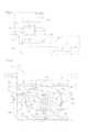
- FIG. 1 is a schematic representation of an energy transfer system
- FIG. 2 is a side elevation of a energy transfer unit used in the system of FIG. 1 ;
- FIG. 3 is a perspective view of a heat exchange unit used in the energy transfer unit of FIG. 2 ;
- FIG. 4 is a side elevation of the units shown in FIG. 3 ;
- FIG. 5 is a perspective view of an energy transfer unit during assembly
- FIG. 6 is a representation similar to FIG. 2 of an alternative embodiment of energy transfer unit
- FIG. 7 is a view similar to FIG. 2 of an energy transfer unit for installation within a body of water;
- FIG. 8 is a schematic representation of an energy transfer unit located on the surface
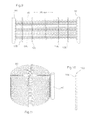
- FIG. 9 is a elevation of components used in an alternative embodiment of heat exchange unit.
- FIG. 10 is a side elevation of a component used in the assembly of FIG. 9 ;
- FIG. 11 is a perspective view of the heat transfer unit assembled from the components of FIGS. 9 and 10 .
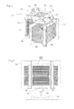
- FIG. 12 is a perspective view of a further embodiment
- FIG. 13 is a section of the embodiment of FIG. 12 ;
- FIG. 14 is an exploded perspective view of the embodiment of FIG. 12 ;
- FIG. 15 is a perspective view of the heat exchanger unit used in the embodiment of FIG. 12 ;
- FIG. 16 is a view on the line XVI-XVI of FIG. 15 ;
- FIG. 17 is a plan view of the heat exchanger unit of FIG. 15 ;
- FIG. 18 is a view on the line XVIII-XVIII of FIG. 12 ;
- FIG. 19 is a section on the line XIX-XIX of FIG. 12 ;
- FIG. 20 is a perspective view of a further embodiment.
- FIG. 21 is a section on the line XXI-XXI of FIG. 20 .
- a building 10 has a heating and cooling system 12 to distribute heat through the building or to remove heat from the building.
- the heat distribution system may be an air circulating system, or a water circulating system that transfers heat between different areas of the building and a heat source.
- the heating and cooling system 12 includes a heat exchanger 14 that cooperates with a heat exchanger 16 to transfer heat between a heat pump 18 and the building 10 .
- the heat pump 18 is of conventional construction and includes a heat exchanger 20 connected in a refrigerant loop to the heat exchanger 16 through a throttle valve 22 and a compressor 24 .
- Expansion of a refrigerant through the throttle 22 causes heat to be absorbed in to the refrigerant and compression of the refrigerant through the pump 24 causes heat to be rejected.
- the heat exchangers 16 and 20 absorb or reject the heat depending upon the mode of the operation of the refrigerant cycle.
- the heat exchanger 20 cooperates with a further heat exchanger 26 to transfer heat between the refrigerant loop and a heat transfer loop indicated at 28 .
- the heat transfer loop 28 includes a pump 30 that circulates a heat transfer fluid, typically an ethyl alcohol mixture, through a return pipe 32 and a supply pipe 34 .
- the pipes 32 , 34 are connected to an energy transfer unit 36 that operates in a manner described in more detail below to transfer energy between the heat transfer loop and the immediate surrounding indicated at T.
- the heat transfer unit 36 may be buried within the ground, may be located within a body of water such as a lake, pond or river, or may be surface mounted within an enclosure. In each case, the immediate surroundings act as an energy reservoir to receive or contribute energy to the energy transfer unit 36 .
- heat transfer unit 36 is designed to be buried within the ground T.
- a pit 40 is excavated in the ground to a depth at which a substantially constant temperature and stable water table is to be expected. In North America, a depth of between 8 and 12 feet is satisfactory.
- the energy transfer unit 36 includes an outer housing 42 that, in the embodiment shown in FIG. 2 , is spherical.
- the housing 42 is formed in two semi-cylindrical shells 44 , 46 that mate along a flange 48 .
- the housing 42 is designed to be fluid tight with a seal incorporated in to the flange 48 and to be formed from a thermal and electrically conductive material. In practice, an electrical conductivity of 10-15 w/m 2 or greater has found to be satisfactory.
- Shells made from a thermal setting resin. PTFE (polytetraflon) or polymer compound, or impregnated with electrically conductive materials such as metal strand, graphite, carbon, nano-tubes, copper mesh, or similar materials are preferred.
- a metallic or non-metallic PTFE (polytetraflon) heat exchange core 50 is located within the housing 42 on a stand 52 .
- the stand 52 has a base 54 and a post 56 that passes through a collar 58 at the centre of the core 50 .
- a pin 60 secures the collar 58 to the post 52 and maintains the core 50 in spaced relationship from the housing 42 .
- Stays 62 extend between the part cylindrical shell 44 and the core 50 to stabilize the core 50 within the housing 42 .
- the return pipe 32 and supply pipe 34 are connected to the core 50 through an inlet pipe 64 and outlet pipe 66 .
- Couplings 68 releasably secure the return and supply pipes 32 , 34 to the inlet and supply pipes 62 , 66 .
- the coupling 68 is of known construction allowing the rapid disconnection of the return and supply pipes 32 , 34 from the energy transfer unit 36 .
- the housing 42 is filled with a buffer fluid 64 b through a plug 70 that may be sealed to the housing 42 after filling.
- the buffer fluid may be water, saltwater, electrolyte or other material capable of energy transfer and may of course be pumped in to the housing 52 after installation.
- the energy transfer unit 36 is lowered in to the pit 40 and stably supported on a base of sand or other fine materials or undistributed soil T.
- the material, S supports the housing 42 and ensures a close contact between the housing and the surrounding earth T.
- the pit 40 may be filled with sands, granular material, concrete or other proprietary compounds S to completely encompass the energy transfer unit 36 .
- the fill material is chosen to ensure a close contact between the exterior surface of the housing 42 and impart good energy transfer characteristics.
- a thermal barrier 72 is inserted into the pit during back-filling at the top of the housing 42 , below the typical frost line, to extend across the housing 42 horizontally and inhibit solar gain in the pit and heat transfer from the pit vertically to the atmosphere. It is also preferred that a thermal barrier 72 b is installed above the supply and return pipes 32 , 34 to inhibit undesirable heat transfer. It has also been found desirable to maintain a relatively high moisture content within the pit 40 and waste water, such as rain water or other run off, may be directed through the pipes 74 in to the pit 40 as convenient.
- the details of the core 50 can be seen in FIGS. 3 and 4 .
- the core 50 includes an inlet manifold 80 and an outlet manifold 82 .
- Each of the manifolds 80 , 82 includes a pair of legs 94 , extending along one side of the plates 90 interconnected by a bridging pipe 96 .
- a T connector 99 is located on the bridging pipe 96 for connection to the inlet pipe 64 or outlet pipe 66 respectively. T connector 99 is designed and positioned to avoid air entrapment and avoid the need for air venting during filling and purging.
- An array 84 of heat exchange tubes 85 are spirally wound between the inlet manifold 80 and outlet manifold 82 .
- the array 84 is supported in a frame structure 86 that comprises a central tubular column 88 with radial plates 90 secured to and extending from the central column 88 .
- Each of the plates 90 has a matrix of holes 92 sized to support the individual tubes 85 of the array 84 .
- the radial plates 90 therefore maintain the tubes 85 in spaced relationship and guide them in the spiral that runs radially inwardly from one of the legs 94 of the inlet manifold 80 toward the centre, is jogged at its inner extremity to axially displace the tube and then radially outwardly from the centre to one of the legs 94 of the outlet manifold 82 .
- a pair of spirals are provided, each running from a respective leg 94 of the inlet manifold 80 to a respective leg 94 of the outlet manifold 82 .
- the legs 94 have a series of outlets that connect to individual tubes 85 of the array 84 so that the flow is evenly divided amongst the multiple tubes 85 of the array 84 allowing variable and balanced flows.
- the tubes may be manufactured using UV resistant polymers.
- the stand 52 is connected to the column 88 through the collar 58 located on the lower surface of the core 50 , as best seen in FIGS. 3 and 4 , so as to be vertically adjustable.
- the core 50 is located on the stand 52 which is then placed within the lower housing 44 as seen in FIG. 5 .
- Stays 62 are connected between the core 50 and the housing 42 to stabilize the core.
- the upper housing 46 is then located on the lower housing and the couplings 68 connected through the apertures provided in the upper housing.
- the upper and lower housings 44 , 46 are connected along the flange 58 using a sealant material 48 A to provide a unitary sealed construction.
- a fluid or electrically driven paddle 105 , and/or a mechanical pump 104 is located within the upper housing 46 .
- individual fingers 98 of stainless steel or other suitable metallic material are placed across the flange 84 to connect electrically the interior and exterior of energy transfer unit 36 .
- Various control and monitoring sensors 103 may be embedded and positioned at key locations of the unit 36 , for connection and interaction with similar sensors around the unit 36 .
- the unit 36 may then be lowered into the pit 40 and supported on the undisturbed soil T or initial layer of sand S.
- the return and supply pipes 32 , 34 are run from the building to the pit 40 and connected to the inlet pipe 64 and outlet pipe 66 through respective couplings 68 .
- buffer fluid 64 b is installed and sealed at plug 70 .
- the pit is back-filled and thermal installation barriers 72 and 72 b placed directly over the top of the energy transfer unit 36 and return and supply pipes 32 , 34 and couplings 68 .
- the heat transfer fluid is circulated through the pipes 32 , 34 which causes flow through the core 50 and the heat exchanger 26 .
- heat is either rejected in to the heat exchanger 26 or absorbed by the heat exchanger 26 .
- the temperature differential between the fluid within the core 50 and the buffer fluid causes a net energy transfer between the core and the buffer fluid.
- an energy transfer occurs across the wall of the housing 52 from the sand S in to the buffer fluid.
- the energy mass, provided by the surrounding earth T absorbs or supplies the energy required to maintain a stable uniform temperature within the buffer fluid.
- the modular arrangement of the core 50 facilitates the sizing of the energy transfer unit 36 to meet desired load capacity. As can be seen in FIG. 6 , the modular arrangement of the cores 50 allows the cores to be stacked within the housing 42 and thereby increase the energy transfer capacity.
- the inlet and outlet pipes 64 , 66 are connected to each of the manifolds on the units 50 thereby distributing the flow of heat transfer fluid.
- the energy transfer unit 36 is located within the ground. Where a body of water is available, the energy transfer unit may readily be installed within the body of water, thereby avoiding the need for excavating the pit 40 .
- FIG. 7 Such an arrangement is shown in FIG. 7 where like components will be identified with a like reference number, but with a suffix “a” added for clarity.
- the core 50 a is located within a housing 42 a .
- the housing 42 a in the embodiment shown in FIG. 7 is cylindrical rather than spherical, although it will be appreciated that a spherical housing may be used if preferred.
- the core 50 a is supported upon a column 88 a that extends down to the lower wall of the housing 42 a .
- the stand 52 a is located within the column 88 a and secured by a pin 60 a .
- the column 88 a is conveniently plugged so as to provide a sealed enclosure within the housing 50 a while still allowing the stand 52 a to be inserted and adjusted for height.
- the stand 52 a may be replaced by a tether or similar anchor device between the base 54 a and core 50 a.
- the base 54 a has an annular recess to receive ballast and anchor the unit 36 a to the bed of the lake or river.
- Return pipe 32 a and supply pipe 34 a are connected to the core 50 a through couplings 68 a at the lower wall of the housing 42 a . These are then run along the bed B of the lake or river (or similar water body including sea, shore—well, or aquifer) to the heat pump.
- the interior of the housing 42 a is filled with buffer fluid through ports 109 and the upper portion of housing 42 a is conveniently formed with attachment lugs 100 to allow for lowering and raising of the unit during installation and service.
- the heat exchange core 50 a may be pressurized with air, displacing the heat exchange fluid, which results increased buoyancy that may be beneficial for installation and service.
- the operation of the unit 36 a is similar to that described above and it will be noted that the base 54 a is the only point of contact between the bed B and the energy transfer unit 36 a . A minimal footprint is thus provided and the unit 36 a may readily be retrieved if servicing is required.
- Cooling Heating Flow Rate in GPM Water IN pressure: a) 11 psi a) 11 psi Water OUT pressure: b) 5.5 psi b) 5.5 psi Pressure Drop a ⁇ b c) 5.5 psi c) 5.5 psi Look up flow rate in table d) 15 gpm d) 15 gpm Temperature Rise/Drop Across Coax Heat Exchanger Water IN temp: e) 53.1 F./C. e) 47.8 F./C. Water OUT temp: f) 60.4 F./C. f) 41.8 F./C. Temperature Difference: g) 7.3 F./C. g) 6 F./C.
- the core 50 a may be directly installed within the lake W and anchored by the stand 52 a without the provision of the housing 42 a , if preferred.
- the provision of the housing 42 a provides mechanical protection and improved aquatic habitat and therefore its use is preferred.
- the advantages of lower footprint and enhanced performance over conventionally installed lake based units may be obtained without the use of the housing 42 a.
- FIG. 8 A similar arrangement is shown in FIG. 8 in which like components will be identified with like reference numerals with a suffix “b” added for clarity.
- the core 50 b is installed within a footing 102 b and connections made to the return and supply pipes 32 b , 34 b respectively.
- a dome housing 42 b is then located over the footings 102 b and a thermally conductive slurry pumped into the dome 42 b .
- the core 50 b is encompassed in the slurry, which may conveniently be a thermally conductive concrete, to supply energy from the rock R in to the core 50 b.
- the core 50 is formed by threading the individual tubes of array 84 through the hole 92 and the plates 90 .
- An alternative arrangement for forming the core 50 is shown in FIGS. 9 through 11 .
- Like reference numerals will be used to indicate like components.
- the tubes 85 of the array 84 are connected to manifolds 80 , 82 .
- the spacing between the manifolds 80 , 82 may be typically in the order of 20 meters, although the length of the tubes 85 will depend upon the overall dimensions of the unit 50 to be provided.
- Spacers 106 indicated in FIG. 10 are then placed at specified intervals between the manifolds 80 , 82 .
- the spacers 106 have part circular notches 108 on one face that are arranged to snugly clip over the individual tubes of the array 84 .
- the spacers 106 therefore maintain the tubes spaced apart in the same manner as the plates 90 .
- the array 84 is then spirally wound with one of the manifold in the center.
- the spacing of the spacers 106 is selected so that they are on adjacent passes and maintain the tubes of the array 84 c uniformly spaced.
- the spirally wound array may then be located within a simplified support structure with one of the manifolds at the center and the other manifold at the periphery of the array.
- FIGS. 12 to 19 A further embodiment, similar to that of FIG. 7 for use in a body of water, is shown in FIGS. 12 to 19 in which enhanced energy transfer is attained by promoting flow of fluid over the heat exchanger core.
- Like components will be indicated by like reference numerals with a suffix “c” added for clarity.
- the housing 42 c is formed with shells 44 c , 46 c , each of which has a hexagonal cross section mid portion, to provide flats 110 , subtended by domes 111 .
- the upper and lower shells 44 c , 46 c are provided with shoulders 112 that locate the upper and lower outer corners of the plates 90 c and secure the core 50 c within the housing 42 c .
- the hexagonal cross section permits peripheral wall of the housing 42 c to be relatively closely spaced from the outer periphery of the core 50 c around the periphery of the core.
- the configuration of the housing 42 c also facilitates installation by ensuring that the unit will not roll along a downhill grade.
- the location of the core 50 c by shoulders 112 allows the shells 44 c , 46 c to be joined to one another after assembly along the flange 58 c to provide an integral tamper proof unit, or to accommodate bolts or other fastenings to join the housings 44 c , 46 c in a secure manner.
- a metallic disc may be incorporated into the upper housing 46 c to enable location of the unit 36 c after installation.
- Heat exchange fluid is provided by inlet and outlet pipes 64 c , 66 c .
- the pipes 64 c , 66 c are fed centrally through holes in the lower shell 44 c and along the column 88 c for connection to the manifolds 82 c , 84 c .
- the pipes 64 c , 66 c are maintained in spaced relationship by guide rings 116 that are located at spaced intervals along a tether 118 .
- the tether 118 is formed of polyester rope or similar and connected to an anchor 120 .
- the anchor 120 is formed of two part spherical shells 122 , 124 that are connected to one another to define a void 123 and filled with concrete.
- the tether 118 is secured to a fixture 121 inserted in to the concrete within the void 123 and additional ballasts may be added as needed.
- the anchor 120 and tether 118 orient the unit 36 c vertically, due to the natural buoyancy of housing, and reduce the footprint on the lake bed.
- Apertures 114 are provided in the upper and lower shells 44 c , 46 c to promote the flow of fluids through the housing 42 c .
- the apertures are typically in the order of 4.5 inches in diameter, with four apertures uniformly spaced about each of the domes 111 .
- a central, smaller aperture, 115 which is in the order of 1.5 inches diameter, is provided in the dome 111 of upper shell 46 c to facilitate venting of the central area of the dome.
- the core 50 c is similar to that described above with respect to FIGS. 3 and 4 with the T connectors 99 c of inlet manifold 80 c and outlet manifold 82 c directed radially inwardly for the connection to the pipes 64 c , 66 c that extend radially from the column 88 c .
- baffles are installed within the housing 44 c , 46 c and the core 50 c to direct the convective flow of liquid over the core 50 C to maximize thermal transfer.
- a plug or cap 122 is fixed to the upper end of the column 88 c to inhibit flow of fluid through the column 88 c .
- baffles in the form of rings 124 are also provided on the outside of the column 88 c to occlude the passage between the tubes 85 c and the outer surface of the column 88 c .
- baffles 125 are provided between the shells 44 c , 46 c and the core 50 c to inhibit internal circulation.
- Assembly of the energy transfer unit 36 is similar to that described above with the pipes 64 c , 66 c , fed though central apertures in the lower housing 44 c and the heat exchanger 50 c located on the shoulders 112 .
- the upper housing 46 c is then positioned over the core 50 c and the housings connected at the flanges 58 c .
- the tether and guide rings are fed on to the pipes 64 c , 66 c , and the tether 118 adjusted to the desired length to maintain the unit 36 c at the required depth in the water.
- the pipes 64 c , 66 c are connected through the quick release couplings 68 c to the supply pipe 34 c and return pipe 36 c , and the unit 36 c positioned in the body of water. Circulation of the heat exchange fluid through the pipes 34 c , 36 c causes flow through the inlet pipe 64 c , through the inlet manifold 80 , the tubes 85 c and to the outlet manifold 82 .
- the vertical orientation of the legs 94 c facilitates purging of air from the core 50 c and allows the air to be entrained with the fluid delivered to the return pipe 36 c .
- the unit 36 c typically remains positively buoyant with the ballast in the anchor 120 maintaining the unit 36 c at the requisite depth in the water.
- the typical minimum depth of water above the unit 36 is 4 feet, although other depths may be used to meet particular conditions.
- heat transfer fluid flowing in the 50 c is at a higher temperature than the water within the unit 36 c .
- the water is heated locally and becomes less dense, therefore rising within the housing.
- the induced flow is accommodated by the apertures 114 so that water flows out of the upper apertures 114 and is replenished by flow through the lower apertures 114 .
- a circulation of water is thus promoted across the core 50 c to enhance heat transfer.
- the close proximity of the wall of the housing to the core 50 c , and the provision of the cap 122 and rings 124 and baffles 125 promotes flow across the core and avoids an internal recirculating flow path within the housing.
- the central aperture 115 also avoids a build up of colder fluid in the dome, that can invert the fluid flow in the housing and cause significant fluctuations of temperature at the core in some circumstances.
- the flow promoted across the core 50 c is beneficial in providing a self cleaning effect on the tubes that inhibits plant and animal growth, as well as enhancing heat transfer.
- the housing thus not only physically protects the core 50 c , it also promotes the circulation of fluid across the core to enhance the heat transfer.
- the average clearance between the wall and the outer one of the heat exchange tubes 85 is in the order of less than 0.5 inch, which is sufficient to inhibit internal recirculation patterns.
- the wall of the housing may be insulated with a layer of insulating material, such as a closed cell foam, to reduce the heat transfer across the wall and maintain the temperature differential between water within the housing and that outside.
- the provision of the anchor maintains the vertical orientation to assist the circulation through the apertures 114 , while also minimising the footprint on the lake bed.
- the heat transfer fluid may be replaced by air through the pipes 34 c , 36 c , to increase the buoyancy and raise the unit 36 c from the lake bed.
- FIGS. 20 and 21 A further embodiment is shown in FIGS. 20 and 21 where like reference numerals will be used to identify like components with ha suffix “d” for clarity.
- the embodiment of FIGS. 20 and 21 is intended for shallow water applications where the unit 36 d may be installed in shallow water, river, or a protected area, such as beneath a dock.
- the outer shell 42 d is formed as a cage with lattice walls 130 to permit flow of fluid through the cage.
- a heat exchanger core 50 d located centrally within the cage 42 d and inlet pipe 64 d and outlet pipe 66 d are disposed to extend to the midpoint of a wall 130 for connection with quick connect couplings 68 d.
- a cylindrical wall 132 is located within the cage to extend around the core 50 d in close proximity to it.
- the wall 132 is spaced from the floor of the cage 130 to allow water to flow in to the core.
- the heat from the core 50 c promotes a circulation of water through the core from bottom to top of the wall 132 , and so causes a flow over the heat exchange tubes.
- the perforated walls allow replenishment of the water as it is circulated, with the wall 132 promoting the vertical flow of the water across the core 50 d.
- a self contained heat transfer unit is provided that physically protects the heat exchanger core.
- the outer shell holds the buffer fluid to ensure efficient heat transfer to the ground.
- enhanced heat transfer is obtained by promoting flow of fluid across the heat exchanger core.
- FIGS. 20 and 21 may be implemented without a chimney sleeve, so that the core 50 d is positioned in a cage with lattice walls, for situations where moving water is present (river, tide, and current) and flow through the core is maintained at a more efficient volume than that provided by internally generated convection.
Abstract
An energy transfer unit for a geothermal system includes an outer housing. A heat exchanger is located within the housing. An inlet pipe extends from the housing to the heat exchanger to convey heat transfer fluid to the heat exchanger and an outlet pipe extends from the housing to the heat exchanger to convey heat transfer fluid from the heat exchanger.
Description
This application is a Continuation of U.S. application Ser. No. 13/190,174 filed Jul. 25, 2011, which claims priority from U.S. Provisional Application No. 61/367,166 filed on Jul. 23, 2010; the entire contents of which are incorporated herein by reference.
The present invention relates to geothermal, also known as geo-exchange, energy transfer systems.
It is well known to use a heat pump to transfer energy between a particular location, such as a building, and the surrounding environment. The heat pump uses a closed cycle that passes a refrigerant through an expansion phase that requires the absorption of external energy and a compression phase which rejects energy. In order to supply energy to a particular location, the rejected heat is transferred in to the heating system of that location and the energy required to effect the expansion of the refrigerant is absorbed from an external source. Similarly, when heat is to be extracted from the location, the location supplies the energy for the expansion of the refrigerant and the heat generated during compression is rejected to the external source.
The external source may be the air itself, as is the case with traditional air conditioning units or heat pumps. However, such an arrangement has a poor efficiency due to fluctuations in the air temperature.
A preferred external source has a substantially constant temperature and the ground or large body of water are typically used. Such systems are typically referred to as geo-thermal or geo-exchange systems. It is therefore known to provide a heat exchange loop between the heat pump and such a source so that heat may be absorbed in to the loop to supply energy to the heat pump or may be rejected from the loop to remove energy from the heat pump. The loops are typically an extensive run of pipe containing a saline, glycol or ethyl alcohol based heat exchange fluid. The pipe is buried in a trench between one or two meters below the normal surface. At that depth, the earth is at a substantially constant temperature and provides a energy source to either provide energy to or absorb energy from the heat transfer fluid. However, because of the temperature differential between the heat exchange fluid and the surroundings is small, such installations require a relatively large area, in the order of several acres, to provide the necessary surface area to effect energy transfer between the surroundings and the fluid.
An alternative arrangement is to provide for vertical heat transfer loop which requires drilling one or more bore holes to a significant depth in order to get the necessary surface area. Both of these options, therefore, relatively expensive and may only be used in a limited number of locations.
Where available, a large body of water may be used as the energy source. The heat transfer loop is placed in the water. This however may disturb environmentally sensitive areas and can be unsightly and difficult to install in an orderly manner.
It is therefore an object of the present invention to obviate or mitigate the above disadvantages.
According to one aspect of the present invention there is provided an energy transfer unit for a geothermal system. The energy transfer unit includes an outer housing with a heat exchanger located within the housing. An inlet pipe extends from the housing to the heat exchanger to convey heat transfer fluid to the heat exchanger. An outlet pipe extends from the housing to the heat exchanger to convey heat transfer fluid from the heat exchanger.
Embodiments of the invention will now be described by way example only with reference to the accompanying drawings in which:
Referring therefore to FIG. 1 , a building 10 has a heating and cooling system 12 to distribute heat through the building or to remove heat from the building. The heat distribution system may be an air circulating system, or a water circulating system that transfers heat between different areas of the building and a heat source. The heating and cooling system 12 includes a heat exchanger 14 that cooperates with a heat exchanger 16 to transfer heat between a heat pump 18 and the building 10. The heat pump 18 is of conventional construction and includes a heat exchanger 20 connected in a refrigerant loop to the heat exchanger 16 through a throttle valve 22 and a compressor 24. Expansion of a refrigerant through the throttle 22 causes heat to be absorbed in to the refrigerant and compression of the refrigerant through the pump 24 causes heat to be rejected. The heat exchangers 16 and 20 absorb or reject the heat depending upon the mode of the operation of the refrigerant cycle.
The heat exchanger 20 cooperates with a further heat exchanger 26 to transfer heat between the refrigerant loop and a heat transfer loop indicated at 28. The heat transfer loop 28 includes a pump 30 that circulates a heat transfer fluid, typically an ethyl alcohol mixture, through a return pipe 32 and a supply pipe 34. The pipes 32,34 are connected to an energy transfer unit 36 that operates in a manner described in more detail below to transfer energy between the heat transfer loop and the immediate surrounding indicated at T.
As will be described in more detail below, the heat transfer unit 36 may be buried within the ground, may be located within a body of water such as a lake, pond or river, or may be surface mounted within an enclosure. In each case, the immediate surroundings act as an energy reservoir to receive or contribute energy to the energy transfer unit 36.
Referring to FIG. 2 , heat transfer unit 36 is designed to be buried within the ground T. A pit 40 is excavated in the ground to a depth at which a substantially constant temperature and stable water table is to be expected. In North America, a depth of between 8 and 12 feet is satisfactory.
The energy transfer unit 36 includes an outer housing 42 that, in the embodiment shown in FIG. 2 , is spherical. The housing 42 is formed in two semi-cylindrical shells 44,46 that mate along a flange 48. The housing 42 is designed to be fluid tight with a seal incorporated in to the flange 48 and to be formed from a thermal and electrically conductive material. In practice, an electrical conductivity of 10-15 w/m2 or greater has found to be satisfactory. Shells made from a thermal setting resin. PTFE (polytetraflon) or polymer compound, or impregnated with electrically conductive materials such as metal strand, graphite, carbon, nano-tubes, copper mesh, or similar materials are preferred.
A metallic or non-metallic PTFE (polytetraflon) heat exchange core 50 is located within the housing 42 on a stand 52. The stand 52 has a base 54 and a post 56 that passes through a collar 58 at the centre of the core 50. A pin 60 secures the collar 58 to the post 52 and maintains the core 50 in spaced relationship from the housing 42. Stays 62 extend between the part cylindrical shell 44 and the core 50 to stabilize the core 50 within the housing 42. The return pipe 32 and supply pipe 34 are connected to the core 50 through an inlet pipe 64 and outlet pipe 66. Couplings 68 releasably secure the return and supply pipes 32, 34 to the inlet and supply pipes 62,66. The coupling 68 is of known construction allowing the rapid disconnection of the return and supply pipes 32,34 from the energy transfer unit 36.
The housing 42 is filled with a buffer fluid 64 b through a plug 70 that may be sealed to the housing 42 after filling. The buffer fluid may be water, saltwater, electrolyte or other material capable of energy transfer and may of course be pumped in to the housing 52 after installation.
As can be seen in FIG. 2 , the energy transfer unit 36 is lowered in to the pit 40 and stably supported on a base of sand or other fine materials or undistributed soil T. The material, S, supports the housing 42 and ensures a close contact between the housing and the surrounding earth T. The pit 40 may be filled with sands, granular material, concrete or other proprietary compounds S to completely encompass the energy transfer unit 36.
The fill material is chosen to ensure a close contact between the exterior surface of the housing 42 and impart good energy transfer characteristics. A thermal barrier 72 is inserted into the pit during back-filling at the top of the housing 42, below the typical frost line, to extend across the housing 42 horizontally and inhibit solar gain in the pit and heat transfer from the pit vertically to the atmosphere. It is also preferred that a thermal barrier 72 b is installed above the supply and return pipes 32,34 to inhibit undesirable heat transfer. It has also been found desirable to maintain a relatively high moisture content within the pit 40 and waste water, such as rain water or other run off, may be directed through the pipes 74 in to the pit 40 as convenient.
The details of the core 50 can be seen in FIGS. 3 and 4 . The core 50 includes an inlet manifold 80 and an outlet manifold 82. Each of the manifolds 80, 82 includes a pair of legs 94, extending along one side of the plates 90 interconnected by a bridging pipe 96. A T connector 99 is located on the bridging pipe 96 for connection to the inlet pipe 64 or outlet pipe 66 respectively. T connector 99 is designed and positioned to avoid air entrapment and avoid the need for air venting during filling and purging.
An array 84 of heat exchange tubes 85 are spirally wound between the inlet manifold 80 and outlet manifold 82. The array 84 is supported in a frame structure 86 that comprises a central tubular column 88 with radial plates 90 secured to and extending from the central column 88. Each of the plates 90 has a matrix of holes 92 sized to support the individual tubes 85 of the array 84. The radial plates 90 therefore maintain the tubes 85 in spaced relationship and guide them in the spiral that runs radially inwardly from one of the legs 94 of the inlet manifold 80 toward the centre, is jogged at its inner extremity to axially displace the tube and then radially outwardly from the centre to one of the legs 94 of the outlet manifold 82. A pair of spirals are provided, each running from a respective leg 94 of the inlet manifold 80 to a respective leg 94 of the outlet manifold 82.
The legs 94 have a series of outlets that connect to individual tubes 85 of the array 84 so that the flow is evenly divided amongst the multiple tubes 85 of the array 84 allowing variable and balanced flows. The tubes may be manufactured using UV resistant polymers.
The stand 52 is connected to the column 88 through the collar 58 located on the lower surface of the core 50, as best seen in FIGS. 3 and 4 , so as to be vertically adjustable.
To assemble the energy transfer unit, the core 50 is located on the stand 52 which is then placed within the lower housing 44 as seen in FIG. 5 . Stays 62 are connected between the core 50 and the housing 42 to stabilize the core. The upper housing 46 is then located on the lower housing and the couplings 68 connected through the apertures provided in the upper housing. The upper and lower housings 44, 46 are connected along the flange 58 using a sealant material 48A to provide a unitary sealed construction. A fluid or electrically driven paddle 105, and/or a mechanical pump 104 is located within the upper housing 46.
To promote electrical bonding of the buffer fluid 64 b to the back fill material, individual fingers 98 of stainless steel or other suitable metallic material are placed across the flange 84 to connect electrically the interior and exterior of energy transfer unit 36. Various control and monitoring sensors 103 may be embedded and positioned at key locations of the unit 36, for connection and interaction with similar sensors around the unit 36.
The unit 36 may then be lowered into the pit 40 and supported on the undisturbed soil T or initial layer of sand S. The return and supply pipes 32, 34 are run from the building to the pit 40 and connected to the inlet pipe 64 and outlet pipe 66 through respective couplings 68. Following the installation of the energy transfer unit 36, buffer fluid 64 b is installed and sealed at plug 70. The pit is back-filled and thermal installation barriers 72 and 72 b placed directly over the top of the energy transfer unit 36 and return and supply pipes 32,34 and couplings 68.
With the energy transfer unit 36 installed, the heat transfer fluid is circulated through the pipes 32,34 which causes flow through the core 50 and the heat exchanger 26. Depending upon the mode of operation of the heat pump 18, heat is either rejected in to the heat exchanger 26 or absorbed by the heat exchanger 26. As the fluid passes through the core 50, the temperature differential between the fluid within the core 50 and the buffer fluid causes a net energy transfer between the core and the buffer fluid. Similarly, an energy transfer occurs across the wall of the housing 52 from the sand S in to the buffer fluid. The energy mass, provided by the surrounding earth T, absorbs or supplies the energy required to maintain a stable uniform temperature within the buffer fluid. When used, the paddle 105, or a mechanical pump 104, is used to circulate the buffer fluid.
In initial testing, the following results were obtained using a Water Furnace GT64 heat pump.
| Cooling | Heating | |
| Flow Rate in GPM | ||||||
| Water IN pressure: | a) | 11 | psi | a) | 11 | psi |
| Water OUT pressure: | b) | 5.5 | psi | b) | 5.5 | psi |
| Pressure Drop = a − b | c) | 5.5 | psi | c) | 5.5 | psi |
| Look up flow rate in table | d) | 15 | gpm | |||
| Temperature Rise/Drop Across Coax Heat Exchanger | ||||||
| Water IN temp: | e) | 53.1 | F./C. | e) | 47.8 | F./C. |
| Water OUT temp: | f) | 60.4 | F./C. | f) | 41.8 | F./C. |
| Temperature Difference: | g) | 7.3 | F./C. | g) | 6 | F./C. |
| Temperature Rise/Drop Across Air Coil | ||||||
| Supply Air Temp: | h) | 60.8 | F./C. | h) | 64.4 | F./C. |
| Return Air Temp: | i) | 36.3 | F./C. | i) | 92.1 | F./C. |
| Temperature Difference: | j) | 24.5 | F./C. | j) | 27.7 | F./C. |
| Heat of Rejection (HR)/Heat of Extraction (HE) | k) | 500 | 500 for water or 485 for |
| ethanol/methanol etc. | |||
| Brine Factor |
| HR/HR = d × g × k | l) | 54750 | (BTU/kW)/HR | l) | 45000 | (BTU/kW)/HR |
| Weal | ||||||
| Volts: | m) | 240 | m) | 240 | ||
| Total Amps (Comp. + Fan) | n) | 19.4 | n) | 37 | ||
| Watts = m × n × 0.85 | ) | 3957.6 | o) | 7548 | ||
| 0.85 | ||||||
| Capacity | ||||||
| Cooling Capacity = I − (ox3.413) | p) | 41,243 | BTU/HR | p) | 70,761 | BTU/HR |
The modular arrangement of the core 50 facilitates the sizing of the energy transfer unit 36 to meet desired load capacity. As can be seen in FIG. 6 , the modular arrangement of the cores 50 allows the cores to be stacked within the housing 42 and thereby increase the energy transfer capacity. The inlet and outlet pipes 64,66 are connected to each of the manifolds on the units 50 thereby distributing the flow of heat transfer fluid.
In the embodiments of FIGS. 2 through 6 , the energy transfer unit 36 is located within the ground. Where a body of water is available, the energy transfer unit may readily be installed within the body of water, thereby avoiding the need for excavating the pit 40. Such an arrangement is shown in FIG. 7 where like components will be identified with a like reference number, but with a suffix “a” added for clarity. In the arrangement shown in FIG. 7 , the core 50 a is located within a housing 42 a. The housing 42 a in the embodiment shown in FIG. 7 is cylindrical rather than spherical, although it will be appreciated that a spherical housing may be used if preferred. The core 50 a is supported upon a column 88 a that extends down to the lower wall of the housing 42 a. The stand 52 a is located within the column 88 a and secured by a pin 60 a. The column 88 a is conveniently plugged so as to provide a sealed enclosure within the housing 50 a while still allowing the stand 52 a to be inserted and adjusted for height. Alternatively, the stand 52 a may be replaced by a tether or similar anchor device between the base 54 a and core 50 a.
The base 54 a has an annular recess to receive ballast and anchor the unit 36 a to the bed of the lake or river. Return pipe 32 a and supply pipe 34 a are connected to the core 50 a through couplings 68 a at the lower wall of the housing 42 a. These are then run along the bed B of the lake or river (or similar water body including sea, shore—well, or aquifer) to the heat pump. The interior of the housing 42 a is filled with buffer fluid through ports 109 and the upper portion of housing 42 a is conveniently formed with attachment lugs 100 to allow for lowering and raising of the unit during installation and service. To facilitate installation and servicing, the heat exchange core 50 a may be pressurized with air, displacing the heat exchange fluid, which results increased buoyancy that may be beneficial for installation and service.
The operation of the unit 36 a is similar to that described above and it will be noted that the base 54 a is the only point of contact between the bed B and the energy transfer unit 36 a. A minimal footprint is thus provided and the unit 36 a may readily be retrieved if servicing is required.
In tests performed in a lake using the embodiment of FIG. 7 , with a Water Furnace GT64 heat pump, the following results were obtained:
| Cooling | Heating | |
| Flow Rate in GPM | ||||||
| Water IN pressure: | a) | 11 | psi | a) | 11 | psi |
| Water OUT pressure: | b) | 5.5 | psi | b) | 5.5 | psi |
| Pressure Drop = a − b | c) | 5.5 | psi | c) | 5.5 | psi |
| Look up flow rate in table | d) | 15 | gpm | d) | 15 | gpm |
| Temperature Rise/Drop Across Coax Heat Exchanger | ||||||
| Water IN temp: | e) | 53.1 | F./C. | e) | 47.8 | F./C. |
| Water OUT temp: | f) | 60.4 | F./C. | f) | 41.8 | F./C. |
| Temperature Difference: | g) | 7.3 | F./C. | g) | 6 | F./C. |
| Temperature Rise/Drop Across Air Coil | ||||||
| Supply Air Temp: | e) | 60.8 | F./C. | e) | 64.4 | F./C. |
| Return Air Temp: | f) | 36.3 | F./C. | f) | 92.1 | F./C. |
| Temperature Difference: | g) | 24.5 | F./C. | g) | 27.7 | F./C. |
| Heat of Rejection (HR)/Heat of Extraction (HE) | k) | 500 | 500 for water or 485 for |
| ethanol/methanol etc. | |||
| Brine Factor |
| HR/HR = d × g × k | l) | 54750 | (BTU/kW)/HR | l) | 45000 | (BTU/kW)/HR |
| Watts | ||||||
| Volts: | m) | 220 | m) | 220 | ||
| Total Amps (Comp. + Fan) | n) | 19.4 | n) | 37 | ||
| Watts = m × n × 0.85 | o) | 3627.8 | o) | 6919 | ||
| 0.85 | ||||||
| Capacity | ||||||
| Cooling Capacity = I − (ox3.413) | p) | 42,368 | BTU/HR | p) | 68,615 | BTU/HR |
| Heating Capacity = I + (ox3.413) | ||||||
It will be appreciated that the core 50 a may be directly installed within the lake W and anchored by the stand 52 a without the provision of the housing 42 a, if preferred. However, it has been found that the provision of the housing 42 a provides mechanical protection and improved aquatic habitat and therefore its use is preferred. However, the advantages of lower footprint and enhanced performance over conventionally installed lake based units may be obtained without the use of the housing 42 a.
A similar arrangement is shown in FIG. 8 in which like components will be identified with like reference numerals with a suffix “b” added for clarity. In the arrangement shown in FIG. 8 , provision if made for the energy transfer unit 36 b in an environment where it is impractical to excavate, such as on bedrock and the body of water is not present. In this arrangement, the core 50 b is installed within a footing 102 b and connections made to the return and supply pipes 32 b,34 b respectively. A dome housing 42 b is then located over the footings 102 b and a thermally conductive slurry pumped into the dome 42 b. The core 50 b is encompassed in the slurry, which may conveniently be a thermally conductive concrete, to supply energy from the rock R in to the core 50 b.
As described in the embodiments above, the core 50 is formed by threading the individual tubes of array 84 through the hole 92 and the plates 90. An alternative arrangement for forming the core 50 is shown in FIGS. 9 through 11 . Like reference numerals will be used to indicate like components. The tubes 85 of the array 84 are connected to manifolds 80, 82. The spacing between the manifolds 80, 82 may be typically in the order of 20 meters, although the length of the tubes 85 will depend upon the overall dimensions of the unit 50 to be provided. Spacers 106 indicated in FIG. 10 are then placed at specified intervals between the manifolds 80, 82. The spacers 106 have part circular notches 108 on one face that are arranged to snugly clip over the individual tubes of the array 84. The spacers 106 therefore maintain the tubes spaced apart in the same manner as the plates 90. The array 84 is then spirally wound with one of the manifold in the center. The spacing of the spacers 106 is selected so that they are on adjacent passes and maintain the tubes of the array 84 c uniformly spaced. The spirally wound array may then be located within a simplified support structure with one of the manifolds at the center and the other manifold at the periphery of the array.
In the above embodiments, a sealed housing containing the buffer fluid is used. A further embodiment, similar to that of FIG. 7 for use in a body of water, is shown in FIGS. 12 to 19 in which enhanced energy transfer is attained by promoting flow of fluid over the heat exchanger core. Like components will be indicated by like reference numerals with a suffix “c” added for clarity.
Referring to FIGS. 12 to 19 , the housing 42 c is formed with shells 44 c, 46 c, each of which has a hexagonal cross section mid portion, to provide flats 110, subtended by domes 111. The upper and lower shells 44 c, 46 c are provided with shoulders 112 that locate the upper and lower outer corners of the plates 90 c and secure the core 50 c within the housing 42 c. The hexagonal cross section permits peripheral wall of the housing 42 c to be relatively closely spaced from the outer periphery of the core 50 c around the periphery of the core. The configuration of the housing 42 c, also facilitates installation by ensuring that the unit will not roll along a downhill grade. The location of the core 50 c by shoulders 112 allows the shells 44 c, 46 c to be joined to one another after assembly along the flange 58 c to provide an integral tamper proof unit, or to accommodate bolts or other fastenings to join the housings 44 c, 46 c in a secure manner. A metallic disc may be incorporated into the upper housing 46 c to enable location of the unit 36 c after installation.
Heat exchange fluid is provided by inlet and outlet pipes 64 c, 66 c. The pipes 64 c, 66 c are fed centrally through holes in the lower shell 44 c and along the column 88 c for connection to the manifolds 82 c, 84 c. The pipes 64 c, 66 c are maintained in spaced relationship by guide rings 116 that are located at spaced intervals along a tether 118. The tether 118 is formed of polyester rope or similar and connected to an anchor 120. The anchor 120 is formed of two part spherical shells 122,124 that are connected to one another to define a void 123 and filled with concrete. The tether 118 is secured to a fixture 121 inserted in to the concrete within the void 123 and additional ballasts may be added as needed. The anchor 120 and tether 118 orient the unit 36 c vertically, due to the natural buoyancy of housing, and reduce the footprint on the lake bed.
The core 50 c is similar to that described above with respect to FIGS. 3 and 4 with the T connectors 99 c of inlet manifold 80 c and outlet manifold 82 c directed radially inwardly for the connection to the pipes 64 c, 66 c that extend radially from the column 88 c. As can be seen in FIGS. 13, 15, and 16 baffles are installed within the housing 44 c, 46 c and the core 50 c to direct the convective flow of liquid over the core 50C to maximize thermal transfer. As can be seen in FIGS. 13 to 16 , a plug or cap 122 is fixed to the upper end of the column 88 c to inhibit flow of fluid through the column 88 c. A fluid tight seal is not required provided there is a significant impediment to flow. Further, baffles in the form of rings 124 are also provided on the outside of the column 88 c to occlude the passage between the tubes 85 c and the outer surface of the column 88 c. Similarly, baffles 125 are provided between the shells 44 c, 46 c and the core 50 c to inhibit internal circulation.
Assembly of the energy transfer unit 36 is similar to that described above with the pipes 64 c, 66 c, fed though central apertures in the lower housing 44 c and the heat exchanger 50 c located on the shoulders 112. The upper housing 46 c is then positioned over the core 50 c and the housings connected at the flanges 58 c. The tether and guide rings are fed on to the pipes 64 c, 66 c, and the tether 118 adjusted to the desired length to maintain the unit 36 c at the required depth in the water.
The pipes 64 c, 66 c are connected through the quick release couplings 68 c to the supply pipe 34 c and return pipe 36 c, and the unit 36 c positioned in the body of water. Circulation of the heat exchange fluid through the pipes 34 c, 36 c causes flow through the inlet pipe 64 c, through the inlet manifold 80, the tubes 85 c and to the outlet manifold 82. The vertical orientation of the legs 94 c facilitates purging of air from the core 50 c and allows the air to be entrained with the fluid delivered to the return pipe 36 c. The unit 36 c typically remains positively buoyant with the ballast in the anchor 120 maintaining the unit 36 c at the requisite depth in the water. The typical minimum depth of water above the unit 36 is 4 feet, although other depths may be used to meet particular conditions.
In operation, assuming a cooling effect is required in the building 10 so heat is rejected in to the water, heat transfer fluid flowing in the 50 c is at a higher temperature than the water within the unit 36 c. The water is heated locally and becomes less dense, therefore rising within the housing. The induced flow is accommodated by the apertures 114 so that water flows out of the upper apertures 114 and is replenished by flow through the lower apertures 114. A circulation of water is thus promoted across the core 50 c to enhance heat transfer. The close proximity of the wall of the housing to the core 50 c, and the provision of the cap 122 and rings 124 and baffles 125 promotes flow across the core and avoids an internal recirculating flow path within the housing. The central aperture 115 also avoids a build up of colder fluid in the dome, that can invert the fluid flow in the housing and cause significant fluctuations of temperature at the core in some circumstances.
The flow promoted across the core 50 c is beneficial in providing a self cleaning effect on the tubes that inhibits plant and animal growth, as well as enhancing heat transfer. The housing thus not only physically protects the core 50 c, it also promotes the circulation of fluid across the core to enhance the heat transfer. Typically, the average clearance between the wall and the outer one of the heat exchange tubes 85 is in the order of less than 0.5 inch, which is sufficient to inhibit internal recirculation patterns. Where enhanced circulation is needed for particular configurations, the wall of the housing may be insulated with a layer of insulating material, such as a closed cell foam, to reduce the heat transfer across the wall and maintain the temperature differential between water within the housing and that outside.
The provision of the anchor, either the tether and ballast, or the stand shown in earlier embodiments, maintains the vertical orientation to assist the circulation through the apertures 114, while also minimising the footprint on the lake bed.
When servicing is required, the heat transfer fluid may be replaced by air through the pipes 34 c, 36 c, to increase the buoyancy and raise the unit 36 c from the lake bed.
A further embodiment is shown in FIGS. 20 and 21 where like reference numerals will be used to identify like components with ha suffix “d” for clarity. The embodiment of FIGS. 20 and 21 is intended for shallow water applications where the unit 36 d may be installed in shallow water, river, or a protected area, such as beneath a dock. In this embodiment, the outer shell 42 d is formed as a cage with lattice walls 130 to permit flow of fluid through the cage. A heat exchanger core 50 d located centrally within the cage 42 d and inlet pipe 64 d and outlet pipe 66 d are disposed to extend to the midpoint of a wall 130 for connection with quick connect couplings 68 d.
A cylindrical wall 132 is located within the cage to extend around the core 50 d in close proximity to it. The wall 132 is spaced from the floor of the cage 130 to allow water to flow in to the core.
In operation, the heat from the core 50 c promotes a circulation of water through the core from bottom to top of the wall 132, and so causes a flow over the heat exchange tubes. The perforated walls allow replenishment of the water as it is circulated, with the wall 132 promoting the vertical flow of the water across the core 50 d.
In each of the above embodiments, a self contained heat transfer unit is provided that physically protects the heat exchanger core. In the ground source embodiments, the outer shell holds the buffer fluid to ensure efficient heat transfer to the ground. In the water source embodiments, enhanced heat transfer is obtained by promoting flow of fluid across the heat exchanger core.
The embodiment shown in FIGS. 20 and 21 may be implemented without a chimney sleeve, so that the core 50 d is positioned in a cage with lattice walls, for situations where moving water is present (river, tide, and current) and flow through the core is maintained at a more efficient volume than that provided by internally generated convection.
Claims (25)
1. An energy transfer unit for a geothermal system, said energy transfer unit including an outer housing, a heat exchanger located within said housing, said heat exchanger having oppositely directed end faces and an array of heat exchanger tubes to permit fluid to flow between said end faces, an inlet pipe extending from said housing to said heat exchanger to convey heat transfer fluid to said array of tubes of said heat exchanger and an outlet pipe extending from said housing to said heat exchanger to convey heat transfer fluid from said array of tubes of said heat exchanger, said outer housing having a pair of end walls, each extending across respective one of said end faces of said heat exchanger and an imperforate peripheral wall extending about said heat exchanger and between said end walls, each of said end walls having a plurality of apertures to permit flow of fluid in to and out of said housing, said flow passing through said housing and between said end walls of said heat exchanger.
2. The energy transfer unit of claim 1 wherein said heat exchanger includes an inlet manifold connected to said inlet pipe and an outlet manifold connected to said outlet pipe.
3. The energy transfer unit of claim 2 wherein an array of heat exchange tubes extends between said inlet manifold and said outlet manifold.
4. The energy transfer unit of claim 3 wherein each of said manifolds includes a pair of legs and an array of tubes extends from each leg of said inlet manifold to a respective leg of said outlet manifold.
5. The energy transfer unit of claim 4 wherein said legs of said manifolds are connected by a bridging pipe and said inlet pipe and said outlet pipe are connected to respective bridging pipes intermediate said legs.
6. The energy transfer unit of claim 5 wherein said tubes of each array are spirally wound.
7. The energy transfer unit of claim 6 wherein said heat exchanger includes a central column about which said tubes are spirally wound and said inlet pipe and said outlet pipe extend through said column from said housing to said manifolds.
8. The energy transfer unit of claim 1 wherein an anchor is connected to said outer housing to locate said energy transfer unit.
9. The energy transfer unit of claim 8 wherein said anchor includes a tether connected to a ballast member.
10. The energy transfer unit of claim 9 wherein guide rings are located on said tether at spaced intervals and said inlet pipe and said outlet pipe are secured to said guide rings.
11. The energy transfer unit of claim 9 wherein said ballast member includes a pair of shells adapted to be joined to one another to define a void in to which ballast can be inserted.
12. The energy transfer unit of claim 1 wherein said of said heat exchanger wall constrains fluid to flow through said array of said heat exchanger between said end faces from one side thereof to another.
13. The energy transfer unit of claim 12 wherein said array is spirally wound.
14. The energy transfer unit of claim 12 wherein said heat exchanger includes a central column and said array extends about said column.
15. The energy transfer unit of claim 14 wherein a cap is provided on said column to inhibit flow of fluid through said column.
16. The energy transfer unit of claim 14 wherein baffles are located between said array and said column to inhibit flow of fluid between said array and said column.
17. The energy transfer unit of claim 1 wherein said heat exchanger is secured in said outer housing by engagement of said outer housing with said heat exchanger.
18. The energy transfer unit of claim 17 wherein said outer housing includes shoulders formed in a wall thereof to engage said heat exchanger.
19. The energy transfer unit of claim 18 wherein said heat exchanger is cylindrical with radially extending frame members and said frame members engage said shoulders.
20. The energy transfer unit of claim 19 wherein said frame members support heat exchange tubes wound about a central column.
21. The energy transfer unit of claim 20 wherein said heat exchange tubes extend between an inlet manifold and an outlet manifold, and said inlet pipe and said outlet pipe are connected to respective ones of said manifolds.
22. The energy transfer unit of claim 21 wherein said inlet pipe and said outlet pipe extend through said column.
23. The energy transfer unit of claim 22 wherein a cap is provided on said column to inhibit flow of fluid along said column.
24. The energy transfer unit of claim 22 wherein baffles are provided between said column and said heat exchanger tubes to inhibit flow of fluid between said column and said tubes.
25. The energy transfer unit of claim 24 wherein said outer housing conforms to the periphery of said heat exchanger to inhibit flow between a wall of said housing and said heat exchange tubes.
Priority Applications (1)
| Application Number | Priority Date | Filing Date | Title |
|---|---|---|---|
| US14/500,016 US9816732B2 (en) | 2010-07-23 | 2014-09-29 | Geothermal energy transfer system |
Applications Claiming Priority (3)
| Application Number | Priority Date | Filing Date | Title |
|---|---|---|---|
| US36716610P | 2010-07-23 | 2010-07-23 | |
| US13/190,174 US20120043052A1 (en) | 2010-07-23 | 2011-07-25 | Geothermal Energy Transfer System |
| US14/500,016 US9816732B2 (en) | 2010-07-23 | 2014-09-29 | Geothermal energy transfer system |
Related Parent Applications (1)
| Application Number | Title | Priority Date | Filing Date |
|---|---|---|---|
| US13/190,174 Continuation US20120043052A1 (en) | 2010-07-23 | 2011-07-25 | Geothermal Energy Transfer System |
Publications (2)
| Publication Number | Publication Date |
|---|---|
| US20150233608A1 US20150233608A1 (en) | 2015-08-20 |
| US9816732B2 true US9816732B2 (en) | 2017-11-14 |
Family
ID=45496409
Family Applications (2)
| Application Number | Title | Priority Date | Filing Date |
|---|---|---|---|
| US13/190,174 Abandoned US20120043052A1 (en) | 2010-07-23 | 2011-07-25 | Geothermal Energy Transfer System |
| US14/500,016 Active 2031-12-10 US9816732B2 (en) | 2010-07-23 | 2014-09-29 | Geothermal energy transfer system |
Family Applications Before (1)
| Application Number | Title | Priority Date | Filing Date |
|---|---|---|---|
| US13/190,174 Abandoned US20120043052A1 (en) | 2010-07-23 | 2011-07-25 | Geothermal Energy Transfer System |
Country Status (3)
| Country | Link |
|---|---|
| US (2) | US20120043052A1 (en) |
| CA (1) | CA2747464C (en) |
| WO (1) | WO2012009802A1 (en) |
Families Citing this family (5)
| Publication number | Priority date | Publication date | Assignee | Title |
|---|---|---|---|---|
| US20120211195A1 (en) * | 2011-02-18 | 2012-08-23 | Heise Lorne R | Control for Geothermal Heating System |
| CA2849154A1 (en) * | 2011-09-19 | 2013-03-28 | Heat-Line Corporation | Energy transfer unit |
| DE102018104127A1 (en) | 2018-02-23 | 2019-08-29 | Elringklinger Ag | Heat exchanger |
| DE102018111665A1 (en) * | 2018-05-15 | 2019-11-21 | Mazurczak GmbH | heat exchangers |
| US11029062B2 (en) | 2019-07-25 | 2021-06-08 | Strabo Engineering, LLC | Geothermal heat mining system |
Citations (42)
| Publication number | Priority date | Publication date | Assignee | Title |
|---|---|---|---|---|
| US2973944A (en) | 1955-02-10 | 1961-03-07 | Frick Co | Heat transfer apparatus |
| US3499484A (en) | 1966-11-24 | 1970-03-10 | Gianluigi Lanzoni | Two-fluid heat exchanger |
| US3720259A (en) | 1969-09-26 | 1973-03-13 | Waagner Biro Ag | Tubular heat exchanger supporting and spacer structure |
| US4325228A (en) | 1980-05-20 | 1982-04-20 | Wolf Herman B | Geothermal heating and cooling system |
| US4375831A (en) | 1980-06-30 | 1983-03-08 | Downing Jr James E | Geothermal storage heating and cooling system |
| US4464909A (en) * | 1983-03-21 | 1984-08-14 | Skandinavisk Installationssamordning Ab (Sisam Ab) | Method of recovering thermal energy by heat pump from sea water and comparable water masses |
| US4566532A (en) | 1981-03-30 | 1986-01-28 | Megatech Corporation | Geothermal heat transfer |
| US4633676A (en) | 1984-11-19 | 1987-01-06 | Dittell Edward W | Cooling and heating apparatus |
| US4907418A (en) | 1988-11-14 | 1990-03-13 | Defazio Louis C | Liquid heating system particularly for use with swimming pools or the like |
| US4920757A (en) | 1988-08-18 | 1990-05-01 | Jimmy Gazes | Geothermal heating and air conditioning system |
| US4993483A (en) | 1990-01-22 | 1991-02-19 | Charles Harris | Geothermal heat transfer system |
| US5109920A (en) | 1987-05-25 | 1992-05-05 | Ice-Cel Pty. Limited | Method of manufacturing heat exchangers |
| US5224357A (en) | 1991-07-05 | 1993-07-06 | United States Power Corporation | Modular tube bundle heat exchanger and geothermal heat pump system |
| US5313804A (en) | 1993-04-23 | 1994-05-24 | Maritime Geothermal Ltd. | Direct expansion geothermal heat pump |
| US5509462A (en) | 1994-05-16 | 1996-04-23 | Ground Air, Inc. | Ground source cooling system |
| US5623986A (en) | 1995-09-19 | 1997-04-29 | Wiggs; B. Ryland | Advanced in-ground/in-water heat exchange unit |
| US5758514A (en) | 1995-05-02 | 1998-06-02 | Envirotherm Heating & Cooling Systems, Inc. | Geothermal heat pump system |
| US5816314A (en) | 1995-09-19 | 1998-10-06 | Wiggs; B. Ryland | Geothermal heat exchange unit |
| US5819681A (en) | 1996-07-05 | 1998-10-13 | Barnes; Bruce E. | Anchor for a personal watercraft |
| US5937665A (en) | 1998-01-15 | 1999-08-17 | Geofurnace Systems, Inc. | Geothermal subcircuit for air conditioning unit |
| US5946928A (en) | 1997-08-20 | 1999-09-07 | Wiggs; B. Ryland | Mini tube and direct expansion heat exchange system |
| US6068047A (en) | 1997-11-10 | 2000-05-30 | Kruger, Inc. | Pathogen reduction system used in treating wastewater |
| US6142215A (en) | 1998-08-14 | 2000-11-07 | Edg, Incorporated | Passive, thermocycling column heat-exchanger system |
| US6145584A (en) | 1996-09-26 | 2000-11-14 | Alstom Uk Ltd. | Power equipment for use underwater |
| US6325139B1 (en) | 1998-05-15 | 2001-12-04 | Noboru Maruyama | Heat-exchange coil assembly |
| US6615601B1 (en) | 2002-08-02 | 2003-09-09 | B. Ryland Wiggs | Sealed well direct expansion heating and cooling system |
| US6751974B1 (en) | 2002-12-31 | 2004-06-22 | B. Ryland Wiggs | Sub-surface and optionally accessible direct expansion refrigerant flow regulating device |
| US20040149422A1 (en) | 2003-02-03 | 2004-08-05 | Jungwirth Curtis A. | Wine must temperature control apparatus |
| US6789608B1 (en) | 2002-04-22 | 2004-09-14 | B. Ryland Wiggs | Thermally exposed, centrally insulated geothermal heat exchange unit |
| US6931879B1 (en) | 2002-02-11 | 2005-08-23 | B. Ryland Wiggs | Closed loop direct expansion heating and cooling system with auxiliary refrigerant pump |
| US7080524B2 (en) | 2002-12-31 | 2006-07-25 | B. Ryland Wiggs | Alternate sub-surface and optionally accessible direct expansion refrigerant flow regulating device |
| US7234314B1 (en) | 2003-01-14 | 2007-06-26 | Earth To Air Systems, Llc | Geothermal heating and cooling system with solar heating |
| US7254955B2 (en) | 2004-07-12 | 2007-08-14 | Sanyo Electric Co., Ltd. | Heat exchange apparatus and refrigerating machine |
| WO2008058687A1 (en) | 2006-11-16 | 2008-05-22 | Rehau Ag + Co | Heat exchanger |
| US7401641B1 (en) | 2004-05-24 | 2008-07-22 | Earth To Air Systems, Llc | Vertically oriented direct exchange/geothermal heating/cooling system sub-surface tubing installation means |
| JP2009103367A (en) | 2007-10-23 | 2009-05-14 | Daiwa House Ind Co Ltd | Structure for heat exchange with underground |
| US7591145B1 (en) | 2004-02-26 | 2009-09-22 | Earth To Air Systems, Llc | Heat pump/direct expansion heat pump heating, cooling, and dehumidification system |
| US7617697B2 (en) | 2006-05-16 | 2009-11-17 | Mccaughan Michael | In-ground geothermal heat pump system |
| CN201392112Y (en) | 2009-03-26 | 2010-01-27 | 广州迪森家用锅炉制造有限公司 | Main heat exchanger of gas heating water heater |
| US7658079B2 (en) | 2006-11-22 | 2010-02-09 | Bailey Peter F | Cooling system and method |
| US20100172699A1 (en) | 2006-11-08 | 2010-07-08 | Jean-Francois Saint-Marcoux | Hybrid Riser Tower and Methods of Installing Same |
| US8132424B2 (en) | 2008-09-17 | 2012-03-13 | Integrated Marine Systems, Inc. | Ice machines with extruded heat exchanger |
-
2011
- 2011-07-25 US US13/190,174 patent/US20120043052A1/en not_active Abandoned
- 2011-07-25 WO PCT/CA2011/000846 patent/WO2012009802A1/en active Application Filing
- 2011-07-25 CA CA2747464A patent/CA2747464C/en active Active
-
2014
- 2014-09-29 US US14/500,016 patent/US9816732B2/en active Active
Patent Citations (42)
| Publication number | Priority date | Publication date | Assignee | Title |
|---|---|---|---|---|
| US2973944A (en) | 1955-02-10 | 1961-03-07 | Frick Co | Heat transfer apparatus |
| US3499484A (en) | 1966-11-24 | 1970-03-10 | Gianluigi Lanzoni | Two-fluid heat exchanger |
| US3720259A (en) | 1969-09-26 | 1973-03-13 | Waagner Biro Ag | Tubular heat exchanger supporting and spacer structure |
| US4325228A (en) | 1980-05-20 | 1982-04-20 | Wolf Herman B | Geothermal heating and cooling system |
| US4375831A (en) | 1980-06-30 | 1983-03-08 | Downing Jr James E | Geothermal storage heating and cooling system |
| US4566532A (en) | 1981-03-30 | 1986-01-28 | Megatech Corporation | Geothermal heat transfer |
| US4464909A (en) * | 1983-03-21 | 1984-08-14 | Skandinavisk Installationssamordning Ab (Sisam Ab) | Method of recovering thermal energy by heat pump from sea water and comparable water masses |
| US4633676A (en) | 1984-11-19 | 1987-01-06 | Dittell Edward W | Cooling and heating apparatus |
| US5109920A (en) | 1987-05-25 | 1992-05-05 | Ice-Cel Pty. Limited | Method of manufacturing heat exchangers |
| US4920757A (en) | 1988-08-18 | 1990-05-01 | Jimmy Gazes | Geothermal heating and air conditioning system |
| US4907418A (en) | 1988-11-14 | 1990-03-13 | Defazio Louis C | Liquid heating system particularly for use with swimming pools or the like |
| US4993483A (en) | 1990-01-22 | 1991-02-19 | Charles Harris | Geothermal heat transfer system |
| US5224357A (en) | 1991-07-05 | 1993-07-06 | United States Power Corporation | Modular tube bundle heat exchanger and geothermal heat pump system |
| US5313804A (en) | 1993-04-23 | 1994-05-24 | Maritime Geothermal Ltd. | Direct expansion geothermal heat pump |
| US5509462A (en) | 1994-05-16 | 1996-04-23 | Ground Air, Inc. | Ground source cooling system |
| US5758514A (en) | 1995-05-02 | 1998-06-02 | Envirotherm Heating & Cooling Systems, Inc. | Geothermal heat pump system |
| US5623986A (en) | 1995-09-19 | 1997-04-29 | Wiggs; B. Ryland | Advanced in-ground/in-water heat exchange unit |
| US5816314A (en) | 1995-09-19 | 1998-10-06 | Wiggs; B. Ryland | Geothermal heat exchange unit |
| US5819681A (en) | 1996-07-05 | 1998-10-13 | Barnes; Bruce E. | Anchor for a personal watercraft |
| US6145584A (en) | 1996-09-26 | 2000-11-14 | Alstom Uk Ltd. | Power equipment for use underwater |
| US5946928A (en) | 1997-08-20 | 1999-09-07 | Wiggs; B. Ryland | Mini tube and direct expansion heat exchange system |
| US6068047A (en) | 1997-11-10 | 2000-05-30 | Kruger, Inc. | Pathogen reduction system used in treating wastewater |
| US5937665A (en) | 1998-01-15 | 1999-08-17 | Geofurnace Systems, Inc. | Geothermal subcircuit for air conditioning unit |
| US6325139B1 (en) | 1998-05-15 | 2001-12-04 | Noboru Maruyama | Heat-exchange coil assembly |
| US6142215A (en) | 1998-08-14 | 2000-11-07 | Edg, Incorporated | Passive, thermocycling column heat-exchanger system |
| US6931879B1 (en) | 2002-02-11 | 2005-08-23 | B. Ryland Wiggs | Closed loop direct expansion heating and cooling system with auxiliary refrigerant pump |
| US6789608B1 (en) | 2002-04-22 | 2004-09-14 | B. Ryland Wiggs | Thermally exposed, centrally insulated geothermal heat exchange unit |
| US6615601B1 (en) | 2002-08-02 | 2003-09-09 | B. Ryland Wiggs | Sealed well direct expansion heating and cooling system |
| US7080524B2 (en) | 2002-12-31 | 2006-07-25 | B. Ryland Wiggs | Alternate sub-surface and optionally accessible direct expansion refrigerant flow regulating device |
| US6751974B1 (en) | 2002-12-31 | 2004-06-22 | B. Ryland Wiggs | Sub-surface and optionally accessible direct expansion refrigerant flow regulating device |
| US7234314B1 (en) | 2003-01-14 | 2007-06-26 | Earth To Air Systems, Llc | Geothermal heating and cooling system with solar heating |
| US20040149422A1 (en) | 2003-02-03 | 2004-08-05 | Jungwirth Curtis A. | Wine must temperature control apparatus |
| US7591145B1 (en) | 2004-02-26 | 2009-09-22 | Earth To Air Systems, Llc | Heat pump/direct expansion heat pump heating, cooling, and dehumidification system |
| US7401641B1 (en) | 2004-05-24 | 2008-07-22 | Earth To Air Systems, Llc | Vertically oriented direct exchange/geothermal heating/cooling system sub-surface tubing installation means |
| US7254955B2 (en) | 2004-07-12 | 2007-08-14 | Sanyo Electric Co., Ltd. | Heat exchange apparatus and refrigerating machine |
| US7617697B2 (en) | 2006-05-16 | 2009-11-17 | Mccaughan Michael | In-ground geothermal heat pump system |
| US20100172699A1 (en) | 2006-11-08 | 2010-07-08 | Jean-Francois Saint-Marcoux | Hybrid Riser Tower and Methods of Installing Same |
| WO2008058687A1 (en) | 2006-11-16 | 2008-05-22 | Rehau Ag + Co | Heat exchanger |
| US7658079B2 (en) | 2006-11-22 | 2010-02-09 | Bailey Peter F | Cooling system and method |
| JP2009103367A (en) | 2007-10-23 | 2009-05-14 | Daiwa House Ind Co Ltd | Structure for heat exchange with underground |
| US8132424B2 (en) | 2008-09-17 | 2012-03-13 | Integrated Marine Systems, Inc. | Ice machines with extruded heat exchanger |
| CN201392112Y (en) | 2009-03-26 | 2010-01-27 | 广州迪森家用锅炉制造有限公司 | Main heat exchanger of gas heating water heater |
Non-Patent Citations (1)
| Title |
|---|
| MacKenzie, K; Search Report from corresponding PCT Application No. PCT/CA2011/000846; search completed Nov. 7, 2011. |
Also Published As
| Publication number | Publication date |
|---|---|
| US20120043052A1 (en) | 2012-02-23 |
| CA2747464A1 (en) | 2012-01-23 |
| CA2747464C (en) | 2019-09-03 |
| US20150233608A1 (en) | 2015-08-20 |
| WO2012009802A1 (en) | 2012-01-26 |
Similar Documents
| Publication | Publication Date | Title |
|---|---|---|
| US9816732B2 (en) | Geothermal energy transfer system | |
| CA2061144C (en) | System for efficiently exchanging heat or cooling ground water in a deep well | |
| RU2561840C2 (en) | Underground circuit in system of low temperature energy and method of its generation | |
| US5372016A (en) | Ground source heat pump system comprising modular subterranean heat exchange units with multiple parallel secondary conduits | |
| US5339890A (en) | Ground source heat pump system comprising modular subterranean heat exchange units with concentric conduits | |
| RU2429428C2 (en) | System and distributing tank for low-temperature energy network | |
| WO2004027333A2 (en) | Insulated sub-surface liquid line direct expansion heat exchange unit with liquid trap | |
| US20100193152A1 (en) | Sawyer-singleton geothermal energy tank | |
| WO2015003085A1 (en) | Column buffer thermal energy storage | |
| KR20180033993A (en) | Module-type Ground Heat Exchanger | |
| JP2004271129A (en) | Underground heat exchange system | |
| KR101431193B1 (en) | Heat exchange device using geothermal | |
| KR101297986B1 (en) | Geothermal heat exchange system of standing column well type | |
| US10345051B1 (en) | Ground source heat pump heat exchanger | |
| US11022345B1 (en) | Ground source heat pump heat exchanger | |
| US7841200B1 (en) | Sub-surface tubing spacer means for direct expansion heating/cooling systems | |
| KR101189079B1 (en) | Geothermal exchanging pile | |
| CA1166242A (en) | Geothermal heat transfer | |
| KR102518823B1 (en) | A heat exchange unit composed of a heat exchange coil tube in six or more rows, a vertically underground heat exchanger unit including the heat exchange coil tube, and a method of installing the same | |
| KR102314799B1 (en) | Coaxial type geothermal heat exchanging system | |
| US11913678B2 (en) | Ground heat-exchange system with water-filled boreholes | |
| US11035593B2 (en) | Vertical heat exchanger for a geothermal heating and cooling system and method of use | |
| US20130333859A1 (en) | Geothermal column | |
| WO2015016143A1 (en) | Large capacity geothermal heat exchange well | |
| KR101637528B1 (en) | Device to supply hot water by collecting terrestrialheat |
Legal Events
| Date | Code | Title | Description |
|---|---|---|---|
| AS | Assignment |
Owner name: HEAT-LINE CORPORATION, CANADA Free format text: ASSIGNMENT OF ASSIGNORS INTEREST;ASSIGNORS:HEISE, LORNE R.;ROBERTS, MATTHEW J.H.;NEWTON, FRASER F.;AND OTHERS;SIGNING DATES FROM 20100719 TO 20100721;REEL/FRAME:033840/0947 |
|
| STCF | Information on status: patent grant |
Free format text: PATENTED CASE |
|
| MAFP | Maintenance fee payment |
Free format text: PAYMENT OF MAINTENANCE FEE, 4TH YR, SMALL ENTITY (ORIGINAL EVENT CODE: M2551); ENTITY STATUS OF PATENT OWNER: SMALL ENTITY Year of fee payment: 4 |