US9811431B1 - Networked based replication of distributed volumes - Google Patents
Networked based replication of distributed volumes Download PDFInfo
- Publication number
- US9811431B1 US9811431B1 US14/744,565 US201514744565A US9811431B1 US 9811431 B1 US9811431 B1 US 9811431B1 US 201514744565 A US201514744565 A US 201514744565A US 9811431 B1 US9811431 B1 US 9811431B1
- Authority
- US
- United States
- Prior art keywords
- site
- virtual
- data
- storage volume
- virtual storage
- Prior art date
- Legal status (The legal status is an assumption and is not a legal conclusion. Google has not performed a legal analysis and makes no representation as to the accuracy of the status listed.)
- Active
Links
- 230000010076 replication Effects 0.000 title claims abstract description 56
- 238000003860 storage Methods 0.000 claims abstract description 143
- 238000000034 method Methods 0.000 claims abstract description 48
- 238000004590 computer program Methods 0.000 claims description 7
- 238000011010 flushing procedure Methods 0.000 claims description 4
- 230000002085 persistent effect Effects 0.000 claims description 4
- 238000013507 mapping Methods 0.000 claims 6
- 238000004519 manufacturing process Methods 0.000 description 44
- 239000011814 protection agent Substances 0.000 description 24
- 238000011084 recovery Methods 0.000 description 22
- 239000003999 initiator Substances 0.000 description 13
- 230000008569 process Effects 0.000 description 13
- 230000001360 synchronised effect Effects 0.000 description 10
- 208000014633 Retinitis punctata albescens Diseases 0.000 description 8
- 239000000835 fiber Substances 0.000 description 8
- 238000012546 transfer Methods 0.000 description 8
- 238000004891 communication Methods 0.000 description 7
- 230000003362 replicative effect Effects 0.000 description 6
- 239000003550 marker Substances 0.000 description 5
- 230000005012 migration Effects 0.000 description 5
- 238000013508 migration Methods 0.000 description 5
- 230000006399 behavior Effects 0.000 description 4
- 238000009826 distribution Methods 0.000 description 4
- 238000012545 processing Methods 0.000 description 4
- 238000003491 array Methods 0.000 description 3
- 230000008901 benefit Effects 0.000 description 3
- 230000008520 organization Effects 0.000 description 3
- 230000008859 change Effects 0.000 description 2
- 239000003795 chemical substances by application Substances 0.000 description 2
- 230000006870 function Effects 0.000 description 2
- 238000010348 incorporation Methods 0.000 description 2
- 238000012423 maintenance Methods 0.000 description 2
- 230000007246 mechanism Effects 0.000 description 2
- 238000012986 modification Methods 0.000 description 2
- 230000004048 modification Effects 0.000 description 2
- 230000002441 reversible effect Effects 0.000 description 2
- 229920000638 styrene acrylonitrile Polymers 0.000 description 2
- 230000009471 action Effects 0.000 description 1
- 238000004458 analytical method Methods 0.000 description 1
- 230000005540 biological transmission Effects 0.000 description 1
- 230000000295 complement effect Effects 0.000 description 1
- 238000013500 data storage Methods 0.000 description 1
- 230000003111 delayed effect Effects 0.000 description 1
- 230000000694 effects Effects 0.000 description 1
- 238000005538 encapsulation Methods 0.000 description 1
- 238000005516 engineering process Methods 0.000 description 1
- 239000004744 fabric Substances 0.000 description 1
- 239000000796 flavoring agent Substances 0.000 description 1
- 235000019634 flavors Nutrition 0.000 description 1
- 238000003874 inverse correlation nuclear magnetic resonance spectroscopy Methods 0.000 description 1
- 238000007726 management method Methods 0.000 description 1
- 230000000737 periodic effect Effects 0.000 description 1
- 238000011176 pooling Methods 0.000 description 1
Images


Classifications
-
- G—PHYSICS
- G06—COMPUTING; CALCULATING OR COUNTING
- G06F—ELECTRIC DIGITAL DATA PROCESSING
- G06F11/00—Error detection; Error correction; Monitoring
- G06F11/07—Responding to the occurrence of a fault, e.g. fault tolerance
- G06F11/14—Error detection or correction of the data by redundancy in operation
- G06F11/1402—Saving, restoring, recovering or retrying
- G06F11/1471—Saving, restoring, recovering or retrying involving logging of persistent data for recovery
-
- G—PHYSICS
- G06—COMPUTING; CALCULATING OR COUNTING
- G06F—ELECTRIC DIGITAL DATA PROCESSING
- G06F11/00—Error detection; Error correction; Monitoring
- G06F11/07—Responding to the occurrence of a fault, e.g. fault tolerance
- G06F11/16—Error detection or correction of the data by redundancy in hardware
- G06F11/20—Error detection or correction of the data by redundancy in hardware using active fault-masking, e.g. by switching out faulty elements or by switching in spare elements
- G06F11/2053—Error detection or correction of the data by redundancy in hardware using active fault-masking, e.g. by switching out faulty elements or by switching in spare elements where persistent mass storage functionality or persistent mass storage control functionality is redundant
- G06F11/2056—Error detection or correction of the data by redundancy in hardware using active fault-masking, e.g. by switching out faulty elements or by switching in spare elements where persistent mass storage functionality or persistent mass storage control functionality is redundant by mirroring
- G06F11/2069—Management of state, configuration or failover
-
- G—PHYSICS
- G06—COMPUTING; CALCULATING OR COUNTING
- G06F—ELECTRIC DIGITAL DATA PROCESSING
- G06F11/00—Error detection; Error correction; Monitoring
- G06F11/07—Responding to the occurrence of a fault, e.g. fault tolerance
- G06F11/14—Error detection or correction of the data by redundancy in operation
- G06F11/1402—Saving, restoring, recovering or retrying
- G06F11/1446—Point-in-time backing up or restoration of persistent data
- G06F11/1448—Management of the data involved in backup or backup restore
- G06F11/1451—Management of the data involved in backup or backup restore by selection of backup contents
-
- G—PHYSICS
- G06—COMPUTING; CALCULATING OR COUNTING
- G06F—ELECTRIC DIGITAL DATA PROCESSING
- G06F11/00—Error detection; Error correction; Monitoring
- G06F11/07—Responding to the occurrence of a fault, e.g. fault tolerance
- G06F11/14—Error detection or correction of the data by redundancy in operation
- G06F11/1402—Saving, restoring, recovering or retrying
- G06F11/1446—Point-in-time backing up or restoration of persistent data
- G06F11/1458—Management of the backup or restore process
- G06F11/1464—Management of the backup or restore process for networked environments
-
- G—PHYSICS
- G06—COMPUTING; CALCULATING OR COUNTING
- G06F—ELECTRIC DIGITAL DATA PROCESSING
- G06F11/00—Error detection; Error correction; Monitoring
- G06F11/07—Responding to the occurrence of a fault, e.g. fault tolerance
- G06F11/16—Error detection or correction of the data by redundancy in hardware
- G06F11/20—Error detection or correction of the data by redundancy in hardware using active fault-masking, e.g. by switching out faulty elements or by switching in spare elements
- G06F11/2053—Error detection or correction of the data by redundancy in hardware using active fault-masking, e.g. by switching out faulty elements or by switching in spare elements where persistent mass storage functionality or persistent mass storage control functionality is redundant
- G06F11/2056—Error detection or correction of the data by redundancy in hardware using active fault-masking, e.g. by switching out faulty elements or by switching in spare elements where persistent mass storage functionality or persistent mass storage control functionality is redundant by mirroring
- G06F11/2058—Error detection or correction of the data by redundancy in hardware using active fault-masking, e.g. by switching out faulty elements or by switching in spare elements where persistent mass storage functionality or persistent mass storage control functionality is redundant by mirroring using more than 2 mirrored copies
-
- G—PHYSICS
- G06—COMPUTING; CALCULATING OR COUNTING
- G06F—ELECTRIC DIGITAL DATA PROCESSING
- G06F11/00—Error detection; Error correction; Monitoring
- G06F11/07—Responding to the occurrence of a fault, e.g. fault tolerance
- G06F11/16—Error detection or correction of the data by redundancy in hardware
- G06F11/20—Error detection or correction of the data by redundancy in hardware using active fault-masking, e.g. by switching out faulty elements or by switching in spare elements
- G06F11/2053—Error detection or correction of the data by redundancy in hardware using active fault-masking, e.g. by switching out faulty elements or by switching in spare elements where persistent mass storage functionality or persistent mass storage control functionality is redundant
- G06F11/2056—Error detection or correction of the data by redundancy in hardware using active fault-masking, e.g. by switching out faulty elements or by switching in spare elements where persistent mass storage functionality or persistent mass storage control functionality is redundant by mirroring
- G06F11/2071—Error detection or correction of the data by redundancy in hardware using active fault-masking, e.g. by switching out faulty elements or by switching in spare elements where persistent mass storage functionality or persistent mass storage control functionality is redundant by mirroring using a plurality of controllers
-
- G—PHYSICS
- G06—COMPUTING; CALCULATING OR COUNTING
- G06F—ELECTRIC DIGITAL DATA PROCESSING
- G06F16/00—Information retrieval; Database structures therefor; File system structures therefor
- G06F16/20—Information retrieval; Database structures therefor; File system structures therefor of structured data, e.g. relational data
- G06F16/27—Replication, distribution or synchronisation of data between databases or within a distributed database system; Distributed database system architectures therefor
-
- G06F17/30575—
-
- G—PHYSICS
- G06—COMPUTING; CALCULATING OR COUNTING
- G06F—ELECTRIC DIGITAL DATA PROCESSING
- G06F2201/00—Indexing scheme relating to error detection, to error correction, and to monitoring
- G06F2201/815—Virtual
-
- G—PHYSICS
- G06—COMPUTING; CALCULATING OR COUNTING
- G06F—ELECTRIC DIGITAL DATA PROCESSING
- G06F2201/00—Indexing scheme relating to error detection, to error correction, and to monitoring
- G06F2201/84—Using snapshots, i.e. a logical point-in-time copy of the data
Definitions
- This invention relates to data replication.
- Conventional data protection systems include tape backup drives, for storing organizational production site data on a periodic basis. Such systems suffer from several drawbacks. First, they require a system shutdown during backup, since the data being backed up cannot be used during the backup operation. Second, they limit the points in time to which the production site can recover. For example, if data is backed up on a daily basis, there may be several hours of lost data in the event of a disaster. Third, the data recovery process itself takes a long time.
- Another conventional data protection system uses data replication, by creating a copy of the organization's production site data on a secondary backup storage system, and updating the backup with changes.
- the backup storage system may be situated in the same physical location as the production storage system, or in a physically remote location.
- Data replication systems generally operate either at the application level, at the file system level, or at the data block level.
- Continuous data protection systems try to provide continuous data protection, which enable the organization to roll back to any specified point in time within a recent history.
- Continuous data protection systems aim to satisfy two conflicting objectives, as best as possible; namely, (i) minimize the down time, in which the organization production site data is unavailable, during a recovery, and (ii) enable recovery as close as possible to any specified point in time within a recent history.
- journaling typically uses a technology referred to as “journaling,” whereby a log is kept of changes made to the backup storage. During a recovery, the journal entries serve as successive “undo” information, enabling rollback of the backup storage to previous points in time. Journaling was first implemented in database systems, and was later extended to broader data protection.
- One challenge to continuous data protection is the ability of a backup site to keep pace with the data transactions of a production site, without slowing down the production site.
- the overhead of journaling inherently requires several data transactions at the backup site for each data transaction at the production site.
- the backup site may not be able to finish backing up one data transaction before the next production site data transaction occurs. If the production site is not forced to slow down, then necessarily a backlog of un-logged data transactions may build up at the backup site.
- a continuous data protection system chokes and eventually forces the production site to shut down.
- a system, method, and computer product for enabling a virtual service layer to consume a first storage medium and a second storage medium and map the storage mediums as one or more virtual storage volumes; wherein the one or more virtual volumes are mirrored at a first site and a second site, mirroring of the virtual storage volumes on a distributed mirror, and enabling a distributed replication service to create a continuous data protection image of the data written to one or more virtual storage volumes.
- FIG. 1 is a simplified illustration of a data protection system, in accordance with an embodiment of the present invention
- FIG. 2 is a simplified illustration of a write transaction for a journal, in accordance with an embodiment of the present invention
- FIG. 3 is a simplified illustration of sites with a virtual service layer, in accordance with an embodiment of the present invention.
- FIG. 4 is an alternative simplified illustration of a virtual service layer with an I/O splitter, in accordance with an embodiment of the present invention
- FIG. 5 is a simplified illustration of an implementation of a virtual service layer, in accordance with an embodiment of the present invention.
- FIG. 6 is a simplified illustration of an implementation of a virtual service layer with a splitter and recovery appliance, in accordance with an embodiment of the present invention
- FIG. 7 is a simplified illustration of an implementation of two sites with a virtual service layer, splitters and recovery appliances, in accordance with an embodiment of the present invention.
- FIG. 8 is a simplified illustration of an implementation of two sites with a virtual service layer, splitters, recovery appliances, and a third remote site, in accordance with an embodiment of the present invention
- FIG. 9 is a simplified method of acknowledging a common point in time for capturing a snapshot with write order fidelity, in accordance with an embodiment of the present invention.
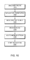
- FIG. 10 is a simplified method of detecting a failure and transferring replication between sites, in accordance with an embodiment of the present invention.
- FIG. 11 is an example of an embodiment of an apparatus that may utilize the techniques described herein, in accordance with an embodiment of the present invention.
- FIG. 12 is an example of an embodiment of a method embodied on a computer readable storage medium that may utilize the techniques described herein, in accordance with an embodiment of the present invention.
- journal based replication may be integrated with a virtual service layer.
- one or more splitters may be integrated into the virtual service layer.
- the virtual service lay may span multiple sites, and the sites may be at different geographic locations.
- each site may have one or more nodes and each node may have a splitter.
- the splitter may replicate the I/O.
- a splitter may mark the I/O without performing replication.
- there may be a protocol between the splitters in the virtual service layer.
- the protocol may enable the marked data to be cleared periodically for the splitter in the marking mode.
- replication at one site of the virtual service layer may failover to another site in the virtual service layer and replication may continue.
- the virtual service layer may enable replication and data protection at a local level, at a metropolitan level or distance, and at a geo or geographic distance.
- a metro distance may be considered one where data recorded at one site may be transmitted to a second site within a certain latency.
- a geo distance may be a distance where data transmitted between sites is greater than the aforementioned latency.
- BACKUP SITE may be a facility where replicated production site data is stored; the backup site may be located in a remote site or at the same location as the production site;
- DPA may be Data Protection Appliance a computer or a cluster of computers, or a set of processes that serve as a data protection appliance, responsible for data protection services including inter alia data replication of a storage system, and journaling of I/O requests issued by a host computer to the storage system;
- RPA may be replication protection appliance, is another name for DPA.
- HOST may be at least one computer or networks of computers that runs at least one data processing application that issues I/O requests to one or more storage systems; a host is an initiator with a SAN;
- HOST DEVICE may be an internal interface in a host, to a logical storage unit
- IMAGE may be a copy of a logical storage unit at a specific point in time
- INITIATOR may be a node in a SAN that issues I/O requests
- JOURNAL may be a record of write transactions issued to a storage system; used to maintain a duplicate storage system, and to rollback the duplicate storage system to a previous point in time;
- LOGICAL UNIT may be a logical entity provided by a storage system for accessing data from the storage system
- LUN may be a logical unit number for identifying a logical unit
- PHYSICAL STORAGE UNIT may be a physical entity, such as a disk or an array of disks, for storing data in storage locations that can be accessed by address;
- PRODUCTION SITE may be a facility where one or more host computers run data processing applications that write data to a storage system and read data from the storage system;
- SAN may be a storage area network of nodes that send and receive I/O and other requests, each node in the network being an initiator or a target, or both an initiator and a target;
- SOURCE SIDE may be a transmitter of data within a data replication workflow, during normal operation a production site is the source side; and during data recovery a backup site is the source side;
- Snapshot may refer to differential representations of an image, i.e. the snapshot may have pointers to the original volume, and may point to log volumes for changed locations. Snapshots may be combined into a snapshot array, which may represent different images over a time period.
- STORAGE SYSTEM may be a SAN entity that provides multiple logical units for access by multiple SAN initiators
- TARGET may be a node in a SAN that replies to I/O requests;
- SPLITTER/PROTECTION AGENT may be an agent running either on a production host a switch or a storage array which can intercept IO and split them to a DPA and to the storage array, fail IO redirect IO or do any other manipulation to the IO.
- VIRTUAL VOLUME may be a volume which is exposed to host by a virtualization layer, the virtual volume may be spanned across more than one site
- FAIL ALL MODE may be a mode of a volume in the splitter where all write and read IOs intercepted by the splitter are failed to the host, but other SCSI commands like read capacity are served.
- GLOBAL FAIL ALL MODE may be a mode of a volume in the virtual layer where all write and read IOs virtual layer are failed to the host, but other SCSI commands like read capacity are served.
- LOGGED ACCESS may be an access method provided by the appliance and the splitter, in which the appliance rolls the volumes of the consistency group to the point in time the user requested and let the host access the volumes in a copy on first write base.
- VIRTUAL ACCESS may be an access method provided by the appliance and the splitter, in which the appliance exposes a virtual volume from a specific point in time to the host, the data for the virtual volume is partially stored on the remote copy and partially stored on the journal.
- CDP Continuous Data Protection, may refer to a full replica of a volume or a set of volumes along with a journal which allows any point in time access, the CDP copy is at the same site, and maybe the same storage array of the production site
- Continuous Remote Replica may refer to a full replica of a volume or a set of volumes along with a journal which allows any point in time access at a site remote to the production volume and on a separate storage array.
- FIG. 1 is a simplified illustration of a data protection system 100 , in accordance with an embodiment of the present invention. Shown in FIG. 1 are two sites; Site I, which is a production site, on the right, and Site II, which is a backup site, on the left. Under normal operation the production site is the source side of system 100 , and the backup site is the target side of the system. The backup site is responsible for replicating production site data. Additionally, the backup site enables rollback of Site I data to an earlier pointing time, which may be used in the event of data corruption of a disaster, or alternatively in order to view or to access data from an earlier point in time.
- a failover may be performed in the event of a disaster at the production site, or for other reasons.
- Site I or Site II behaves as a production site for a portion of stored data, and behaves simultaneously as a backup site for another portion of stored data.
- a portion of stored data is replicated to a backup site, and another portion is not.
- the production site and the backup site may be remote from one another, or they may both be situated at a common site, local to one another.
- Local data protection has the advantage of minimizing data lag between target and source, and remote data protection has the advantage is being robust in the event that a disaster occurs at the source side.
- each side of system 100 includes three major components coupled via a storage area network (SAN); namely, (i) a storage system, (ii) a host computer, and (iii) a data protection appliance (DPA).
- SAN storage area network
- the source side SAN includes a source host computer 104 , a source storage system 108 , and a source DPA 112 .
- the target side SAN includes a target host computer 116 , a target storage system 120 , and a target DPA 124 .
- a SAN includes one or more devices, referred to as “nodes”.
- a node in a SAN may be an “initiator” or a “target”, or both.
- An initiator node is a device that is able to initiate requests to one or more other devices; and a target node is a device that is able to reply to requests, such as SCSI commands, sent by an initiator node.
- a SAN may also include network switches, such as fiber channel switches.
- the communication links between each host computer and its corresponding storage system may be any appropriate medium suitable for data transfer, such as fiber communication channel links.
- System 100 includes source storage system 108 and target storage system 120 .
- Each storage system includes physical storage units for storing data, such as disks or arrays of disks.
- storage systems 108 and 120 are target nodes.
- storage system 108 exposes one or more logical units (LU) to which commands are issued.
- LU logical units
- storage systems 108 and 120 are SAN entities that provide multiple logical units for access by multiple SAN initiators.
- Logical units are a logical entity provided by a storage system, for accessing data stored in the storage system.
- a logical unit is identified by a unique logical unit number (LUN).
- LUN unique logical unit number
- storage system 108 exposes a logical unit 136 , designated as LU A
- storage system 120 exposes a logical unit 156 , designated as LU B.
- LU B is used for replicating LU A. As such, LU B is generated as a copy of LU A. In one embodiment, LU B is configured so that its size is identical to the size of LU A. Thus for LU A, storage system 120 serves as a backup for source side storage system 108 . Alternatively, as mentioned hereinabove, some logical units of storage system 120 may be used to back up logical units of storage system 108 , and other logical units of storage system 120 may be used for other purposes.
- an operating system of a host computer creates a host device for each logical unit exposed by a storage system in the host computer SAN.
- a host device is a logical entity in a host computer, through which a host computer may access a logical unit.
- host device 104 identifies LU A and generates a corresponding host device 140 , designated as Device A, through which it can access LU A.
- host computer 116 identifies LU B and generates a corresponding device 160 , designated as Device B.
- System 100 includes two data protection appliances, a source side DPA 112 and a target side DPA 124 .
- a DPA performs various data protection services, such as data replication of a storage system, and journaling of I/O requests issued by a host computer to source side storage system data.
- data protection services such as data replication of a storage system, and journaling of I/O requests issued by a host computer to source side storage system data.
- a DPA may also enable rollback of data to an earlier point in time, and processing of rolled back data at the target site.
- Each DPA 112 and 124 is a computer that includes inter alia one or more conventional CPUs and internal memory.
- DPA 112 and DPA 124 are standalone devices integrated within a SAN.
- each of DPA 112 and DPA 124 may be integrated into storage system 108 and storage system 120 , respectively, or integrated into host computer 104 and host computer 116 , respectively.
- Both DPAs communicate with their respective host computers through communication lines such as fiber channels using, for example, SCSI commands.
- DPAs 112 and 124 are configured to act as initiators in the SAN; i.e., they can issue I/O requests using, for example, SCSI commands, to access logical units on their respective storage systems.
- DPA 112 and DPA 124 are also configured with the necessary functionality to act as targets; i.e., to reply to I/O requests, such as SCSI commands, issued by other initiators in the SAN, including inter alia their respective host computers 104 and 116 .
- targets i.e., to reply to I/O requests, such as SCSI commands, issued by other initiators in the SAN, including inter alia their respective host computers 104 and 116 .
- DPA 112 and DPA 124 may dynamically expose or remove one or more logical units.
- Site I and Site II may each behave simultaneously as a production site and a backup site for different logical units.
- DPA 112 and DPA 124 may each behave as a source DPA for some logical units, and as a target DPA for other logical units, at the same time.
- host computer 104 and host computer 116 include protection agents 144 and 164 , respectively.
- Protection agents 144 and 164 intercept SCSI commands issued by their respective host computers, via host devices to logical units that are accessible to the host computers.
- a data protection agent may act on an intercepted SCSI commands issued to a logical unit, in one of the following ways:
- a protection agent may handle different SCSI commands, differently, according to the type of the command. For example, a SCSI command inquiring about the size of a certain logical unit may be sent directly to that logical unit, while a SCSI write command may be split and sent first to a DPA associated with the agent.
- a protection agent may also change its behavior for handling SCSI commands, for example as a result of an instruction received from the DPA.
- the behavior of a protection agent for a certain host device generally corresponds to the behavior of its associated DPA with respect to the logical unit of the host device.
- the associated protection agent splits I/O requests issued by a host computer to the host device corresponding to that logical unit.
- the associated protection agent fails I/O requests issued by host computer to the host device corresponding to that logical unit.
- Protection agents may use any protocol suitable for data transfer within a SAN, such as fiber channel, or SCSI over fiber channel.
- the communication may be direct, or via a logical unit exposed by the DPA.
- protection agents communicate with their respective DPAs by sending SCSI commands over fiber channel.
- DPA 112 acts as a source site DPA for LU A.
- protection agent 144 is configured to act as a source side protection agent; i.e., as a splitter for host device A.
- protection agent 144 replicates SCSI I/O requests.
- a replicated SCSI I/O request is sent to DPA 112 .
- protection agent 144 After receiving an acknowledgement from DPA 124 , protection agent 144 then sends the SCSI I/O request to LU A. Only after receiving a second acknowledgement from storage system 108 may host computer 104 initiate another I/O request.
- DPA 112 When DPA 112 receives a replicated SCSI write request from data protection agent 144 , DPA 112 transmits certain I/O information characterizing the write request, packaged as a “write transaction”, over WAN 128 to DPA 124 on the target side, for journaling and for incorporation within target storage system 120 .
- DPA 112 may send its write transactions to DPA 124 using a variety of modes of transmission, including inter alia (i) a synchronous mode, (ii) an asynchronous mode, and (iii) a snapshot mode.
- DPA 112 sends each write transaction to DPA 124 , receives back an acknowledgement from DPA 124 , and in turns sends an acknowledgement back to protection agent 144 .
- Protection agent 144 waits until receipt of such acknowledgement before sending the SCSI write request to LU A.
- DPA 124 While in production mode, DPA 124 receives replicated data of LU A from DPA 112 , and performs journaling and writing to storage system 120 . When applying write operations to storage system 120 , DPA 124 acts as an initiator, and sends SCSI commands to LU B.
- DPA 124 undoes the write transactions in the journal, so as to restore storage system 120 to the state it was at, at an earlier time.
- LU B is used as a backup of LU A.
- host computer 116 should not be sending I/O requests to LU B.
- protection agent 164 acts as a target site protection agent for host Device B and fails I/O requests sent from host computer 116 to LU B through host Device B.
- target storage system 120 exposes a logical unit 176 , referred to as a “journal LU”, for maintaining a history of write transactions made to LU B, referred to as a “journal”.
- journal LU 176 may be striped over several logical units, or may reside within all of or a portion of another logical unit.
- DPA 124 includes a journal processor 180 for managing the journal.
- Journal processor 180 functions generally to manage the journal entries of LU B. Specifically, journal processor 180 ( i ) enters write transactions received by DPA 124 from DPA 112 into the journal, by writing them into the journal LU, (ii) applies the journal transactions to LU B, and (iii) updates the journal entries in the journal LU with undo information and removes already-applied transactions from the journal. As described below, with reference to FIGS. 2 and 3A-3D , journal entries include four streams, two of which are written when write transaction are entered into the journal, and two of which are written when write transaction are applied and removed from the journal.
- Write transaction 200 generally includes the following fields:
- a third stream referred to as an UNDO stream
- a fourth stream referred to as an UNDO METADATA
- an identifier a date & time
- a write size a beginning address in LU B where data was to be overwritten
- the journal LU is partitioned into segments with a pre-defined size, such as 1 MB segments, with each segment identified by a counter.
- the collection of such segments forms a segment pool for the four journaling streams described hereinabove.
- Each such stream is structured as an ordered list of segments, into which the stream data is written, and includes two pointers—a beginning pointer that points to the first segment in the list and an end pointer that points to the last segment in the list.
- DO data is written into the DO stream, and the pointer to the appropriate first or last segment is updated. Freeing of segments in the ordered list is performed by simply changing the beginning or the end pointer. Freed segments are returned to the segment pool for re-use.
- a delta marker stream may contain the locations that may be different between the latest I/O data which arrived to the remote side (the current remote site) and the latest I/O data which arrived at the local side.
- the delta marking stream may include metadata of the differences between the source side and the target side. For example, every I/O reaching the data protection appliance for the source 112 may be written to the delta marking stream and data is freed from the delta marking stream when the data safely arrives at both the source volume of replication 108 and the remote journal 180 (e.g. DO stream). Specifically, during an initialization process no data may be freed from the delta marking stream; and only when the initialization process is completed and I/O data has arrived to both local storage and the remote journal data, may be I/O data from the delta marking stream freed.
- the virtual service layer enables cache coherency.
- the storage volumes, in a virtualized server environment, which comprise the encapsulation of a virtual machine may be coherently co-located in two sites, enabling simultaneous, local access by the virtual machine regardless of whether the virtual machine is located on the local or remote site.
- concurrent read and write access to data by multiple hosts across two locations may be enabled.
- realtime data access to remote physical data centers without local storage may be enabled.
- the virtual service layer may be implemented by EMC's VPLEX or the like.
- replication and data mobility may be enabled at difference geographic sites. In certain embodiments, this may be enabled by cache coherency functionality. In at least some embodiments, the cache coherency may enable data to be consistent over large distances and be able to be accessed at both geo sites. In a particular embodiment, there may be two geo sites. In this embodiment, if a read is performed on an area of the storage that does not belong to the local site, the read may be delayed and the read may be performed on the remote site. In this embodiment, if a read is performed on an area owned by the local site, then the read may be performed on the local site.
- a virtual service layer may have journal based replication.
- data consistency between different sites serviced by a virtual service layer may be ensured.
- one or more splitter may be integrated into the virtual service layer.
- an I/O splitter has been inserted into the Virtual Service Layer.
- the splitter 427 may split I/O occurring at the virtual service layer 485 .
- the I/O Splitter may be made up of one or more splitters in each node at each site. In the example embodiment of FIG. 4 , there is one node at each site 410 and 450 and there is one splitter 428 , 429 , respectively, for each site 410 , 450 .
- FIG. 5 illustrates a sample virtual service layer divided into underlying layers.
- the Virtual Service Layer 510 has a front-end SCSI target 515 that may be exposed to a host.
- the cache may be a write-through cache. In other embodiments it may be a write-order fidelity cache.
- FIG. 5 there is also a virtual volume 530 also exposed to a host or several hosts.
- the virtual volume may be supported by a distributed mirror 540 .
- a distributed mirror may be a mirror which gives a remote active copy of the volume that is mirrored at another site.
- the distributed mirror enables mirroring between two geographically disparate sites.
- splitter 615 communicates with recovery appliance 625 .
- the appliance may alternatively be set of process running inside the virtual service cluster.
- Splitter 615 splits the I/O in the virtual service layer and sends the I/O to recovery appliance 625 and to the block virtualization layer.
- the recovery appliance 625 may keep journal 640 of the I/O and may also keep a repository volume 645 , for persistent configuration, and may keep a copy of the production image 635 serviced by the Virtual service layer 610 , the appliance may also transfer the data to a remote site and create a remote copy of the data in a different storage array.
- sites 710 and 720 have virtual service layers 715 , 725 and each VSL has a splitter, 730 , and 735 .
- the Virtual Volumes or production volumes 750 and 752 are distributed mirrors and kept consistent across sites 710 , 720 .
- Each IO performed at site 710 may be transmitted to site 720 .
- both splitters, 730 , 735 may intercept the same I/O and the same I/O may be intercepted twice.
- directors 727 and 728 there may be multiple directors such as directors 727 and 728 .
- a director may be a construct that exposes the LUNs in the storage. Two directors may form a construct called an engine.
- Each director 727 , 728 in VSL 715 may have a splitter 730 , 731 . All the directors at each site may expose the LUNs to hosts, the host may send each IO to one of the directors (for load balancing IOs to the same LUN may be sent to different directors), the IO arriving at a director may be intercepted by the splitter running at the same director, if the volume is a distributed mirror, the IO may also be sent to another director at the mirror site and intercepted also by the splitter running at the other director.
- each recovery appliance at each site may have a protocol to decide which recovery appliance is the lead recovery appliance and the lead recovery appliance splits the I/O, for each replicated volume or replicated consistency group.
- this protocol may enable a second recovery appliance to realize when another site has failed and take over replication for the failed site.
- Site 810 fails, the virtual layer continues serving IOs on site 820 , and splitter 835 may continue to track the changes.
- the failure of site 810 is discovered (step 1010 ).
- the discovery protocol may be done in a similar way to that discussed in U.S. Pat. No. 7,840,662 entitled “DYNAMICALLY MANAGING A NETWORK CLUSTER,” issued on Nov. 23, 2010 to EMC Corp, which is hereby incorporated by reference.
- the RPA cluster is a split cluster and all resources such as journal repository and replica volume are available, since the resources are distributed volumes, thus replication may continue immediately.
- the replication cluster management tells appliance 846 to take control of replicating production volume 852 and all other volumes in its consistency group (step 1020 ).
- Appliance 846 notifies splitter 835 to start splitting IOs to appliance 846 (step 1030 ).
- the appliance reads the last elements which remained in the marking metadata area of splitter and begins replication 835 (step 1040 ).
- the marking area is not freed due to the failure of site 810 , since the free protocol may be managed by splitter 830 .
- the data flushed to the journal is available at site 820 .
- the backlog containing all the meta data tracked and not freed in the memory of splitter 835 is read from the splitter 835 and added to the marking stream ( 1045 ), the marking stream contains the meta data of the data which may now arrived to the CDP and CRR copies. Replication is resumed to both CDP and CRR copy, only latest changes may need to be resynched (step 1050 )
- site 810 When site 810 recovers site 810 may start tracking data in MOH mode, when site 810 returns, it may have data dirty in its memory backlog. If site 810 crashes again before one phase of the free protocol is performed, such as the method of FIG. 9 , there may be a need to do a complete sweep, if replication is moved to this site. After the first free protocol completes, the memory backlog may only include the latest transactions.
- the logic for carrying out the method may be embodied as part of the aforementioned system, which is useful for carrying out a method described with reference to embodiments shown in, for example, FIG. 1 and FIG. 2 .
- the invention is described as embodied in a specific configuration and using special logical arrangements, but one skilled in the art may appreciate that the device is not limited to the specific configuration but rather only by the claims included with this specification.
Abstract
Description
Claims (20)
Priority Applications (1)
| Application Number | Priority Date | Filing Date | Title |
|---|---|---|---|
| US14/744,565 US9811431B1 (en) | 2011-03-31 | 2015-06-19 | Networked based replication of distributed volumes |
Applications Claiming Priority (2)
| Application Number | Priority Date | Filing Date | Title |
|---|---|---|---|
| US13/077,266 US9063994B1 (en) | 2011-03-31 | 2011-03-31 | Networked based replication of distributed volumes |
| US14/744,565 US9811431B1 (en) | 2011-03-31 | 2015-06-19 | Networked based replication of distributed volumes |
Related Parent Applications (1)
| Application Number | Title | Priority Date | Filing Date |
|---|---|---|---|
| US13/077,266 Continuation US9063994B1 (en) | 2011-03-31 | 2011-03-31 | Networked based replication of distributed volumes |
Publications (1)
| Publication Number | Publication Date |
|---|---|
| US9811431B1 true US9811431B1 (en) | 2017-11-07 |
Family
ID=53397145
Family Applications (2)
| Application Number | Title | Priority Date | Filing Date |
|---|---|---|---|
| US13/077,266 Active US9063994B1 (en) | 2011-03-31 | 2011-03-31 | Networked based replication of distributed volumes |
| US14/744,565 Active US9811431B1 (en) | 2011-03-31 | 2015-06-19 | Networked based replication of distributed volumes |
Family Applications Before (1)
| Application Number | Title | Priority Date | Filing Date |
|---|---|---|---|
| US13/077,266 Active US9063994B1 (en) | 2011-03-31 | 2011-03-31 | Networked based replication of distributed volumes |
Country Status (1)
| Country | Link |
|---|---|
| US (2) | US9063994B1 (en) |
Cited By (61)
| Publication number | Priority date | Publication date | Assignee | Title |
|---|---|---|---|---|
| US20160196183A1 (en) * | 2015-01-04 | 2016-07-07 | Emc Corporation | Providing access to resources |
| US9959061B1 (en) * | 2015-09-30 | 2018-05-01 | EMC IP Holding Company LLC | Data synchronization |
| CN108255643A (en) * | 2017-12-25 | 2018-07-06 | 南京壹进制信息技术股份有限公司 | A kind of continuous data protection method of no agency |
| US10019194B1 (en) | 2016-09-23 | 2018-07-10 | EMC IP Holding Company LLC | Eventually consistent synchronous data replication in a storage system |
| US10031703B1 (en) | 2013-12-31 | 2018-07-24 | Emc Corporation | Extent-based tiering for virtual storage using full LUNs |
| US10042751B1 (en) | 2015-09-30 | 2018-08-07 | EMC IP Holding Company LLC | Method and system for multi-tier all-flash array |
| US10055148B1 (en) | 2015-12-22 | 2018-08-21 | EMC IP Holding Company LLC | Storing application data as an enhanced copy |
| US10061666B1 (en) | 2011-12-30 | 2018-08-28 | Emc International Company | Method and apparatus for adding a director to storage with network-based replication without data resynchronization |
| US10067837B1 (en) | 2015-12-28 | 2018-09-04 | EMC IP Holding Company LLC | Continuous data protection with cloud resources |
| US10078459B1 (en) | 2016-09-26 | 2018-09-18 | EMC IP Holding Company LLC | Ransomware detection using I/O patterns |
| US10082980B1 (en) | 2014-06-20 | 2018-09-25 | EMC IP Holding Company LLC | Migration of snapshot in replication system using a log |
| US10101943B1 (en) | 2014-09-25 | 2018-10-16 | EMC IP Holding Company LLC | Realigning data in replication system |
| US10108356B1 (en) | 2016-03-25 | 2018-10-23 | EMC IP Holding Company LLC | Determining data to store in retention storage |
| US10114581B1 (en) | 2016-12-27 | 2018-10-30 | EMC IP Holding Company LLC | Creating a virtual access point in time on an object based journal replication |
| US10133874B1 (en) | 2015-12-28 | 2018-11-20 | EMC IP Holding Company LLC | Performing snapshot replication on a storage system not configured to support snapshot replication |
| US10133593B1 (en) * | 2016-03-31 | 2018-11-20 | Amazon Technologies, Inc. | Virtual machine migration |
| US10140039B1 (en) | 2016-12-15 | 2018-11-27 | EMC IP Holding Company LLC | I/O alignment for continuous replication in a storage system |
| US10146961B1 (en) | 2016-09-23 | 2018-12-04 | EMC IP Holding Company LLC | Encrypting replication journals in a storage system |
| US10152267B1 (en) | 2016-03-30 | 2018-12-11 | Emc Corporation | Replication data pull |
| CN109274537A (en) * | 2018-10-25 | 2019-01-25 | 深圳供电局有限公司 | A kind of continuity network virtualization platform system |
| US10191687B1 (en) | 2016-12-15 | 2019-01-29 | EMC IP Holding Company LLC | Adaptive snap-based replication in a storage system |
| US10210073B1 (en) | 2016-09-23 | 2019-02-19 | EMC IP Holding Company, LLC | Real time debugging of production replicated data with data obfuscation in a storage system |
| US10223023B1 (en) | 2016-09-26 | 2019-03-05 | EMC IP Holding Company LLC | Bandwidth reduction for multi-level data replication |
| US10229006B1 (en) | 2015-12-28 | 2019-03-12 | EMC IP Holding Company LLC | Providing continuous data protection on a storage array configured to generate snapshots |
| US10235196B1 (en) | 2015-12-28 | 2019-03-19 | EMC IP Holding Company LLC | Virtual machine joining or separating |
| US10235247B1 (en) | 2016-09-26 | 2019-03-19 | EMC IP Holding Company LLC | Compressing memory snapshots |
| US10235087B1 (en) | 2016-03-30 | 2019-03-19 | EMC IP Holding Company LLC | Distributing journal data over multiple journals |
| US10235061B1 (en) | 2016-09-26 | 2019-03-19 | EMC IP Holding Company LLC | Granular virtual machine snapshots |
| US10235091B1 (en) | 2016-09-23 | 2019-03-19 | EMC IP Holding Company LLC | Full sweep disk synchronization in a storage system |
| US10235088B1 (en) | 2016-03-30 | 2019-03-19 | EMC IP Holding Company LLC | Global replication policy for multi-copy replication |
| US10235090B1 (en) | 2016-09-23 | 2019-03-19 | EMC IP Holding Company LLC | Validating replication copy consistency using a hash function in a storage system |
| US10235145B1 (en) | 2012-09-13 | 2019-03-19 | Emc International Company | Distributed scale-out replication |
| US10235064B1 (en) | 2016-12-27 | 2019-03-19 | EMC IP Holding Company LLC | Optimized data replication using special NVME protocol and running in a friendly zone of storage array |
| US10235060B1 (en) | 2016-04-14 | 2019-03-19 | EMC IP Holding Company, LLC | Multilevel snapshot replication for hot and cold regions of a storage system |
| US10235092B1 (en) | 2016-12-15 | 2019-03-19 | EMC IP Holding Company LLC | Independent parallel on demand recovery of data replicas in a storage system |
| CN109714394A (en) * | 2018-12-05 | 2019-05-03 | 深圳店匠科技有限公司 | Information synchronization method, system and the storage medium of cross-border more server-sides |
| US10296419B1 (en) | 2015-03-27 | 2019-05-21 | EMC IP Holding Company LLC | Accessing a virtual device using a kernel |
| US10324637B1 (en) | 2016-12-13 | 2019-06-18 | EMC IP Holding Company LLC | Dual-splitter for high performance replication |
| US10324798B1 (en) | 2014-09-25 | 2019-06-18 | EMC IP Holding Company LLC | Restoring active areas of a logical unit |
| US10353603B1 (en) | 2016-12-27 | 2019-07-16 | EMC IP Holding Company LLC | Storage container based replication services |
| US10366011B1 (en) | 2018-05-03 | 2019-07-30 | EMC IP Holding Company LLC | Content-based deduplicated storage having multilevel data cache |
| US10409986B1 (en) | 2016-09-26 | 2019-09-10 | EMC IP Holding Company LLC | Ransomware detection in a continuous data protection environment |
| US10409787B1 (en) | 2015-12-22 | 2019-09-10 | EMC IP Holding Company LLC | Database migration |
| US10409629B1 (en) | 2016-09-26 | 2019-09-10 | EMC IP Holding Company LLC | Automated host data protection configuration |
| US10423634B1 (en) | 2016-12-27 | 2019-09-24 | EMC IP Holding Company LLC | Temporal queries on secondary storage |
| US10437783B1 (en) | 2014-09-25 | 2019-10-08 | EMC IP Holding Company LLC | Recover storage array using remote deduplication device |
| US10467102B1 (en) | 2016-12-15 | 2019-11-05 | EMC IP Holding Company LLC | I/O score-based hybrid replication in a storage system |
| US10489321B1 (en) | 2018-07-31 | 2019-11-26 | EMC IP Holding Company LLC | Performance improvement for an active-active distributed non-ALUA system with address ownerships |
| US10496487B1 (en) | 2014-12-03 | 2019-12-03 | EMC IP Holding Company LLC | Storing snapshot changes with snapshots |
| US10579282B1 (en) | 2016-03-30 | 2020-03-03 | EMC IP Holding Company LLC | Distributed copy in multi-copy replication where offset and size of I/O requests to replication site is half offset and size of I/O request to production volume |
| US10592166B2 (en) | 2018-08-01 | 2020-03-17 | EMC IP Holding Company LLC | Fast input/output in a content-addressable storage architecture with paged metadata |
| US10628268B1 (en) | 2016-12-15 | 2020-04-21 | EMC IP Holding Company LLC | Proof of data replication consistency using blockchain |
| US10713221B2 (en) | 2018-07-30 | 2020-07-14 | EMC IP Holding Company LLC | Dual layer deduplication for a file system running over a deduplicated block storage |
| US10747667B2 (en) | 2018-11-02 | 2020-08-18 | EMC IP Holding Company LLC | Memory management of multi-level metadata cache for content-based deduplicated storage |
| US10747606B1 (en) | 2016-12-21 | 2020-08-18 | EMC IP Holding Company LLC | Risk based analysis of adverse event impact on system availability |
| US10776211B1 (en) | 2016-12-27 | 2020-09-15 | EMC IP Holding Company LLC | Methods, systems, and apparatuses to update point in time journal using map reduce to create a highly parallel update |
| US10853181B1 (en) | 2015-06-29 | 2020-12-01 | EMC IP Holding Company LLC | Backing up volumes using fragment files |
| US11010409B1 (en) * | 2016-03-29 | 2021-05-18 | EMC IP Holding Company LLC | Multi-streaming with synthetic replication |
| US11044324B2 (en) | 2017-04-17 | 2021-06-22 | EMC IP Holding Company LLC | Method and device for maintaining session of network storage device |
| US11093158B2 (en) | 2019-01-29 | 2021-08-17 | EMC IP Holding Company LLC | Sub-lun non-deduplicated tier in a CAS storage to reduce mapping information and improve memory efficiency |
| US11386043B2 (en) | 2019-07-30 | 2022-07-12 | EMC IP Holding Company LLC | Method, device, and computer program product for managing snapshot in application environment |
Families Citing this family (39)
| Publication number | Priority date | Publication date | Assignee | Title |
|---|---|---|---|---|
| US9501542B1 (en) | 2008-03-11 | 2016-11-22 | Emc Corporation | Methods and apparatus for volume synchronization |
| US9256605B1 (en) | 2011-08-03 | 2016-02-09 | Emc Corporation | Reading and writing to an unexposed device |
| US9286052B1 (en) | 2011-09-15 | 2016-03-15 | Emc Corporation | Upgrading software on a pair of nodes in a clustered environment |
| US9223659B1 (en) | 2012-06-28 | 2015-12-29 | Emc International Company | Generating and accessing a virtual volume snapshot in a continuous data protection system |
| US9336094B1 (en) | 2012-09-13 | 2016-05-10 | Emc International Company | Scaleout replication of an application |
| US9696939B1 (en) | 2013-03-14 | 2017-07-04 | EMC IP Holding Company LLC | Replicating data using deduplication-based arrays using network-based replication |
| US9383937B1 (en) | 2013-03-14 | 2016-07-05 | Emc Corporation | Journal tiering in a continuous data protection system using deduplication-based storage |
| US9244997B1 (en) | 2013-03-15 | 2016-01-26 | Emc Corporation | Asymmetric active-active access of asynchronously-protected data storage |
| US9367260B1 (en) | 2013-12-13 | 2016-06-14 | Emc Corporation | Dynamic replication system |
| US9405765B1 (en) | 2013-12-17 | 2016-08-02 | Emc Corporation | Replication of virtual machines |
| US9460182B2 (en) * | 2014-03-20 | 2016-10-04 | International Business Machines Corporation | Networking-assisted input/output order preservation for data replication |
| US9189339B1 (en) | 2014-03-28 | 2015-11-17 | Emc Corporation | Replication of a virtual distributed volume with virtual machine granualarity |
| US9274718B1 (en) | 2014-06-20 | 2016-03-01 | Emc Corporation | Migration in replication system |
| US9619543B1 (en) | 2014-06-23 | 2017-04-11 | EMC IP Holding Company LLC | Replicating in virtual desktop infrastructure |
| US9218407B1 (en) | 2014-06-25 | 2015-12-22 | Pure Storage, Inc. | Replication and intermediate read-write state for mediums |
| US9910621B1 (en) | 2014-09-29 | 2018-03-06 | EMC IP Holding Company LLC | Backlogging I/O metadata utilizing counters to monitor write acknowledgements and no acknowledgements |
| US9529885B1 (en) | 2014-09-29 | 2016-12-27 | EMC IP Holding Company LLC | Maintaining consistent point-in-time in asynchronous replication during virtual machine relocation |
| US9600377B1 (en) | 2014-12-03 | 2017-03-21 | EMC IP Holding Company LLC | Providing data protection using point-in-time images from multiple types of storage devices |
| US9405481B1 (en) | 2014-12-17 | 2016-08-02 | Emc Corporation | Replicating using volume multiplexing with consistency group file |
| US9632881B1 (en) | 2015-03-24 | 2017-04-25 | EMC IP Holding Company LLC | Replication of a virtual distributed volume |
| US9557921B1 (en) | 2015-03-26 | 2017-01-31 | EMC IP Holding Company LLC | Virtual volume converter |
| US9411535B1 (en) | 2015-03-27 | 2016-08-09 | Emc Corporation | Accessing multiple virtual devices |
| US9678680B1 (en) | 2015-03-30 | 2017-06-13 | EMC IP Holding Company LLC | Forming a protection domain in a storage architecture |
| US9875042B1 (en) * | 2015-03-31 | 2018-01-23 | EMC IP Holding Company LLC | Asynchronous replication |
| US9826030B1 (en) * | 2015-06-04 | 2017-11-21 | Amazon Technologies, Inc. | Placement of volume partition replica pairs |
| US9826041B1 (en) | 2015-06-04 | 2017-11-21 | Amazon Technologies, Inc. | Relative placement of volume partitions |
| US9665305B1 (en) | 2015-06-26 | 2017-05-30 | EMC IP Holding Company LLC | Tiering data between two deduplication devices |
| US9817729B2 (en) * | 2015-07-30 | 2017-11-14 | Zerto Ltd. | Method for restoring files from a continuous recovery system |
| US9778865B1 (en) * | 2015-09-08 | 2017-10-03 | EMC IP Holding Company LLC | Hyper-converged infrastructure based on server pairs |
| US9830082B1 (en) | 2015-09-08 | 2017-11-28 | EMC IP Holding Company LLC | Hybrid hyper-converged infrastructure and storage appliance |
| US9684576B1 (en) | 2015-12-21 | 2017-06-20 | EMC IP Holding Company LLC | Replication using a virtual distributed volume |
| US9910735B1 (en) | 2016-03-30 | 2018-03-06 | EMC IP Holding Company LLC | Generating an application-consistent snapshot |
| US10802919B1 (en) * | 2016-12-30 | 2020-10-13 | EMC IP Holding Company LLC | Methods and apparatus for consistency group replication with reduced resource consumption |
| US20180309826A1 (en) * | 2017-04-24 | 2018-10-25 | EITR Systems, Inc. | Fault-tolerant storage system using an alternate network |
| US10606802B2 (en) | 2017-05-15 | 2020-03-31 | International Business Machines Corporation | Catalog backup and recovery using logical mirroring |
| US10977274B2 (en) | 2017-10-05 | 2021-04-13 | Sungard Availability Services, Lp | Unified replication and recovery |
| US10474545B1 (en) * | 2017-10-31 | 2019-11-12 | EMC IP Holding Company LLC | Storage system with distributed input-output sequencing |
| US10365980B1 (en) * | 2017-10-31 | 2019-07-30 | EMC IP Holding Company LLC | Storage system with selectable cached and cacheless modes of operation for distributed storage virtualization |
| US11733874B2 (en) * | 2021-05-03 | 2023-08-22 | EMC IP Holding Company LLC | Managing replication journal in a distributed replication system |
Citations (2)
| Publication number | Priority date | Publication date | Assignee | Title |
|---|---|---|---|---|
| US5435004A (en) * | 1994-07-21 | 1995-07-18 | International Business Machines Corporation | Computerized system and method for data backup |
| US20100050013A1 (en) * | 2003-08-14 | 2010-02-25 | Soran Philip E | Virtual disk drive system and method |
Family Cites Families (2)
| Publication number | Priority date | Publication date | Assignee | Title |
|---|---|---|---|---|
| US7302500B2 (en) * | 2003-04-30 | 2007-11-27 | Dynamic Network Factory, Inc. | Apparatus and method for packet based storage virtualization |
| EP1962192A1 (en) * | 2007-02-21 | 2008-08-27 | Deutsche Telekom AG | Method and system for the transparent migration of virtual machine storage |
-
2011
- 2011-03-31 US US13/077,266 patent/US9063994B1/en active Active
-
2015
- 2015-06-19 US US14/744,565 patent/US9811431B1/en active Active
Patent Citations (2)
| Publication number | Priority date | Publication date | Assignee | Title |
|---|---|---|---|---|
| US5435004A (en) * | 1994-07-21 | 1995-07-18 | International Business Machines Corporation | Computerized system and method for data backup |
| US20100050013A1 (en) * | 2003-08-14 | 2010-02-25 | Soran Philip E | Virtual disk drive system and method |
Cited By (67)
| Publication number | Priority date | Publication date | Assignee | Title |
|---|---|---|---|---|
| US10061666B1 (en) | 2011-12-30 | 2018-08-28 | Emc International Company | Method and apparatus for adding a director to storage with network-based replication without data resynchronization |
| US10235145B1 (en) | 2012-09-13 | 2019-03-19 | Emc International Company | Distributed scale-out replication |
| US10031703B1 (en) | 2013-12-31 | 2018-07-24 | Emc Corporation | Extent-based tiering for virtual storage using full LUNs |
| US10082980B1 (en) | 2014-06-20 | 2018-09-25 | EMC IP Holding Company LLC | Migration of snapshot in replication system using a log |
| US10324798B1 (en) | 2014-09-25 | 2019-06-18 | EMC IP Holding Company LLC | Restoring active areas of a logical unit |
| US10101943B1 (en) | 2014-09-25 | 2018-10-16 | EMC IP Holding Company LLC | Realigning data in replication system |
| US10437783B1 (en) | 2014-09-25 | 2019-10-08 | EMC IP Holding Company LLC | Recover storage array using remote deduplication device |
| US10496487B1 (en) | 2014-12-03 | 2019-12-03 | EMC IP Holding Company LLC | Storing snapshot changes with snapshots |
| US10789214B2 (en) * | 2015-01-04 | 2020-09-29 | EMC IP Holding Company LLC | Providing access to resources |
| US20160196183A1 (en) * | 2015-01-04 | 2016-07-07 | Emc Corporation | Providing access to resources |
| US10296419B1 (en) | 2015-03-27 | 2019-05-21 | EMC IP Holding Company LLC | Accessing a virtual device using a kernel |
| US10853181B1 (en) | 2015-06-29 | 2020-12-01 | EMC IP Holding Company LLC | Backing up volumes using fragment files |
| US10042751B1 (en) | 2015-09-30 | 2018-08-07 | EMC IP Holding Company LLC | Method and system for multi-tier all-flash array |
| US9959061B1 (en) * | 2015-09-30 | 2018-05-01 | EMC IP Holding Company LLC | Data synchronization |
| US10055148B1 (en) | 2015-12-22 | 2018-08-21 | EMC IP Holding Company LLC | Storing application data as an enhanced copy |
| US10409787B1 (en) | 2015-12-22 | 2019-09-10 | EMC IP Holding Company LLC | Database migration |
| US10067837B1 (en) | 2015-12-28 | 2018-09-04 | EMC IP Holding Company LLC | Continuous data protection with cloud resources |
| US10133874B1 (en) | 2015-12-28 | 2018-11-20 | EMC IP Holding Company LLC | Performing snapshot replication on a storage system not configured to support snapshot replication |
| US10235196B1 (en) | 2015-12-28 | 2019-03-19 | EMC IP Holding Company LLC | Virtual machine joining or separating |
| US10229006B1 (en) | 2015-12-28 | 2019-03-12 | EMC IP Holding Company LLC | Providing continuous data protection on a storage array configured to generate snapshots |
| US10108356B1 (en) | 2016-03-25 | 2018-10-23 | EMC IP Holding Company LLC | Determining data to store in retention storage |
| US11010409B1 (en) * | 2016-03-29 | 2021-05-18 | EMC IP Holding Company LLC | Multi-streaming with synthetic replication |
| US10235088B1 (en) | 2016-03-30 | 2019-03-19 | EMC IP Holding Company LLC | Global replication policy for multi-copy replication |
| US10152267B1 (en) | 2016-03-30 | 2018-12-11 | Emc Corporation | Replication data pull |
| US10579282B1 (en) | 2016-03-30 | 2020-03-03 | EMC IP Holding Company LLC | Distributed copy in multi-copy replication where offset and size of I/O requests to replication site is half offset and size of I/O request to production volume |
| US10235087B1 (en) | 2016-03-30 | 2019-03-19 | EMC IP Holding Company LLC | Distributing journal data over multiple journals |
| US10133593B1 (en) * | 2016-03-31 | 2018-11-20 | Amazon Technologies, Inc. | Virtual machine migration |
| US10698721B2 (en) | 2016-03-31 | 2020-06-30 | Amazon Technologies, Inc. | Virtual machine migration |
| US10235060B1 (en) | 2016-04-14 | 2019-03-19 | EMC IP Holding Company, LLC | Multilevel snapshot replication for hot and cold regions of a storage system |
| US10019194B1 (en) | 2016-09-23 | 2018-07-10 | EMC IP Holding Company LLC | Eventually consistent synchronous data replication in a storage system |
| US10235090B1 (en) | 2016-09-23 | 2019-03-19 | EMC IP Holding Company LLC | Validating replication copy consistency using a hash function in a storage system |
| US10146961B1 (en) | 2016-09-23 | 2018-12-04 | EMC IP Holding Company LLC | Encrypting replication journals in a storage system |
| US10235091B1 (en) | 2016-09-23 | 2019-03-19 | EMC IP Holding Company LLC | Full sweep disk synchronization in a storage system |
| US10210073B1 (en) | 2016-09-23 | 2019-02-19 | EMC IP Holding Company, LLC | Real time debugging of production replicated data with data obfuscation in a storage system |
| US10409986B1 (en) | 2016-09-26 | 2019-09-10 | EMC IP Holding Company LLC | Ransomware detection in a continuous data protection environment |
| US10235061B1 (en) | 2016-09-26 | 2019-03-19 | EMC IP Holding Company LLC | Granular virtual machine snapshots |
| US10223023B1 (en) | 2016-09-26 | 2019-03-05 | EMC IP Holding Company LLC | Bandwidth reduction for multi-level data replication |
| US10409629B1 (en) | 2016-09-26 | 2019-09-10 | EMC IP Holding Company LLC | Automated host data protection configuration |
| US10235247B1 (en) | 2016-09-26 | 2019-03-19 | EMC IP Holding Company LLC | Compressing memory snapshots |
| US10078459B1 (en) | 2016-09-26 | 2018-09-18 | EMC IP Holding Company LLC | Ransomware detection using I/O patterns |
| US11016677B2 (en) | 2016-12-13 | 2021-05-25 | EMC IP Holding Company LLC | Dual-splitter for high performance replication |
| US10324637B1 (en) | 2016-12-13 | 2019-06-18 | EMC IP Holding Company LLC | Dual-splitter for high performance replication |
| US10235092B1 (en) | 2016-12-15 | 2019-03-19 | EMC IP Holding Company LLC | Independent parallel on demand recovery of data replicas in a storage system |
| US10191687B1 (en) | 2016-12-15 | 2019-01-29 | EMC IP Holding Company LLC | Adaptive snap-based replication in a storage system |
| US10628268B1 (en) | 2016-12-15 | 2020-04-21 | EMC IP Holding Company LLC | Proof of data replication consistency using blockchain |
| US10467102B1 (en) | 2016-12-15 | 2019-11-05 | EMC IP Holding Company LLC | I/O score-based hybrid replication in a storage system |
| US10140039B1 (en) | 2016-12-15 | 2018-11-27 | EMC IP Holding Company LLC | I/O alignment for continuous replication in a storage system |
| US10747606B1 (en) | 2016-12-21 | 2020-08-18 | EMC IP Holding Company LLC | Risk based analysis of adverse event impact on system availability |
| US10776211B1 (en) | 2016-12-27 | 2020-09-15 | EMC IP Holding Company LLC | Methods, systems, and apparatuses to update point in time journal using map reduce to create a highly parallel update |
| US10235064B1 (en) | 2016-12-27 | 2019-03-19 | EMC IP Holding Company LLC | Optimized data replication using special NVME protocol and running in a friendly zone of storage array |
| US10353603B1 (en) | 2016-12-27 | 2019-07-16 | EMC IP Holding Company LLC | Storage container based replication services |
| US10423634B1 (en) | 2016-12-27 | 2019-09-24 | EMC IP Holding Company LLC | Temporal queries on secondary storage |
| US10114581B1 (en) | 2016-12-27 | 2018-10-30 | EMC IP Holding Company LLC | Creating a virtual access point in time on an object based journal replication |
| US11044324B2 (en) | 2017-04-17 | 2021-06-22 | EMC IP Holding Company LLC | Method and device for maintaining session of network storage device |
| CN108255643A (en) * | 2017-12-25 | 2018-07-06 | 南京壹进制信息技术股份有限公司 | A kind of continuous data protection method of no agency |
| US10366011B1 (en) | 2018-05-03 | 2019-07-30 | EMC IP Holding Company LLC | Content-based deduplicated storage having multilevel data cache |
| US10713221B2 (en) | 2018-07-30 | 2020-07-14 | EMC IP Holding Company LLC | Dual layer deduplication for a file system running over a deduplicated block storage |
| US10853286B2 (en) | 2018-07-31 | 2020-12-01 | EMC IP Holding Company LLC | Performance improvement for an active-active distributed non-ALUA system with address ownerships |
| US10489321B1 (en) | 2018-07-31 | 2019-11-26 | EMC IP Holding Company LLC | Performance improvement for an active-active distributed non-ALUA system with address ownerships |
| US10592166B2 (en) | 2018-08-01 | 2020-03-17 | EMC IP Holding Company LLC | Fast input/output in a content-addressable storage architecture with paged metadata |
| US11144247B2 (en) | 2018-08-01 | 2021-10-12 | EMC IP Holding Company LLC | Fast input/output in a content-addressable storage architecture with paged metadata |
| CN109274537A (en) * | 2018-10-25 | 2019-01-25 | 深圳供电局有限公司 | A kind of continuity network virtualization platform system |
| US10747667B2 (en) | 2018-11-02 | 2020-08-18 | EMC IP Holding Company LLC | Memory management of multi-level metadata cache for content-based deduplicated storage |
| CN109714394A (en) * | 2018-12-05 | 2019-05-03 | 深圳店匠科技有限公司 | Information synchronization method, system and the storage medium of cross-border more server-sides |
| CN109714394B (en) * | 2018-12-05 | 2021-11-09 | 深圳店匠科技有限公司 | Cross-border multi-server information synchronization method, system and storage medium |
| US11093158B2 (en) | 2019-01-29 | 2021-08-17 | EMC IP Holding Company LLC | Sub-lun non-deduplicated tier in a CAS storage to reduce mapping information and improve memory efficiency |
| US11386043B2 (en) | 2019-07-30 | 2022-07-12 | EMC IP Holding Company LLC | Method, device, and computer program product for managing snapshot in application environment |
Also Published As
| Publication number | Publication date |
|---|---|
| US9063994B1 (en) | 2015-06-23 |
Similar Documents
| Publication | Publication Date | Title |
|---|---|---|
| US9811431B1 (en) | Networked based replication of distributed volumes | |
| US9459804B1 (en) | Active replication switch | |
| US9235481B1 (en) | Continuous data replication | |
| US8429362B1 (en) | Journal based replication with a virtual service layer | |
| US8850144B1 (en) | Active replication switch | |
| US10191677B1 (en) | Asynchronous splitting | |
| US9910739B1 (en) | Inverse star replication | |
| US9594822B1 (en) | Method and apparatus for bandwidth management in a metro cluster environment | |
| US10061666B1 (en) | Method and apparatus for adding a director to storage with network-based replication without data resynchronization | |
| US10083093B1 (en) | Consistent replication in a geographically disperse active environment | |
| US9128628B1 (en) | Dynamic replication mode switching | |
| US9135120B1 (en) | Consistency group moving | |
| US9575857B1 (en) | Active/active replication | |
| US8935498B1 (en) | Splitter based hot migration | |
| US9710177B1 (en) | Creating and maintaining clones in continuous data protection | |
| US9575851B1 (en) | Volume hot migration | |
| US9189341B1 (en) | Method and apparatus for multi-copy replication using a multi-splitter | |
| US9619256B1 (en) | Multi site and multi tenancy | |
| US9965306B1 (en) | Snapshot replication | |
| US9336230B1 (en) | File replication | |
| US9069479B1 (en) | Snapshots in deduplication | |
| US9081754B1 (en) | Method and apparatus for cascaded replication using a multi splitter | |
| US10185583B1 (en) | Leveraging snapshots | |
| US8712962B1 (en) | Snapshots in de-duplication | |
| US8769336B1 (en) | Method and apparatus for preventing journal loss on failover in symmetric continuous data protection replication |
Legal Events
| Date | Code | Title | Description |
|---|---|---|---|
| AS | Assignment |
Owner name: EMC CORPORATION, MASSACHUSETTS Free format text: ASSIGNMENT OF ASSIGNORS INTEREST;ASSIGNORS:NATANZON, ASSAF;COHEN, SAAR;SHEMER, JEHUDA;AND OTHERS;SIGNING DATES FROM 20120430 TO 20120502;REEL/FRAME:035932/0375 |
|
| AS | Assignment |
Owner name: THE BANK OF NEW YORK MELLON TRUST COMPANY, N.A., AS NOTES COLLATERAL AGENT, TEXAS Free format text: SECURITY AGREEMENT;ASSIGNORS:ASAP SOFTWARE EXPRESS, INC.;AVENTAIL LLC;CREDANT TECHNOLOGIES, INC.;AND OTHERS;REEL/FRAME:040136/0001 Effective date: 20160907 Owner name: CREDIT SUISSE AG, CAYMAN ISLANDS BRANCH, AS COLLATERAL AGENT, NORTH CAROLINA Free format text: SECURITY AGREEMENT;ASSIGNORS:ASAP SOFTWARE EXPRESS, INC.;AVENTAIL LLC;CREDANT TECHNOLOGIES, INC.;AND OTHERS;REEL/FRAME:040134/0001 Effective date: 20160907 Owner name: THE BANK OF NEW YORK MELLON TRUST COMPANY, N.A., A Free format text: SECURITY AGREEMENT;ASSIGNORS:ASAP SOFTWARE EXPRESS, INC.;AVENTAIL LLC;CREDANT TECHNOLOGIES, INC.;AND OTHERS;REEL/FRAME:040136/0001 Effective date: 20160907 Owner name: CREDIT SUISSE AG, CAYMAN ISLANDS BRANCH, AS COLLAT Free format text: SECURITY AGREEMENT;ASSIGNORS:ASAP SOFTWARE EXPRESS, INC.;AVENTAIL LLC;CREDANT TECHNOLOGIES, INC.;AND OTHERS;REEL/FRAME:040134/0001 Effective date: 20160907 |
|
| AS | Assignment |
Owner name: EMC IP HOLDING COMPANY LLC, MASSACHUSETTS Free format text: ASSIGNMENT OF ASSIGNORS INTEREST;ASSIGNOR:EMC CORPORATION;REEL/FRAME:040203/0001 Effective date: 20160906 |
|
| STCF | Information on status: patent grant |
Free format text: PATENTED CASE |
|
| AS | Assignment |
Owner name: THE BANK OF NEW YORK MELLON TRUST COMPANY, N.A., T Free format text: SECURITY AGREEMENT;ASSIGNORS:CREDANT TECHNOLOGIES, INC.;DELL INTERNATIONAL L.L.C.;DELL MARKETING L.P.;AND OTHERS;REEL/FRAME:049452/0223 Effective date: 20190320 Owner name: THE BANK OF NEW YORK MELLON TRUST COMPANY, N.A., TEXAS Free format text: SECURITY AGREEMENT;ASSIGNORS:CREDANT TECHNOLOGIES, INC.;DELL INTERNATIONAL L.L.C.;DELL MARKETING L.P.;AND OTHERS;REEL/FRAME:049452/0223 Effective date: 20190320 |
|
| AS | Assignment |
Owner name: THE BANK OF NEW YORK MELLON TRUST COMPANY, N.A., TEXAS Free format text: SECURITY AGREEMENT;ASSIGNORS:CREDANT TECHNOLOGIES INC.;DELL INTERNATIONAL L.L.C.;DELL MARKETING L.P.;AND OTHERS;REEL/FRAME:053546/0001 Effective date: 20200409 |
|
| MAFP | Maintenance fee payment |
Free format text: PAYMENT OF MAINTENANCE FEE, 4TH YEAR, LARGE ENTITY (ORIGINAL EVENT CODE: M1551); ENTITY STATUS OF PATENT OWNER: LARGE ENTITY Year of fee payment: 4 |
|
| AS | Assignment |
Owner name: WYSE TECHNOLOGY L.L.C., CALIFORNIA Free format text: RELEASE BY SECURED PARTY;ASSIGNOR:CREDIT SUISSE AG, CAYMAN ISLANDS BRANCH;REEL/FRAME:058216/0001 Effective date: 20211101 Owner name: SCALEIO LLC, MASSACHUSETTS Free format text: RELEASE BY SECURED PARTY;ASSIGNOR:CREDIT SUISSE AG, CAYMAN ISLANDS BRANCH;REEL/FRAME:058216/0001 Effective date: 20211101 Owner name: MOZY, INC., WASHINGTON Free format text: RELEASE BY SECURED PARTY;ASSIGNOR:CREDIT SUISSE AG, CAYMAN ISLANDS BRANCH;REEL/FRAME:058216/0001 Effective date: 20211101 Owner name: MAGINATICS LLC, CALIFORNIA Free format text: RELEASE BY SECURED PARTY;ASSIGNOR:CREDIT SUISSE AG, CAYMAN ISLANDS BRANCH;REEL/FRAME:058216/0001 Effective date: 20211101 Owner name: FORCE10 NETWORKS, INC., CALIFORNIA Free format text: RELEASE BY SECURED PARTY;ASSIGNOR:CREDIT SUISSE AG, CAYMAN ISLANDS BRANCH;REEL/FRAME:058216/0001 Effective date: 20211101 Owner name: EMC IP HOLDING COMPANY LLC, TEXAS Free format text: RELEASE BY SECURED PARTY;ASSIGNOR:CREDIT SUISSE AG, CAYMAN ISLANDS BRANCH;REEL/FRAME:058216/0001 Effective date: 20211101 Owner name: EMC CORPORATION, MASSACHUSETTS Free format text: RELEASE BY SECURED PARTY;ASSIGNOR:CREDIT SUISSE AG, CAYMAN ISLANDS BRANCH;REEL/FRAME:058216/0001 Effective date: 20211101 Owner name: DELL SYSTEMS CORPORATION, TEXAS Free format text: RELEASE BY SECURED PARTY;ASSIGNOR:CREDIT SUISSE AG, CAYMAN ISLANDS BRANCH;REEL/FRAME:058216/0001 Effective date: 20211101 Owner name: DELL SOFTWARE INC., CALIFORNIA Free format text: RELEASE BY SECURED PARTY;ASSIGNOR:CREDIT SUISSE AG, CAYMAN ISLANDS BRANCH;REEL/FRAME:058216/0001 Effective date: 20211101 Owner name: DELL PRODUCTS L.P., TEXAS Free format text: RELEASE BY SECURED PARTY;ASSIGNOR:CREDIT SUISSE AG, CAYMAN ISLANDS BRANCH;REEL/FRAME:058216/0001 Effective date: 20211101 Owner name: DELL MARKETING L.P., TEXAS Free format text: RELEASE BY SECURED PARTY;ASSIGNOR:CREDIT SUISSE AG, CAYMAN ISLANDS BRANCH;REEL/FRAME:058216/0001 Effective date: 20211101 Owner name: DELL INTERNATIONAL, L.L.C., TEXAS Free format text: RELEASE BY SECURED PARTY;ASSIGNOR:CREDIT SUISSE AG, CAYMAN ISLANDS BRANCH;REEL/FRAME:058216/0001 Effective date: 20211101 Owner name: DELL USA L.P., TEXAS Free format text: RELEASE BY SECURED PARTY;ASSIGNOR:CREDIT SUISSE AG, CAYMAN ISLANDS BRANCH;REEL/FRAME:058216/0001 Effective date: 20211101 Owner name: CREDANT TECHNOLOGIES, INC., TEXAS Free format text: RELEASE BY SECURED PARTY;ASSIGNOR:CREDIT SUISSE AG, CAYMAN ISLANDS BRANCH;REEL/FRAME:058216/0001 Effective date: 20211101 Owner name: AVENTAIL LLC, CALIFORNIA Free format text: RELEASE BY SECURED PARTY;ASSIGNOR:CREDIT SUISSE AG, CAYMAN ISLANDS BRANCH;REEL/FRAME:058216/0001 Effective date: 20211101 Owner name: ASAP SOFTWARE EXPRESS, INC., ILLINOIS Free format text: RELEASE BY SECURED PARTY;ASSIGNOR:CREDIT SUISSE AG, CAYMAN ISLANDS BRANCH;REEL/FRAME:058216/0001 Effective date: 20211101 |
|
| AS | Assignment |
Owner name: SCALEIO LLC, MASSACHUSETTS Free format text: RELEASE OF SECURITY INTEREST IN PATENTS PREVIOUSLY RECORDED AT REEL/FRAME (040136/0001);ASSIGNOR:THE BANK OF NEW YORK MELLON TRUST COMPANY, N.A., AS NOTES COLLATERAL AGENT;REEL/FRAME:061324/0001 Effective date: 20220329 Owner name: EMC IP HOLDING COMPANY LLC (ON BEHALF OF ITSELF AND AS SUCCESSOR-IN-INTEREST TO MOZY, INC.), TEXAS Free format text: RELEASE OF SECURITY INTEREST IN PATENTS PREVIOUSLY RECORDED AT REEL/FRAME (040136/0001);ASSIGNOR:THE BANK OF NEW YORK MELLON TRUST COMPANY, N.A., AS NOTES COLLATERAL AGENT;REEL/FRAME:061324/0001 Effective date: 20220329 Owner name: EMC CORPORATION (ON BEHALF OF ITSELF AND AS SUCCESSOR-IN-INTEREST TO MAGINATICS LLC), MASSACHUSETTS Free format text: RELEASE OF SECURITY INTEREST IN PATENTS PREVIOUSLY RECORDED AT REEL/FRAME (040136/0001);ASSIGNOR:THE BANK OF NEW YORK MELLON TRUST COMPANY, N.A., AS NOTES COLLATERAL AGENT;REEL/FRAME:061324/0001 Effective date: 20220329 Owner name: DELL MARKETING CORPORATION (SUCCESSOR-IN-INTEREST TO FORCE10 NETWORKS, INC. AND WYSE TECHNOLOGY L.L.C.), TEXAS Free format text: RELEASE OF SECURITY INTEREST IN PATENTS PREVIOUSLY RECORDED AT REEL/FRAME (040136/0001);ASSIGNOR:THE BANK OF NEW YORK MELLON TRUST COMPANY, N.A., AS NOTES COLLATERAL AGENT;REEL/FRAME:061324/0001 Effective date: 20220329 Owner name: DELL PRODUCTS L.P., TEXAS Free format text: RELEASE OF SECURITY INTEREST IN PATENTS PREVIOUSLY RECORDED AT REEL/FRAME (040136/0001);ASSIGNOR:THE BANK OF NEW YORK MELLON TRUST COMPANY, N.A., AS NOTES COLLATERAL AGENT;REEL/FRAME:061324/0001 Effective date: 20220329 Owner name: DELL INTERNATIONAL L.L.C., TEXAS Free format text: RELEASE OF SECURITY INTEREST IN PATENTS PREVIOUSLY RECORDED AT REEL/FRAME (040136/0001);ASSIGNOR:THE BANK OF NEW YORK MELLON TRUST COMPANY, N.A., AS NOTES COLLATERAL AGENT;REEL/FRAME:061324/0001 Effective date: 20220329 Owner name: DELL USA L.P., TEXAS Free format text: RELEASE OF SECURITY INTEREST IN PATENTS PREVIOUSLY RECORDED AT REEL/FRAME (040136/0001);ASSIGNOR:THE BANK OF NEW YORK MELLON TRUST COMPANY, N.A., AS NOTES COLLATERAL AGENT;REEL/FRAME:061324/0001 Effective date: 20220329 Owner name: DELL MARKETING L.P. (ON BEHALF OF ITSELF AND AS SUCCESSOR-IN-INTEREST TO CREDANT TECHNOLOGIES, INC.), TEXAS Free format text: RELEASE OF SECURITY INTEREST IN PATENTS PREVIOUSLY RECORDED AT REEL/FRAME (040136/0001);ASSIGNOR:THE BANK OF NEW YORK MELLON TRUST COMPANY, N.A., AS NOTES COLLATERAL AGENT;REEL/FRAME:061324/0001 Effective date: 20220329 Owner name: DELL MARKETING CORPORATION (SUCCESSOR-IN-INTEREST TO ASAP SOFTWARE EXPRESS, INC.), TEXAS Free format text: RELEASE OF SECURITY INTEREST IN PATENTS PREVIOUSLY RECORDED AT REEL/FRAME (040136/0001);ASSIGNOR:THE BANK OF NEW YORK MELLON TRUST COMPANY, N.A., AS NOTES COLLATERAL AGENT;REEL/FRAME:061324/0001 Effective date: 20220329 |
|
| AS | Assignment |
Owner name: SCALEIO LLC, MASSACHUSETTS Free format text: RELEASE OF SECURITY INTEREST IN PATENTS PREVIOUSLY RECORDED AT REEL/FRAME (045455/0001);ASSIGNOR:THE BANK OF NEW YORK MELLON TRUST COMPANY, N.A., AS NOTES COLLATERAL AGENT;REEL/FRAME:061753/0001 Effective date: 20220329 Owner name: EMC IP HOLDING COMPANY LLC (ON BEHALF OF ITSELF AND AS SUCCESSOR-IN-INTEREST TO MOZY, INC.), TEXAS Free format text: RELEASE OF SECURITY INTEREST IN PATENTS PREVIOUSLY RECORDED AT REEL/FRAME (045455/0001);ASSIGNOR:THE BANK OF NEW YORK MELLON TRUST COMPANY, N.A., AS NOTES COLLATERAL AGENT;REEL/FRAME:061753/0001 Effective date: 20220329 Owner name: EMC CORPORATION (ON BEHALF OF ITSELF AND AS SUCCESSOR-IN-INTEREST TO MAGINATICS LLC), MASSACHUSETTS Free format text: RELEASE OF SECURITY INTEREST IN PATENTS PREVIOUSLY RECORDED AT REEL/FRAME (045455/0001);ASSIGNOR:THE BANK OF NEW YORK MELLON TRUST COMPANY, N.A., AS NOTES COLLATERAL AGENT;REEL/FRAME:061753/0001 Effective date: 20220329 Owner name: DELL MARKETING CORPORATION (SUCCESSOR-IN-INTEREST TO FORCE10 NETWORKS, INC. AND WYSE TECHNOLOGY L.L.C.), TEXAS Free format text: RELEASE OF SECURITY INTEREST IN PATENTS PREVIOUSLY RECORDED AT REEL/FRAME (045455/0001);ASSIGNOR:THE BANK OF NEW YORK MELLON TRUST COMPANY, N.A., AS NOTES COLLATERAL AGENT;REEL/FRAME:061753/0001 Effective date: 20220329 Owner name: DELL PRODUCTS L.P., TEXAS Free format text: RELEASE OF SECURITY INTEREST IN PATENTS PREVIOUSLY RECORDED AT REEL/FRAME (045455/0001);ASSIGNOR:THE BANK OF NEW YORK MELLON TRUST COMPANY, N.A., AS NOTES COLLATERAL AGENT;REEL/FRAME:061753/0001 Effective date: 20220329 Owner name: DELL INTERNATIONAL L.L.C., TEXAS Free format text: RELEASE OF SECURITY INTEREST IN PATENTS PREVIOUSLY RECORDED AT REEL/FRAME (045455/0001);ASSIGNOR:THE BANK OF NEW YORK MELLON TRUST COMPANY, N.A., AS NOTES COLLATERAL AGENT;REEL/FRAME:061753/0001 Effective date: 20220329 Owner name: DELL USA L.P., TEXAS Free format text: RELEASE OF SECURITY INTEREST IN PATENTS PREVIOUSLY RECORDED AT REEL/FRAME (045455/0001);ASSIGNOR:THE BANK OF NEW YORK MELLON TRUST COMPANY, N.A., AS NOTES COLLATERAL AGENT;REEL/FRAME:061753/0001 Effective date: 20220329 Owner name: DELL MARKETING L.P. (ON BEHALF OF ITSELF AND AS SUCCESSOR-IN-INTEREST TO CREDANT TECHNOLOGIES, INC.), TEXAS Free format text: RELEASE OF SECURITY INTEREST IN PATENTS PREVIOUSLY RECORDED AT REEL/FRAME (045455/0001);ASSIGNOR:THE BANK OF NEW YORK MELLON TRUST COMPANY, N.A., AS NOTES COLLATERAL AGENT;REEL/FRAME:061753/0001 Effective date: 20220329 Owner name: DELL MARKETING CORPORATION (SUCCESSOR-IN-INTEREST TO ASAP SOFTWARE EXPRESS, INC.), TEXAS Free format text: RELEASE OF SECURITY INTEREST IN PATENTS PREVIOUSLY RECORDED AT REEL/FRAME (045455/0001);ASSIGNOR:THE BANK OF NEW YORK MELLON TRUST COMPANY, N.A., AS NOTES COLLATERAL AGENT;REEL/FRAME:061753/0001 Effective date: 20220329 |