US9810506B2 - Self-captured detent mechinism - Google Patents
Self-captured detent mechinism Download PDFInfo
- Publication number
- US9810506B2 US9810506B2 US14/994,773 US201614994773A US9810506B2 US 9810506 B2 US9810506 B2 US 9810506B2 US 201614994773 A US201614994773 A US 201614994773A US 9810506 B2 US9810506 B2 US 9810506B2
- Authority
- US
- United States
- Prior art keywords
- plunger
- pin
- axis
- revolver
- yoke
- Prior art date
- Legal status (The legal status is an assumption and is not a legal conclusion. Google has not performed a legal analysis and makes no representation as to the accuracy of the status listed.)
- Active, expires
Links
- 230000007246 mechanism Effects 0.000 claims abstract description 18
- 238000010304 firing Methods 0.000 abstract description 3
- 230000003993 interaction Effects 0.000 description 2
- 235000008331 Pinus X rigitaeda Nutrition 0.000 description 1
- 235000011613 Pinus brutia Nutrition 0.000 description 1
- 241000018646 Pinus brutia Species 0.000 description 1
- 230000005484 gravity Effects 0.000 description 1
Images


Classifications
-
- F—MECHANICAL ENGINEERING; LIGHTING; HEATING; WEAPONS; BLASTING
- F41—WEAPONS
- F41C—SMALLARMS, e.g. PISTOLS, RIFLES; ACCESSORIES THEREFOR
- F41C3/00—Pistols, e.g. revolvers
- F41C3/14—Revolvers
-
- F—MECHANICAL ENGINEERING; LIGHTING; HEATING; WEAPONS; BLASTING
- F41—WEAPONS
- F41A—FUNCTIONAL FEATURES OR DETAILS COMMON TO BOTH SMALLARMS AND ORDNANCE, e.g. CANNONS; MOUNTINGS FOR SMALLARMS OR ORDNANCE
- F41A15/00—Cartridge extractors, i.e. devices for pulling cartridges or cartridge cases at least partially out of the cartridge chamber; Cartridge ejectors, i.e. devices for throwing the extracted cartridges or cartridge cases free of the gun
- F41A15/02—Cartridge extractors, i.e. devices for pulling cartridges or cartridge cases at least partially out of the cartridge chamber; Cartridge ejectors, i.e. devices for throwing the extracted cartridges or cartridge cases free of the gun for revolver-type guns, e.g. revolvers
-
- F—MECHANICAL ENGINEERING; LIGHTING; HEATING; WEAPONS; BLASTING
- F41—WEAPONS
- F41A—FUNCTIONAL FEATURES OR DETAILS COMMON TO BOTH SMALLARMS AND ORDNANCE, e.g. CANNONS; MOUNTINGS FOR SMALLARMS OR ORDNANCE
- F41A17/00—Safety arrangements, e.g. safeties
- F41A17/74—Hammer safeties, i.e. means for preventing the hammer from hitting the cartridge or the firing pin
-
- F—MECHANICAL ENGINEERING; LIGHTING; HEATING; WEAPONS; BLASTING
- F41—WEAPONS
- F41C—SMALLARMS, e.g. PISTOLS, RIFLES; ACCESSORIES THEREFOR
- F41C27/00—Accessories; Details or attachments not otherwise provided for
Definitions
- This invention relates to detent mechanisms and to revolvers using detent mechanisms.
- Revolvers having a swing-out cylinder have withstood the test of time because they permit ease of loading and ejecting cartridges without compromising the strength of the frame.
- Such revolvers present special design challenges, in particular, challenges concerning the use of detent mechanisms to maintain the revolver in a closed configuration.
- the mechanism must be robust and reliable; it must maintain the revolver closed during firing yet allow it to be readily opened manually for ejecting spent cartridges and reloading. It is also advantageous if the detent mechanism helps to maintain precise alignment between cylinder and barrel. Ideally, the detent mechanism would be simple to make and assemble on the revolver frame.
- the detent mechanism comprises a housing.
- a pin bore is positioned within the housing.
- the pin bore extends longitudinally along a pin bore axis.
- a plunger cavity is positioned within the housing and intersects the pin bore.
- the plunger cavity extends longitudinally along a plunger cavity axis.
- the plunger cavity axis is oriented transversely to the pin bore axis.
- a pin has a tip.
- the pin is positioned within the pin bore and movable along the pin bore axis between a first position, wherein the tip projects from the housing, and a second position, wherein the tip is within the housing.
- An action surface is positioned on the pin.
- the action surface is oriented transversely to the pin bore axis.
- a plunger has an end.
- the plunger is positioned within the plunger cavity and is movable along the plunger cavity axis.
- a spring is positioned within the plunger cavity and biases the end of the plunger into engagement with
- the plunger cavity comprises an open end terminating on a surface of the housing, and a closed end terminating within the housing.
- the spring is positioned between the closed end and the plunger in this example.
- the tip comprises a conical surface.
- the pin comprises an end oppositely disposed to the tip. The end comprising a conical surface in an example embodiment
- the pin has a round cross section.
- the action surface has an orientation angle relative to the pin bore axis from 30° to 60°. In a specific example the action surface has an orientation angle relative to the pin bore axis of 45°.
- the pin comprises a cylindrical body. Further by way of example, the action surface comprises a surface of a notch formed in the cylindrical body. In a specific example, the notch is V-shaped. Further by way of example, the plunger has a round cross section.
- the plunger comprises a cylindrical body.
- the end of the plunger comprises at least one surface oriented angularly with respect to the plunger cavity axis.
- the at least one surface has an orientation angle relative to the plunger cavity axis from 30° to 60°.
- the at least one surface has an orientation angle relative to the plunger cavity axis of 45°.
- the end of the plunger comprises first and second surfaces oriented angularly with respect to the plunger cavity axis.
- the invention also encompasses a revolver.
- the revolver comprises a frame.
- a yoke is mounted on the frame.
- the yoke is movable about a pivot axis between an open and a closed position.
- a recess is positioned within the yoke.
- a cylinder is mounted on the yoke.
- a detent mechanism comprises a housing mounted on the frame adjacent to the yoke.
- a pin bore is positioned within the housing.
- the pin bore extends longitudinally along a pin bore axis.
- a plunger cavity is positioned within the housing and intersects the pin bore.
- the plunger cavity extends longitudinally along a plunger cavity axis.
- the plunger cavity axis is oriented transversely to the pin bore axis.
- a pin having a tip is positioned within the pin bore.
- the pin is movable along the pin bore axis between a first position, wherein the tip projects from the housing and engages the recess when the yoke is in the closed position, and a second position, wherein the tip is within the housing.
- An action surface is positioned on the pin. The action surface is oriented transversely to the pin bore axis.
- a plunger has an end. The plunger is positioned within the plunger cavity and movable along the plunger cavity axis.
- a spring is positioned within the plunger cavity. The spring biases the end of the plunger into engagement with the action surface of the pin.
- the plunger cavity comprises an open end terminating on a surface of the housing and a closed end terminating within the housing.
- the spring is positioned between the closed end and the plunger.
- the open end faces the yoke when the yoke is in the closed position.
- the pin bore axis is parallel to the pivot axis.
- the tip comprises a conical surface.
- the pin comprises an end oppositely disposed to the tip, the end comprising a conical surface in this example.
- the pin has a round cross section.
- the action surface has an orientation angle relative to the pin bore axis from 30° to 60°. In a specific example, the action surface has an orientation angle relative to the pin bore axis of 45°.
- the pin comprises a cylindrical body.
- the action surface comprises a surface of a notch formed in the cylindrical body.
- the notch is V-shaped.
- the plunger has a round cross section.
- the plunger comprises a cylindrical body.
- the end of the plunger comprises at least one surface oriented angularly with respect to the plunger cavity axis.
- the at least one surface has an orientation angle relative to the plunger cavity axis from 30° to 60°.
- the at least one surface has an orientation angle relative to the plunger cavity axis of 45°.
- the end of the plunger comprises first and second surfaces oriented angularly with respect to the plunger cavity axis.
- FIG. 1 is a left side view of an example revolver according to the invention in a closed configuration
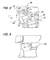
- FIG. 2 is a partial isometric view of the revolver of FIG. 1 in an open configuration
- FIG. 3 is an isometric view of a component of the revolver shown in FIG. 1 as seen from the right side;
- FIG. 4 is sectional views taken at line 4 - 4 in FIG. 2 ;
- FIGS. 5 and 6 are sectional views illustrating operation of an example detent according to the invention.
- FIG. 1 shows an example revolver 10 comprising a frame 12 including a grip 14 and a trigger guard 16 .
- a barrel 18 is attached to the frame.
- Revolver 10 is a “swing-out” type revolver and thus has a cylinder 20 mounted on a yoke 22 .
- Yoke 22 is mounted on frame 12 and is moveable about a pivot axis 24 between a closed position ( FIG. 1 ) and an open position ( FIG. 2 ).
- FIG. 3 shows a reverse view of yoke 22 , the yoke having a recess 26 , described in more detail below.
- FIGS. 2 and 4 show an example detent mechanism 28 .
- Detent mechanism 28 comprises a housing 30 mounted on frame 12 adjacent to yoke 22 .
- a pin bore 32 is positioned within the housing 30 .
- Pin bore 32 extends longitudinally along a pin bore axis 34 .
- the pin bore axis 34 is parallel to the pivot axis 24 of yoke 22 .
- a plunger cavity 36 is also positioned within housing 30 .
- Plunger cavity 36 intersects the pin bore 32 and extends along a plunger cavity axis 38 which is oriented transversely to the pin bore axis 34 .
- the plunger cavity axis 38 and the pin bore axis 32 are at right angles to one another.
- the plunger cavity 36 comprises an open end 40 , which terminates on a surface 42 of housing 30 , and a closed end 44 terminating within the housing.
- a pin 46 is positioned within the pin bore 32 .
- pin 46 has a round cross section and comprises a cylindrical body 48 having a tip 50 and an oppositely disposed end 52 .
- both tip 50 and opposite end 52 comprise respective conical surfaces 54 and 56 .
- Conical surfaces 54 and 56 have cone angles 58 from about 30° to about 60° as measured relatively to the pin bore axis 34 .
- a cone angle of about 45° is considered advantageous.
- Other shapes for tip 50 and opposite end 52 such as a hemispherical shape, are also feasible.
- pin 46 is movable along pin bore axis 34 between a first position ( FIGS. 2 and 5 ) wherein tip 50 projects from housing 30 , and a second position ( FIG. 6 ) wherein the tip 50 is within the housing 30 .
- first position FIGS. 2 and 5
- second position FIG. 6
- pin 46 is in the first position with tip 50 projecting from housing 30 and engaging the recess 26 in the yoke 22 (see FIGS. 3 and 5 ).
- Pin 46 thus acts as a detent to retain the yoke 22 in the closed position.
- pin 46 is moved along pin bore axis 34 to the second position ( FIG.
- housing 30 is arranged so that the open end 40 of the plunger cavity 36 faces yoke 22 when the yoke is in the closed position, as may be inferred from FIGS. 1 and 2 .
- plunger 60 Motion of pin 46 between the first and second positions shown in FIGS. 5 and 6 is governed by its interaction with a plunger 60 .
- plunger 60 is positioned within the plunger cavity 36 and is movable along plunger cavity axis 38 .
- plunger 60 has a round cross section and comprises a cylindrical body 62 .
- Plunger 60 is biased toward the open end 40 of plunger cavity 36 by a spring 64 positioned between the plunger 60 and the closed end 44 of the plunger cavity 36 .
- Spring 64 in this example is a coil spring, but other types of springs are also feasible.
- Plunger 60 has an end 66 which is biased by spring 64 into engagement with an action surface 68 positioned on pin 46 .
- Action surface 68 is oriented transversely to the pin bore axis 34 and comprises a surface of a notch 70 formed in cylindrical body 48 .
- the notch 70 is a symmetrical “V”-shaped notch and may be considered to have two action surfaces 68 , but other notch shapes are feasible.
- One or both action surfaces 68 are angularly oriented with respect to the pine bore axis 34 and have an orientation angle 72 from about 30° to about 60°, with an orientation angle of about 45° being advantageous.
- end 66 of plunger 60 which engages action surfaces 68 comprises at least one end surface 74 angularly oriented with respect to the plunger cavity axis 38 .
- End surface 74 has an orientation angle 76 from about 30° to about 60°, with an orientation angle of about 45° being advantageous.
- end 66 of plunger 60 has two end surfaces 74 arranged symmetrically. It is further advantageous that there be a difference in the orientation angles 72 of the action surfaces 68 as compared with the orientation angles 76 of the end surfaces 74 as shown in FIG. 4 .
- Angular differences 78 from about 1° to about 3° are considered practical.
- Assembly of the detent mechanism 28 is simplified by the configuration of the pin bore 32 and plunger cavity 36 in housing 30 .
- Spring 64 is first inserted into the plunger cavity 36 through its open end 40 followed by the plunger 60 . Care is taken to align the plunger end surfaces 74 in facing relation with the pin bore axis 34 .
- the pin 46 is then inserted into the pin bore 32 (from either end if the pin bore is a through bore open at both ends). Engagement between either the conical surface 54 of tip 50 of pin 46 or the conical surface 56 of the opposite end 52 of the pin 46 and one of the end surfaces 74 of plunger 60 will force the plunger toward the closed end 44 of the plunger cavity 36 , compressing spring 64 .
- the angular orientation of the engaging surfaces facilitates motion of the plunger 60 along the plunger cavity axis 38 as the pin 46 is moved along the pin bore axis 34 .
- spring 64 biases the plunger end surfaces 74 into engagement with the action surfaces 68 of pin 46 as shown in FIG. 4 .
- the pin 46 is thus captured within the pin bore 32 by mechanical engagement with the plunger 60 , biased into the notch 70 by spring 64 . If the pin bore 32 is a through bore as shown in the example embodiment herein, then disassembly is possible using a punch, applied at one end of the pin bore, to force the pin 46 out of the opposite end of the pin bore.
- FIGS. 5 and 6 Operation of the detent mechanism 28 when used on revolver 10 is illustrated in FIGS. 5 and 6 .
- the yoke 22 is in the closed position (see also FIG. 1 ) wherein the tip 50 of pin 46 projects outwardly from housing 30 and engages the recess 26 in the yoke 22 .
- Mechanical engagement between the pin 46 and recess 26 maintains the yoke 22 in the closed position so that the chambers 80 (see FIG. 2 ) of the cylinder 20 align with barrel 18 (see FIG. 1 ) during firing of the revolver.
- the geometry and tolerances of the recess 26 , pin 46 and plunger 60 are such that spring 64 biases plunger end surface 74 into engagement with pin action surface 68 so as to force conical surface 54 of tip 50 of pin 46 into engagement with a surface 82 of recess 26 .
- Surface 82 is advantageously angularly oriented with respect to pin bore axis 34 at an orientation angle 84 that matches the cone angle 58 of tip 50 .
- Revolvers having a detent mechanism according to the invention are expected to provide reliable operation with a simplified mechanism for maintaining the revolver closed with precise alignment between chamber and barrel.
Landscapes
- Engineering & Computer Science (AREA)
- General Engineering & Computer Science (AREA)
- Measuring Leads Or Probes (AREA)
- Snaps, Bayonet Connections, Set Pins, And Snap Rings (AREA)
- Mechanical Control Devices (AREA)
- Braking Systems And Boosters (AREA)
- Fluid-Damping Devices (AREA)
- Mechanical Pencils And Projecting And Retracting Systems Therefor, And Multi-System Writing Instruments (AREA)
- Pivots And Pivotal Connections (AREA)
- Food-Manufacturing Devices (AREA)
Abstract
Description
Claims (18)
Priority Applications (10)
| Application Number | Priority Date | Filing Date | Title |
|---|---|---|---|
| US14/994,773 US9810506B2 (en) | 2016-01-13 | 2016-01-13 | Self-captured detent mechinism |
| JP2018532385A JP6570157B2 (en) | 2016-01-13 | 2017-01-13 | Self-trapping detent mechanism |
| AU2017206821A AU2017206821B2 (en) | 2016-01-13 | 2017-01-13 | Self-captured detent mechanism |
| MX2018008618A MX2018008618A (en) | 2016-01-13 | 2017-01-13 | Self-captured detent mechanism. |
| CA3010516A CA3010516C (en) | 2016-01-13 | 2017-01-13 | Self-captured detent mechanism |
| PCT/US2017/013325 WO2017123861A1 (en) | 2016-01-13 | 2017-01-13 | Self-captured detent mechanism |
| KR1020187022670A KR102096882B1 (en) | 2016-01-13 | 2017-01-13 | Self-detained detent mechanism |
| EP17738997.0A EP3403043B1 (en) | 2016-01-13 | 2017-01-13 | Self-captured detent mechanism |
| US15/719,716 US20180023917A1 (en) | 2016-01-13 | 2017-09-29 | Self-Captured Detent Mechanism |
| AU2018271362A AU2018271362A1 (en) | 2016-01-13 | 2018-11-30 | Self-captured detent mechanism |
Applications Claiming Priority (1)
| Application Number | Priority Date | Filing Date | Title |
|---|---|---|---|
| US14/994,773 US9810506B2 (en) | 2016-01-13 | 2016-01-13 | Self-captured detent mechinism |
Related Child Applications (1)
| Application Number | Title | Priority Date | Filing Date |
|---|---|---|---|
| US15/719,716 Continuation US20180023917A1 (en) | 2016-01-13 | 2017-09-29 | Self-Captured Detent Mechanism |
Publications (2)
| Publication Number | Publication Date |
|---|---|
| US20170199005A1 US20170199005A1 (en) | 2017-07-13 |
| US9810506B2 true US9810506B2 (en) | 2017-11-07 |
Family
ID=59274902
Family Applications (2)
| Application Number | Title | Priority Date | Filing Date |
|---|---|---|---|
| US14/994,773 Active 2036-06-29 US9810506B2 (en) | 2016-01-13 | 2016-01-13 | Self-captured detent mechinism |
| US15/719,716 Abandoned US20180023917A1 (en) | 2016-01-13 | 2017-09-29 | Self-Captured Detent Mechanism |
Family Applications After (1)
| Application Number | Title | Priority Date | Filing Date |
|---|---|---|---|
| US15/719,716 Abandoned US20180023917A1 (en) | 2016-01-13 | 2017-09-29 | Self-Captured Detent Mechanism |
Country Status (8)
| Country | Link |
|---|---|
| US (2) | US9810506B2 (en) |
| EP (1) | EP3403043B1 (en) |
| JP (1) | JP6570157B2 (en) |
| KR (1) | KR102096882B1 (en) |
| AU (2) | AU2017206821B2 (en) |
| CA (1) | CA3010516C (en) |
| MX (1) | MX2018008618A (en) |
| WO (1) | WO2017123861A1 (en) |
Cited By (4)
| Publication number | Priority date | Publication date | Assignee | Title |
|---|---|---|---|---|
| US11215417B2 (en) | 2019-07-29 | 2022-01-04 | Sturm, Ruger & Company, Inc. | Safety mechanism for hammer-operated firearms |
| US20230228515A1 (en) * | 2022-01-16 | 2023-07-20 | Shadow Systems LLC | Firearm muzzle accessory |
| US12104870B2 (en) | 2023-01-11 | 2024-10-01 | Shadow Systems LLC | Quick-connect muzzle accessory |
| US12379179B2 (en) | 2022-01-16 | 2025-08-05 | Shadow Systems LLC | Firearm muzzle accessory |
Citations (78)
| Publication number | Priority date | Publication date | Assignee | Title |
|---|---|---|---|---|
| US702607A (en) * | 1902-01-02 | 1902-06-17 | Joseph H Wesson | Revolving firearm. |
| US1049105A (en) * | 1911-05-05 | 1912-12-31 | William Warren Key | Revolver. |
| US1141256A (en) * | 1912-12-18 | 1915-06-01 | Savage Arms Company | Tubular-magazine rifle. |
| US1334154A (en) * | 1920-03-16 | Socket-wrench | ||
| US1362478A (en) * | 1918-05-16 | 1920-12-14 | Homer H Deitrich | Shotgun |
| US1411800A (en) * | 1921-05-23 | 1922-04-04 | William J Molloy | Convertible revolver pistol |
| US1583617A (en) * | 1925-08-27 | 1926-05-04 | Louis P Smith | Safety mechanism for firearms |
| US1624876A (en) * | 1925-08-27 | 1927-04-12 | Ithaca Gun Co | Danger signal for firearms |
| US1925174A (en) * | 1931-08-03 | 1933-09-05 | William F Cremean | Key bolt or self-locking pin |
| US1930864A (en) * | 1931-03-09 | 1933-10-17 | Schmeisser Hugo | Automatic firearm |
| US2122415A (en) * | 1936-05-26 | 1938-07-05 | Le Roy B Fraser | Gun |
| US2125933A (en) * | 1936-05-14 | 1938-08-09 | Winchester Repeating Arms Co | Safety device for firearms |
| US2382676A (en) * | 1943-04-28 | 1945-08-14 | Colt S Mfg Co | Revolver crane lock |
| US2399904A (en) * | 1943-03-25 | 1946-05-07 | Sidney S Anderson | Device for loading revolver chambers simultaneously |
| US2407696A (en) * | 1945-06-07 | 1946-09-17 | George C Webster | Detent mechanism |
| US2455990A (en) * | 1947-01-07 | 1948-12-14 | Lloyd P Gaugler | Safety device for firearms |
| US2465699A (en) * | 1946-12-12 | 1949-03-29 | Savage Arms Corp | Top safety device for rifles |
| US2478892A (en) * | 1946-04-24 | 1949-08-16 | Frederick L Bistoff | Safety for firearms |
| US2809565A (en) * | 1954-01-08 | 1957-10-15 | John F O'brien | Firing mechanism for a revolver-type gun |
| US2821040A (en) * | 1955-12-29 | 1958-01-28 | James L Tatman | Safety for firearms |
| US2867930A (en) * | 1956-01-23 | 1959-01-13 | Casimer M Niesp | Thumb-operated trigger safety |
| US2875545A (en) * | 1956-08-13 | 1959-03-03 | Edward I Westmoreland | Revolver cocking mechanism actuated by side lever |
| US2909940A (en) * | 1956-03-22 | 1959-10-27 | Collins Radio Co | Detent mechanism |
| US2914877A (en) * | 1958-04-07 | 1959-12-01 | Thomas H Willenbacher | Trigger safety device for firearms |
| US2926445A (en) * | 1957-06-28 | 1960-03-01 | Noble Mfg Co Inc | Magazine gun with manual reloading mechanism |
| US3006096A (en) * | 1959-06-26 | 1961-10-31 | Noble Mfg Co Inc | Safety mechanism for slide action repeating firearm |
| US3212489A (en) * | 1963-04-05 | 1965-10-19 | Crosman Arms Company Inc | Gas-powered revolver |
| US3234679A (en) * | 1964-12-17 | 1966-02-15 | Mossberg & Sons O F | Thumb-operated safety for boltaction firearms |
| US3251153A (en) * | 1965-05-14 | 1966-05-17 | Herter Inc S | Revolver with spring-biased thrust arm |
| US3257749A (en) * | 1964-11-23 | 1966-06-28 | Browning Ind Inc | Straight pull bolt action rifle |
| US3270456A (en) * | 1964-12-17 | 1966-09-06 | Mossberg & Sons O F | Breech-bolt mechanism for bolt-action firearms |
| US3397640A (en) * | 1966-10-28 | 1968-08-20 | Gen Electric | Fuze with improved time delay and self-destruct mechanism |
| US3685193A (en) * | 1970-06-12 | 1972-08-22 | Ruger Sturm & Co Inc | Revolver cylinder retaining means |
| US3783545A (en) * | 1972-05-10 | 1974-01-08 | Sturm Ruger & Co | Loading lever arrangement for muzzle loading revolver |
| US3813804A (en) * | 1973-03-27 | 1974-06-04 | Sturm Ruger & Co | Revolver crane latch |
| US3830001A (en) * | 1972-05-10 | 1974-08-20 | Sturm Ruger & Co | Revolver cylinder pin and retaining means therefor |
| US4042305A (en) * | 1975-08-28 | 1977-08-16 | Vincent George E | Quick change snap lock connector |
| US4091557A (en) * | 1976-10-19 | 1978-05-30 | Frank Murabito | Safety for a revolver |
| US4422433A (en) * | 1982-05-24 | 1983-12-27 | The Coleman Company, Inc. | Projectile loader and detent assembly for guns |
| US4449312A (en) * | 1981-10-20 | 1984-05-22 | Sturm, Ruger & Company, Inc. | Mechanism adaptable for single action revolvers |
| US4614457A (en) * | 1985-07-15 | 1986-09-30 | Sammon James P | Coupling mechanism |
| US4651456A (en) * | 1983-10-21 | 1987-03-24 | Emilio Ghisoni | Revolver with reduced backlash moment |
| US4669324A (en) * | 1986-04-17 | 1987-06-02 | The Perkin-Elmer Corporation | Around-the-corner adjustment device |
| US4811511A (en) * | 1987-02-03 | 1989-03-14 | Fabbrica D'armi P. Beretta S.P.A. | Device for rapidly engaging and disengaging the trigger mechanism in the breech of a gun |
| US4845870A (en) * | 1987-09-03 | 1989-07-11 | Vernon Terry M | Firearm disabling apparatus |
| US4934081A (en) * | 1989-07-31 | 1990-06-19 | Smith & Wesson Corp. | Retainer for revolver yoke stud |
| US4964232A (en) * | 1989-08-30 | 1990-10-23 | U. S. Competition Arms, Inc. | Single barrel break-action trap shotgun |
| US5160795A (en) * | 1991-07-29 | 1992-11-03 | Crosman Corporation | Gun with pivoting barrel, rotary ammunition cylinder, and double action firing mechanism |
| US5463829A (en) * | 1992-08-11 | 1995-11-07 | U.S. Competition Arms Inc. | Method of removing a hammer from a shotgun |
| US5615507A (en) * | 1995-06-07 | 1997-04-01 | Thompson Intellectual Properties, Ltd. | Fire control mechanism for a firearm |
| US5787629A (en) * | 1995-09-28 | 1998-08-04 | Thompson & Campbell Limited | Firearms |
| US6006632A (en) * | 1998-06-25 | 1999-12-28 | Hsieh; Chih-Ching | Quick-release socket adapter for a ratchet socket wrench |
| US6062112A (en) * | 1995-11-14 | 2000-05-16 | Facom | Coupling device and rotary drive tool therefor |
| US6266908B1 (en) * | 1998-10-16 | 2001-07-31 | Smith & Wesson Corp. | Firearm frame and barrel assembly, method of assembling and assembly tool |
| US6360469B1 (en) * | 2000-07-14 | 2002-03-26 | Smith & Wesson Corp. | Electronically fired revolver utilizing percussively actuated cartridges |
| US20020148152A1 (en) * | 2001-04-12 | 2002-10-17 | Brett Curry | Revolver-safety lock mechanism |
| US6823762B2 (en) * | 2001-12-14 | 2004-11-30 | Bobby Hu | Wrench extension with a socket-coupling system |
| US6907687B2 (en) * | 2002-12-02 | 2005-06-21 | Browning Arms Company | Over-and-under shotgun apparatus and method |
| US7059075B1 (en) * | 2003-02-12 | 2006-06-13 | Smith & Wesson Corp. | Cylinder retaining mechanism |
| US20060191182A1 (en) * | 2004-12-22 | 2006-08-31 | Smith & Wesson Corp. | Locking apparatus for a firearm |
| US20060207147A1 (en) * | 2005-03-19 | 2006-09-21 | Lazor Ernest R | Self-contained triggerplate action for low profile firearms |
| US20060242878A1 (en) * | 2004-11-12 | 2006-11-02 | Smith & Wesson Corp. | Revolver for firing high velocity ammunition |
| US7156084B1 (en) * | 2003-06-30 | 2007-01-02 | Jdl Engineering, Llc | Paint-ball sport gun with adjustable detent assembly |
| US7263795B1 (en) * | 2003-02-11 | 2007-09-04 | Smith & Wesson Corp. | Extractor for a revolver |
| US7328645B1 (en) * | 2003-02-10 | 2008-02-12 | Smith & Wesson Corp. | Compensation system for a firearm |
| US7448823B2 (en) * | 2004-06-09 | 2008-11-11 | Fred Silva | Quick release shackle pin system |
| US7743543B2 (en) * | 2005-10-06 | 2010-06-29 | Theodore Karagias | Trigger mechanism and a firearm containing the same |
| US20100170129A1 (en) * | 2008-12-31 | 2010-07-08 | Smith & Wesson Corp. | Firearm having nonmetallic components |
| US7861449B1 (en) * | 2007-08-14 | 2011-01-04 | Sturm, Ruger & Company, Inc. | Cylinder latching mechanism for revolver |
| US7895924B2 (en) * | 2009-01-19 | 2011-03-01 | Chih-Ching Hsieh | Socket connection device |
| US8327568B1 (en) * | 2010-04-21 | 2012-12-11 | Lavergne Michael D | Gunstock system having an internal magazine |
| US8353124B1 (en) * | 2012-03-27 | 2013-01-15 | Smith & Wesson Corp. | Thixotropic molded barrel for firearm |
| US20130074391A1 (en) * | 2011-09-23 | 2013-03-28 | Smith & Wesson Corp. | Drop safety for a firing pin of a firearm |
| US8434255B2 (en) * | 2007-01-18 | 2013-05-07 | Steyr Mannlicher Holding Gmbh | Breech block for a drop-down barrel weapon |
| US20130111796A1 (en) * | 2011-11-07 | 2013-05-09 | Megamet Solid Metals, Inc | Firearm selector switch locking apparatus |
| US20130174459A1 (en) * | 2011-06-29 | 2013-07-11 | Benelli Armi S.P.A. | Interchangeable Trigger Assembly for Firearms |
| US20150096212A1 (en) * | 2013-10-09 | 2015-04-09 | Smith & Wesson Corp. | Slide Stop Retention Mechanism |
| WO2015200588A1 (en) | 2014-06-26 | 2015-12-30 | Sturm, Ruger & Company, Inc. | Firearm safety mechanism |
Family Cites Families (1)
| Publication number | Priority date | Publication date | Assignee | Title |
|---|---|---|---|---|
| US4835892A (en) * | 1984-06-25 | 1989-06-06 | Sturm, Ruger & Company, Inc. | Magazine latch for pistol |
-
2016
- 2016-01-13 US US14/994,773 patent/US9810506B2/en active Active
-
2017
- 2017-01-13 EP EP17738997.0A patent/EP3403043B1/en active Active
- 2017-01-13 AU AU2017206821A patent/AU2017206821B2/en active Active
- 2017-01-13 MX MX2018008618A patent/MX2018008618A/en unknown
- 2017-01-13 CA CA3010516A patent/CA3010516C/en active Active
- 2017-01-13 JP JP2018532385A patent/JP6570157B2/en active Active
- 2017-01-13 KR KR1020187022670A patent/KR102096882B1/en active Active
- 2017-01-13 WO PCT/US2017/013325 patent/WO2017123861A1/en not_active Ceased
- 2017-09-29 US US15/719,716 patent/US20180023917A1/en not_active Abandoned
-
2018
- 2018-11-30 AU AU2018271362A patent/AU2018271362A1/en not_active Abandoned
Patent Citations (82)
| Publication number | Priority date | Publication date | Assignee | Title |
|---|---|---|---|---|
| US1334154A (en) * | 1920-03-16 | Socket-wrench | ||
| US702607A (en) * | 1902-01-02 | 1902-06-17 | Joseph H Wesson | Revolving firearm. |
| US1049105A (en) * | 1911-05-05 | 1912-12-31 | William Warren Key | Revolver. |
| US1141256A (en) * | 1912-12-18 | 1915-06-01 | Savage Arms Company | Tubular-magazine rifle. |
| US1362478A (en) * | 1918-05-16 | 1920-12-14 | Homer H Deitrich | Shotgun |
| US1411800A (en) * | 1921-05-23 | 1922-04-04 | William J Molloy | Convertible revolver pistol |
| US1583617A (en) * | 1925-08-27 | 1926-05-04 | Louis P Smith | Safety mechanism for firearms |
| US1624876A (en) * | 1925-08-27 | 1927-04-12 | Ithaca Gun Co | Danger signal for firearms |
| US1930864A (en) * | 1931-03-09 | 1933-10-17 | Schmeisser Hugo | Automatic firearm |
| US1925174A (en) * | 1931-08-03 | 1933-09-05 | William F Cremean | Key bolt or self-locking pin |
| US2125933A (en) * | 1936-05-14 | 1938-08-09 | Winchester Repeating Arms Co | Safety device for firearms |
| US2122415A (en) * | 1936-05-26 | 1938-07-05 | Le Roy B Fraser | Gun |
| US2399904A (en) * | 1943-03-25 | 1946-05-07 | Sidney S Anderson | Device for loading revolver chambers simultaneously |
| US2382676A (en) * | 1943-04-28 | 1945-08-14 | Colt S Mfg Co | Revolver crane lock |
| US2407696A (en) * | 1945-06-07 | 1946-09-17 | George C Webster | Detent mechanism |
| US2478892A (en) * | 1946-04-24 | 1949-08-16 | Frederick L Bistoff | Safety for firearms |
| US2465699A (en) * | 1946-12-12 | 1949-03-29 | Savage Arms Corp | Top safety device for rifles |
| US2455990A (en) * | 1947-01-07 | 1948-12-14 | Lloyd P Gaugler | Safety device for firearms |
| US2809565A (en) * | 1954-01-08 | 1957-10-15 | John F O'brien | Firing mechanism for a revolver-type gun |
| US2821040A (en) * | 1955-12-29 | 1958-01-28 | James L Tatman | Safety for firearms |
| US2867930A (en) * | 1956-01-23 | 1959-01-13 | Casimer M Niesp | Thumb-operated trigger safety |
| US2909940A (en) * | 1956-03-22 | 1959-10-27 | Collins Radio Co | Detent mechanism |
| US2875545A (en) * | 1956-08-13 | 1959-03-03 | Edward I Westmoreland | Revolver cocking mechanism actuated by side lever |
| US2926445A (en) * | 1957-06-28 | 1960-03-01 | Noble Mfg Co Inc | Magazine gun with manual reloading mechanism |
| US2914877A (en) * | 1958-04-07 | 1959-12-01 | Thomas H Willenbacher | Trigger safety device for firearms |
| US3006096A (en) * | 1959-06-26 | 1961-10-31 | Noble Mfg Co Inc | Safety mechanism for slide action repeating firearm |
| US3212489A (en) * | 1963-04-05 | 1965-10-19 | Crosman Arms Company Inc | Gas-powered revolver |
| US3257749A (en) * | 1964-11-23 | 1966-06-28 | Browning Ind Inc | Straight pull bolt action rifle |
| US3234679A (en) * | 1964-12-17 | 1966-02-15 | Mossberg & Sons O F | Thumb-operated safety for boltaction firearms |
| US3270456A (en) * | 1964-12-17 | 1966-09-06 | Mossberg & Sons O F | Breech-bolt mechanism for bolt-action firearms |
| US3251153A (en) * | 1965-05-14 | 1966-05-17 | Herter Inc S | Revolver with spring-biased thrust arm |
| US3397640A (en) * | 1966-10-28 | 1968-08-20 | Gen Electric | Fuze with improved time delay and self-destruct mechanism |
| US3685193A (en) * | 1970-06-12 | 1972-08-22 | Ruger Sturm & Co Inc | Revolver cylinder retaining means |
| US3783545A (en) * | 1972-05-10 | 1974-01-08 | Sturm Ruger & Co | Loading lever arrangement for muzzle loading revolver |
| US3830001A (en) * | 1972-05-10 | 1974-08-20 | Sturm Ruger & Co | Revolver cylinder pin and retaining means therefor |
| US3813804A (en) * | 1973-03-27 | 1974-06-04 | Sturm Ruger & Co | Revolver crane latch |
| US4042305A (en) * | 1975-08-28 | 1977-08-16 | Vincent George E | Quick change snap lock connector |
| US4091557A (en) * | 1976-10-19 | 1978-05-30 | Frank Murabito | Safety for a revolver |
| US4449312A (en) * | 1981-10-20 | 1984-05-22 | Sturm, Ruger & Company, Inc. | Mechanism adaptable for single action revolvers |
| US4422433A (en) * | 1982-05-24 | 1983-12-27 | The Coleman Company, Inc. | Projectile loader and detent assembly for guns |
| US4651456A (en) * | 1983-10-21 | 1987-03-24 | Emilio Ghisoni | Revolver with reduced backlash moment |
| US4614457A (en) * | 1985-07-15 | 1986-09-30 | Sammon James P | Coupling mechanism |
| US4669324A (en) * | 1986-04-17 | 1987-06-02 | The Perkin-Elmer Corporation | Around-the-corner adjustment device |
| US4811511A (en) * | 1987-02-03 | 1989-03-14 | Fabbrica D'armi P. Beretta S.P.A. | Device for rapidly engaging and disengaging the trigger mechanism in the breech of a gun |
| US4845870A (en) * | 1987-09-03 | 1989-07-11 | Vernon Terry M | Firearm disabling apparatus |
| US4934081A (en) * | 1989-07-31 | 1990-06-19 | Smith & Wesson Corp. | Retainer for revolver yoke stud |
| US4964232A (en) * | 1989-08-30 | 1990-10-23 | U. S. Competition Arms, Inc. | Single barrel break-action trap shotgun |
| US5160795A (en) * | 1991-07-29 | 1992-11-03 | Crosman Corporation | Gun with pivoting barrel, rotary ammunition cylinder, and double action firing mechanism |
| US5463829A (en) * | 1992-08-11 | 1995-11-07 | U.S. Competition Arms Inc. | Method of removing a hammer from a shotgun |
| US5615507A (en) * | 1995-06-07 | 1997-04-01 | Thompson Intellectual Properties, Ltd. | Fire control mechanism for a firearm |
| US5787629A (en) * | 1995-09-28 | 1998-08-04 | Thompson & Campbell Limited | Firearms |
| US6062112A (en) * | 1995-11-14 | 2000-05-16 | Facom | Coupling device and rotary drive tool therefor |
| US6006632A (en) * | 1998-06-25 | 1999-12-28 | Hsieh; Chih-Ching | Quick-release socket adapter for a ratchet socket wrench |
| US6266908B1 (en) * | 1998-10-16 | 2001-07-31 | Smith & Wesson Corp. | Firearm frame and barrel assembly, method of assembling and assembly tool |
| US6360469B1 (en) * | 2000-07-14 | 2002-03-26 | Smith & Wesson Corp. | Electronically fired revolver utilizing percussively actuated cartridges |
| US20020148152A1 (en) * | 2001-04-12 | 2002-10-17 | Brett Curry | Revolver-safety lock mechanism |
| US6823762B2 (en) * | 2001-12-14 | 2004-11-30 | Bobby Hu | Wrench extension with a socket-coupling system |
| US6907687B2 (en) * | 2002-12-02 | 2005-06-21 | Browning Arms Company | Over-and-under shotgun apparatus and method |
| US7328645B1 (en) * | 2003-02-10 | 2008-02-12 | Smith & Wesson Corp. | Compensation system for a firearm |
| US7263795B1 (en) * | 2003-02-11 | 2007-09-04 | Smith & Wesson Corp. | Extractor for a revolver |
| US7059075B1 (en) * | 2003-02-12 | 2006-06-13 | Smith & Wesson Corp. | Cylinder retaining mechanism |
| US7156084B1 (en) * | 2003-06-30 | 2007-01-02 | Jdl Engineering, Llc | Paint-ball sport gun with adjustable detent assembly |
| US7448823B2 (en) * | 2004-06-09 | 2008-11-11 | Fred Silva | Quick release shackle pin system |
| US20060242878A1 (en) * | 2004-11-12 | 2006-11-02 | Smith & Wesson Corp. | Revolver for firing high velocity ammunition |
| US20060191182A1 (en) * | 2004-12-22 | 2006-08-31 | Smith & Wesson Corp. | Locking apparatus for a firearm |
| US20060207147A1 (en) * | 2005-03-19 | 2006-09-21 | Lazor Ernest R | Self-contained triggerplate action for low profile firearms |
| US7743543B2 (en) * | 2005-10-06 | 2010-06-29 | Theodore Karagias | Trigger mechanism and a firearm containing the same |
| US8434255B2 (en) * | 2007-01-18 | 2013-05-07 | Steyr Mannlicher Holding Gmbh | Breech block for a drop-down barrel weapon |
| US7861449B1 (en) * | 2007-08-14 | 2011-01-04 | Sturm, Ruger & Company, Inc. | Cylinder latching mechanism for revolver |
| US8549782B2 (en) | 2008-12-31 | 2013-10-08 | Smith & Wesson Corp. | Firearm having an indexing mechanism |
| US20100170129A1 (en) * | 2008-12-31 | 2010-07-08 | Smith & Wesson Corp. | Firearm having nonmetallic components |
| US8789303B2 (en) | 2008-12-31 | 2014-07-29 | Smith & Wesson Corp. | Firing pin blocking safety |
| US20140331536A1 (en) | 2008-12-31 | 2014-11-13 | Smith & Wesson Corp. | Yoke And Cylinder Retaining Mechanism |
| US7895924B2 (en) * | 2009-01-19 | 2011-03-01 | Chih-Ching Hsieh | Socket connection device |
| US8327568B1 (en) * | 2010-04-21 | 2012-12-11 | Lavergne Michael D | Gunstock system having an internal magazine |
| US20130174459A1 (en) * | 2011-06-29 | 2013-07-11 | Benelli Armi S.P.A. | Interchangeable Trigger Assembly for Firearms |
| US20130074391A1 (en) * | 2011-09-23 | 2013-03-28 | Smith & Wesson Corp. | Drop safety for a firing pin of a firearm |
| US20130111796A1 (en) * | 2011-11-07 | 2013-05-09 | Megamet Solid Metals, Inc | Firearm selector switch locking apparatus |
| US8353124B1 (en) * | 2012-03-27 | 2013-01-15 | Smith & Wesson Corp. | Thixotropic molded barrel for firearm |
| US20150096212A1 (en) * | 2013-10-09 | 2015-04-09 | Smith & Wesson Corp. | Slide Stop Retention Mechanism |
| WO2015200588A1 (en) | 2014-06-26 | 2015-12-30 | Sturm, Ruger & Company, Inc. | Firearm safety mechanism |
| US9476660B2 (en) * | 2014-06-26 | 2016-10-25 | Sturm, Ruger & Company, Inc. | Firearm safety mechanism |
Non-Patent Citations (1)
| Title |
|---|
| Young, Lee W.; PCT International Search Report and Written Opinion regarding International Application No. PCT/US17/13325, May 5, 2017. |
Cited By (6)
| Publication number | Priority date | Publication date | Assignee | Title |
|---|---|---|---|---|
| US11215417B2 (en) | 2019-07-29 | 2022-01-04 | Sturm, Ruger & Company, Inc. | Safety mechanism for hammer-operated firearms |
| US20230228515A1 (en) * | 2022-01-16 | 2023-07-20 | Shadow Systems LLC | Firearm muzzle accessory |
| US11874078B2 (en) * | 2022-01-16 | 2024-01-16 | Shadow Systems LLC | Firearm muzzle accessory |
| US12379179B2 (en) | 2022-01-16 | 2025-08-05 | Shadow Systems LLC | Firearm muzzle accessory |
| US12104870B2 (en) | 2023-01-11 | 2024-10-01 | Shadow Systems LLC | Quick-connect muzzle accessory |
| US12546552B2 (en) | 2023-01-11 | 2026-02-10 | Shadow Systems LLC | Quick-connect muzzle accessory |
Also Published As
| Publication number | Publication date |
|---|---|
| JP2019501349A (en) | 2019-01-17 |
| AU2017206821B2 (en) | 2019-03-28 |
| US20180023917A1 (en) | 2018-01-25 |
| EP3403043B1 (en) | 2020-06-10 |
| US20170199005A1 (en) | 2017-07-13 |
| AU2018271362A1 (en) | 2019-01-03 |
| KR102096882B1 (en) | 2020-04-06 |
| CA3010516A1 (en) | 2017-07-20 |
| AU2017206821A1 (en) | 2018-06-07 |
| EP3403043A1 (en) | 2018-11-21 |
| CA3010516C (en) | 2020-04-21 |
| EP3403043A4 (en) | 2020-02-19 |
| KR20180109065A (en) | 2018-10-05 |
| MX2018008618A (en) | 2018-11-19 |
| JP6570157B2 (en) | 2019-09-04 |
| WO2017123861A1 (en) | 2017-07-20 |
Similar Documents
| Publication | Publication Date | Title |
|---|---|---|
| US20180023917A1 (en) | Self-Captured Detent Mechanism | |
| US7908781B2 (en) | Muzzle loading firearm with break-open action | |
| EP3011253B1 (en) | Conversion set for a firearm and method for converting a firearm | |
| US10036600B2 (en) | Bolt for firearms and cam pin therefor | |
| US9016187B2 (en) | Pump action rifle and action lock mechanism | |
| US10041751B2 (en) | Rotary lockup action | |
| US5046275A (en) | Conversion kit for semiautomatic weapons | |
| US10247500B2 (en) | Modular bolt assembly with floating fire pin | |
| US10323892B2 (en) | Pellet loading system | |
| US10605554B2 (en) | Laterally pivoting trigger lever | |
| US20200300567A1 (en) | Cartridge Extractor | |
| WO2021091500A1 (en) | Double-sided magazine change mechanism | |
| WO2018013650A1 (en) | Firearm bolt configured to prevent the firing of a conventional cartridge | |
| US806007A (en) | Firearm. | |
| DE229520C (en) | ||
| US779093A (en) | Toy cannon. | |
| US505568A (en) | Breech-block | |
| USRE237E (en) | Improved cannon-lock | |
| US523289A (en) | luscomb | |
| US523979A (en) | Stop for rimless cartridges | |
| DE1217244B (en) | Multiple loading device for gas guns | |
| HK40000683B (en) | Break barrel rifle with pellet loading system | |
| HK40000683A (en) | Break barrel rifle with pellet loading system | |
| WO2013098753A2 (en) | Automatic case-extraction and -expulsion system using a ratchet, for a 12-, 16- and 20-caliber single-shot long gun |
Legal Events
| Date | Code | Title | Description |
|---|---|---|---|
| AS | Assignment |
Owner name: SMITH & WESSON CORP., MASSACHUSETTS Free format text: ASSIGNMENT OF ASSIGNORS INTEREST;ASSIGNOR:CURRY, BRETT;REEL/FRAME:037489/0133 Effective date: 20160111 |
|
| STCF | Information on status: patent grant |
Free format text: PATENTED CASE |
|
| AS | Assignment |
Owner name: AMERICAN OUTDOOR BRANDS SALES COMPANY, MASSACHUSET Free format text: CHANGE OF NAME;ASSIGNOR:SMITH & WESSON CORP.;REEL/FRAME:049507/0562 Effective date: 20190617 Owner name: AMERICAN OUTDOOR BRANDS SALES COMPANY, MASSACHUSETTS Free format text: CHANGE OF NAME;ASSIGNOR:SMITH & WESSON CORP.;REEL/FRAME:049507/0562 Effective date: 20190617 |
|
| AS | Assignment |
Owner name: SMITH & WESSON INC., MASSACHUSETTS Free format text: ASSIGNMENT OF ASSIGNORS INTEREST;ASSIGNOR:AMERICAN OUTDOOR BRANDS SALES COMPANY;REEL/FRAME:049572/0919 Effective date: 20190619 |
|
| MAFP | Maintenance fee payment |
Free format text: PAYMENT OF MAINTENANCE FEE, 4TH YEAR, LARGE ENTITY (ORIGINAL EVENT CODE: M1551); ENTITY STATUS OF PATENT OWNER: LARGE ENTITY Year of fee payment: 4 |
|
| MAFP | Maintenance fee payment |
Free format text: PAYMENT OF MAINTENANCE FEE, 8TH YEAR, LARGE ENTITY (ORIGINAL EVENT CODE: M1552); ENTITY STATUS OF PATENT OWNER: LARGE ENTITY Year of fee payment: 8 |