US9809464B2 - Apparatus for harvesting algae from open body of water - Google Patents
Apparatus for harvesting algae from open body of water Download PDFInfo
- Publication number
- US9809464B2 US9809464B2 US14/540,309 US201414540309A US9809464B2 US 9809464 B2 US9809464 B2 US 9809464B2 US 201414540309 A US201414540309 A US 201414540309A US 9809464 B2 US9809464 B2 US 9809464B2
- Authority
- US
- United States
- Prior art keywords
- algae
- process channel
- water
- open body
- members
- Prior art date
- Legal status (The legal status is an assumption and is not a legal conclusion. Google has not performed a legal analysis and makes no representation as to the accuracy of the status listed.)
- Active, expires
Links
Images


Classifications
-
- C—CHEMISTRY; METALLURGY
- C02—TREATMENT OF WATER, WASTE WATER, SEWAGE, OR SLUDGE
- C02F—TREATMENT OF WATER, WASTE WATER, SEWAGE, OR SLUDGE
- C02F1/00—Treatment of water, waste water, or sewage
- C02F1/24—Treatment of water, waste water, or sewage by flotation
-
- A—HUMAN NECESSITIES
- A01—AGRICULTURE; FORESTRY; ANIMAL HUSBANDRY; HUNTING; TRAPPING; FISHING
- A01D—HARVESTING; MOWING
- A01D44/00—Harvesting of underwater plants, e.g. harvesting of seaweed
-
- A—HUMAN NECESSITIES
- A01—AGRICULTURE; FORESTRY; ANIMAL HUSBANDRY; HUNTING; TRAPPING; FISHING
- A01G—HORTICULTURE; CULTIVATION OF VEGETABLES, FLOWERS, RICE, FRUIT, VINES, HOPS OR SEAWEED; FORESTRY; WATERING
- A01G33/00—Cultivation of seaweed or algae
-
- B—PERFORMING OPERATIONS; TRANSPORTING
- B03—SEPARATION OF SOLID MATERIALS USING LIQUIDS OR USING PNEUMATIC TABLES OR JIGS; MAGNETIC OR ELECTROSTATIC SEPARATION OF SOLID MATERIALS FROM SOLID MATERIALS OR FLUIDS; SEPARATION BY HIGH-VOLTAGE ELECTRIC FIELDS
- B03D—FLOTATION; DIFFERENTIAL SEDIMENTATION
- B03D1/00—Flotation
- B03D1/14—Flotation machines
- B03D1/1431—Dissolved air flotation machines
-
- B—PERFORMING OPERATIONS; TRANSPORTING
- B63—SHIPS OR OTHER WATERBORNE VESSELS; RELATED EQUIPMENT
- B63B—SHIPS OR OTHER WATERBORNE VESSELS; EQUIPMENT FOR SHIPPING
- B63B35/00—Vessels or similar floating structures specially adapted for specific purposes and not otherwise provided for
- B63B35/32—Vessels or similar floating structures specially adapted for specific purposes and not otherwise provided for for collecting pollution from open water
-
- C—CHEMISTRY; METALLURGY
- C10—PETROLEUM, GAS OR COKE INDUSTRIES; TECHNICAL GASES CONTAINING CARBON MONOXIDE; FUELS; LUBRICANTS; PEAT
- C10L—FUELS NOT OTHERWISE PROVIDED FOR; NATURAL GAS; SYNTHETIC NATURAL GAS OBTAINED BY PROCESSES NOT COVERED BY SUBCLASSES C10G OR C10K; LIQUIFIED PETROLEUM GAS; USE OF ADDITIVES TO FUELS OR FIRES; FIRE-LIGHTERS
- C10L5/00—Solid fuels
- C10L5/40—Solid fuels essentially based on materials of non-mineral origin
- C10L5/44—Solid fuels essentially based on materials of non-mineral origin on vegetable substances
- C10L5/445—Agricultural waste, e.g. corn crops, grass clippings, nut shells or oil pressing residues
-
- C—CHEMISTRY; METALLURGY
- C12—BIOCHEMISTRY; BEER; SPIRITS; WINE; VINEGAR; MICROBIOLOGY; ENZYMOLOGY; MUTATION OR GENETIC ENGINEERING
- C12M—APPARATUS FOR ENZYMOLOGY OR MICROBIOLOGY; APPARATUS FOR CULTURING MICROORGANISMS FOR PRODUCING BIOMASS, FOR GROWING CELLS OR FOR OBTAINING FERMENTATION OR METABOLIC PRODUCTS, i.e. BIOREACTORS OR FERMENTERS
- C12M21/00—Bioreactors or fermenters specially adapted for specific uses
- C12M21/02—Photobioreactors
-
- C—CHEMISTRY; METALLURGY
- C12—BIOCHEMISTRY; BEER; SPIRITS; WINE; VINEGAR; MICROBIOLOGY; ENZYMOLOGY; MUTATION OR GENETIC ENGINEERING
- C12M—APPARATUS FOR ENZYMOLOGY OR MICROBIOLOGY; APPARATUS FOR CULTURING MICROORGANISMS FOR PRODUCING BIOMASS, FOR GROWING CELLS OR FOR OBTAINING FERMENTATION OR METABOLIC PRODUCTS, i.e. BIOREACTORS OR FERMENTERS
- C12M23/00—Constructional details, e.g. recesses, hinges
- C12M23/02—Form or structure of the vessel
- C12M23/18—Open ponds; Greenhouse type or underground installations
-
- C—CHEMISTRY; METALLURGY
- C12—BIOCHEMISTRY; BEER; SPIRITS; WINE; VINEGAR; MICROBIOLOGY; ENZYMOLOGY; MUTATION OR GENETIC ENGINEERING
- C12M—APPARATUS FOR ENZYMOLOGY OR MICROBIOLOGY; APPARATUS FOR CULTURING MICROORGANISMS FOR PRODUCING BIOMASS, FOR GROWING CELLS OR FOR OBTAINING FERMENTATION OR METABOLIC PRODUCTS, i.e. BIOREACTORS OR FERMENTERS
- C12M23/00—Constructional details, e.g. recesses, hinges
- C12M23/56—Floating elements
-
- C—CHEMISTRY; METALLURGY
- C12—BIOCHEMISTRY; BEER; SPIRITS; WINE; VINEGAR; MICROBIOLOGY; ENZYMOLOGY; MUTATION OR GENETIC ENGINEERING
- C12M—APPARATUS FOR ENZYMOLOGY OR MICROBIOLOGY; APPARATUS FOR CULTURING MICROORGANISMS FOR PRODUCING BIOMASS, FOR GROWING CELLS OR FOR OBTAINING FERMENTATION OR METABOLIC PRODUCTS, i.e. BIOREACTORS OR FERMENTERS
- C12M33/00—Means for introduction, transport, positioning, extraction, harvesting, peeling or sampling of biological material in or from the apparatus
-
- C—CHEMISTRY; METALLURGY
- C12—BIOCHEMISTRY; BEER; SPIRITS; WINE; VINEGAR; MICROBIOLOGY; ENZYMOLOGY; MUTATION OR GENETIC ENGINEERING
- C12M—APPARATUS FOR ENZYMOLOGY OR MICROBIOLOGY; APPARATUS FOR CULTURING MICROORGANISMS FOR PRODUCING BIOMASS, FOR GROWING CELLS OR FOR OBTAINING FERMENTATION OR METABOLIC PRODUCTS, i.e. BIOREACTORS OR FERMENTERS
- C12M47/00—Means for after-treatment of the produced biomass or of the fermentation or metabolic products, e.g. storage of biomass
- C12M47/02—Separating microorganisms from the culture medium; Concentration of biomass
-
- E—FIXED CONSTRUCTIONS
- E02—HYDRAULIC ENGINEERING; FOUNDATIONS; SOIL SHIFTING
- E02B—HYDRAULIC ENGINEERING
- E02B15/00—Cleaning or keeping clear the surface of open water; Apparatus therefor
- E02B15/04—Devices for cleaning or keeping clear the surface of open water from oil or like floating materials by separating or removing these materials
-
- B—PERFORMING OPERATIONS; TRANSPORTING
- B03—SEPARATION OF SOLID MATERIALS USING LIQUIDS OR USING PNEUMATIC TABLES OR JIGS; MAGNETIC OR ELECTROSTATIC SEPARATION OF SOLID MATERIALS FROM SOLID MATERIALS OR FLUIDS; SEPARATION BY HIGH-VOLTAGE ELECTRIC FIELDS
- B03D—FLOTATION; DIFFERENTIAL SEDIMENTATION
- B03D2203/00—Specified materials treated by the flotation agents; Specified applications
- B03D2203/001—Agricultural products, food, biogas, algae
-
- B—PERFORMING OPERATIONS; TRANSPORTING
- B63—SHIPS OR OTHER WATERBORNE VESSELS; RELATED EQUIPMENT
- B63B—SHIPS OR OTHER WATERBORNE VESSELS; EQUIPMENT FOR SHIPPING
- B63B35/00—Vessels or similar floating structures specially adapted for specific purposes and not otherwise provided for
- B63B35/34—Pontoons
-
- C—CHEMISTRY; METALLURGY
- C02—TREATMENT OF WATER, WASTE WATER, SEWAGE, OR SLUDGE
- C02F—TREATMENT OF WATER, WASTE WATER, SEWAGE, OR SLUDGE
- C02F2103/00—Nature of the water, waste water, sewage or sludge to be treated
- C02F2103/007—Contaminated open waterways, rivers, lakes or ponds
-
- C—CHEMISTRY; METALLURGY
- C02—TREATMENT OF WATER, WASTE WATER, SEWAGE, OR SLUDGE
- C02F—TREATMENT OF WATER, WASTE WATER, SEWAGE, OR SLUDGE
- C02F2201/00—Apparatus for treatment of water, waste water or sewage
- C02F2201/008—Mobile apparatus and plants, e.g. mounted on a vehicle
-
- C—CHEMISTRY; METALLURGY
- C02—TREATMENT OF WATER, WASTE WATER, SEWAGE, OR SLUDGE
- C02F—TREATMENT OF WATER, WASTE WATER, SEWAGE, OR SLUDGE
- C02F2301/00—General aspects of water treatment
- C02F2301/06—Pressure conditions
- C02F2301/066—Overpressure, high pressure
-
- Y—GENERAL TAGGING OF NEW TECHNOLOGICAL DEVELOPMENTS; GENERAL TAGGING OF CROSS-SECTIONAL TECHNOLOGIES SPANNING OVER SEVERAL SECTIONS OF THE IPC; TECHNICAL SUBJECTS COVERED BY FORMER USPC CROSS-REFERENCE ART COLLECTIONS [XRACs] AND DIGESTS
- Y02—TECHNOLOGIES OR APPLICATIONS FOR MITIGATION OR ADAPTATION AGAINST CLIMATE CHANGE
- Y02A—TECHNOLOGIES FOR ADAPTATION TO CLIMATE CHANGE
- Y02A40/00—Adaptation technologies in agriculture, forestry, livestock or agroalimentary production
- Y02A40/80—Adaptation technologies in agriculture, forestry, livestock or agroalimentary production in fisheries management
-
- Y—GENERAL TAGGING OF NEW TECHNOLOGICAL DEVELOPMENTS; GENERAL TAGGING OF CROSS-SECTIONAL TECHNOLOGIES SPANNING OVER SEVERAL SECTIONS OF THE IPC; TECHNICAL SUBJECTS COVERED BY FORMER USPC CROSS-REFERENCE ART COLLECTIONS [XRACs] AND DIGESTS
- Y02—TECHNOLOGIES OR APPLICATIONS FOR MITIGATION OR ADAPTATION AGAINST CLIMATE CHANGE
- Y02E—REDUCTION OF GREENHOUSE GAS [GHG] EMISSIONS, RELATED TO ENERGY GENERATION, TRANSMISSION OR DISTRIBUTION
- Y02E50/00—Technologies for the production of fuel of non-fossil origin
- Y02E50/10—Biofuels, e.g. bio-diesel
-
- Y—GENERAL TAGGING OF NEW TECHNOLOGICAL DEVELOPMENTS; GENERAL TAGGING OF CROSS-SECTIONAL TECHNOLOGIES SPANNING OVER SEVERAL SECTIONS OF THE IPC; TECHNICAL SUBJECTS COVERED BY FORMER USPC CROSS-REFERENCE ART COLLECTIONS [XRACs] AND DIGESTS
- Y02—TECHNOLOGIES OR APPLICATIONS FOR MITIGATION OR ADAPTATION AGAINST CLIMATE CHANGE
- Y02E—REDUCTION OF GREENHOUSE GAS [GHG] EMISSIONS, RELATED TO ENERGY GENERATION, TRANSMISSION OR DISTRIBUTION
- Y02E50/00—Technologies for the production of fuel of non-fossil origin
- Y02E50/30—Fuel from waste, e.g. synthetic alcohol or diesel
Definitions
- This invention relates to water treatment by dissolved air floatation and, more particularly, harvesting algae from an open body of water utilizing dissolved air floatation technology.
- DAF Dissolved air flotation
- wastewaters or other waters
- the removal is achieved by dissolving air in the water or wastewater under pressure and then releasing the air at atmospheric pressure in a flotation tank or basin.
- the released air forms tiny bubbles which adhere to the suspended matter causing the suspended matter to float to the surface of the water where it may then be removed by a skimming device.
- Dissolved air flotation is very widely used in treating the industrial wastewater effluents from oil refineries, petrochemical and chemical plants, natural gas processing plants, paper mills, general water treatment and similar industrial facilities.
- a very similar process known as induced gas flotation is also used for wastewater treatment.
- Froth flotation is commonly used in the processing of mineral ores.
- the feed water to the DAF float tank is often (but not always) dosed with a coagulant (such as ferric chloride or aluminum sulfate) to flocculate the suspended matter.
- a coagulant such as ferric chloride or aluminum sulfate
- a portion of the clarified effluent water leaving the DAF tank is pumped into a small pressure vessel (called the air drum) into which compressed air is also introduced. This results in saturating the pressurized effluent water with air.
- the air-saturated water stream is recycled to the front of the float tank and flows through a pressure reduction valve just as it enters the front of the float tank, which results in the air being released in the form of tiny bubbles.
- the bubbles adhere to the suspended matter, causing the suspended matter to float to the surface and form a froth layer which is then removed by a skimmer.
- the froth-free water exits the float tank as the clarified effluent from the DAF unit.
- Some DAF unit designs utilize parallel plate packing material, lamellas, to provide more separation surface and therefore to enhance the separation efficiency of the unit.
- DAF systems can be categorized as circular (more efficient) and rectangular (more residence time).
- the former type requires just 3 minutes; an example is a Wock-Oliver DAF system (www.wockoliver.com).
- the rectangular type requires 20 to 30 minutes; a typical example is a Syskill DAF system (www.syskill.com.au).
- One of the bigger advantages of the circular type is its spiral scoop.
- a typical DAF system is shown in the schematic diagram of FIG. 13 .
- FC Maximizer clarifier is designed and manufactured for harvesting algae. It is a hybrid DAF clarifier. Algae feeds on carbon dioxide and sun light. Algae's biomass once refined can be used for animal feed or its lipid oil for blended petroleum based fuels.
- the FC Maximizer clarifier is a cost-effective way to harvest algae. It can also feed algae.
- Part of the FC Maximizer clarifier system is the AMT air dissolving system. It can be used to nourish algae with a side stream of CO2 as a nutrient. This side stream of carbon dioxide with laden water and compressed air from this AMT is injected into the FC Maximizer clarifier as fine micron bubbles. These micron bubbles rise to the surface of the water in the tank at a rate 10′′ to 12′′ per minute. Hundreds of millions of all equal sized, fine micron bubbles entrap themselves in the suspended solids or algae bloom in the FC Maximizer tank.
- the FC Maximizer clarifier is self-cleaning. It operates with minimal turbulence in a shallow round tank.
- the FC Maximizer clarifier will remove 98% of the algae bloom and lipid oil within the first two and a half minutes.
- the clarifier's wetted parts are all stainless steel. Sizes ranging from 20 gpm up to 9000 gpm are manufactured.
- the dissolved air floatation (DAF) equipment is mounted on a boat (catamaran or barge configuration) to remove microscopic algae directly from the water in lakes and ponds.
- DAF dissolved air floatation
- One key element in the process is the utilization of DAF equipment.
- the lake water passes through a channel under the boat that allows for the processing of large volumes of water at low energy costs.
- the boat would collect both algae and phosphorus by using the dissolved air flotation (DAF) technology.
- DAF uses tiny bubbles to cause algae to float to the surface of the water.
- the algae then would be skimmed and stored on the harvesting boat.
- 3 percent of algae is phosphorous. Therefore, if 100 pounds of algae were removed, three pounds of phosphorus also would be taken out of the body of water.
- the collected algae would be conveyed to a storage facility for processing and/or transport.
- the algae can be used as a renewable biofuel in several forms. After processing of the algae for its biofuel value, the nutrient rich algal biomass can be used as a sellable, organic product.
- An apparatus for harvesting algae from an open body of water includes a boat having a pair of spaced apart parallel flotation members and a deck disposed on and connected to the members.
- the spaced apart members define an area therebetween forming a process channel.
- a separating mechanism disposed on the boat separates the process channel into a plurality of process channel sections arranged in series.
- the process channel sections are disposed intermediate the flotation members.
- Each of the process channel sections include a deflector plate, a scum beach, a scum trough, and diffused air piping.
- the diffused air piping is in fluid communication with a dissolved air flotation system.
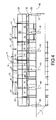
- FIG. 1 is a top plan view of an algae harvesting boat according to the invention
- FIG. 2 is structural framing plan for the boat shown in FIG. 1 ;
- FIGS. 3A and 3B are front and rear views of the boat shown in FIG. 1 ;
- FIG. 4 is a side view of the boat shown in FIG. 1 ;
- FIG. 5A is a side elevational view of the boat shown in FIG. 1 ;
- FIGS. 5B, 5C are perspective views of the boat shown in FIG. 5 ;
- FIG. 6 is a front left perspective view of the boat shown in FIG. 1 ;
- FIG. 7 is a top plan view of the process channel of the boat shown in FIG. 1 ;
- FIG. 8 is an end elevational view of the process channel shown in FIG. 7 ;
- FIG. 9 is a front left perspective view of the process channel shown in FIG. 7 ;
- FIG. 10 is a front left perspective view of a boat of another aspect of the present disclosure.
- FIG. 11 is a front end elevational view of the boat of FIG. 10 ;
- FIG. 12 is a rear end elevational view of the boat of FIG. 10 ;
- FIG. 13 is a diagram of a prior art dissolved air flotation system.
- an algae harvesting boat includes two aluminum members which according to several aspects define pontoons 1 (having exemplary dimensions of 48′′ diameter ⁇ 40′ long) thereby providing flotation members supporting a non-skid deck on an aluminum frame 2 .
- a 48′′ wide process channel 3 having multiple individual channel sections is defined by and positioned between the pontoons 1 .
- Mounted on the deck are a generator unit 4 , an electrical distribution panel 5 , a saturator 6 , a DAF pump 7 , a DAF air compressor 8 , a vacuum pump 9 , multiple algae storage tanks 10 individually receiving material from one of the multiple channel sections, 4′′ butterfly valves 11 and oxygenation spray nozzles 12 .
- the structural framing for the boat includes the two aluminum pontoons 1 , the aluminum structural beam framing 2 , and the 48′′ wide process channel 3 .
- Welded deck framing 14 and aluminum channel framing 16 are also provided.
- front and rear views respectively of the boat include the two aluminum pontoons 1 , 24′′ welded riser sections 18 , 12′′ aluminum beam framing 20 , 12′′ deck with integral framing 22 , a 42′′ safety handrail 24 , a 48′′ tall by 96′′ wide trash guard 26 at an inlet of the process channel 3 , the generator unit 4 , the saturator 6 , the DAF pump 7 , the DAF air compressor 8 , the vacuum pump 9 , a submersible fountain pump 28 , the 4′′ butterfly valves 11 , the algae storage tank 10 , the multiple oxygenation spray nozzles 12 .
- the trash guard 26 is positioned at the forward end of the process channel 3 and at least partially below a water level 30 to permit entrance of the water containing the algae, but to block large elements from entering the process channel 3 .
- the boat includes the aluminum pontoons 1 , the 24′′ welded riser sections 18 , the 12′′ aluminum beam framing 20 , the 12′′ deck with integral framing 22 , the 42′′ safety handrail 24 , the vacuum pump 9 , the multiple 4′′ butterfly valves 11 , the algae storage tanks 10 , and the oxygenation spray nozzles 12 .
- side elevational and sectional views of the boat include the two aluminum pontoons 1 , the 24′′ welded riser sections 18 , the 12′′ aluminum beam framing 20 , the 12′′ deck with integral framing 22 , the 42′′ safety handrail 24 , the 48′′ wide by 96′′ long process channel sections 3 a , 3 b , 3 c , 3 d , the trash guard 26 , the generator unit 4 , the electrical distribution panel 5 , the saturator 6 , the DAF pump 7 , the DAF air compressor 8 , the submersible fountain pump 28 , the oxygenation spray nozzles 12 , the vacuum pump 9 , the algae storage tanks 10 , and the water level 30 .
- FIG. 6 in a perspective view of the boat shown are the two aluminum pontoons 1 , the 24′′ welded riser sections 18 , 12′′ the aluminum beam framing 20 , the 12′′ deck with integral framing 22 , the 42′′ safety handrail 24 , the trash guard 26 , the generator unit 4 , the electrical distribution panel 5 , the saturator 6 , the DAF pump 7 , the DAF air compressor 8 , the 4′′ butterfly valves 11 , the algae storage tanks 10 , and oxygenation spray nozzles 12 .
- the process channel includes 1 ⁇ 2′′ thick (48′′ ⁇ 96′′) solid vinyl sheeting 32 , a plurality of 2′′ SCH80 piping supports 34 , a 1′′ thick (48′′ ⁇ 96′′) solid vinyl baffle 36 , a gap 37 adjacent the solid vinyl baffle 36 , multiple sections of 1′′ SCH80 diffused air piping 38 , multiple 1 ⁇ 2′′ thick (24′′ ⁇ 48′′) deflector plates 40 , multiple 1 ⁇ 2′′ thick (24′′ ⁇ 48′′) algae scum beaches 42 , and a 12′′ ⁇ 12′′ ⁇ 48′′ solid vinyl scum trough 44 .
- the process channel 3 includes the solid vinyl sheeting 32 , the piping supports 34 , the solid vinyl baffle 36 , the diffused air piping 38 , the deflector plates 40 , the algae scum beach 42 , and the solid vinyl scum trough 44 .
- the process channel including the solid vinyl sheeting 32 , the 2′′ SCH80 piping supports 34 , the solid vinyl baffle 36 , the diffused air piping 38 , the deflector plates 40 , the algae scum beach 42 , and the solid vinyl scum trough 44 .
- an algae harvesting boat 50 is modified from the algae harvesting boat of FIG. 1 to include two rectangular-shaped aluminum members which according to several aspects define pontoons 52 , 54 (having exemplary dimensions of 48′′ wide ⁇ 48′′ high ⁇ 40′ long) which are used in place of the pontoons 1 of FIG. 1 .
- the pontoons 52 , 54 provide flat upper surfaces for attachment of the components of the system.
- Other components of algae harvesting boat 50 are substantially the same as the algae harvesting boat of FIG. 1 .
- the pontoons 52 , 54 provide flotation members supporting a non-skid deck on the aluminum frame 2 ′.
- the 48′′ wide process channel 3 ′ having multiple individual channel sections is defined by and is positioned between the pontoons 52 , 54 .
- Mounted on the deck are the generator unit 4 ′, the electrical distribution panel 5 ′, the saturator 6 ′, the DAF pump 7 ′, the DAF air compressor 8 ′, the vacuum pump 9 ′, multiple algae storage tanks 10 ′ individually receiving material from one of the multiple channel sections, the multiple 4′′ butterfly valves 11 ′ and the multiple oxygenation spray nozzles 12 ′.
- the trash guard 26 ′ is similarly located at the forward end of the process channel 3 ′.
- the rectangular-shaped pontoons 53 , 54 provide opposed, planar surfaces 56 , 58 which are substantially parallel to each other.
- the surfaces 56 , 58 define the inner flow and boundary surfaces of the process channel 3 ′ such that additional framing and components are not required to establish the boundary surfaces of the process channel 3 ′ which may be required with the round pontoons 1 of the embodiment of FIG. 1 .
- the flat upward facing surfaces of the pontoons 52 , 54 also provide for direct connection of the support structure of the aluminum frame 2 ′.
- Example embodiments are provided so that this disclosure will be thorough, and will fully convey the scope to those who are skilled in the art. Numerous specific details are set forth such as examples of specific components, devices, and methods, to provide a thorough understanding of embodiments of the present disclosure. It will be apparent to those skilled in the art that specific details need not be employed, that example embodiments may be embodied in many different forms and that neither should be construed to limit the scope of the disclosure. In some example embodiments, well-known processes, well-known device structures, and well-known technologies are not described in detail.
- first, second, third, etc. may be used herein to describe various elements, components, regions, layers and/or sections, these elements, components, regions, layers and/or sections should not be limited by these terms. These terms may be only used to distinguish one element, component, region, layer or section from another region, layer or section. Terms such as “first,” “second,” and other numerical terms when used herein do not imply a sequence or order unless clearly indicated by the context. Thus, a first element, component, region, layer or section discussed below could be termed a second element, component, region, layer or section without departing from the teachings of the example embodiments.
- Spatially relative terms such as “inner,” “outer,” “beneath,” “below,” “lower,” “above,” “upper,” and the like, may be used herein for ease of description to describe one element or feature's relationship to another element(s) or feature(s) as illustrated in the figures. Spatially relative terms may be intended to encompass different orientations of the device in use or operation in addition to the orientation depicted in the figures. For example, if the device in the figures is turned over, elements described as “below” or “beneath” other elements or features would then be oriented “above” the other elements or features. Thus, the example term “below” can encompass both an orientation of above and below. The device may be otherwise oriented (rotated 90 degrees or at other orientations) and the spatially relative descriptors used herein interpreted accordingly.
Landscapes
- Engineering & Computer Science (AREA)
- Life Sciences & Earth Sciences (AREA)
- Health & Medical Sciences (AREA)
- Chemical & Material Sciences (AREA)
- Organic Chemistry (AREA)
- Bioinformatics & Cheminformatics (AREA)
- Wood Science & Technology (AREA)
- Zoology (AREA)
- Biotechnology (AREA)
- General Engineering & Computer Science (AREA)
- Genetics & Genomics (AREA)
- Microbiology (AREA)
- Biochemistry (AREA)
- General Health & Medical Sciences (AREA)
- Sustainable Development (AREA)
- Biomedical Technology (AREA)
- Environmental & Geological Engineering (AREA)
- Mechanical Engineering (AREA)
- Clinical Laboratory Science (AREA)
- Molecular Biology (AREA)
- Environmental Sciences (AREA)
- Marine Sciences & Fisheries (AREA)
- Combustion & Propulsion (AREA)
- Ocean & Marine Engineering (AREA)
- Hydrology & Water Resources (AREA)
- Water Supply & Treatment (AREA)
- Structural Engineering (AREA)
- Civil Engineering (AREA)
- Public Health (AREA)
- Agronomy & Crop Science (AREA)
- Oil, Petroleum & Natural Gas (AREA)
- Physical Water Treatments (AREA)
- Fluid Mechanics (AREA)
- Physics & Mathematics (AREA)
Abstract
An apparatus for harvesting algae from an open body of water includes a boat having a pair of spaced apart parallel flotation members and a deck disposed on and connected to the members. The spaced apart members define an area therebetween forming a process channel. A separating mechanism disposed on the boat separates the process channel into a plurality of process channel sections arranged in series. The process channel sections are disposed intermediate the flotation members. Each of the process channel sections include a deflector plate, a scum beach, a scum trough, and diffused air piping. The diffused air piping is in fluid communication with a dissolved air flotation system.
Description
This application claims the benefit of U.S. Provisional Application No. 61/903,481, filed on Nov. 13, 2013. The entire disclosure of the above application is incorporated herein by reference.
This invention relates to water treatment by dissolved air floatation and, more particularly, harvesting algae from an open body of water utilizing dissolved air floatation technology.
This section provides background information related to the present disclosure which is not necessarily prior art.
Dissolved air flotation (DAF) is a water treatment process that clarifies wastewaters (or other waters) by the removal of suspended matter such as oil or solids. The removal is achieved by dissolving air in the water or wastewater under pressure and then releasing the air at atmospheric pressure in a flotation tank or basin. The released air forms tiny bubbles which adhere to the suspended matter causing the suspended matter to float to the surface of the water where it may then be removed by a skimming device.
Dissolved air flotation is very widely used in treating the industrial wastewater effluents from oil refineries, petrochemical and chemical plants, natural gas processing plants, paper mills, general water treatment and similar industrial facilities. A very similar process known as induced gas flotation is also used for wastewater treatment. Froth flotation is commonly used in the processing of mineral ores.
The feed water to the DAF float tank is often (but not always) dosed with a coagulant (such as ferric chloride or aluminum sulfate) to flocculate the suspended matter.
A portion of the clarified effluent water leaving the DAF tank is pumped into a small pressure vessel (called the air drum) into which compressed air is also introduced. This results in saturating the pressurized effluent water with air. The air-saturated water stream is recycled to the front of the float tank and flows through a pressure reduction valve just as it enters the front of the float tank, which results in the air being released in the form of tiny bubbles. The bubbles adhere to the suspended matter, causing the suspended matter to float to the surface and form a froth layer which is then removed by a skimmer. The froth-free water exits the float tank as the clarified effluent from the DAF unit.
Some DAF unit designs utilize parallel plate packing material, lamellas, to provide more separation surface and therefore to enhance the separation efficiency of the unit.
DAF systems can be categorized as circular (more efficient) and rectangular (more residence time). The former type requires just 3 minutes; an example is a Wock-Oliver DAF system (www.wockoliver.com). The rectangular type requires 20 to 30 minutes; a typical example is a Syskill DAF system (www.syskill.com.au). One of the bigger advantages of the circular type is its spiral scoop. A typical DAF system is shown in the schematic diagram of FIG. 13 .
The DAF Corporation (www.dafcorp.com) FC Maximizer clarifier is designed and manufactured for harvesting algae. It is a hybrid DAF clarifier. Algae feeds on carbon dioxide and sun light. Algae's biomass once refined can be used for animal feed or its lipid oil for blended petroleum based fuels. The FC Maximizer clarifier is a cost-effective way to harvest algae. It can also feed algae. Part of the FC Maximizer clarifier system is the AMT air dissolving system. It can be used to nourish algae with a side stream of CO2 as a nutrient. This side stream of carbon dioxide with laden water and compressed air from this AMT is injected into the FC Maximizer clarifier as fine micron bubbles. These micron bubbles rise to the surface of the water in the tank at a rate 10″ to 12″ per minute. Hundreds of millions of all equal sized, fine micron bubbles entrap themselves in the suspended solids or algae bloom in the FC Maximizer tank.
Parallel with this process, on the open tank top rim is a rotating stainless steel tank carriage that supports the fixed and rotating tank internal parts. A stainless steel, variable speed, two blade rotating scoop is attached to it. Again, this design gently dips and scoops up the dense fine float mat and discharges it into a holding tank. Clean carbon dioxide enriched nutrient water is discharged from the clarifier tank. This water can be piped back into different systems for a multitude of uses.
The FC Maximizer clarifier is self-cleaning. It operates with minimal turbulence in a shallow round tank. The FC Maximizer clarifier will remove 98% of the algae bloom and lipid oil within the first two and a half minutes. The clarifier's wetted parts are all stainless steel. Sizes ranging from 20 gpm up to 9000 gpm are manufactured.
However, the prior art does not directly remove algae from open bodies of water on an in-lake basis utilizing dissolved air floatation technology.
According to the present invention, the dissolved air floatation (DAF) equipment is mounted on a boat (catamaran or barge configuration) to remove microscopic algae directly from the water in lakes and ponds. One key element in the process is the utilization of DAF equipment. The lake water passes through a channel under the boat that allows for the processing of large volumes of water at low energy costs.
The boat would collect both algae and phosphorus by using the dissolved air flotation (DAF) technology. DAF uses tiny bubbles to cause algae to float to the surface of the water. The algae then would be skimmed and stored on the harvesting boat. By weight, 3 percent of algae is phosphorous. Therefore, if 100 pounds of algae were removed, three pounds of phosphorus also would be taken out of the body of water.
The collected algae would be conveyed to a storage facility for processing and/or transport. The algae can be used as a renewable biofuel in several forms. After processing of the algae for its biofuel value, the nutrient rich algal biomass can be used as a sellable, organic product.
An apparatus for harvesting algae from an open body of water includes a boat having a pair of spaced apart parallel flotation members and a deck disposed on and connected to the members. The spaced apart members define an area therebetween forming a process channel. A separating mechanism disposed on the boat separates the process channel into a plurality of process channel sections arranged in series. The process channel sections are disposed intermediate the flotation members. Each of the process channel sections include a deflector plate, a scum beach, a scum trough, and diffused air piping. The diffused air piping is in fluid communication with a dissolved air flotation system.
The above as well as other advantages of the present invention will become readily apparent to those skilled in the art from the following detailed description of a preferred embodiment when considered in the light of the accompanying drawings in which:
The following detailed description and appended drawings describe and illustrate various exemplary embodiments of the invention. The description and drawings serve to enable one skilled in the art to make and use the invention, and are not intended to limit the scope of the invention in any manner. In respect of the methods disclosed, the steps presented are exemplary in nature, and thus, the order of the steps is not necessary or critical.
Referring to FIG. 1 , an algae harvesting boat includes two aluminum members which according to several aspects define pontoons 1 (having exemplary dimensions of 48″ diameter×40′ long) thereby providing flotation members supporting a non-skid deck on an aluminum frame 2. A 48″ wide process channel 3 having multiple individual channel sections is defined by and positioned between the pontoons 1. Mounted on the deck are a generator unit 4, an electrical distribution panel 5, a saturator 6, a DAF pump 7, a DAF air compressor 8, a vacuum pump 9, multiple algae storage tanks 10 individually receiving material from one of the multiple channel sections, 4″ butterfly valves 11 and oxygenation spray nozzles 12.
Referring to FIG. 2 , the structural framing for the boat includes the two aluminum pontoons 1, the aluminum structural beam framing 2, and the 48″ wide process channel 3. Welded deck framing 14 and aluminum channel framing 16 are also provided.
Referring to FIGS. 3A and 3B , front and rear views respectively of the boat include the two aluminum pontoons 1, 24″ welded riser sections 18, 12″ aluminum beam framing 20, 12″ deck with integral framing 22, a 42″ safety handrail 24, a 48″ tall by 96″ wide trash guard 26 at an inlet of the process channel 3, the generator unit 4, the saturator 6, the DAF pump 7, the DAF air compressor 8, the vacuum pump 9, a submersible fountain pump 28, the 4″ butterfly valves 11, the algae storage tank 10, the multiple oxygenation spray nozzles 12. The trash guard 26 is positioned at the forward end of the process channel 3 and at least partially below a water level 30 to permit entrance of the water containing the algae, but to block large elements from entering the process channel 3.
Referring to FIG. 4 , the boat includes the aluminum pontoons 1, the 24″ welded riser sections 18, the 12″ aluminum beam framing 20, the 12″ deck with integral framing 22, the 42″ safety handrail 24, the vacuum pump 9, the multiple 4″ butterfly valves 11, the algae storage tanks 10, and the oxygenation spray nozzles 12.
Referring to FIGS. 5A-5C , side elevational and sectional views of the boat include the two aluminum pontoons 1, the 24″ welded riser sections 18, the 12″ aluminum beam framing 20, the 12″ deck with integral framing 22, the 42″ safety handrail 24, the 48″ wide by 96″ long process channel sections 3 a, 3 b, 3 c, 3 d, the trash guard 26, the generator unit 4, the electrical distribution panel 5, the saturator 6, the DAF pump 7, the DAF air compressor 8, the submersible fountain pump 28, the oxygenation spray nozzles 12, the vacuum pump 9, the algae storage tanks 10, and the water level 30.
Referring to FIG. 6 , in a perspective view of the boat shown are the two aluminum pontoons 1, the 24″ welded riser sections 18, 12″ the aluminum beam framing 20, the 12″ deck with integral framing 22, the 42″ safety handrail 24, the trash guard 26, the generator unit 4, the electrical distribution panel 5, the saturator 6, the DAF pump 7, the DAF air compressor 8, the 4″ butterfly valves 11, the algae storage tanks 10, and oxygenation spray nozzles 12.
Referring to FIG. 7 , the process channel includes ½″ thick (48″×96″) solid vinyl sheeting 32, a plurality of 2″ SCH80 piping supports 34, a 1″ thick (48″×96″) solid vinyl baffle 36, a gap 37 adjacent the solid vinyl baffle 36, multiple sections of 1″ SCH80 diffused air piping 38, multiple ½″ thick (24″×48″) deflector plates 40, multiple ½″ thick (24″×48″) algae scum beaches 42, and a 12″×12″×48″ solid vinyl scum trough 44.
Referring to FIG. 8 , the process channel 3 includes the solid vinyl sheeting 32, the piping supports 34, the solid vinyl baffle 36, the diffused air piping 38, the deflector plates 40, the algae scum beach 42, and the solid vinyl scum trough 44.
Referring to FIG. 9 , the process channel including the solid vinyl sheeting 32, the 2″ SCH80 piping supports 34, the solid vinyl baffle 36, the diffused air piping 38, the deflector plates 40, the algae scum beach 42, and the solid vinyl scum trough 44.
Referring to FIGS. 10-12 , an algae harvesting boat 50 is modified from the algae harvesting boat of FIG. 1 to include two rectangular-shaped aluminum members which according to several aspects define pontoons 52, 54 (having exemplary dimensions of 48″ wide×48″ high ×40′ long) which are used in place of the pontoons 1 of FIG. 1 . The pontoons 52, 54 provide flat upper surfaces for attachment of the components of the system. Other components of algae harvesting boat 50 are substantially the same as the algae harvesting boat of FIG. 1 . The pontoons 52, 54 provide flotation members supporting a non-skid deck on the aluminum frame 2′. The 48″ wide process channel 3′ having multiple individual channel sections is defined by and is positioned between the pontoons 52, 54. Mounted on the deck are the generator unit 4′, the electrical distribution panel 5′, the saturator 6′, the DAF pump 7′, the DAF air compressor 8′, the vacuum pump 9′, multiple algae storage tanks 10′ individually receiving material from one of the multiple channel sections, the multiple 4″ butterfly valves 11′ and the multiple oxygenation spray nozzles 12′. The trash guard 26′ is similarly located at the forward end of the process channel 3′.
With specific reference to FIG. 12 the rectangular-shaped pontoons 53, 54 provide opposed, planar surfaces 56, 58 which are substantially parallel to each other. The surfaces 56, 58 define the inner flow and boundary surfaces of the process channel 3′ such that additional framing and components are not required to establish the boundary surfaces of the process channel 3′ which may be required with the round pontoons 1 of the embodiment of FIG. 1 . The flat upward facing surfaces of the pontoons 52, 54 also provide for direct connection of the support structure of the aluminum frame 2′.
In accordance with the provisions of the patent statutes, the present invention has been described in what is considered to represent its preferred embodiment. However, it should be noted that the invention can be practiced otherwise than as specifically illustrated and described without departing from its spirit or scope.
Example embodiments are provided so that this disclosure will be thorough, and will fully convey the scope to those who are skilled in the art. Numerous specific details are set forth such as examples of specific components, devices, and methods, to provide a thorough understanding of embodiments of the present disclosure. It will be apparent to those skilled in the art that specific details need not be employed, that example embodiments may be embodied in many different forms and that neither should be construed to limit the scope of the disclosure. In some example embodiments, well-known processes, well-known device structures, and well-known technologies are not described in detail.
The terminology used herein is for the purpose of describing particular example embodiments only and is not intended to be limiting. As used herein, the singular forms “a,” “an,” and “the” may be intended to include the plural forms as well, unless the context clearly indicates otherwise. The terms “comprises,” “comprising,” “including,” and “having,” are inclusive and therefore specify the presence of stated features, integers, steps, operations, elements, and/or components, but do not preclude the presence or addition of one or more other features, integers, steps, operations, elements, components, and/or groups thereof. The method steps, processes, and operations described herein are not to be construed as necessarily requiring their performance in the particular order discussed or illustrated, unless specifically identified as an order of performance. It is also to be understood that additional or alternative steps may be employed.
When an element or layer is referred to as being “on,” “engaged to,” “connected to,” or “coupled to” another element or layer, it may be directly on, engaged, connected or coupled to the other element or layer, or intervening elements or layers may be present. In contrast, when an element is referred to as being “directly on,” “directly engaged to,” “directly connected to,” or “directly coupled to” another element or layer, there may be no intervening elements or layers present. Other words used to describe the relationship between elements should be interpreted in a like fashion (e.g., “between” versus “directly between,” “adjacent” versus “directly adjacent,” etc.). As used herein, the term “and/or” includes any and all combinations of one or more of the associated listed items.
Although the terms first, second, third, etc. may be used herein to describe various elements, components, regions, layers and/or sections, these elements, components, regions, layers and/or sections should not be limited by these terms. These terms may be only used to distinguish one element, component, region, layer or section from another region, layer or section. Terms such as “first,” “second,” and other numerical terms when used herein do not imply a sequence or order unless clearly indicated by the context. Thus, a first element, component, region, layer or section discussed below could be termed a second element, component, region, layer or section without departing from the teachings of the example embodiments.
Spatially relative terms, such as “inner,” “outer,” “beneath,” “below,” “lower,” “above,” “upper,” and the like, may be used herein for ease of description to describe one element or feature's relationship to another element(s) or feature(s) as illustrated in the figures. Spatially relative terms may be intended to encompass different orientations of the device in use or operation in addition to the orientation depicted in the figures. For example, if the device in the figures is turned over, elements described as “below” or “beneath” other elements or features would then be oriented “above” the other elements or features. Thus, the example term “below” can encompass both an orientation of above and below. The device may be otherwise oriented (rotated 90 degrees or at other orientations) and the spatially relative descriptors used herein interpreted accordingly.
Claims (17)
1. An apparatus for harvesting algae from an open body of water, comprising:
a boat having a pair of spaced apart parallel flotation members and a deck disposed on and connected to the members, the spaced apart members defining an area therebetween forming a process channel; and
a separating mechanism disposed on the boat separating the process channel into a plurality of process channel sections arranged in series, the process channel sections disposed intermediate the flotation members, each of the process channel sections including at least one deflector plate below a water level, an algae scum beach crossing the water level, a scum trough coupled to the algae scum beach, and a diffused air piping, with the diffused air piping in fluid communication with a dissolved air flotation system.
2. The apparatus for harvesting algae from an open body of water of claim 1 , further including a generator unit and an electrical distribution panel mounted on the deck, the generator unit operating to energize a saturator, a dissolved air flotation (DAF) pump, a DAF air compressor, and a vacuum pump.
3. The apparatus for harvesting algae from an open body of water of claim 1 , further including a plurality of algae storage tanks mounted on the deck each collecting algae from one of the process channel sections.
4. The apparatus for harvesting algae from an open body of water of claim 1 , wherein the spaced apart members comprise substantially flat walls, the walls acting to contain and direct algae received between the walls for feeding to the separating mechanism.
5. The apparatus for harvesting algae from an open body of water of claim 1 , wherein the process channel includes vinyl sheeting defining walls of the process channel, a plurality of piping supports, a baffle, and multiple sections of the diffused air piping.
6. The apparatus for harvesting algae from an open body of water of claim 1 , further including a trash guard at an inlet of the process channel.
7. The apparatus for harvesting algae from an open body of water of claim 1 , further including a saturator, a dissolved air flotation (DAF) pump, a DAF air compressor, a vacuum pump, and multiple algae storage tanks each mounted on the deck.
8. An apparatus for harvesting algae from an open body of water, comprising:
a boat having a pair of spaced apart parallel flotation members and a deck disposed on and connected to the members, the spaced apart members defining an area therebetween forming a process channel; and
a separating mechanism disposed on the boat separating the process channel into a plurality of process channel sections arranged in series, the process channel sections disposed intermediate the flotation members, each of the process channel sections including a deflector plate below a water level, a scum beach crossing the water level, a scum trough coupled to the scum beach, and diffused air piping, with the diffused air piping in fluid communication with a dissolved air flotation system.
9. The apparatus for harvesting algae from an open body of water of claim 8 , further including a generator unit and an electrical distribution panel mounted on the deck, the generator unit operating to energize a saturator, a dissolved air flotation (DAF) pump, a DAF air compressor, and a vacuum pump.
10. The apparatus for harvesting algae from an open body of water of claim 8 , further including a plurality of algae storage tanks mounted on the deck each collecting algae from one of the process channel sections.
11. The apparatus for harvesting algae from an open body of water of claim 8 , wherein the spaced apart members comprise substantially flat walls facing each other, the walls acting to contain and direct algae received between the walls for feeding to the separating mechanism.
12. The apparatus for harvesting algae from an open body of water of claim 8 , wherein the process channel includes vinyl sheeting defining walls of the process channel, a plurality of piping supports, a baffle, and multiple sections of the diffused air piping.
13. The apparatus for harvesting algae from an open body of water of claim 8 , further including a trash guard at an inlet of the process channel.
14. An apparatus for harvesting algae from an open body of water, comprising:
a boat having a pair of spaced apart parallel flotation members, the flotation members defining substantially flat walls, and a deck disposed on and connected to the members, the walls defining an area therebetween forming a process channel through which water containing algae flows; and
a separating mechanism disposed on the boat separating the process channel into a plurality of process channel sections arranged in series, the process channel sections disposed intermediate the flotation members, each of the process channel sections including a deflector plate below a water level, a scum beach crossing the water level, a scum trough coupled to the scum beach, and diffused air piping, with the diffused air piping in fluid communication with a dissolved air flotation system, wherein the walls contain and direct algae received between the walls for feeding to the separating mechanism.
15. The apparatus for harvesting algae from an open body of water of claim 14 , further including mounted on the deck a saturator, a dissolved air flotation (DAF) pump, a DAF air compressor, a vacuum pump, and multiple algae storage tanks.
16. The apparatus for harvesting algae from an open body of water of claim 14 , further including a trash guard positioned at a forward end of the process channel and at least partially below a water level to permit entrance of water containing algae into the process channel, while blocking large elements from entering the process channel.
17. The apparatus for harvesting algae from an open body of water of claim 14 , further including a submersible fountain pump positioned within the process channel.
Priority Applications (1)
| Application Number | Priority Date | Filing Date | Title |
|---|---|---|---|
| US14/540,309 US9809464B2 (en) | 2013-11-13 | 2014-11-13 | Apparatus for harvesting algae from open body of water |
Applications Claiming Priority (2)
| Application Number | Priority Date | Filing Date | Title |
|---|---|---|---|
| US201361903481P | 2013-11-13 | 2013-11-13 | |
| US14/540,309 US9809464B2 (en) | 2013-11-13 | 2014-11-13 | Apparatus for harvesting algae from open body of water |
Publications (2)
| Publication Number | Publication Date |
|---|---|
| US20150128838A1 US20150128838A1 (en) | 2015-05-14 |
| US9809464B2 true US9809464B2 (en) | 2017-11-07 |
Family
ID=53042555
Family Applications (1)
| Application Number | Title | Priority Date | Filing Date |
|---|---|---|---|
| US14/540,309 Active 2035-12-16 US9809464B2 (en) | 2013-11-13 | 2014-11-13 | Apparatus for harvesting algae from open body of water |
Country Status (1)
| Country | Link |
|---|---|
| US (1) | US9809464B2 (en) |
Cited By (2)
| Publication number | Priority date | Publication date | Assignee | Title |
|---|---|---|---|---|
| CN111469990A (en) * | 2020-04-23 | 2020-07-31 | 吕超 | An environmentally friendly river cleaning device based on thermal storage expansion double-layer cleaning |
| US20240375028A1 (en) * | 2021-09-10 | 2024-11-14 | Algaecore Technologies Ltd | Rotary drum filtering machine for algae filtration |
Families Citing this family (10)
| Publication number | Priority date | Publication date | Assignee | Title |
|---|---|---|---|---|
| WO2014159439A1 (en) * | 2013-03-13 | 2014-10-02 | Oney Stephen K | Systems and methods for cultivating and harvesting blue water bioalgae and aquaculture |
| CA3173023A1 (en) * | 2014-07-11 | 2016-01-14 | Xiaoxi Wu | Photobioreactor systems and methods for producing biomass |
| US11566211B2 (en) * | 2014-10-22 | 2023-01-31 | Gsr Solutions, Llc | Systems and methods of producing compositions from the nutrients recovered from waste streams |
| US10900013B2 (en) * | 2014-10-22 | 2021-01-26 | Gsr Solutions, Llc | Systems and methods of producing compositions from the nutrients recovered from waste streams |
| CN107187551B (en) * | 2017-05-30 | 2019-02-01 | 金康 | An automatic cutting conveyor for deep water aquatic plants in environmental water treatment |
| US10689821B1 (en) * | 2019-02-28 | 2020-06-23 | Peter Whittington | Algae skimmer and debris removal system |
| CN113715973A (en) * | 2020-07-27 | 2021-11-30 | 浙江工业大学之江学院 | Robot for collecting garbage on water |
| CN112030919A (en) * | 2020-09-09 | 2020-12-04 | 泉州台商投资区双霞机械设计服务中心 | Amphibious blue algae treatment device for land and lake |
| CN112746602B (en) * | 2020-12-17 | 2022-03-29 | 山东省水利科学研究院 | A water conservancy project algae cleaning collection and processing device |
| US12433213B2 (en) * | 2021-05-14 | 2025-10-07 | Fluor Technologies Corporation | Systems and methods for growing and harvesting seaweed using non-producing offshore platforms |
Citations (18)
| Publication number | Priority date | Publication date | Assignee | Title |
|---|---|---|---|---|
| US4176058A (en) * | 1974-10-24 | 1979-11-27 | Grobler Jacobus J | Method means for de-silting water |
| JPS6073910A (en) | 1983-09-30 | 1985-04-26 | Katsutoshi Oshima | Collecting ship for material suspending under water or floating on surface |
| US4690756A (en) * | 1985-05-15 | 1987-09-01 | Ry Charles D Van | Apparatus for microaquaculture and pollution control |
| US5223130A (en) * | 1989-06-13 | 1993-06-29 | Farm Fish, S.R.L. | Device for organic neutralization and removal of phosphorus compounds present in water basins |
| US20020079270A1 (en) * | 2000-12-27 | 2002-06-27 | Genady Borodyanski | Microalgae separator apparatus and method |
| CN1143826C (en) | 2000-09-18 | 2004-03-31 | 中国科学院生态环境研究中心 | A ship-type air flotation algae removal device and method |
| US7101478B2 (en) * | 2003-09-30 | 2006-09-05 | Aqua&Co S.R.L. | Foam removal device |
| JP2007160178A (en) | 2005-12-12 | 2007-06-28 | Mitsubishi Heavy Ind Ltd | Water area purifying apparatus, aquatic-contamination living organism recovery ship and method for treating aquatic-contamination living organism |
| US7255332B2 (en) * | 2004-05-25 | 2007-08-14 | The Board Of Trustees Of The University Of Arkansas | System and method for dissolving gases in liquids |
| JP2008063823A (en) | 2006-09-07 | 2008-03-21 | Marine Giken:Kk | Floating body device for recovering water-bloom propagation preventive floating material |
| CN201071106Y (en) | 2007-07-06 | 2008-06-11 | 胡建东 | Blue algae pick-up boat with air-float method |
| US7452462B2 (en) * | 2002-07-12 | 2008-11-18 | Ecoceane Sas | Vessel designed to collect waste on board |
| CN101671060A (en) | 2009-09-24 | 2010-03-17 | 同济大学 | Processing device of single air floatation alga removing ship for large-area alga eruption of natural water body and processing method |
| CN101691249B (en) | 2009-09-24 | 2011-06-22 | 同济大学 | Treatment device and treatment method for large-area algal blooms in natural water bodies by combined use of air floatation ship and slag scraper |
| US20120168385A1 (en) | 2009-09-07 | 2012-07-05 | Raymond Anderson | Apparatus and Method for the Treatment of Water |
| US20120228232A1 (en) | 2007-07-31 | 2012-09-13 | Aquafiber Technologies Corp. | Water Remediation and Biosolids Collection System and Associated Methods |
| CN103288160A (en) | 2013-06-14 | 2013-09-11 | 哈尔滨工业大学 | Device for removing algae in eutrophicated water body by mobile floatation platform and application method thereof |
| CN103318983A (en) | 2013-07-17 | 2013-09-25 | 叶建锋 | Micro-air-flotation algae removal device and method for small water body |
-
2014
- 2014-11-13 US US14/540,309 patent/US9809464B2/en active Active
Patent Citations (18)
| Publication number | Priority date | Publication date | Assignee | Title |
|---|---|---|---|---|
| US4176058A (en) * | 1974-10-24 | 1979-11-27 | Grobler Jacobus J | Method means for de-silting water |
| JPS6073910A (en) | 1983-09-30 | 1985-04-26 | Katsutoshi Oshima | Collecting ship for material suspending under water or floating on surface |
| US4690756A (en) * | 1985-05-15 | 1987-09-01 | Ry Charles D Van | Apparatus for microaquaculture and pollution control |
| US5223130A (en) * | 1989-06-13 | 1993-06-29 | Farm Fish, S.R.L. | Device for organic neutralization and removal of phosphorus compounds present in water basins |
| CN1143826C (en) | 2000-09-18 | 2004-03-31 | 中国科学院生态环境研究中心 | A ship-type air flotation algae removal device and method |
| US20020079270A1 (en) * | 2000-12-27 | 2002-06-27 | Genady Borodyanski | Microalgae separator apparatus and method |
| US7452462B2 (en) * | 2002-07-12 | 2008-11-18 | Ecoceane Sas | Vessel designed to collect waste on board |
| US7101478B2 (en) * | 2003-09-30 | 2006-09-05 | Aqua&Co S.R.L. | Foam removal device |
| US7255332B2 (en) * | 2004-05-25 | 2007-08-14 | The Board Of Trustees Of The University Of Arkansas | System and method for dissolving gases in liquids |
| JP2007160178A (en) | 2005-12-12 | 2007-06-28 | Mitsubishi Heavy Ind Ltd | Water area purifying apparatus, aquatic-contamination living organism recovery ship and method for treating aquatic-contamination living organism |
| JP2008063823A (en) | 2006-09-07 | 2008-03-21 | Marine Giken:Kk | Floating body device for recovering water-bloom propagation preventive floating material |
| CN201071106Y (en) | 2007-07-06 | 2008-06-11 | 胡建东 | Blue algae pick-up boat with air-float method |
| US20120228232A1 (en) | 2007-07-31 | 2012-09-13 | Aquafiber Technologies Corp. | Water Remediation and Biosolids Collection System and Associated Methods |
| US20120168385A1 (en) | 2009-09-07 | 2012-07-05 | Raymond Anderson | Apparatus and Method for the Treatment of Water |
| CN101671060A (en) | 2009-09-24 | 2010-03-17 | 同济大学 | Processing device of single air floatation alga removing ship for large-area alga eruption of natural water body and processing method |
| CN101691249B (en) | 2009-09-24 | 2011-06-22 | 同济大学 | Treatment device and treatment method for large-area algal blooms in natural water bodies by combined use of air floatation ship and slag scraper |
| CN103288160A (en) | 2013-06-14 | 2013-09-11 | 哈尔滨工业大学 | Device for removing algae in eutrophicated water body by mobile floatation platform and application method thereof |
| CN103318983A (en) | 2013-07-17 | 2013-09-25 | 叶建锋 | Micro-air-flotation algae removal device and method for small water body |
Non-Patent Citations (1)
| Title |
|---|
| The Daily Standard, William Kincaid, "Official floats idea to build boat that harvest algae," Apr. 1, 2011, Retrieved from Web on Oct. 2, 2013: <http://www.dailystandard.com/archive/2011-04-01/stories/14565/official-floats-idea-to-build-boat-that-harvests-algae>. |
Cited By (4)
| Publication number | Priority date | Publication date | Assignee | Title |
|---|---|---|---|---|
| CN111469990A (en) * | 2020-04-23 | 2020-07-31 | 吕超 | An environmentally friendly river cleaning device based on thermal storage expansion double-layer cleaning |
| CN111469990B (en) * | 2020-04-23 | 2021-02-26 | 吕超 | River course cleaning device based on double-deck gasbag of heat accumulation inflation |
| US20240375028A1 (en) * | 2021-09-10 | 2024-11-14 | Algaecore Technologies Ltd | Rotary drum filtering machine for algae filtration |
| US12544693B2 (en) * | 2021-09-10 | 2026-02-10 | Algaecore Technologies Ltd | Rotary drum filtering machine for algae filtration |
Also Published As
| Publication number | Publication date |
|---|---|
| US20150128838A1 (en) | 2015-05-14 |
Similar Documents
| Publication | Publication Date | Title |
|---|---|---|
| US9809464B2 (en) | Apparatus for harvesting algae from open body of water | |
| US8728318B2 (en) | Settling device, purifier comprising a settling device and methods for anaerobic or aerobic purification of waste water | |
| US7632400B2 (en) | Water treatment equipment | |
| US20170088441A1 (en) | Method and device for deep oil removal from wastewater containing low concentration dirty oil | |
| US11008227B2 (en) | Wastewater purification system | |
| CN102260025B (en) | Biochemical pretreatment process of oily wastewater | |
| US20240327251A1 (en) | Passive gravity filter cell and methods of use thereof | |
| KR20220131710A (en) | Sealed dissolved air flotation separation system and method for removing solid materials including microplastics | |
| CN103241863B (en) | Shipborne water area purifying system and water area purifying method | |
| KR101164660B1 (en) | The dissolved air flotation system with the use of on-site treatment technology for the water quality improvement of reservoir and pond | |
| US6129839A (en) | Separation system for immiscible liquids | |
| CN104209004A (en) | Membrane module for recovering lightweight microscale oil stain in water area | |
| JP4538404B2 (en) | Water purification apparatus, water pollution organism recovery ship, and water pollution organism treatment method | |
| CN201010539Y (en) | Treatment device for waste water containing oil | |
| KR20150002143A (en) | Apparatus for Producing Agricultural Water using Multistage Multicyclone System | |
| CN201517051U (en) | Large-sized industrial sewage oil removal device | |
| CN118084187A (en) | A multifunctional composite aeration membrane bioreactor and sewage treatment method | |
| KR20180068518A (en) | Hybrid water treatment system of new concept wastewater reuse and desalination methods for using low energy | |
| CN216426944U (en) | Oil-water separating device | |
| CN101189053B (en) | water purification device | |
| CN209940650U (en) | A multi-stage sewage oil separation system | |
| CN212050941U (en) | Micro-power oil-water separator | |
| Permana et al. | Design and Construction of Domestic Oil and Fat Waste Processing as a Practical Tool for Practical Application in Waste Processing Technology in the DIII Industrial Chemistry Study Program | |
| KR101993059B1 (en) | Waste water treating system | |
| Colic et al. | Reuse of California brine olive oil processing wastewater to meet zero discharge goal |
Legal Events
| Date | Code | Title | Description |
|---|---|---|---|
| STCF | Information on status: patent grant |
Free format text: PATENTED CASE |
|
| MAFP | Maintenance fee payment |
Free format text: PAYMENT OF MAINTENANCE FEE, 4TH YEAR, MICRO ENTITY (ORIGINAL EVENT CODE: M3551); ENTITY STATUS OF PATENT OWNER: MICROENTITY Year of fee payment: 4 |
|
| MAFP | Maintenance fee payment |
Free format text: PAYMENT OF MAINTENANCE FEE, 8TH YEAR, MICRO ENTITY (ORIGINAL EVENT CODE: M3552); ENTITY STATUS OF PATENT OWNER: MICROENTITY Year of fee payment: 8 |