US9804402B2 - Portable folding virtual reality device - Google Patents
Portable folding virtual reality device Download PDFInfo
- Publication number
- US9804402B2 US9804402B2 US15/057,260 US201615057260A US9804402B2 US 9804402 B2 US9804402 B2 US 9804402B2 US 201615057260 A US201615057260 A US 201615057260A US 9804402 B2 US9804402 B2 US 9804402B2
- Authority
- US
- United States
- Prior art keywords
- cover
- supporting plate
- angle
- lens
- mounting case
- Prior art date
- Legal status (The legal status is an assumption and is not a legal conclusion. Google has not performed a legal analysis and makes no representation as to the accuracy of the status listed.)
- Expired - Fee Related
Links
- 239000010409 thin film Substances 0.000 claims description 7
- 238000004519 manufacturing process Methods 0.000 description 1
- 239000000463 material Substances 0.000 description 1
- 238000000034 method Methods 0.000 description 1
Images


Classifications
-
- G—PHYSICS
- G02—OPTICS
- G02B—OPTICAL ELEMENTS, SYSTEMS OR APPARATUS
- G02B27/00—Optical systems or apparatus not provided for by any of the groups G02B1/00 - G02B26/00, G02B30/00
- G02B27/02—Viewing or reading apparatus
- G02B27/04—Viewing or reading apparatus having collapsible parts
-
- G—PHYSICS
- G02—OPTICS
- G02B—OPTICAL ELEMENTS, SYSTEMS OR APPARATUS
- G02B25/00—Eyepieces; Magnifying glasses
- G02B25/002—Magnifying glasses
-
- G—PHYSICS
- G02—OPTICS
- G02B—OPTICAL ELEMENTS, SYSTEMS OR APPARATUS
- G02B27/00—Optical systems or apparatus not provided for by any of the groups G02B1/00 - G02B26/00, G02B30/00
- G02B27/02—Viewing or reading apparatus
- G02B27/022—Viewing apparatus
- G02B27/027—Viewing apparatus comprising magnifying means
-
- G—PHYSICS
- G02—OPTICS
- G02B—OPTICAL ELEMENTS, SYSTEMS OR APPARATUS
- G02B27/00—Optical systems or apparatus not provided for by any of the groups G02B1/00 - G02B26/00, G02B30/00
- G02B27/02—Viewing or reading apparatus
- G02B27/028—Viewing or reading apparatus characterised by the supporting structure
-
- G—PHYSICS
- G02—OPTICS
- G02B—OPTICAL ELEMENTS, SYSTEMS OR APPARATUS
- G02B27/00—Optical systems or apparatus not provided for by any of the groups G02B1/00 - G02B26/00, G02B30/00
- G02B27/01—Head-up displays
- G02B27/0101—Head-up displays characterised by optical features
- G02B2027/0127—Head-up displays characterised by optical features comprising devices increasing the depth of field
-
- G—PHYSICS
- G02—OPTICS
- G02B—OPTICAL ELEMENTS, SYSTEMS OR APPARATUS
- G02B27/00—Optical systems or apparatus not provided for by any of the groups G02B1/00 - G02B26/00, G02B30/00
- G02B27/01—Head-up displays
- G02B27/017—Head mounted
- G02B2027/0178—Eyeglass type
-
- G—PHYSICS
- G02—OPTICS
- G02B—OPTICAL ELEMENTS, SYSTEMS OR APPARATUS
- G02B27/00—Optical systems or apparatus not provided for by any of the groups G02B1/00 - G02B26/00, G02B30/00
- G02B27/01—Head-up displays
- G02B27/017—Head mounted
- G02B27/0172—Head mounted characterised by optical features
-
- G—PHYSICS
- G02—OPTICS
- G02B—OPTICAL ELEMENTS, SYSTEMS OR APPARATUS
- G02B27/00—Optical systems or apparatus not provided for by any of the groups G02B1/00 - G02B26/00, G02B30/00
- G02B27/01—Head-up displays
- G02B27/017—Head mounted
- G02B27/0176—Head mounted characterised by mechanical features
Definitions
- This invention relates to a structure of a portable folding virtual reality device of which the weight and volume can be reduced greatly provided with a smart phone.
- the conventional VR device as shown in FIG. 5( a ) , is provided with a smart phone therein as a box type for a lens case corresponding to a focus distance of a lens, and it increases the volume thereof not to be portable.
- Some of the disclosed conventional 3D observing mirrors are not provided with smart phones and are limited in just devices that can observe simple pictures or photos and thus they are impossible to be applied to virtual reality devices.
- the VR image such as the invention, as shown in FIGS. 1 and 3 is shaped to be fixed to a head of a user as a band and thus when it is heavy and has large volume, it is impossible to use the device and even if used, it is very inconvenient.
- the object of the present invention relates to a portable folding virtual reality device which has small volume and is light, and in which the focus distance of the magnifying lens is fixed and the observing image can be controlled from the outsides.
- a portable folding virtual reality device of the present invention may include: a cover 2 formed horizontally;
- a mounting case 1 which is provided on a front of the cover 2 and on which an image device such as a smart phone is mounted; a lens plate 4 provided with a magnifying lens 5 at a rear of the cover 2 ; and a band 8 which is connected to both ends of the lens plate 4 and through which the device is mounted to a head of a user
- the mounting case 1 and the lens plate 4 are arranged to form up and downward at a right angle and to rotate by the cover 2 and a front and rear hinges, a supporting plate 3 that rotates left and rightward with respect to a central line of the cover 2 is further provided, and the interval between the front hinge and the rear hinge is identical to the focal distance of the left and right magnifying lens ( 5 ) such that the mounting case 1 and the lens plate 4 are arranged to form a right angle with respect to the cover 2 by the supporting plate 3 and thus the focal distance of the magnifying lens 5 is matched automatically to the image on the mounting case 1 when used and further is folded as a thin film structure when carried.
- a first angle supporting plate 1 a may be provided on an upper surface of the mounting case 1
- a second angle supporting plate 2 a may be provided on a front surface of the cover 2
- a third angle supporting plate 2 b may be provided on a rear surface of the cover 2
- a fourth angle supporting plate 4 a may be provided on an upper part of the lens plate 4 wherein the angle of each angle supporting plate 1 a , 2 a , 2 b , 4 a is 0-90° such that the mounting case 1 and a front surface of the cover 2 are arranged to form a right angle and the rear surface of the cover 2 and the lens plate 4 are arranged to form a right angle when used and thus the focal distance of the magnifying lens 5 corresponds automatically to a surface of the smart phone 100 .
- the interval between the front hinge 6 and the rear hinge 7 which are provided below the cover 2 may be identical to the focal distance of the magnifying lens 5 .
- Both ends of the mounting case 1 may be opened such that the image on the mounting case is controlled by touching the image without an additional controller for the image.
- the rotation angle of the front hinge and rear hinges may be 90-180° and the interval between the front hinge 6 and the rear hinge 7 , which are provided below the cover 2 may correspond to the focal distance of the magnifying lens 5 .
- FIG. 1 is a view of a structure of a portable folding virtual reality device according to the present invention
- FIG. 2 is a side view of a portable folding virtual reality device according to the present invention.
- FIG. 3 is a view of a portable folding virtual reality device when used, according to the present invention.
- FIGS. 4A and 4B are views of a portable folding virtual reality device which is folded when carried, according to the present invention.
- FIGS. 5A and 5B are views of comparing a portable folding virtual reality device according to the present invention to a conventional device in size;
- FIG. 6 is a view of a portable folding virtual reality device according to a first embodiment of the present invention.
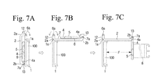
- FIG. 7A is a view of a portable folding virtual reality device when carried according to a first embodiment of the present invention.
- FIG. 7B is a view of a portable folding virtual reality device when deployed and operated according to a first embodiment of the present invention.
- FIG. 7C is a view of a portable folding virtual reality device when deployed according to a first embodiment of the present invention.
- FIG. 8 is a view of is a view of a portable folding virtual reality device when it is applied to a smart phone according to a first embodiment of the present invention.
- the portable folding virtual reality device can be thin film structure when carried, the focal distance of the magnifying lens is equally stabilized when used, and can be provided with a structure for a smart phone, on which an image device such as smart phone can be arranged, which is provided with a gyro device and a location tracing device in which a mobile image and the image are varied in accordance with the view angles of up down and left rightward.
- the portable folding virtual reality device is provided with: a mounting case 1 on which an image device such as a smart phone is arranged; a cover 2 that consists the upper part together with a hinge 6 on the upper rear part of the mounting case 1 : a lens plate 4 connected to a hinge 7 on the rear part of the cover 2 ; magnifying lens 5 provided at the left and right of the lens plate 4 ; and a band 8 which is provided at the left and right of the lens plate 4 and used for mounting the portable folding virtual reality device to his/her head by a user.
- the lens plate 4 and the mounting case 1 are arranged at a right angle based on their central lines when used, and a supporting plate 3 is provided, which is rotated along a central line of the cover 2 by a supporting plate hinge 10 at a center of the cover when carried, as shown in FIG. 1 .
- the image device mounted as described above needs to be exposed at left and right, the image on which can be controlled from outsides.
- a front hinge 6 and the rear hinge 7 are provided on front and rear surfaces of a main body cover 4 , respectively wherein the mounting case 1 is folded to a direction of the cover 2 at a right angle through the front hinge 6 and the lens plate 4 is folded to a direction of the cover 2 at a right angle through the rear hinge 7 .
- the supporting plate 3 is connected to a hinge 10 along a central line of the cover 2 .
- a smart phone or a tablet personal computer the size of which is similar to that of the smart phone may be mounted on the mounting case 1 .
- the distance between the front hinge 6 and the rear hinge 7 inside the cover 2 corresponds to the focal distance of the magnifying lens 5 such that a viewer 11 may observe the image on a smart phone mounted on the mounting case 1 through the magnifying lens 5 with the corresponding focal distance of the magnifying lens 5 .
- the mounting case 1 and the lens plate 4 are arranged in parallel on front and rear surfaces based on the supporting plate 3 when used wherein the mounting case 1 and the lens plate 4 are at a right angle with respect to the supporting plate 3 .
- the focal distance of the magnifying lens 5 corresponds to the image on the surface of the smart phone mounted on the mounting case 1 .
- the mounting case 1 on which a smart phone is mounted is unfolded from the cover 2 to be a right angle up and downward and then the lens plate 4 is unfolded to be a right angle up and downward with respect to the cover 2 .
- the supporting plate 3 rotates at 90° left and rightward around the cover 2 to support the part between the mounting case 1 and the lens plate 4 thereby to keep the mounting case 1 and the lens plate 4 be parallel.
- the band 8 is provided at both ends of the lens plate 4 to be mounted on a head of a user.
- the distance between the front hinge 6 arranged on a front of the cover 2 and the rear hinge 7 arranged on a rear of the cover 2 is kept to correspond to the focal distance of the magnifying lens 5 by the supporting plate 3 such that the left and right magnifying lens 5 on the lens plate 4 is fixed stably with respect to the image on the smart phone of the mounting case thereby to observe a stable virtual reality image.
- the front hinge 6 for connecting the cover 2 and the mounting case 1 is configured such that one end is formed as a circular ball 61 and the other end is formed as a circular band 62 wherein the circular band 62 is curved at 180° or more, preferably at 180-200° so that the circular band 62 is not separated from the circular ball 61 .
- the rear hinge for connecting the cover 2 and the lens plate 4 is also configured such that one end is formed as a circular ball and the other end is formed as a circular band, like the front hinge 6 , wherein the circular band 62 is curved at 180° or more, preferably at 180-200°.
- the front and rear hinges 6 , 7 are manufactured by drawing material in a long size, like a pipe process, and then cutting it in a desired size to be assembled simple, and thus it is proper for a hinge structure of thin film and reduces manufacturing cost.
- the structure of the hinges is not limited thereto and other hinge structures such as a hinge for eyeglass may be applied for the structure.
- the supporting plate 3 is hinged on the cover 2 , and the lens plate 4 , the mounting case 1 and the band 8 are folded to form a thin film structure and kept simply in a keeping case 9 .
- the VR device is seated on a head of a user using the band 8 , as shown in FIG. 3 , it has to be light and have small volume.
- the technical task of the invention is about how small the volume of the portable folding virtual reality device is and how light weight it is and whether the focal distance of the magnifying lens is stably fixed.
- the conventional VR device has volume of 2380 cm 2 with 14 cm ⁇ 17 cm ⁇ 10 cm in length, width, height and weight of 440 g but under the present invention, the volume is 326 cm 2 with 14.5 cm ⁇ 7.5 cm ⁇ 3 cm in length, width, height and has weight of below 60 g. That is, the weight and volume is reduced by 1 ⁇ 4 ⁇ 1 ⁇ 6 compared to the conventional device, which is convenient in carrying. Therefore, the conventional existing VR devices are inconvenient in carrying but the invention is simply portable.
- the image device such as a smart phone is embedded therein such that the surface of the smart phone is covered, making it impossible to control the image.
- the both surface of a smart phone which is mounted on the mounting case 1 are exposed to control the image on the smart phone without an additional control device for the image.
- the portable folding virtual reality device of the preset invention is structured as followings.
- a first hinge 1 b that is protruded to an upper central part of a mounting case 1 is provided
- a second hinge 4 b that is protruded to an upper central part of the lens plate 4 is provided
- a first protrusion plate 12 is provided on a front of the cover 2
- a second protrusion plate 13 is provided on a rear of the cover 2 .
- a first angel supporting plate 1 a is provided at an oblique angle of 45° to an upper horizontal direction of the mounting case 1 and a second angle supporting plate 2 b is provided at an oblique angle of 45° on a front of the cover 2 .
- a third angle supporting plate 2 b is provided at an oblique angle of 45° on a lower part of the second protrusion plate 13 below the rear of the cover 2 and a fourth angle supporting plate 4 a is provided at an oblique angle of 45° to an upper horizontal direction of the lens plate 4 .
- the lengths of the front and rear surfaces of the cover 2 are configured such that the focal distance of the magnifying lens 5 of the lens plate 4 corresponds to the focal distance of a smart phone 100 to be mounted on the mounting case 1 .
- the first angle supporting plate 1 a provided at an oblique angle of 45° on an upper part of the mounting case 1 and the second angle supporting plate 2 a provided at an oblique angle of 45° on a front of the cover 2 are meshed with each other to be supported firmly at an right angle.
- the third angle supporting plate 2 b provided at an oblique angle of 45° on a rear of the cover 2 and the fourth angle supporting plate 4 a provided at an oblique angle of 45° on an upper part of the lens plate 4 are meshed with each other to form accurately a right angle and the second protrusion plate 13 and the second hinge 4 b are meshed with to be supported firmly at a right angle.
- the second angle supporting plate 2 b and the fourth angle supporting plate 4 a are arranged to be an angle of 45° and thus the sum of interior angles of the first angle supporting plate 1 a and the second angle supporting plate 2 a becomes 90° and the sum of interior angles of the second angle supporting plate 2 a and the fourth angle supporting plate 4 a becomes 90°.
- first angle supporting plate 1 a and the third angle supporting plate 2 b are arranged to be an angle of 30°
- the second angle supporting plate 2 a and the fourth angle supporting plate 4 a are arranged to be an angle of 60°
- first angle supporting plate 1 a and the third angle supporting plate 2 b are arranged to be an angle of 0°
- the second angle supporting plate 2 a and the fourth angle supporting plate 4 a are arranged to be an angle of 90°
- the sum of interior angles of the first angle supporting plate 1 a and the second angle supporting plate 2 a and the sum of interior angles of the third angle supporting plate 2 b and the fourth angle supporting plate 4 a become 90°.
- the portable folding virtual reality device of the present invention When the portable folding virtual reality device of the present invention is folded and carried, it is folded as a thin film form as shown in FIG. 8 in a reverse order of FIGS. 7A, 7B, 7C , such that the cover 2 , the lens plate 4 and the band 8 are folded with respect to the mounting case 2 and thus the smart phone 100 mounted in the mounting case 1 is exposed outside.
- the smart phone is mounted in the mounting case 1 when the device is folded and carried, as shown in FIG. 7A , used as a smart phone as shown in FIG. 8 , and deployed as shown in FIGS. 7A, 7B, 7C and used as a virtual reality device as shown in FIG. 6 .
- the focal distance of the magnifying lens 5 of the lens plate 4 is fixed stably and accurately to the location of the smart phone 100 . Accordingly, according to the present embodiment of the present invention the length of the cover corresponds to the focal distance of the magnifying lens 5 when it is used as a virtual reality device.
- a front surface of the mounting case 1 and the cover 2 are fixed stably at a right angle and a rear surface of the mounting case 1 and the cover are fixed stably at a right angle so that the focal point of the lens is not shaken thereby to observe the virtual reality image wherein a user may seat the device on his/her head by using the band 8 to view the image while he/she returns up and downward and left and rightward.
- a length of a front surface of the mounting case 1 has to be identical to the length F of the cover 2 corresponding to the interval of the magnifying lens 5 .
- first angle supporting plate 1 a of the mounting case 1 and the second angle supporting plate 2 a at a front of the cover 2 are meshed with each other symmetrically and in parallel at 45° to form a right angle
- the third angle supporting plate 2 b a rear of the cover 2 and the fourth angle supporting plate 4 a at an upper surface of the lens plate 4 are meshed with each other symmetrically and in parallel at 45° to form a right angle.
- the interior angle sum of the first angle supporting plate 1 a and the second angle supporting plate 2 a becomes 90° and the interior angle sum of the third angle supporting plate 2 b and the fourth angle supporting plate 4 a becomes 90°.
- the fourth angle supporting plate is 90 . That is, the first angle supporting plate 1 a and the second angle supporting plate 2 a is 0 to 90° and the third angle supporting plate 2 b and the fourth angle supporting plate 4 a is 0 to 90° such that each interior angle sum thereof becomes 90°.
- the reason for maintaining the interior angle sum to be 90° is because the focal interval F between the magnifying lens 5 and the image on the smart phone 100 is kept stably and constantly.
- first protrusion plate 12 and the first hinge 1 b are meshed with each other and the second protrusion plate 13 and the second hinge 4 b are meshed with each other to keep firmly the right angle structure.
- the length F of the cover 2 is identical to the focal distance of the magnifying lens 5 to match automatically the focal point.
- the weight and volume of the device is reduced by 1 ⁇ 4-1 ⁇ 6 compared to conventional device to be convenient in carrying and further the hinge structure is suitable to the thin film structure.
- the image on the mounting case and the magnifying lens 5 of the lens plate 4 are arranged at a right angle by the cover 2 and the supporting plate 3 when used such that the focal point of the magnifying lens 5 is matched uniformly and automatically to the image surface.
- an image device such as a smart phone provided with a location tracing device and gyro device
- a belt structure provided left and rightward on the lens plate and the left and right sides of a virtual devices are exposed.
- the mounting case and the lens plate are folded inward with respect to the cover thereby to reduce the volume by 1 ⁇ 4 compared to the conventional devices and the weight is also reduced by 1 ⁇ 4 compared to the conventional devices, which minimize the inconvenience of use when worn for long times.
- the mounting case and the lens plate are connected to the rotating supporting plate to maintain stably the focal distance of the lens and the image and the surface of the image is exposed to the left and right sides of the supporting plate such that a user can control the image by using both hands without an additional controller for the image.
Landscapes
- Physics & Mathematics (AREA)
- General Physics & Mathematics (AREA)
- Optics & Photonics (AREA)
- Engineering & Computer Science (AREA)
- Telephone Set Structure (AREA)
- General Engineering & Computer Science (AREA)
- Theoretical Computer Science (AREA)
- Studio Devices (AREA)
- Human Computer Interaction (AREA)
- Lenses (AREA)
- Health & Medical Sciences (AREA)
- Acoustics & Sound (AREA)
- General Health & Medical Sciences (AREA)
- Otolaryngology (AREA)
- Ophthalmology & Optometry (AREA)
Abstract
A portable folding virtual reality device having a cover formed horizontally; a mounting case which is provided on a front of the cover and on which an image device such as a smart phone is mounted; a lens plate provided with a magnifying lens at a rear of the cover; and a band which is connected to both ends of the lens plate and through which the device is mounted to a head of a user. The mounting case and the lens plate are arranged to form up and downward at a right angle and to rotate by the cover and a front and rear hinges. A supporting plate that rotates left and rightward with respect to a central line of the cover is provided, and the interval between the front hinge and the rear hinge is identical to the focal distance of the left and right magnifying lens.
Description
This application claims priority to Korean Patent Application Nos. 10-2015-0030311, filed on Mar. 4, 2015 in the Korean Intellectual Property Office, which is hereby incorporated by reference in its entirety.
This invention relates to a structure of a portable folding virtual reality device of which the weight and volume can be reduced greatly provided with a smart phone.
The conventional VR device, as shown in FIG. 5(a) , is provided with a smart phone therein as a box type for a lens case corresponding to a focus distance of a lens, and it increases the volume thereof not to be portable.
Further, the image control is impossible without an additional control device.
Some of the disclosed conventional 3D observing mirrors are not provided with smart phones and are limited in just devices that can observe simple pictures or photos and thus they are impossible to be applied to virtual reality devices.
Also, there are no functions in a conventional device that formed at a right angle when used so that the lens focus distance and watching distance are unstable to be off focus, making it impossible to be applied to the mobile observing devices such as virtual reality.
The VR image such as the invention, as shown in FIGS. 1 and 3 , is shaped to be fixed to a head of a user as a band and thus when it is heavy and has large volume, it is impossible to use the device and even if used, it is very inconvenient.
Accordingly, the object of the present invention relates to a portable folding virtual reality device which has small volume and is light, and in which the focus distance of the magnifying lens is fixed and the observing image can be controlled from the outsides.
A portable folding virtual reality device of the present invention may include: a cover 2 formed horizontally;
a mounting case 1 which is provided on a front of the cover 2 and on which an image device such as a smart phone is mounted; a lens plate 4 provided with a magnifying lens 5 at a rear of the cover 2; and a band 8 which is connected to both ends of the lens plate 4 and through which the device is mounted to a head of a user wherein the mounting case 1 and the lens plate 4 are arranged to form up and downward at a right angle and to rotate by the cover 2 and a front and rear hinges, a supporting plate 3 that rotates left and rightward with respect to a central line of the cover 2 is further provided, and the interval between the front hinge and the rear hinge is identical to the focal distance of the left and right magnifying lens (5) such that the mounting case 1 and the lens plate 4 are arranged to form a right angle with respect to the cover 2 by the supporting plate 3 and thus the focal distance of the magnifying lens 5 is matched automatically to the image on the mounting case 1 when used and further is folded as a thin film structure when carried.
A first angle supporting plate 1 a may be provided on an upper surface of the mounting case 1, a second angle supporting plate 2 a may be provided on a front surface of the cover 2, a third angle supporting plate 2 b may be provided on a rear surface of the cover 2 and a fourth angle supporting plate 4 a may be provided on an upper part of the lens plate 4 wherein the angle of each angle supporting plate 1 a, 2 a, 2 b, 4 a is 0-90° such that the mounting case 1 and a front surface of the cover 2 are arranged to form a right angle and the rear surface of the cover 2 and the lens plate 4 are arranged to form a right angle when used and thus the focal distance of the magnifying lens 5 corresponds automatically to a surface of the smart phone 100.
The interval between the front hinge 6 and the rear hinge 7 which are provided below the cover 2 may be identical to the focal distance of the magnifying lens 5.
Both ends of the mounting case 1 may be opened such that the image on the mounting case is controlled by touching the image without an additional controller for the image.
The rotation angle of the front hinge and rear hinges may be 90-180° and the interval between the front hinge 6 and the rear hinge 7, which are provided below the cover 2 may correspond to the focal distance of the magnifying lens 5.
The above and other aspects, features and advantages of certain exemplary embodiments of the present invention will be more apparent from the following description taken in conjunction with the accompanying drawings, in which:
Exemplary embodiments of the present invention will be described below in detail with reference to the accompanying drawings. Wherever possible, the same reference numerals will be used to refer to the same elements throughout the specification, and a duplicated description thereof will be omitted.
Considering such as above, the portable folding virtual reality device according to the present invention can be thin film structure when carried, the focal distance of the magnifying lens is equally stabilized when used, and can be provided with a structure for a smart phone, on which an image device such as smart phone can be arranged, which is provided with a gyro device and a location tracing device in which a mobile image and the image are varied in accordance with the view angles of up down and left rightward.
That is, as shown in FIGS. 1 and 2 , the portable folding virtual reality device according to the present invention is provided with: a mounting case 1 on which an image device such as a smart phone is arranged; a cover 2 that consists the upper part together with a hinge 6 on the upper rear part of the mounting case 1: a lens plate 4 connected to a hinge 7 on the rear part of the cover 2; magnifying lens 5 provided at the left and right of the lens plate 4; and a band 8 which is provided at the left and right of the lens plate 4 and used for mounting the portable folding virtual reality device to his/her head by a user.
Further, the lens plate 4 and the mounting case 1 are arranged at a right angle based on their central lines when used, and a supporting plate 3 is provided, which is rotated along a central line of the cover 2 by a supporting plate hinge 10 at a center of the cover when carried, as shown in FIG. 1 . The image device mounted as described above needs to be exposed at left and right, the image on which can be controlled from outsides.
Meanwhile, a front hinge 6 and the rear hinge 7 are provided on front and rear surfaces of a main body cover 4, respectively wherein the mounting case 1 is folded to a direction of the cover 2 at a right angle through the front hinge 6 and the lens plate 4 is folded to a direction of the cover 2 at a right angle through the rear hinge 7.
The supporting plate 3 is connected to a hinge 10 along a central line of the cover 2. Here, a smart phone or a tablet personal computer the size of which is similar to that of the smart phone may be mounted on the mounting case 1.
Further, the distance between the front hinge 6 and the rear hinge 7 inside the cover 2, that is, the width of the supporting plate 3 corresponds to the focal distance of the magnifying lens 5 such that a viewer 11 may observe the image on a smart phone mounted on the mounting case 1 through the magnifying lens 5 with the corresponding focal distance of the magnifying lens 5.
In addition, as shown in FIG. 2 , the mounting case 1 and the lens plate 4 are arranged in parallel on front and rear surfaces based on the supporting plate 3 when used wherein the mounting case 1 and the lens plate 4 are at a right angle with respect to the supporting plate 3.
Accordingly, the focal distance of the magnifying lens 5 corresponds to the image on the surface of the smart phone mounted on the mounting case 1.
According to the structure of the present invention, as shown in FIGS. 1 and 2 , the mounting case 1 on which a smart phone is mounted is unfolded from the cover 2 to be a right angle up and downward and then the lens plate 4 is unfolded to be a right angle up and downward with respect to the cover 2.
Here, the supporting plate 3 rotates at 90° left and rightward around the cover 2 to support the part between the mounting case 1 and the lens plate 4 thereby to keep the mounting case 1 and the lens plate 4 be parallel. Further, the band 8 is provided at both ends of the lens plate 4 to be mounted on a head of a user.
Meanwhile, the distance between the front hinge 6 arranged on a front of the cover 2 and the rear hinge 7 arranged on a rear of the cover 2 is kept to correspond to the focal distance of the magnifying lens 5 by the supporting plate 3 such that the left and right magnifying lens 5 on the lens plate 4 is fixed stably with respect to the image on the smart phone of the mounting case thereby to observe a stable virtual reality image.
Further, according to the structure of the present invention, the front hinge 6 for connecting the cover 2 and the mounting case 1, as shown in FIG. 2 , is configured such that one end is formed as a circular ball 61 and the other end is formed as a circular band 62 wherein the circular band 62 is curved at 180° or more, preferably at 180-200° so that the circular band 62 is not separated from the circular ball 61.
The rear hinge for connecting the cover 2 and the lens plate 4 is also configured such that one end is formed as a circular ball and the other end is formed as a circular band, like the front hinge 6, wherein the circular band 62 is curved at 180° or more, preferably at 180-200°.
The front and rear hinges 6, 7 are manufactured by drawing material in a long size, like a pipe process, and then cutting it in a desired size to be assembled simple, and thus it is proper for a hinge structure of thin film and reduces manufacturing cost. However, the structure of the hinges is not limited thereto and other hinge structures such as a hinge for eyeglass may be applied for the structure.
According to the portable folding virtual reality device of the present invention, as shown in FIGS. 4A and 4B , the supporting plate 3 is hinged on the cover 2, and the lens plate 4, the mounting case 1 and the band 8 are folded to form a thin film structure and kept simply in a keeping case 9. Specially, the VR device is seated on a head of a user using the band 8, as shown in FIG. 3 , it has to be light and have small volume.
Accordingly, the technical task of the invention is about how small the volume of the portable folding virtual reality device is and how light weight it is and whether the focal distance of the magnifying lens is stably fixed. As shown in FIGS. 5A and 5B , the conventional VR device has volume of 2380 cm2 with 14 cm×17 cm×10 cm in length, width, height and weight of 440 g but under the present invention, the volume is 326 cm2 with 14.5 cm×7.5 cm×3 cm in length, width, height and has weight of below 60 g. That is, the weight and volume is reduced by ¼˜⅙ compared to the conventional device, which is convenient in carrying. Therefore, the conventional existing VR devices are inconvenient in carrying but the invention is simply portable.
Also, according to the structure of the conventional VR device the image device such as a smart phone is embedded therein such that the surface of the smart phone is covered, making it impossible to control the image.
However, according to the structure of the portable folding virtual reality device of the present invention, as shown in FIG. 6 , the both surface of a smart phone which is mounted on the mounting case 1 are exposed to control the image on the smart phone without an additional control device for the image.
The portable folding virtual reality device of the preset invention is structured as followings.
As shown in FIG. 6 , a first hinge 1 b that is protruded to an upper central part of a mounting case 1 is provided, a second hinge 4 b that is protruded to an upper central part of the lens plate 4 is provided, a first protrusion plate 12 is provided on a front of the cover 2 and a second protrusion plate 13 is provided on a rear of the cover 2.
Here, a first angel supporting plate 1 a is provided at an oblique angle of 45° to an upper horizontal direction of the mounting case 1 and a second angle supporting plate 2 b is provided at an oblique angle of 45° on a front of the cover 2.
Further, a third angle supporting plate 2 b is provided at an oblique angle of 45° on a lower part of the second protrusion plate 13 below the rear of the cover 2 and a fourth angle supporting plate 4 a is provided at an oblique angle of 45° to an upper horizontal direction of the lens plate 4. Here, the lengths of the front and rear surfaces of the cover 2 are configured such that the focal distance of the magnifying lens 5 of the lens plate 4 corresponds to the focal distance of a smart phone 100 to be mounted on the mounting case 1.
The cover 2 and the lens plate 4 connected to a rear of the cover 2, as shown in FIG. 6 , are rotated frontward by the first hinge 1 b with respect to the mounting case 1, as shown in FIGS. 7A, 7B, 7C .
At this time, as shown in FIG. 7B , the first angle supporting plate 1 a provided at an oblique angle of 45° on an upper part of the mounting case 1 and the second angle supporting plate 2 a provided at an oblique angle of 45° on a front of the cover 2 are meshed with each other to be supported firmly at an right angle.
When the structure as shown in FIG. 7B rotates rearward to be deployed, as shown in FIG. 7C , the third angle supporting plate 2 b provided at an oblique angle of 45° on a rear of the cover 2 and the fourth angle supporting plate 4 a provided at an oblique angle of 45° on an upper part of the lens plate 4 are meshed with each other to form accurately a right angle and the second protrusion plate 13 and the second hinge 4 b are meshed with to be supported firmly at a right angle.
For example, in more detail, if the first angle supporting plate 1 a and the third angle supporting plate 2 b are arranged to be an angle of 45°, the second angle supporting plate 2 b and the fourth angle supporting plate 4 a are arranged to be an angle of 45° and thus the sum of interior angles of the first angle supporting plate 1 a and the second angle supporting plate 2 a becomes 90° and the sum of interior angles of the second angle supporting plate 2 a and the fourth angle supporting plate 4 a becomes 90°.
In same principle, if the first angle supporting plate 1 a and the third angle supporting plate 2 b are arranged to be an angle of 30°, the second angle supporting plate 2 a and the fourth angle supporting plate 4 a are arranged to be an angle of 60°, and if the first angle supporting plate 1 a and the third angle supporting plate 2 b are arranged to be an angle of 0°, the second angle supporting plate 2 a and the fourth angle supporting plate 4 a are arranged to be an angle of 90°
That is, in any cases, the sum of interior angles of the first angle supporting plate 1 a and the second angle supporting plate 2 a and the sum of interior angles of the third angle supporting plate 2 b and the fourth angle supporting plate 4 a become 90°.
When the portable folding virtual reality device of the present invention is folded and carried, it is folded as a thin film form as shown in FIG. 8 in a reverse order of FIGS. 7A, 7B, 7C , such that the cover 2, the lens plate 4 and the band 8 are folded with respect to the mounting case 2 and thus the smart phone 100 mounted in the mounting case 1 is exposed outside.
That is, the smart phone is mounted in the mounting case 1 when the device is folded and carried, as shown in FIG. 7A , used as a smart phone as shown in FIG. 8 , and deployed as shown in FIGS. 7A, 7B, 7C and used as a virtual reality device as shown in FIG. 6 .
In the virtual reality device as described above, the focal distance of the magnifying lens 5 of the lens plate 4 is fixed stably and accurately to the location of the smart phone 100. Accordingly, according to the present embodiment of the present invention the length of the cover corresponds to the focal distance of the magnifying lens 5 when it is used as a virtual reality device.
Further, as shown in FIGS. 6 and 7C , when the portable folding virtual device is deployed and used, a front surface of the mounting case 1 and the cover 2 are fixed stably at a right angle and a rear surface of the mounting case 1 and the cover are fixed stably at a right angle so that the focal point of the lens is not shaken thereby to observe the virtual reality image wherein a user may seat the device on his/her head by using the band 8 to view the image while he/she returns up and downward and left and rightward.
Accordingly, a length of a front surface of the mounting case 1 has to be identical to the length F of the cover 2 corresponding to the interval of the magnifying lens 5.
Further, the first angle supporting plate 1 a of the mounting case 1 and the second angle supporting plate 2 a at a front of the cover 2 are meshed with each other symmetrically and in parallel at 45° to form a right angle, the third angle supporting plate 2 b a rear of the cover 2 and the fourth angle supporting plate 4 a at an upper surface of the lens plate 4 are meshed with each other symmetrically and in parallel at 45° to form a right angle.
As described above, the interior angle sum of the first angle supporting plate 1 a and the second angle supporting plate 2 a becomes 90° and the interior angle sum of the third angle supporting plate 2 b and the fourth angle supporting plate 4 a becomes 90°.
That is, for example, when the first angle supporting plate is 30°, the second angle supporting plate is 60°, and when the third angle supporting plate is 0°, the fourth angle supporting plate is 90. That is, the first angle supporting plate 1 a and the second angle supporting plate 2 a is 0 to 90° and the third angle supporting plate 2 b and the fourth angle supporting plate 4 a is 0 to 90° such that each interior angle sum thereof becomes 90°.
The reason for maintaining the interior angle sum to be 90° is because the focal interval F between the magnifying lens 5 and the image on the smart phone 100 is kept stably and constantly.
Further, as shown in FIG. 6 , the first protrusion plate 12 and the first hinge 1 b are meshed with each other and the second protrusion plate 13 and the second hinge 4 b are meshed with each other to keep firmly the right angle structure.
In addition, as shown in FIG. 7C , the length F of the cover 2 is identical to the focal distance of the magnifying lens 5 to match automatically the focal point.
Accordingly, according to the present invention the weight and volume of the device is reduced by ¼-⅙ compared to conventional device to be convenient in carrying and further the hinge structure is suitable to the thin film structure. The image on the mounting case and the magnifying lens 5 of the lens plate 4 are arranged at a right angle by the cover 2 and the supporting plate 3 when used such that the focal point of the magnifying lens 5 is matched uniformly and automatically to the image surface.
According to the present invention, it is characterized in that an image device such as a smart phone provided with a location tracing device and gyro device, a belt structure provided left and rightward on the lens plate and the left and right sides of a virtual devices are exposed. Further, the mounting case and the lens plate are folded inward with respect to the cover thereby to reduce the volume by ¼ compared to the conventional devices and the weight is also reduced by ¼ compared to the conventional devices, which minimize the inconvenience of use when worn for long times.
Meanwhile, the mounting case and the lens plate are connected to the rotating supporting plate to maintain stably the focal distance of the lens and the image and the surface of the image is exposed to the left and right sides of the supporting plate such that a user can control the image by using both hands without an additional controller for the image.
While the invention has been shown and described with reference to exemplary embodiments thereof, it will be understood by those skilled in the art that various changes in form and details may be made therein without departing from the spirit and scope of the invention as defined by the appended claims. Therefore, the scope of the invention is defined not by the detailed description of the invention but by the appended claims, and all differences within the scope will be construed as being included in the present invention.
Claims (5)
1. A portable folding virtual reality device comprising:
a cover formed horizontally;
a mounting case which is provided on a front of the cover and on which an image device such as a smart phone is mounted;
a lens plate provided with a magnifying lens at a rear of the cover; and
a band which is connected to both ends of the lens plate and through which the device is mounted to a head of a user wherein the mounting case and the lens plate are arranged to form up and downward at a right angle and to rotate by the cover and a front and rear hinges, a supporting plate that rotates left and rightward with respect to a central line of the cover is further provided, and the interval between the front hinge and the rear hinge is identical to the focal distance of the left and right magnifying lens such that the mounting case and the lens plate are arranged to form a right angle with respect to the cover by the supporting plate and thus the focal distance of the magnifying lens is matched automatically to the image on the mounting case when used and further is folded as a thin film structure when carried,
wherein a first angle supporting plate is provided on an upper surface of the mounting case, a second angle supporting plate is provided on a front surface of the cover, a third angle supporting plate is provided on a rear surface of the cover and a fourth angle supporting plate is provided on an upper part of the lens plate wherein the angle of each angle supporting plate is 0-90° in which the sum of interior angles thereof becomes 90° when the first angle supporting plate and the second angle supporting plate are connected each other, and the sum of interior angles thereof becomes 90° when the third angle supporting plate and the fourth angle supporting plate are connected each other such that the mounting case and a front surface of the cover are arranged to form a right angle and the rear surface of the cover and the lens plate are arranged to form a right angle when used and thus the focal distance of the magnifying lens corresponds automatically to a surface of the smart phone.
2. The portable folding virtual reality device of claim 1 , wherein the rotation angle of a circular band with respect to a circular ball in each first and second hinge is 90-180°.
3. The portable folding virtual reality device of claim 1 , wherein the interval between the front hinge and the rear hinge which are provided below the cover is identical to the focal distance of the magnifying lens.
4. The portable folding virtual reality device of claim 1 , wherein both ends of the mounting case are opened such that the image on the mounting case is controlled by touching the image without an additional controller for the image.
5. The portable folding virtual reality device of claim 1 , wherein the band is arranged to the left and right ends of the lens plate through which the mounting case is mounted on a head of a user.
Applications Claiming Priority (2)
| Application Number | Priority Date | Filing Date | Title |
|---|---|---|---|
| KR10-2015-0030311 | 2015-03-04 | ||
| KR20150030311 | 2015-03-04 |
Publications (2)
| Publication Number | Publication Date |
|---|---|
| US20160259170A1 US20160259170A1 (en) | 2016-09-08 |
| US9804402B2 true US9804402B2 (en) | 2017-10-31 |
Family
ID=56849727
Family Applications (1)
| Application Number | Title | Priority Date | Filing Date |
|---|---|---|---|
| US15/057,260 Expired - Fee Related US9804402B2 (en) | 2015-03-04 | 2016-03-01 | Portable folding virtual reality device |
Country Status (4)
| Country | Link |
|---|---|
| US (1) | US9804402B2 (en) |
| JP (1) | JP6517717B2 (en) |
| KR (2) | KR20160108120A (en) |
| CN (1) | CN105938247B (en) |
Cited By (3)
| Publication number | Priority date | Publication date | Assignee | Title |
|---|---|---|---|---|
| US20190238825A1 (en) * | 2018-01-26 | 2019-08-01 | Weining Tan | Adding new imaging capabilities to smart mobile device |
| KR20200040191A (en) | 2018-10-08 | 2020-04-17 | 최해용 | Virtual Reality Video Device for Educational Video Monitor |
| US10761290B2 (en) | 2018-10-08 | 2020-09-01 | Hae-Yong Choi | Virtual reality video device for educational video monitor |
Families Citing this family (14)
| Publication number | Priority date | Publication date | Assignee | Title |
|---|---|---|---|---|
| US9869865B2 (en) | 2016-01-12 | 2018-01-16 | Unofficial Cardboard, Inc. | Head-mountable viewer with adjustable lens |
| US10537796B2 (en) | 2016-04-26 | 2020-01-21 | Samsung Electronics Company, Ltd. | Collapsible virtual reality headset |
| JP7126709B2 (en) * | 2016-09-22 | 2022-08-29 | キュー ミン,サン | foldable virtual reality device |
| WO2018056749A1 (en) * | 2016-09-22 | 2018-03-29 | 민상규 | Foldable virtual reality device |
| US20180146771A1 (en) * | 2016-11-30 | 2018-05-31 | Unofficial Cardboard, Inc. | Head-mountable viewer |
| CN106774867A (en) * | 2016-12-05 | 2017-05-31 | 广州凯邦信息技术有限公司 | A kind of dismantled and assembled VR all-in-ones of folding-type portable |
| KR101966825B1 (en) | 2016-12-15 | 2019-08-13 | (주)컨트릭스랩 | Touch panel and virtual reality comprising touch panel |
| JP6977918B2 (en) * | 2017-04-04 | 2021-12-08 | 博史 竹之内 | Display fixture |
| CN107703634B (en) * | 2017-11-15 | 2023-10-13 | 歌尔科技有限公司 | Foldable augmented reality glasses |
| US10451882B2 (en) * | 2018-03-16 | 2019-10-22 | Sharp Kabushiki Kaisha | Hinged lens configuration for a compact portable head-mounted display system |
| CN110749993B (en) * | 2018-07-05 | 2022-10-14 | 谭玮宁 | Method and device for adding novel image function to intelligent mobile equipment |
| CN109819370B (en) * | 2019-04-04 | 2020-07-03 | 立讯电子科技(昆山)有限公司 | Wearable bluetooth headset |
| CN114879368A (en) * | 2022-06-01 | 2022-08-09 | 西安财经大学 | VR experiences device based on digital media |
| KR20250067202A (en) | 2023-11-07 | 2025-05-15 | 주식회사 웰스텍 | Test Pattern for Adjusting the Distance Between Binocular Lenses and Method for Providing the Same, and Virtual Reality Device for the Same |
Citations (1)
| Publication number | Priority date | Publication date | Assignee | Title |
|---|---|---|---|---|
| US20150103152A1 (en) * | 2013-10-13 | 2015-04-16 | Beijing Antvr Technology Co., Ltd. | Head-mounted stereoscopic display |
Family Cites Families (12)
| Publication number | Priority date | Publication date | Assignee | Title |
|---|---|---|---|---|
| KR950012328U (en) * | 1993-10-04 | 1995-05-17 | 최해용 | Thin, Foldable Stereoscopic Observer |
| JP5396316B2 (en) * | 2010-03-17 | 2014-01-22 | ミドリ安全株式会社 | goggles |
| JP2013190451A (en) * | 2010-09-30 | 2013-09-26 | Panasonic Corp | Stereoscopic viewer and display device |
| JP2013190450A (en) * | 2010-07-12 | 2013-09-26 | Panasonic Corp | Stereoscopic viewer and display device |
| JP4986088B1 (en) * | 2011-03-07 | 2012-07-25 | 秀昭 北川 | Eyeglass frame with latching function, eyeglass frame front side member, and eyeglass frame rear side member |
| NL2009067C2 (en) * | 2012-05-31 | 2013-12-04 | Pvs B V | VIEWING DEVICE FOR VIEWING STEREOGRAPHIC IMAGES. |
| KR101396254B1 (en) * | 2012-10-29 | 2014-05-19 | 박광진 | Portable stereoscopic image viewer |
| KR101514131B1 (en) * | 2013-02-14 | 2015-04-21 | 고포디 테크놀로지 엘엘씨 | Pocket stereoscope for viewing side by side stereo images |
| WO2014126383A1 (en) * | 2013-02-14 | 2014-08-21 | 주식회사 고글텍 | Simple stereoscope for allowing side-by-side image to be seen as three-dimensional image |
| DE202013102458U1 (en) * | 2013-06-07 | 2013-07-03 | Stefan Welker | Carrying device for an electronic display device |
| CN203502676U (en) * | 2013-10-13 | 2014-03-26 | 覃政 | Head-mounted stereoscopic display |
| CN203870329U (en) * | 2014-06-05 | 2014-10-08 | 梁权富 | Mobile device-based head-mounted lens magnification display device |
-
2015
- 2015-12-09 KR KR1020150175199A patent/KR20160108120A/en active Pending
- 2015-12-18 KR KR1020150181713A patent/KR102297615B1/en active Active
-
2016
- 2016-02-22 JP JP2016030825A patent/JP6517717B2/en active Active
- 2016-03-01 US US15/057,260 patent/US9804402B2/en not_active Expired - Fee Related
- 2016-03-04 CN CN201610124364.XA patent/CN105938247B/en not_active Expired - Fee Related
Patent Citations (1)
| Publication number | Priority date | Publication date | Assignee | Title |
|---|---|---|---|---|
| US20150103152A1 (en) * | 2013-10-13 | 2015-04-16 | Beijing Antvr Technology Co., Ltd. | Head-mounted stereoscopic display |
Cited By (4)
| Publication number | Priority date | Publication date | Assignee | Title |
|---|---|---|---|---|
| US20190238825A1 (en) * | 2018-01-26 | 2019-08-01 | Weining Tan | Adding new imaging capabilities to smart mobile device |
| US10757396B2 (en) * | 2018-01-26 | 2020-08-25 | Weining Tan | Adding new imaging capabilities to smart mobile device |
| KR20200040191A (en) | 2018-10-08 | 2020-04-17 | 최해용 | Virtual Reality Video Device for Educational Video Monitor |
| US10761290B2 (en) | 2018-10-08 | 2020-09-01 | Hae-Yong Choi | Virtual reality video device for educational video monitor |
Also Published As
| Publication number | Publication date |
|---|---|
| KR102297615B1 (en) | 2021-09-03 |
| CN105938247A (en) | 2016-09-14 |
| JP6517717B2 (en) | 2019-05-22 |
| CN105938247B (en) | 2020-07-07 |
| US20160259170A1 (en) | 2016-09-08 |
| JP2016224908A (en) | 2016-12-28 |
| KR20160108120A (en) | 2016-09-19 |
| KR20160108123A (en) | 2016-09-19 |
Similar Documents
| Publication | Publication Date | Title |
|---|---|---|
| US9804402B2 (en) | Portable folding virtual reality device | |
| KR101913887B1 (en) | A portable virtual reality device | |
| US9022341B2 (en) | Apparatus to support portable electronic devices and other devices or objects | |
| US9249922B2 (en) | Systems and methods for device holders | |
| TWI503499B (en) | Foldable support | |
| CN108980587A (en) | Hand-held holder | |
| US20230070026A1 (en) | Apparatus and system for headset and method for using headset | |
| CN107454931B (en) | Gimbal Components and Handheld Gimbals | |
| US20160309009A1 (en) | Mobile device case with lighting and stand elements | |
| WO2014122656A1 (en) | A mobile device with multiple interconnected display units | |
| US20180031174A1 (en) | Adjustable Electronic Device Holder | |
| KR20160061751A (en) | Portable finger holder for mobile device | |
| CN107734091B (en) | Projective mobile terminal | |
| JP2015046074A (en) | Protective cover | |
| WO2015139227A1 (en) | Portable extendable bracket for use with tablet computer | |
| KR102055500B1 (en) | A portable virtual reality device | |
| US20190187469A1 (en) | Display adaptor device | |
| CN109312891A (en) | Holder and its clamping device | |
| CN105828549A (en) | Mobile terminal housing | |
| KR102371463B1 (en) | Case for mobile terminal | |
| CN106292850A (en) | Auxiliary photo-taking device | |
| ES2766423T3 (en) | Articulated Desk Magnifier | |
| KR101402727B1 (en) | Foldable mount for image magnifier | |
| JP6865505B2 (en) | Display device | |
| KR20170002162U (en) | Smart phone case having hinge type optical pannel |
Legal Events
| Date | Code | Title | Description |
|---|---|---|---|
| STCF | Information on status: patent grant |
Free format text: PATENTED CASE |
|
| FEPP | Fee payment procedure |
Free format text: MAINTENANCE FEE REMINDER MAILED (ORIGINAL EVENT CODE: REM.); ENTITY STATUS OF PATENT OWNER: SMALL ENTITY |
|
| LAPS | Lapse for failure to pay maintenance fees |
Free format text: PATENT EXPIRED FOR FAILURE TO PAY MAINTENANCE FEES (ORIGINAL EVENT CODE: EXP.); ENTITY STATUS OF PATENT OWNER: SMALL ENTITY |
|
| STCH | Information on status: patent discontinuation |
Free format text: PATENT EXPIRED DUE TO NONPAYMENT OF MAINTENANCE FEES UNDER 37 CFR 1.362 |
|
| FP | Lapsed due to failure to pay maintenance fee |
Effective date: 20211031 |