US9801303B2 - Enclosure for hermetical encapsulated electronics - Google Patents
Enclosure for hermetical encapsulated electronics Download PDFInfo
- Publication number
- US9801303B2 US9801303B2 US15/024,715 US201315024715A US9801303B2 US 9801303 B2 US9801303 B2 US 9801303B2 US 201315024715 A US201315024715 A US 201315024715A US 9801303 B2 US9801303 B2 US 9801303B2
- Authority
- US
- United States
- Prior art keywords
- enclosure
- electronic devices
- chassis body
- main chassis
- seal
- Prior art date
- Legal status (The legal status is an assumption and is not a legal conclusion. Google has not performed a legal analysis and makes no representation as to the accuracy of the status listed.)
- Active
Links
Images


Classifications
-
- H—ELECTRICITY
- H05—ELECTRIC TECHNIQUES NOT OTHERWISE PROVIDED FOR
- H05K—PRINTED CIRCUITS; CASINGS OR CONSTRUCTIONAL DETAILS OF ELECTRIC APPARATUS; MANUFACTURE OF ASSEMBLAGES OF ELECTRICAL COMPONENTS
- H05K7/00—Constructional details common to different types of electric apparatus
- H05K7/20—Modifications to facilitate cooling, ventilating, or heating
- H05K7/20009—Modifications to facilitate cooling, ventilating, or heating using a gaseous coolant in electronic enclosures
- H05K7/20127—Natural convection
-
- H—ELECTRICITY
- H05—ELECTRIC TECHNIQUES NOT OTHERWISE PROVIDED FOR
- H05K—PRINTED CIRCUITS; CASINGS OR CONSTRUCTIONAL DETAILS OF ELECTRIC APPARATUS; MANUFACTURE OF ASSEMBLAGES OF ELECTRICAL COMPONENTS
- H05K1/00—Printed circuits
- H05K1/18—Printed circuits structurally associated with non-printed electric components
- H05K1/181—Printed circuits structurally associated with non-printed electric components associated with surface mounted components
-
- H—ELECTRICITY
- H05—ELECTRIC TECHNIQUES NOT OTHERWISE PROVIDED FOR
- H05K—PRINTED CIRCUITS; CASINGS OR CONSTRUCTIONAL DETAILS OF ELECTRIC APPARATUS; MANUFACTURE OF ASSEMBLAGES OF ELECTRICAL COMPONENTS
- H05K5/00—Casings, cabinets or drawers for electric apparatus
- H05K5/06—Hermetically-sealed casings
-
- H—ELECTRICITY
- H05—ELECTRIC TECHNIQUES NOT OTHERWISE PROVIDED FOR
- H05K—PRINTED CIRCUITS; CASINGS OR CONSTRUCTIONAL DETAILS OF ELECTRIC APPARATUS; MANUFACTURE OF ASSEMBLAGES OF ELECTRICAL COMPONENTS
- H05K7/00—Constructional details common to different types of electric apparatus
- H05K7/14—Mounting supporting structure in casing or on frame or rack
- H05K7/1421—Drawers for printed circuit boards
-
- H—ELECTRICITY
- H05—ELECTRIC TECHNIQUES NOT OTHERWISE PROVIDED FOR
- H05K—PRINTED CIRCUITS; CASINGS OR CONSTRUCTIONAL DETAILS OF ELECTRIC APPARATUS; MANUFACTURE OF ASSEMBLAGES OF ELECTRICAL COMPONENTS
- H05K7/00—Constructional details common to different types of electric apparatus
- H05K7/20—Modifications to facilitate cooling, ventilating, or heating
- H05K7/2039—Modifications to facilitate cooling, ventilating, or heating characterised by the heat transfer by conduction from the heat generating element to a dissipating body
- H05K7/20509—Multiple-component heat spreaders; Multi-component heat-conducting support plates; Multi-component non-closed heat-conducting structures
-
- H—ELECTRICITY
- H05—ELECTRIC TECHNIQUES NOT OTHERWISE PROVIDED FOR
- H05K—PRINTED CIRCUITS; CASINGS OR CONSTRUCTIONAL DETAILS OF ELECTRIC APPARATUS; MANUFACTURE OF ASSEMBLAGES OF ELECTRICAL COMPONENTS
- H05K7/00—Constructional details common to different types of electric apparatus
- H05K7/20—Modifications to facilitate cooling, ventilating, or heating
- H05K7/20536—Modifications to facilitate cooling, ventilating, or heating for racks or cabinets of standardised dimensions, e.g. electronic racks for aircraft or telecommunication equipment
- H05K7/20554—Forced ventilation of a gaseous coolant
- H05K7/20563—Forced ventilation of a gaseous coolant within sub-racks for removing heat from electronic boards
Definitions
- the present invention is related to cooling hermetical encapsulated electronics. More specifically, the present invention is related to efficiently cooling electronic devices hermetically encapsulated within a sealed enclosure.
- PCB printed circuit board
- LRUs are used primarily as modular components on aircraft and typically contain aircraft electronics. Usually, these enclosures are not sealed. Cooling air streams through the enclosure in order to remove heat generated by the electronics inside the enclosure. These LRU's are widely used, for example, in military aircraft applications.
- the Aeronautical Radio, Incorporated (ARINC) 600 standards specification defines rack and panel sizes, weights, connectors, mounting positions, cooling features, and other characteristics associated with aircraft LRU's. Also, available air mass, according to the size of the LRU, is specified. The air mass is used to cool the electronic devices inside the LRU.
- FIG. 1 is an illustration of an ARINC 600 LRU enclosure 100 , in which embodiments of the present invention may be practiced.
- the ARINC 600 enclosure includes a front panel 102 and a rear panel 104 .
- air masses can be used to cool electronic devices mounted on a printed circuit board (PCB) inside the enclosure 100 .
- PCB printed circuit board
- the ARINC 600 standards specification also governs drilled holes in a defined area at the bottom of the enclosure 100 (not shown) and drilled holes 106 at a top of the enclosure 100 .
- cooling air can be injected into a bottom air inlet area and will stream through the enclosure 100 , through the drilled holes 106 , and out of the enclosure 100 .
- This process of streaming air through the enclosure 100 removes heat from the electronic devices.
- This streaming air exposes the electronic devices to an outer, potentially harmful, external environment. This external environment can be detrimental to the operation and reliability of the electronic devices.
- filtering of the external air could be deficient such that as the streaming air comes into contact with the electronic devices, the devices can be damaged.
- Salt filled air for example, can have a corrosive effect on the electronics.
- An additional disadvantage is that the streaming air must be filtered to a certain level in order to prevent a sandblasting effect on the electronic devices. Also, in the case of eruption of fire inside the LRU enclosure 100 , smoke will be distributed along the cooling paths, permitting the fire to expand to other areas within the enclosure 100 . These disadvantages can significantly impact performance, reduce the mean time between failure (MTBF) of the electronic devices, and decrease their reliability.
- MTBF mean time between failure
- An embodiment of the present invention includes an enclosure for encapsulating one or more PCBs configured for having electronic devices mounted thereon.
- the enclosure includes a main chassis body including a bottom portion and an outer wall including connectable panels for encasing the main chassis body.
- the enclosure also includes a top portion configured for completing a seal between the main chassis body and the outer wall, wherein one of the PCBs forms one of the connectable panels.
- Embodiments of the present invention provide an LRU enclosure constructed in accordance with ARINC 600 specification standards.
- the enclosure includes inlet air streams throughout the enclosure to a top portion, and out of the enclosure. Heat dissipated from the electronic devices mounted on PCBs within the LRU will be removed via the inlet air streams. At least one of the panels of the enclosure is formed from one of the PCBs. Electronic devices mounted on this one PCB are encapsulated within the LRU enclosure.
- FIG. 1 is an illustration of an ARINC 600 enclosure in which embodiments of the present invention may be practiced.
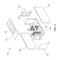
- FIG. 2 is an expanded view of the conventional ARINC 600 enclosure illustrated in FIG. 1 .
- FIG. 3 is an illustration of a sealable enclosure 300 constructed in accordance with embodiments of the present invention.
- FIG. 4 is a cross-sectional view of an interior portion of the enclosure illustrated in FIG. 3 .
- a component As used in this application, the terms “component”, “module”, “system”, “interface”, or the like are generally intended to refer to a computer-related entity, either hardware, a combination of hardware and software, software, or software in execution.
- a component may be, but is not limited to being, a process running on a processor, a processor, an object, an executable, a thread of execution, a program, and/or a computer.
- FIG. 2 is an expanded view 200 of the conventional ARINC 600 enclosure 100 illustrated in FIG. 1 .
- the LRU enclosure 100 includes a main chassis body 202 having a bottom panel portion 204 and a top panel portion 206 .
- the enclosure 100 also includes a wall portion including side panels 208 , 210 , 212 , and 214 .
- PCBs 216 affixed to the main chassis body 202 , include electronic devices (not shown) that, among other things, produce and dissipate heat.
- FIG. 3 is an illustration of a sealable enclosure 300 constructed in accordance with embodiments of the present invention.
- an exterior portion of the enclosure 300 viewable in FIG. 3 , will be in contact with an external environment (e.g., outside world).
- Electronic devices, mounted on PCBs, are hermetically encapsulated inside the enclosure 300 .
- the idea of the enclosure 300 is that the encapsulated electronics can be cooled with air in accordance with the ARINC 600 standards while the electronics are encapsulated—without the electronic devices being exposed to air from the external environment.
- the enclosure 300 can achieve an IP65, IP66, and IP67 Titans rating and can achieve valve pressures in accordance with the ARINC 600 standards. Valves are used in enclosures, such as the enclosure 300 , to facilitate decompression. Tightness of the seal can be achieved through the use of gaskets and sealed screws.
- the enclosure 300 includes a main body 301 , top and bottom panel portions 302 and 304 , respectively, along with side panel portions 306 , 308 , 310 , and 312 .
- the side panel portions 306 and 308 include fins (e.g., heat sinks) 314 and 316 , respectively.
- the side panel portion 312 is formed of an input/output (IO) PCB configured for mounting electronic devices.
- IO input/output
- the top 302 , bottom 304 , and side panel portions 306 , 308 , 310 , and 312 can be hermetically sealed.
- the I/O PCB 312 serves as a backplane and is an integral component of the sealing process.
- the electronic devices can be mounted on one side of the PCB 312 .
- a connector 318 is mounted on the other side of the PCB 312 .
- the electronic devices are encapsulated within the main body 301 .
- air can stream around the main body 301 , which can be covered by simple sheet metal external enclosure (illustrated in FIG. 4 ). As the air streams, it also blows across the heat sinks 314 and 316 , facilitating the transfer of heat from the heat sinks 314 at 316 into the cooling air via a convection process.
- the simple sheet metal will have openings at top and bottom sections according to the ARINC 600 specification standard.
- the heat sinks 314 and 316 absorb and evacuate the produced by the electronic devices.
- the cooling air can then be evacuated out of the top and bottom of the sheet metal external enclosure. In this manner, the electronic devices are never directly exposed to the cooling air.
- Electronics are encapsulated within the main body 301 of the enclosure 300 (i.e., inner enclosure).
- the heat produced by the electronic devices is absorbed by the heat sinks 314 at 316 by heat conduction.
- a more detailed explanation of the cooling of the encapsulated portion of the main body 301 is provided below.
- FIG. 4 is a cross-sectional view of an interior portion 400 of the enclosure 300 .
- cooling air represented by arrows 402 , enters at the bottom of the external enclosure 401 and streams around 403 the encapsulated main body 301 .
- the cooling air after being heated by the electronic devices, exits 404 the outer enclosure 401 at a desired outlet location in accordance with the ARINC 600 specification.
- the cooling air evacuates the heat along the side panels 306 and 308 of the main body 301 , thus removing it from electronic devices, such as a computer module 406 and a power supply 407 .
- the computer module 406 and the power supply 407 are never exposed to the cooling air.
- the heat is transported along the side walls of the main body 301 , being absorbed by the cooling air via heat convection, and transported into the outer enclosure 401 .
- Embodiments of the present invention offer a more reliable cooling enclosure having a lower MTBF using conduction cooling, which is a more efficient cooling process.
- the air streams through the heat sinks.
- one heat sink for example, closest to the cooling air, can have a larger pressure drop.
- the ARINC 600 specification also defines a pressure drop across the LRU which must remain within specified limits. This requirement tours that the cooling air is equally distributed across the LRUs, which are generally installed parallel to each other. By way of example, once the pressure drops across the enclosure 301 , it can be adjusted to equalize any changes related to heat produced by the internal electronic devices. As noted above, valves can be used as a mechanism for controlling and facilitating the different pressure drops, pressure levels, and decompression.
- valves in essence, equalize the different pressure environments.
- the ability to accommodate different pressure levels enables the LRU's to be used at sufficiently high altitudes without the risk of destruction due, for example, to explosions because of over pressure.
- the backplane PCB 312 is used to form one of the side panels of the enclosure 301 .
- the connector 318 is attached to the PCB 312 and provides connectivity for power, as well as accommodating the input and output of processor signals. In the case of aircraft, for example, the electronics to the aircraft are transferred through the connector 318 .
- the backplane PCB 312 can be removable, a variety of gaskets can be used to facilitate a tight seal.
- an efficient type gasket is to have an O-ring configured for placement in a groove. The O-ring and the groove can be pressed into place.
- the use of an O-ring is merely one approach to attaching the backplane PCB 312 and forming a tight seal.
- the O-ring, or other suitable sealing technique can ensure that the seal between the PCB 312 and the rest of the enclosure 300 will be devoid of any holes. Screws, with sealing material, can be used as an added measure.
- the PCB 312 can be used to actually form the seal.
- a separate plate is used as a side panel to form the seal.
Landscapes
- Engineering & Computer Science (AREA)
- Microelectronics & Electronic Packaging (AREA)
- Physics & Mathematics (AREA)
- Thermal Sciences (AREA)
- Aviation & Aerospace Engineering (AREA)
- Cooling Or The Like Of Electrical Apparatus (AREA)
Abstract
Provided is an enclosure for encapsulating one or more printed circuit boards (PCBs) configured for having electronic devices mounted thereon. The enclosure includes a main chassis body including a bottom portion and an outer wall including connectable panels for encasing the main chassis body. The enclosure also includes a top portion configured for completing a seal between the main chassis body and the outer wall, wherein one of the PCBs forms one of the connectable panels.
Description
The present invention is related to cooling hermetical encapsulated electronics. More specifically, the present invention is related to efficiently cooling electronic devices hermetically encapsulated within a sealed enclosure.
As the footprint of electronic components continues to decrease, enabling greater numbers of components to be placed on a printed circuit board (PCB), efficiently dissipating heat produced by the components becomes more challenging. This problem is amplified as even more of these PCBs are housed within a single enclosure, or chassis.
Traditionally, air is used as the catalyst for dissipating heat and cooling the electronic components electronics within the enclosure. But as the performance demands of these electronic components continues to increase, the traditional heat dissipating approaches become more inefficient and less effective. This ineffectiveness is particularly true in instances where the chassis is sealed, which is most often the case where the chassis is used as a line replaceable units (LRU).
LRUs are used primarily as modular components on aircraft and typically contain aircraft electronics. Usually, these enclosures are not sealed. Cooling air streams through the enclosure in order to remove heat generated by the electronics inside the enclosure. These LRU's are widely used, for example, in military aircraft applications. The Aeronautical Radio, Incorporated (ARINC) 600 standards specification defines rack and panel sizes, weights, connectors, mounting positions, cooling features, and other characteristics associated with aircraft LRU's. Also, available air mass, according to the size of the LRU, is specified. The air mass is used to cool the electronic devices inside the LRU. FIG. 1 , for example, is an illustration of an ARINC 600 LRU enclosure 100, in which embodiments of the present invention may be practiced.
In FIG. 1 , the ARINC 600 enclosure includes a front panel 102 and a rear panel 104. As noted above, air masses can be used to cool electronic devices mounted on a printed circuit board (PCB) inside the enclosure 100. The ARINC 600 standards specification also governs drilled holes in a defined area at the bottom of the enclosure 100 (not shown) and drilled holes 106 at a top of the enclosure 100.
During operation, for example, cooling air can be injected into a bottom air inlet area and will stream through the enclosure 100, through the drilled holes 106, and out of the enclosure 100. This process of streaming air through the enclosure 100 removes heat from the electronic devices. This streaming air, however, exposes the electronic devices to an outer, potentially harmful, external environment. This external environment can be detrimental to the operation and reliability of the electronic devices.
For example, filtering of the external air could be deficient such that as the streaming air comes into contact with the electronic devices, the devices can be damaged. Salt filled air, for example, can have a corrosive effect on the electronics. There are many other disadvantages to the cooling mechanics of the conventional ARINC 600 LRU enclosure 100.
An additional disadvantage is that the streaming air must be filtered to a certain level in order to prevent a sandblasting effect on the electronic devices. Also, in the case of eruption of fire inside the LRU enclosure 100, smoke will be distributed along the cooling paths, permitting the fire to expand to other areas within the enclosure 100. These disadvantages can significantly impact performance, reduce the mean time between failure (MTBF) of the electronic devices, and decrease their reliability.
Given the aforementioned deficiencies, a need exists for improved techniques for cooling electronic devices mounted on PCBs within sealed LRU enclosure. More specifically, a need exists for improved cooling techniques for an ARINC 600 enclosure having encapsulated electronic devices.
An embodiment of the present invention includes an enclosure for encapsulating one or more PCBs configured for having electronic devices mounted thereon. The enclosure includes a main chassis body including a bottom portion and an outer wall including connectable panels for encasing the main chassis body. The enclosure also includes a top portion configured for completing a seal between the main chassis body and the outer wall, wherein one of the PCBs forms one of the connectable panels.
Embodiments of the present invention provide an LRU enclosure constructed in accordance with ARINC 600 specification standards. The enclosure includes inlet air streams throughout the enclosure to a top portion, and out of the enclosure. Heat dissipated from the electronic devices mounted on PCBs within the LRU will be removed via the inlet air streams. At least one of the panels of the enclosure is formed from one of the PCBs. Electronic devices mounted on this one PCB are encapsulated within the LRU enclosure.
Further features and advantages of the invention, as well as the structure and operation of various embodiments of the invention, are described in detail below with reference to the accompanying drawings. It is noted that the invention is not limited to the specific embodiments described herein. Such embodiments are presented herein for illustrative purposes only. Additional embodiments will be apparent to persons skilled in the relevant art(s) based on the teachings contained herein.
The accompanying drawings, which are incorporated herein and form part of the specification, illustrate the present invention and, together with the description, further serve to explain the principles of the invention and to enable a person skilled in the relevant art(s) to make and use the invention.
While the present invention is described herein with illustrative embodiments for particular applications, it should be understood that the invention is not limited thereto. Those skilled in the art with access to the teachings provided herein will recognize additional modifications, applications, and embodiments within the scope thereof and additional fields in which the invention would be of significant utility.
As used in this application, the terms “component”, “module”, “system”, “interface”, or the like are generally intended to refer to a computer-related entity, either hardware, a combination of hardware and software, software, or software in execution. For example, a component may be, but is not limited to being, a process running on a processor, a processor, an object, an executable, a thread of execution, a program, and/or a computer.
During operation, heat is removed when cool air is injected via inlets in the bottom portion 204 through the enclosure 100 and out of the LRU via the holes 106 in the top portion 206. As noted above, several features of the LRU enclosure 100 render its cooling capabilities as being deficient in many instances. One of the most significant disadvantages is that electronic devices mounted on the PCBs 216 are directly exposed to air from an external environment, which streams and circulates around the electronic devices.
The idea of the enclosure 300 is that the encapsulated electronics can be cooled with air in accordance with the ARINC 600 standards while the electronics are encapsulated—without the electronic devices being exposed to air from the external environment.
By way of example, the enclosure 300 can achieve an IP65, IP66, and IP67 Titans rating and can achieve valve pressures in accordance with the ARINC 600 standards. Valves are used in enclosures, such as the enclosure 300, to facilitate decompression. Tightness of the seal can be achieved through the use of gaskets and sealed screws.
The enclosure 300 includes a main body 301, top and bottom panel portions 302 and 304, respectively, along with side panel portions 306, 308, 310, and 312. The side panel portions 306 and 308 include fins (e.g., heat sinks) 314 and 316, respectively. The side panel portion 312 is formed of an input/output (IO) PCB configured for mounting electronic devices.
By way of example, and not limitation, the top 302, bottom 304, and side panel portions 306, 308, 310, and 312 can be hermetically sealed. In this example, the I/O PCB 312 serves as a backplane and is an integral component of the sealing process. The electronic devices can be mounted on one side of the PCB 312. In the exemplary enclosure 300 of FIG. 3 , a connector 318 is mounted on the other side of the PCB 312.
In the enclosure 300, the electronic devices are encapsulated within the main body 301. To facilitate cooling, air can stream around the main body 301, which can be covered by simple sheet metal external enclosure (illustrated in FIG. 4 ). As the air streams, it also blows across the heat sinks 314 and 316, facilitating the transfer of heat from the heat sinks 314 at 316 into the cooling air via a convection process.
The simple sheet metal will have openings at top and bottom sections according to the ARINC 600 specification standard. As cooling air streams in through the bottom and streams along the side on the heat sinks 314 and 316 of the main body 301, the heat sinks 314 and 316 absorb and evacuate the produced by the electronic devices. The cooling air can then be evacuated out of the top and bottom of the sheet metal external enclosure. In this manner, the electronic devices are never directly exposed to the cooling air.
Electronics are encapsulated within the main body 301 of the enclosure 300 (i.e., inner enclosure). The heat produced by the electronic devices is absorbed by the heat sinks 314 at 316 by heat conduction. A more detailed explanation of the cooling of the encapsulated portion of the main body 301 is provided below.
In the manner above, the cooling air evacuates the heat along the side panels 306 and 308 of the main body 301, thus removing it from electronic devices, such as a computer module 406 and a power supply 407. The computer module 406 and the power supply 407 are never exposed to the cooling air. The heat is transported along the side walls of the main body 301, being absorbed by the cooling air via heat convection, and transported into the outer enclosure 401.
Embodiments of the present invention offer a more reliable cooling enclosure having a lower MTBF using conduction cooling, which is a more efficient cooling process. With respect to the ARINC 600 specification, with different PCBs having different heat sinks, the air streams through the heat sinks. In this scenario, one heat sink, for example, closest to the cooling air, can have a larger pressure drop.
The ARINC 600 specification also defines a pressure drop across the LRU which must remain within specified limits. This requirement tours that the cooling air is equally distributed across the LRUs, which are generally installed parallel to each other. By way of example, once the pressure drops across the enclosure 301, it can be adjusted to equalize any changes related to heat produced by the internal electronic devices. As noted above, valves can be used as a mechanism for controlling and facilitating the different pressure drops, pressure levels, and decompression.
The valves, in essence, equalize the different pressure environments. The ability to accommodate different pressure levels enables the LRU's to be used at sufficiently high altitudes without the risk of destruction due, for example, to explosions because of over pressure.
Referring back to FIG. 3 , the backplane PCB 312 is used to form one of the side panels of the enclosure 301. The connector 318 is attached to the PCB 312 and provides connectivity for power, as well as accommodating the input and output of processor signals. In the case of aircraft, for example, the electronics to the aircraft are transferred through the connector 318.
Since the backplane PCB 312 can be removable, a variety of gaskets can be used to facilitate a tight seal. On example of an efficient type gasket is to have an O-ring configured for placement in a groove. The O-ring and the groove can be pressed into place. The use of an O-ring is merely one approach to attaching the backplane PCB 312 and forming a tight seal. The O-ring, or other suitable sealing technique, can ensure that the seal between the PCB 312 and the rest of the enclosure 300 will be devoid of any holes. Screws, with sealing material, can be used as an added measure. Using this approach, the PCB 312 can be used to actually form the seal. In conventional ARINC 600 LRUs, for example, a separate plate is used as a side panel to form the seal.
It is to be appreciated that the Detailed Description section, and not the Summary and Abstract sections, is intended to be used to interpret the claims. The Summary and Abstract sections may set forth one or more but not all exemplary embodiments of the present invention as contemplated by the inventor(s), and thus, are not intended to limit the present invention and the appended claims in any way.
Claims (20)
1. An enclosure for encapsulating one or more printed circuit boards (PCBs) inside the enclosure, the one or more PCBs configured for having electronic devices mounted thereon, comprising:
a main chassis body including a bottom portion;
an outer wall including connectable panels for encasing the main chassis body;
and
a top portion configured for completing a seal between the main chassis body and the outer wall;
wherein a PCB forms one of the connectable panels.
2. The enclosure of claim 1 , wherein the one PCB forms a seal between the main chassis body, the outer wall, and the top portion.
3. The enclosure of claim 2 , wherein electronic devices mounted on the PCB that forms one of the connectable panels are positioned within the enclosure.
4. The enclosure of claim 1 , wherein the encapsulating is in accordance with Aeronautical Radio, Incorporated (ARINC) 600 standards.
5. The enclosure of claim 4 , wherein one or more of the connectable panels includes a heat evacuation mechanism.
6. The enclosure of claim 5 , wherein the heat evacuation mechanism includes a heat sink.
7. The enclosure of claim 6 , wherein the seal is a hermetic seal.
8. The enclosure of claim 7 , further comprising an external enclosure for housing the main body.
9. The enclosure of claim 1 , wherein the electronic devices mounted on the one or more PCBs inside the enclosure are not exposed to an environment outside of the enclosure.
10. The enclosure of claim 1 , wherein the enclosure further comprises a valve configured to facilitate decompression of the inside of the enclosure.
11. An enclosure for encapsulating one or more printed circuit boards (PCBs) inside the enclosure, the one or more PCBs configured for having electronic devices mounted thereon, comprising:
a main chassis body including a bottom portion;
an outer wall including connectable panels for encasing the main chassis body; and
a top portion configured for completing a seal between the main chassis body and the outer wall;
wherein a PCB forms one of the connectable panels;
wherein one or more of the connectable panels includes a heat conduction mechanism for absorbing heat from the electronic devices.
12. The enclosure of claim 11 , wherein the enclosure is configured to facilitate circulation of cooling air external to the main chassis body, the heat being absorbed by the cooling via convection.
13. The enclosure of claim 11 , wherein the PCB that forms one of the connectable panels forms the seal between the main chassis body, the outer wall, and the top portion.
14. The enclosure of claim 12 , wherein the encapsulating is in accordance with Aeronautical Radio, Incorporated (ARINC) 600 standards.
15. The enclosure of claim 13 , wherein electronic devices mounted on the PCB that forms one of the connectable panels are positioned within the enclosure.
16. The enclosure of claim 15 , wherein the heat conduction mechanism includes a heat sink.
17. The enclosure of claim 16 , wherein the seal is a hermetic seal.
18. An enclosure constructed in accordance with Aeronautical Radio, Incorporated (ARINC) 600 standards for encapsulating one or more printed circuit boards (PCBs) inside the enclosure, the one or more PCBs configured for having electronic devices mounted thereon, comprising:
a main chassis body including a bottom portion;
an outer wall including connectable panels for encasing the main chassis body; and
a top portion configured for completing a seal between the main chassis body and the outer wall;
wherein a PCB forms one of the connectable panels;
wherein one or more of the connectable panels includes a heat conduction mechanism for absorbing heat from the electronic devices.
19. The enclosure of claim 18 , wherein the heat conduction mechanism includes a heat sink.
20. The enclosure of claim 19 , wherein the seal is a hermetic seal.
Applications Claiming Priority (1)
| Application Number | Priority Date | Filing Date | Title |
|---|---|---|---|
| PCT/US2013/061329 WO2015047217A1 (en) | 2013-09-24 | 2013-09-24 | An improved enclosure for hermetical encapsulated electronics |
Publications (1)
| Publication Number | Publication Date |
|---|---|
| US9801303B2 true US9801303B2 (en) | 2017-10-24 |
Family
ID=49293925
Family Applications (2)
| Application Number | Title | Priority Date | Filing Date |
|---|---|---|---|
| US15/024,715 Granted US20160234964A1 (en) | 2013-09-24 | 2012-09-24 | An improved enclosure for hermetical encapsulated electronics |
| US15/024,715 Active US9801303B2 (en) | 2013-09-24 | 2013-09-24 | Enclosure for hermetical encapsulated electronics |
Family Applications Before (1)
| Application Number | Title | Priority Date | Filing Date |
|---|---|---|---|
| US15/024,715 Granted US20160234964A1 (en) | 2013-09-24 | 2012-09-24 | An improved enclosure for hermetical encapsulated electronics |
Country Status (2)
| Country | Link |
|---|---|
| US (2) | US20160234964A1 (en) |
| WO (1) | WO2015047217A1 (en) |
Families Citing this family (2)
| Publication number | Priority date | Publication date | Assignee | Title |
|---|---|---|---|---|
| GB2565131B (en) | 2017-08-04 | 2021-07-28 | Ge Aviat Systems Ltd | Modular power system and method of mitigating failure propagation between a plurality of modules in a modular power system |
| US10945347B2 (en) * | 2018-12-27 | 2021-03-09 | lonQ, Inc. | Techniques for making hermetic feedthroughs for enclosures |
Citations (23)
| Publication number | Priority date | Publication date | Assignee | Title |
|---|---|---|---|---|
| GB1326972A (en) | 1972-03-16 | 1973-08-15 | Elliott Brothers London Ltd | Electrical circuit assemblies |
| US4458296A (en) | 1982-05-19 | 1984-07-03 | The Boeing Company | Avionic shelf assembly |
| GB2230147A (en) | 1988-12-23 | 1990-10-10 | Plessey Co Plc | Housing for electronic modules |
| US5170320A (en) | 1991-08-29 | 1992-12-08 | Hollingsead International, Inc. | Avionic tray and detachable metering plate |
| US5190241A (en) | 1991-10-18 | 1993-03-02 | Hollingsead International, Inc. | Avionic tray and method of making same |
| US5570270A (en) | 1994-06-03 | 1996-10-29 | Pulse Electronics, Inc. | Chassis and personal computer for severe environment embedded applications |
| EP0824302A1 (en) | 1996-08-13 | 1998-02-18 | Bodenseewerk Gerätetechnik GmbH | Modular electronic apparatus |
| US5737194A (en) | 1996-07-29 | 1998-04-07 | Cray Research, Inc. | Input/output module assembly |
| US5940266A (en) | 1997-10-14 | 1999-08-17 | International Business Machines Corporation | Bi-directional cooling arrangement for use with an electronic component enclosure |
| US5995368A (en) | 1998-10-20 | 1999-11-30 | Nortel Networks Corporation | Air flow distribution device for shelf-based circuit cards |
| US20020012236A1 (en) | 1998-12-31 | 2002-01-31 | Dimarco Mario | Methods and apparatus for circuit integration |
| US6797879B2 (en) | 2002-09-17 | 2004-09-28 | The Boeing Company | Avionics tray assembly and seal assembly |
| US20070211711A1 (en) * | 2006-03-08 | 2007-09-13 | Clayton James E | Thin multichip flex-module |
| US20080273316A1 (en) | 2005-12-07 | 2008-11-06 | Thales | Lightweight Rigid Case for Electronic Apparatus |
| US20090213543A1 (en) | 2005-05-24 | 2009-08-27 | Thales | Modular electronic device operating in difficult environments |
| US20090244831A1 (en) | 2008-04-01 | 2009-10-01 | Thales | Computer with simplified layout, designed for aviation |
| FR2933267A1 (en) | 2008-06-27 | 2010-01-01 | Thales Sa | Electronic cabinet for receiving electronic components of airplane, has enclosure incorporating electronic board that is surrounded by aeraulics circuit, with wall incorporating motherboard, to circulate refrigerant to interior of cabinet |
| US20100008053A1 (en) | 2005-09-19 | 2010-01-14 | Airbus Deutschland Gmbh | Avionics equipment carrier system with quick-mount housing and quick-mount modules |
| US20100033920A1 (en) | 2008-08-05 | 2010-02-11 | Thales | Aeraulic Cooling Device for a "Full ARINC" Computer |
| US7869209B2 (en) | 2006-08-30 | 2011-01-11 | Thales | Electronic rack combining natural convection and forced air circulation for its cooling |
| US20120069519A1 (en) * | 2010-08-19 | 2012-03-22 | Airbus Operations (S.A.S.) | Fluid-cooled electrical equipment, avionic rack to receive such equipment and aircraft equipped with such racks |
| US20120285665A1 (en) | 2011-05-13 | 2012-11-15 | Airbus Operations (S.A.S.) | Method for distribution of cooling air for electrical equipment installed in an avionic bay and aircraft equipped with such a bay |
| US20130170132A1 (en) | 2012-01-04 | 2013-07-04 | Thales | Electronic Computer Comprising an Air Channeling System for Cooling Electronic Boards |
-
2012
- 2012-09-24 US US15/024,715 patent/US20160234964A1/en active Granted
-
2013
- 2013-09-24 US US15/024,715 patent/US9801303B2/en active Active
- 2013-09-24 WO PCT/US2013/061329 patent/WO2015047217A1/en active Application Filing
Patent Citations (24)
| Publication number | Priority date | Publication date | Assignee | Title |
|---|---|---|---|---|
| GB1326972A (en) | 1972-03-16 | 1973-08-15 | Elliott Brothers London Ltd | Electrical circuit assemblies |
| US4458296A (en) | 1982-05-19 | 1984-07-03 | The Boeing Company | Avionic shelf assembly |
| GB2230147A (en) | 1988-12-23 | 1990-10-10 | Plessey Co Plc | Housing for electronic modules |
| US5170320A (en) | 1991-08-29 | 1992-12-08 | Hollingsead International, Inc. | Avionic tray and detachable metering plate |
| US5190241A (en) | 1991-10-18 | 1993-03-02 | Hollingsead International, Inc. | Avionic tray and method of making same |
| US5570270A (en) | 1994-06-03 | 1996-10-29 | Pulse Electronics, Inc. | Chassis and personal computer for severe environment embedded applications |
| US5737194A (en) | 1996-07-29 | 1998-04-07 | Cray Research, Inc. | Input/output module assembly |
| EP0824302A1 (en) | 1996-08-13 | 1998-02-18 | Bodenseewerk Gerätetechnik GmbH | Modular electronic apparatus |
| EP0824302B1 (en) * | 1996-08-13 | 2001-05-16 | Bodenseewerk Gerätetechnik GmbH | Modular electronic apparatus |
| US5940266A (en) | 1997-10-14 | 1999-08-17 | International Business Machines Corporation | Bi-directional cooling arrangement for use with an electronic component enclosure |
| US5995368A (en) | 1998-10-20 | 1999-11-30 | Nortel Networks Corporation | Air flow distribution device for shelf-based circuit cards |
| US20020012236A1 (en) | 1998-12-31 | 2002-01-31 | Dimarco Mario | Methods and apparatus for circuit integration |
| US6797879B2 (en) | 2002-09-17 | 2004-09-28 | The Boeing Company | Avionics tray assembly and seal assembly |
| US20090213543A1 (en) | 2005-05-24 | 2009-08-27 | Thales | Modular electronic device operating in difficult environments |
| US20100008053A1 (en) | 2005-09-19 | 2010-01-14 | Airbus Deutschland Gmbh | Avionics equipment carrier system with quick-mount housing and quick-mount modules |
| US20080273316A1 (en) | 2005-12-07 | 2008-11-06 | Thales | Lightweight Rigid Case for Electronic Apparatus |
| US20070211711A1 (en) * | 2006-03-08 | 2007-09-13 | Clayton James E | Thin multichip flex-module |
| US7869209B2 (en) | 2006-08-30 | 2011-01-11 | Thales | Electronic rack combining natural convection and forced air circulation for its cooling |
| US20090244831A1 (en) | 2008-04-01 | 2009-10-01 | Thales | Computer with simplified layout, designed for aviation |
| FR2933267A1 (en) | 2008-06-27 | 2010-01-01 | Thales Sa | Electronic cabinet for receiving electronic components of airplane, has enclosure incorporating electronic board that is surrounded by aeraulics circuit, with wall incorporating motherboard, to circulate refrigerant to interior of cabinet |
| US20100033920A1 (en) | 2008-08-05 | 2010-02-11 | Thales | Aeraulic Cooling Device for a "Full ARINC" Computer |
| US20120069519A1 (en) * | 2010-08-19 | 2012-03-22 | Airbus Operations (S.A.S.) | Fluid-cooled electrical equipment, avionic rack to receive such equipment and aircraft equipped with such racks |
| US20120285665A1 (en) | 2011-05-13 | 2012-11-15 | Airbus Operations (S.A.S.) | Method for distribution of cooling air for electrical equipment installed in an avionic bay and aircraft equipped with such a bay |
| US20130170132A1 (en) | 2012-01-04 | 2013-07-04 | Thales | Electronic Computer Comprising an Air Channeling System for Cooling Electronic Boards |
Non-Patent Citations (1)
| Title |
|---|
| PCT Search Report and Written Opinion issued in connection with corresponding PCT Application No. PCT/US2013/061329 dated May 28, 2014. |
Also Published As
| Publication number | Publication date |
|---|---|
| WO2015047217A1 (en) | 2015-04-02 |
| US20160234964A1 (en) | 2016-08-11 |
Similar Documents
| Publication | Publication Date | Title |
|---|---|---|
| US8031464B2 (en) | Ruggedized computer capable of operating in high-temperature environments | |
| US9974157B2 (en) | Circuit card cartridge for an electronic system | |
| US10687446B2 (en) | Back to back electronic display assembly | |
| US5740018A (en) | Environmentally controlled circuit pack and cabinet | |
| RU2398368C2 (en) | Modular electronic device for operation under severe conditions | |
| US7863528B2 (en) | Housing with thermal bridge | |
| US8014146B2 (en) | Computer system with airflow blocking plate | |
| JP2006173609A (en) | Electronic system for reducing electromagnetic interference and method for configuring it | |
| US20160169594A1 (en) | Heatspreader with extended surface for heat transfer through a sealed chassis wall | |
| US20170359926A1 (en) | Electromagnetic interference shielding configuration of electronic device | |
| US9801303B2 (en) | Enclosure for hermetical encapsulated electronics | |
| US11314154B2 (en) | Ducted cooling system of a camera | |
| EP3195082A1 (en) | Reduction of intake resistance for air flow enhancement | |
| TW201304667A (en) | Heat dissipating system for electronic device | |
| CN112469236A (en) | Cell body and switching module thereof | |
| KR102006798B1 (en) | Outdoor Enclosure for Electric System | |
| US10165708B2 (en) | Cooling mechanism used inside gimbal | |
| JPH1089820A (en) | Sealing case for containing heating element | |
| RU94732U1 (en) | EXTERNAL COOLING OF AN INDUSTRIAL COMPUTER | |
| KR100846771B1 (en) | Plasma display unit | |
| US20240114653A1 (en) | Universal ruggedized computer system enclosure | |
| JP2007017509A (en) | Mounting structure for display device | |
| RU170544U1 (en) | MODULAR ELECTRONIC DEVICE | |
| TWM463384U (en) | All-in-one computer | |
| US11937407B2 (en) | Photo-etched chassis cooling walls |
Legal Events
| Date | Code | Title | Description |
|---|---|---|---|
| STCF | Information on status: patent grant |
Free format text: PATENTED CASE |
|
| MAFP | Maintenance fee payment |
Free format text: PAYMENT OF MAINTENANCE FEE, 4TH YEAR, LARGE ENTITY (ORIGINAL EVENT CODE: M1551); ENTITY STATUS OF PATENT OWNER: LARGE ENTITY Year of fee payment: 4 |