US9799950B2 - Communication tower panel security device employing flexible plastic banding and a connecting/tensioning assembly having pass-through channels for safely securing radiation-transparent panels covering antenna service bays of a wireless telecommunication tower - Google Patents
Communication tower panel security device employing flexible plastic banding and a connecting/tensioning assembly having pass-through channels for safely securing radiation-transparent panels covering antenna service bays of a wireless telecommunication tower Download PDFInfo
- Publication number
- US9799950B2 US9799950B2 US15/221,712 US201615221712A US9799950B2 US 9799950 B2 US9799950 B2 US 9799950B2 US 201615221712 A US201615221712 A US 201615221712A US 9799950 B2 US9799950 B2 US 9799950B2
- Authority
- US
- United States
- Prior art keywords
- communication tower
- flexible plastic
- length
- security device
- channel
- Prior art date
- Legal status (The legal status is an assumption and is not a legal conclusion. Google has not performed a legal analysis and makes no representation as to the accuracy of the status listed.)
- Expired - Fee Related
Links
- 238000004891 communication Methods 0.000 title claims abstract description 563
- 229920002457 flexible plastic Polymers 0.000 title claims abstract description 207
- 239000000463 material Substances 0.000 claims description 83
- 230000007246 mechanism Effects 0.000 claims description 78
- 238000007906 compression Methods 0.000 claims description 30
- 230000006835 compression Effects 0.000 claims description 30
- 230000002441 reversible effect Effects 0.000 claims description 20
- 230000001154 acute effect Effects 0.000 claims description 10
- 239000003292 glue Substances 0.000 claims description 5
- 239000003000 extruded plastic Substances 0.000 claims 2
- 239000002991 molded plastic Substances 0.000 claims 2
- 230000010267 cellular communication Effects 0.000 abstract description 27
- 230000002411 adverse Effects 0.000 abstract description 2
- 229920003023 plastic Polymers 0.000 description 159
- 239000004033 plastic Substances 0.000 description 159
- 238000009434 installation Methods 0.000 description 41
- 238000000034 method Methods 0.000 description 28
- 230000000717 retained effect Effects 0.000 description 20
- 230000008901 benefit Effects 0.000 description 11
- 238000006073 displacement reaction Methods 0.000 description 10
- 229910052751 metal Inorganic materials 0.000 description 10
- 239000002184 metal Substances 0.000 description 10
- 230000037361 pathway Effects 0.000 description 10
- 230000008878 coupling Effects 0.000 description 8
- 238000010168 coupling process Methods 0.000 description 8
- 238000005859 coupling reaction Methods 0.000 description 8
- 238000004804 winding Methods 0.000 description 8
- 238000005299 abrasion Methods 0.000 description 6
- 230000001413 cellular effect Effects 0.000 description 6
- 230000008569 process Effects 0.000 description 6
- 238000010276 construction Methods 0.000 description 4
- 238000013461 design Methods 0.000 description 4
- 230000001681 protective effect Effects 0.000 description 4
- -1 Delrin) Chemical class 0.000 description 3
- 230000000712 assembly Effects 0.000 description 3
- 238000000429 assembly Methods 0.000 description 3
- 238000005516 engineering process Methods 0.000 description 3
- 238000004519 manufacturing process Methods 0.000 description 3
- 230000002028 premature Effects 0.000 description 3
- 230000005855 radiation Effects 0.000 description 3
- 238000001228 spectrum Methods 0.000 description 3
- 230000023402 cell communication Effects 0.000 description 2
- 230000005670 electromagnetic radiation Effects 0.000 description 2
- 238000012423 maintenance Methods 0.000 description 2
- 150000002739 metals Chemical class 0.000 description 2
- 230000000737 periodic effect Effects 0.000 description 2
- 239000004417 polycarbonate Substances 0.000 description 2
- 229920000515 polycarbonate Polymers 0.000 description 2
- 229920002635 polyurethane Polymers 0.000 description 2
- 239000004814 polyurethane Substances 0.000 description 2
- 238000010079 rubber tapping Methods 0.000 description 2
- 238000010146 3D printing Methods 0.000 description 1
- IRLPACMLTUPBCL-KQYNXXCUSA-N 5'-adenylyl sulfate Chemical compound C1=NC=2C(N)=NC=NC=2N1[C@@H]1O[C@H](COP(O)(=O)OS(O)(=O)=O)[C@@H](O)[C@H]1O IRLPACMLTUPBCL-KQYNXXCUSA-N 0.000 description 1
- 229920001651 Cyanoacrylate Polymers 0.000 description 1
- 229920004943 Delrin® Polymers 0.000 description 1
- LFQSCWFLJHTTHZ-UHFFFAOYSA-N Ethanol Chemical compound CCO LFQSCWFLJHTTHZ-UHFFFAOYSA-N 0.000 description 1
- 229920004142 LEXAN™ Polymers 0.000 description 1
- 239000004418 Lexan Substances 0.000 description 1
- 239000004677 Nylon Substances 0.000 description 1
- 239000004698 Polyethylene Substances 0.000 description 1
- 229910000831 Steel Inorganic materials 0.000 description 1
- 239000004830 Super Glue Substances 0.000 description 1
- DHKHKXVYLBGOIT-UHFFFAOYSA-N acetaldehyde Diethyl Acetal Natural products CCOC(C)OCC DHKHKXVYLBGOIT-UHFFFAOYSA-N 0.000 description 1
- 125000002777 acetyl group Chemical class [H]C([H])([H])C(*)=O 0.000 description 1
- 230000009471 action Effects 0.000 description 1
- 229910052782 aluminium Inorganic materials 0.000 description 1
- XAGFODPZIPBFFR-UHFFFAOYSA-N aluminium Chemical compound [Al] XAGFODPZIPBFFR-UHFFFAOYSA-N 0.000 description 1
- 238000003491 array Methods 0.000 description 1
- 238000005266 casting Methods 0.000 description 1
- 238000005260 corrosion Methods 0.000 description 1
- 230000007797 corrosion Effects 0.000 description 1
- 238000005520 cutting process Methods 0.000 description 1
- 230000006866 deterioration Effects 0.000 description 1
- 239000013013 elastic material Substances 0.000 description 1
- 239000004744 fabric Substances 0.000 description 1
- 229920001903 high density polyethylene Polymers 0.000 description 1
- 239000004700 high-density polyethylene Substances 0.000 description 1
- 238000002347 injection Methods 0.000 description 1
- 239000007924 injection Substances 0.000 description 1
- 238000001746 injection moulding Methods 0.000 description 1
- 238000003780 insertion Methods 0.000 description 1
- 230000037431 insertion Effects 0.000 description 1
- 238000011900 installation process Methods 0.000 description 1
- 230000007774 longterm Effects 0.000 description 1
- 239000003550 marker Substances 0.000 description 1
- 238000010295 mobile communication Methods 0.000 description 1
- 238000012986 modification Methods 0.000 description 1
- 230000004048 modification Effects 0.000 description 1
- 229910052755 nonmetal Inorganic materials 0.000 description 1
- 150000002843 nonmetals Chemical class 0.000 description 1
- 229920001778 nylon Polymers 0.000 description 1
- 230000036961 partial effect Effects 0.000 description 1
- 229920000573 polyethylene Polymers 0.000 description 1
- 238000002360 preparation method Methods 0.000 description 1
- 230000001737 promoting effect Effects 0.000 description 1
- 238000007789 sealing Methods 0.000 description 1
- 238000004513 sizing Methods 0.000 description 1
- 229910001220 stainless steel Inorganic materials 0.000 description 1
- 239000010935 stainless steel Substances 0.000 description 1
- 239000010959 steel Substances 0.000 description 1
- 229920001187 thermosetting polymer Polymers 0.000 description 1
- 239000012780 transparent material Substances 0.000 description 1
- 229920000785 ultra high molecular weight polyethylene Polymers 0.000 description 1
- 238000009827 uniform distribution Methods 0.000 description 1
Images


Classifications
-
- H—ELECTRICITY
- H01—ELECTRIC ELEMENTS
- H01Q—ANTENNAS, i.e. RADIO AERIALS
- H01Q1/00—Details of, or arrangements associated with, antennas
- H01Q1/42—Housings not intimately mechanically associated with radiating elements, e.g. radome
-
- F—MECHANICAL ENGINEERING; LIGHTING; HEATING; WEAPONS; BLASTING
- F16—ENGINEERING ELEMENTS AND UNITS; GENERAL MEASURES FOR PRODUCING AND MAINTAINING EFFECTIVE FUNCTIONING OF MACHINES OR INSTALLATIONS; THERMAL INSULATION IN GENERAL
- F16B—DEVICES FOR FASTENING OR SECURING CONSTRUCTIONAL ELEMENTS OR MACHINE PARTS TOGETHER, e.g. NAILS, BOLTS, CIRCLIPS, CLAMPS, CLIPS OR WEDGES; JOINTS OR JOINTING
- F16B2/00—Friction-grip releasable fastenings
- F16B2/02—Clamps, i.e. with gripping action effected by positive means other than the inherent resistance to deformation of the material of the fastening
- F16B2/06—Clamps, i.e. with gripping action effected by positive means other than the inherent resistance to deformation of the material of the fastening external, i.e. with contracting action
- F16B2/08—Clamps, i.e. with gripping action effected by positive means other than the inherent resistance to deformation of the material of the fastening external, i.e. with contracting action using bands
-
- H—ELECTRICITY
- H01—ELECTRIC ELEMENTS
- H01Q—ANTENNAS, i.e. RADIO AERIALS
- H01Q1/00—Details of, or arrangements associated with, antennas
- H01Q1/12—Supports; Mounting means
- H01Q1/1242—Rigid masts specially adapted for supporting an aerial
-
- H—ELECTRICITY
- H01—ELECTRIC ELEMENTS
- H01Q—ANTENNAS, i.e. RADIO AERIALS
- H01Q1/00—Details of, or arrangements associated with, antennas
- H01Q1/12—Supports; Mounting means
- H01Q1/18—Means for stabilising antennas on an unstable platform
-
- H—ELECTRICITY
- H01—ELECTRIC ELEMENTS
- H01Q—ANTENNAS, i.e. RADIO AERIALS
- H01Q1/00—Details of, or arrangements associated with, antennas
- H01Q1/44—Details of, or arrangements associated with, antennas using equipment having another main function to serve additionally as an antenna, e.g. means for giving an antenna an aesthetic aspect
-
- H—ELECTRICITY
- H01—ELECTRIC ELEMENTS
- H01Q—ANTENNAS, i.e. RADIO AERIALS
- H01Q1/00—Details of, or arrangements associated with, antennas
- H01Q1/12—Supports; Mounting means
- H01Q1/22—Supports; Mounting means by structural association with other equipment or articles
- H01Q1/24—Supports; Mounting means by structural association with other equipment or articles with receiving set
- H01Q1/241—Supports; Mounting means by structural association with other equipment or articles with receiving set used in mobile communications, e.g. GSM
- H01Q1/246—Supports; Mounting means by structural association with other equipment or articles with receiving set used in mobile communications, e.g. GSM specially adapted for base stations
Definitions
- the present invention relates to improvements in methods of and apparatus for securing cover panels or shrouds to the mast structures of ground-based wireless telecommunication towers, so as to conceal and protect electromagnetic signal transmitting and receiving antennas mounted therein as part of greater diverse wireless telecommunication networks which extend across the Earth.
- each such cell tower also functions as a flag pole structure capable of flying a large flag and promoting the spirit of patriotism across the land.
- FIGS. 1A and 1B show a cell tower flag pole structure 1 employing a conventional system of spring-biased (i.e. spring-loaded) panel banding devices 2 that wrap around the circumference of the cell-tower flag pole structure 1 at different height locations, and secure the cover (i.e. shroud) panels in place against displacement in the presence of high winds and other foul weather conditions.
- spring-biased i.e. spring-loaded
- FIG. 2A shows the conventional cell tower flag pole structure of FIGS. 1A and 1B , with the flag 3 and its truck assembly 4 , as well as the cover panels 5 covering the top three sections 6 A, 6 B and 6 C, removed from the top of the flag pole structure, revealing antenna structures 7 and associated electronics.
- FIG. 3A shows the cell tower flag pole structure 1 shown in FIGS. 1A and 1B , with a set of spring-biased panel banding devices 2 wrapped around the circumference of the cell-tower flag pole structure at different height locations, to secure the panels in place against displacement in the presence of high winds and other foul weather conditions.
- FIG. 3B shows the cell tower flag pole structure 1 supporting a set of spring-biased panel banding devices 2 , each being wrapped around the circumference of the cell-tower flag pole structure at different height locations, to secure the panels 5 in place (ii) using a metal strap 2 A covered in rigid (i.e. non-compressible) protective plastic tubing 2 B to prevent fraying, ripping or abrasion of a mounted flag, and (iii) connected together using a latched and spring-loaded strap connecting assembly.
- a metal strap 2 A covered in rigid (i.e. non-compressible) protective plastic tubing 2 B to prevent fraying, ripping or abrasion of a mounted flag, and (iii) connected together using a latched and spring-loaded strap connecting assembly.
- FIGS. 4A and 4B show the topmost spring-loaded panel banding device 2 wrapped around the circumference of the cell-tower flag pole structure, in its closed/locked configuration, to secure the panels 5 in place against displacement in the presence of high winds and other foul weather conditions.
- FIG. 4C shows the topmost spring-biased panel banding device 2 wrapped around the circumference of the cell-tower flag pole structure, arranged in its unlocked configuration, with the latching mechanism 2 C, connected to the first end of the metal band 2 A by way of a spring 2 D and the second end of the metal band 2 A by way of hook 2 E. As shown, the metal band 2 A passes through an aperture formed in the hinged cover structure 2 F.
- the latching mechanism 2 C securely mounted on base panel 2 H, is arranged in its closed configuration with its spring 2 D arranged under very high-tension in its extended/stretched state, while the metal band 2 A firmly presses against the rigid protective tubing 2 B and tower panels 5 , to secure the tower panels 5 in position against the underlying tower framework (e.g. mast structure).
- the underlying tower framework e.g. mast structure
- FIGS. 5A and 5B show the first step of mounting conventional spring-biased panel banding device 2 to the cover panel of the cell-tower flag pole structure, involving the passing of four self-tapping screws 2 G through the four corner holes of the base portion 2 H of the banding device into the cover panel section 5 , to mount the panel banding device 2 to the cover panel section.
- FIG. 5C shows the second step of mounting the spring-biased panel banding device 2 to the cover panel 5 of the cell-tower flag pole structure, involving the wrapping of the covered strap 2 B around the tower 5 , and connecting the hook fastener 2 E to the free looped-end of the metal band 2 A, as shown.
- FIG. 5D shows the third step of mounting the spring-biased panel banding device 2 to the cover panel of the cell-tower flag pole structure, involving closing the latch mechanism 2 C to tighten up the covered strap 2 A extending around the panel sections 5 of the tower structure.
- FIG. 5E shows the fourth step of mounting spring-biased panel banding device 2 to the cover panel of the cell-tower flag pole structure, involving closing the cover portion 2 F over the base portion 2 H, thereby expanding the spring within the panel-banding device, tightening the covered strap against the cover panel sections 5 , and thereafter, inserting the retaining pins to secure the cover and base portions while arranged in the closed configuration.
- Applicants have observed the occurrence of shroud panel failure under extreme weather conditions when wind speeds can reach in the neighborhood of 50 MPH.
- halyards have experienced significant premature wear due to sharp external components (e.g. screw heads, edges, etc) on tower shrouds.
- halyard rope frequently suffer from entanglement.
- the above-described prior art communication tower panel security device can present potential RF interference problems due to its high use of metal content in product manufacture. It also has application to a limited range of tower diameters, and its range of tension is limited without the use of special tools. Also, the current method of installation can be difficult to practice consistently by others without the use of special tools, and there is a great need for simplification.
- a primary object of the present disclosure is to provide new and improved methods of and apparatus for safely securing cover panels on wireless communication tower structures, in diverse environments, while avoiding the shortcomings and drawbacks of prior art systems, apparatus and methodologies.
- Another object is to provide such apparatus in the form of a new and improved communication tower cover panel banding device that easily mounts to and safely secures cover panels on the communication towers, and prevents them from falling off in high winds and/or other adverse weather conditions.
- Another object of the present invention is to provide a new and improved communication tower cover panel security device that avoids premature wear and tear of halyards and flag pole cords mounted on communication tower shrouds (i.e. cover panels).
- Another object of the present invention is to provide a new and improved communication tower cover panel security device that is totally transparent to the electromagnetic energy transmitted and received by the antennas which are covered by the cover panels that the device secures, so as to completely avoid any potential electromagnetic signal interference problems when installed about the cover panels mounted about the antenna service bays of wireless communication towers.
- Another object of the present invention is to provide a new and improved communication tower cover panel security device has application over a very wide range of tower diameters, and is capable of generating a wide range of shroud banding tensions without the use of special tools.
- Another object of the present invention is to provide a new and improved communication tower cover panel security device can be safely and consistently installed in simple manner, with faster installation times than when using prior art methods, and without the use of special tools.
- Another object of the present invention is to provide a new and improved communication tower cover panel security device can be installed in the middle section of antenna service bays on communication towers.
- Another object of the present invention is to provide a new and improved communication tower cover panel security device can offers a wide tightening range to significantly improve interchangeability between antenna services along a communication tower.
- Another object of the present invention is to provide new and improved communication tower cover panel security devices that maintain significantly improved compression about the shroud panels on radio communication towers.
- Another object of the present invention is to provide new and improved communication tower cover panel security devices that can withstand deterioration when expose to UV radiation and other environment elements and conditions, thereby offering improvements in operational lifetime.
- a new and improved communication tower is constructed and installed stationary relative to the Earth, comprising a mast structure mounted relative to the Earth, at least one antenna bay arranged about the mast structure and covered by radio-transparent shroud panels, concealing the at least one antenna structure supported on or about the mast structure and adapted for transmitting and/or receiving radiated energy over a specified portion of the electromagnetic spectrum.
- the communication tower includes a plurality of communication tower panel security devices, each being substantially transparent to radiated energy over the specified portion of the electromagnetic spectrum, and installed about one antenna bay.
- Each communication tower panel security device is tightly wrapped around the circumference of the communication tower at a different height location, to secure the radio-transparent cover panels against displacement in the presence of high winds and other foul weather conditions. The degree of tension along each communication tower panel security device can be manually adjusted without the use of tools.
- the communication tower panel security device of the present invention comprises a plastic banding assembly having first and second end portions and, having a length for wrapping around the circumference of said communication tower; a connecting/tensioning mechanism for connecting the first and second end portions, and generating tension along the plastic banding assembly; wherein the plastic banding assembly and the connecting/tensioning mechanism are substantially transparent to radiated energy over said specified portion of the electromagnetic spectrum; and wherein the connecting/tensioning mechanism allows the degree of tension along the communication tower panel security device to be manually adjusted without the use of tools.
- the communication tower panel security device of the present invention comprises: a flexible plastic tubing and cord assembly, having first and second end portions, and adapted for wrapping around at least two radio-transparent cover panels for an antenna service bay arranged within a communication tower, wherein the flexible plastic tubing and cord assembly includes a length of flexible plastic tubing and a length of flexible cord; and a connecting/tensioning assembly for interconnecting the first and second ends of the flexible plastic tubing and cord assembly and wrapping around the circumference of the antenna service bay and securely retaining the radio-transparent cover panels in place under tension, during expected weather conditions; wherein the connecting/tensioning mechanism allows the degree of tension along the communication tower panel security device to be manually adjusted by tensioning the length of flexible cord, without the use of tools.
- the flexible plastic tubing and cord assembly prevents fraying, ripping or abrasion of the flag and its halyard.
- the communication tower panel security device of the present invention comprises: a first end module having a connector channel, a first set of cord input and output ports, and containing a first set of pulleys; a second end module; a sliding module containing a second set of pulleys; a pair of flexible side panels; wherein the pair of flexible side panels are supported in a parallel relationship between the first end module and the second end module to form a connecting/tensioning framework, along which the sliding module is slidably mounted so as to freely slide between the first end module and the second end module; an end connector having a head portion which is adapted to slide into and be received by the connector channel formed in said first end module; a length of flexible cord encased in a length of flexible plastic tubing and having a first end that is connected to the end connector, and wrapping about the circumference of said communication tower, and passing through the sliding module and being routed through the first end module, about the first set of pulleys, and the sliding module
- a first excess cord wind-up fixture is provided on the sliding module and a second excess cord windup fixture is provided on the second end module. Also, a second cord retaining mechanism is provided on the second end module for retaining the free end of the flexible cord after excess cord has been wound up around the first and second excess cord windup fixtures.
- the communication tower panel security device of the present invention comprises: a length of flexible plastic tubing having a first end and a second end; a length of flexible cord passing through the flexible plastic tubing and having a first end and a second end; an end connector module having a head portion and a first connector portion for connecting to the first end of the length of flexible cord, and also the first end of the length of flexible plastic tubing, wherein the length of flexible cord and tubing are capable of surrounding the circumference of the antenna service bay of said communication tower; a pair of flexible side panels, wherein each flexible side panel has a first end and a second end; a first end module having (i) an exterior connection channel for releasably receiving the head portion of the end connector module, (ii) a first pair of side panel supports for supporting the first ends of the flexible side panels, (iii) a first cord input port in communication with a first cord output port, (iv) at least a first pulley, and (v)
- the at least a first pulley comprises a first set of pulleys including a first pulley and second pulley
- the at least a second pulley comprises a second set of pulleys including a third pulley and a fourth pulley
- the first end module further comprises a second input cord port and a second cord output port
- the sliding module further comprises a second input cord port and second cord output port.
- the panel support in said second end module, closest to said communication tower allows the free end of the inner flexible side panel to freely slide in said panel support when said communication tower security device is being installed thereabout so that the pair of side panels can flex and adapt to the curvature of the communication tower.
- the first end module has an exterior side wall surface provided with a slight degree of curvature so that the side wall surface can closely adapt and fit against the curved surfaces of the tower cover panels, against which the communication tower security device is mounted.
- the second end module comprises: a frame portion supporting the central passageway and allowing the passage of the plastic tubing and cord assembly to freely pass therethrough during normal operations; an upper surface for supporting the first excess cord windup fixture; and a narrow planar exterior mounting surface facing said tower cover panel, for mounting there against during installation; wherein the second pair of side panel supports comprise a second pair of side panel support channels for supporting the second ends of the flexible side panels, respectively, with the innermost end of the side panel to freely slide within its support channel so that the side panels can bend together, and adapt to the surface curvature of the cover panels, against which the communication tower security device is mounted; and wherein the cord retaining mechanism are realized by spaced apart clips between which the end of the wound up cord can be pressed by the installer and retained therein.
- the sliding module comprises: a frame portion; and a second barbed connector extending from said frame portion and having an outer surface with barbs for engaging with the free end of the length of plastic tubing; wherein the second pair of side panel supports support the inner flexible side panel and out side panel, and allow the sliding module to slide up and down the spaced apart parallel side panels during cord tensioning and un-tightening operations.
- the end connector comprises: a body portion formed from first and second end connector halves, having an internal post structure, about which to tie one free end of the cord used in constructing the device; a barbed connector having barbed surface for securely receiving a free end of the plastic tubing once pushed and slid thereover, once the cord has been cut to the appropriate length during installation, and further secured using a clamping or like fastening device; a central bore for receiving the free end of the cord; wherein the head portion is disposed at the distal end of the end connector, and having substantially block-like geometry and fitting within the channel of the first end module; and a connector engaging channel disposed between the head portion and the barbed connector.
- a communication tower panel security device of the present invention for securing cover panels covering an antenna service bay arranged within a communication tower having a supporting mast structure, and comprising: a flexible plastic tubing assembly including a length of plastic tubing with a first end and a second end, and adapted for wrapping around cover panels covering an antenna service bay arranged in a communication tower having a supporting mast structure; wherein the flexible plastic tubing assembly includes a connector module including a first end connector having a barbed portion for receiving the first end of the length of plastic tubing, and a tension band having an end portion; a connecting/tensioning assembly for interconnecting with the flexible plastic tubing assembly and generating and maintaining sufficient tension forces to ensure that the plastic tubing secures the cover panels in place to the supporting mast structure during expected weather conditions; wherein the connecting/tensioning assembly comprises a frame having (i) a central cavity within which a ratchet mechanism is mounted, (ii) a channel for receiving the end portion of the tension band
- the ratchet mechanism further comprises: a crank lever for rotating the sprocket wheel during tensioning operations; and a release lever pivotally mounted to the frame within said cavity for engaging spaced apart dents formed along the tension band.
- the tension band has spaced apart apertures which are received in and engaged by the teeth of the sprocket wheel as the tension band is slid and advanced within the channel as the tension lever is cranked so as to tighten said flexible plastic tubing assembly about the tower communication to secure the cover panels.
- a communication tower panel security device of the present invention for securing cover panels covering an antenna service bay arranged within a communication tower having a supporting mast structure, and comprising: a flexible plastic tubing assembly including a length of plastic tubing with a first end and a second end, and adapted for wrapping around the cover panels of the antenna service bay of a communication tower having a supporting mast structure; wherein the flexible plastic tubing assembly includes a connector module including a first end connector having a barbed portion for receiving the first end of said length of plastic tubing, and a tension band having an end portion; a connecting/tensioning assembly for interconnecting with the flexible plastic tubing assembly and generating and maintaining sufficient compression and tension forces to ensure that the plastic tubing secures the cover panels in place to the supporting mast structure during expected weather conditions; wherein the connecting/tensioning assembly comprises a frame having (i) a open channel for receiving the engaging end portion of the end connector, and an open cavity region within which a linear-type ratcheting
- the second apertured plate locks into the grooves of the shaft, preventing the shaft from slipping backwards and maintaining the tension being created during the tensioning operations; and with each crank of the handle, greater tension is imparted to the plastic tubing about the cover panels, thereby security the cover panels in position.
- the handle is pushed and locked in its closed downwardly configuration, wherein the end of the handle has projections that grip about and locked around the plastic tubing surrounding the barbed portion of the end connector.
- a communication tower panel security device of the present invention for securing cover panels covering an antenna service bay arranged within a communication tower having a supporting mast structure, and comprising: a flexible plastic tubing and cord assembly including a length of flexible cord surrounded about by a length plastic tubing with a first end and a second end, and adapted for wrapping around the cover panels of an antenna service bay arranged within the communication tower; a connecting/tensioning assembly for interconnecting with the flexible plastic tubing and cord assembly and generating and maintaining sufficient compression and tension forces to ensure that the plastic tubing secures the cover panels in place to the supporting mast structure during expected weather conditions; wherein the flexible plastic tubing and cord assembly includes a connector module including (i) a base portion with an axial hole for passage and connecting the free end of the length of cord, (ii) a barbed connector portion extending from the base portion for connecting to the first end of a length of plastic tubing, and (iii) a tension strap connected to the base portion
- a communication tower panel security device for securing cover panels covering an antenna service bay arranged within a communication tower having a supporting mast structure, and comprising: a flexible plastic tubing assembly including a length of flexible plastic tubing with a first end and a second end, and adapted for wrapping around the cover panels covering said antenna service bay arranged within the communication tower; a connecting/tensioning assembly for interconnecting with the flexible plastic tubing assembly and generating and maintaining sufficient tension forces to ensure that the flexible plastic tubing secures the cover panels in place during expected weather conditions; wherein the flexible plastic tubing assembly includes a connector module including (i) a base portion having a barbed connector portion for connecting to the first end of the length of flexible plastic tubing, and (iii) a tension strap connected to the base portion and having an end portion and dents formed along its length in a spatially periodic manner; wherein the connecting/tensioning assembly further comprises: a connecting/tensioning module having (i) a frame with an external channel for
- a communication tower panel security device comprising: a flexible plastic banding assembly including a length of flexible plastic banding material having a first end and a second end, and adapted for wrapping around the cover panels of the antenna service bay of a communication tower having a supporting mast structure; a connecting/tensioning assembly for interconnecting with the flexible plastic banding assembly and generating and maintaining sufficient compression and tension forces to ensure that the flexible plastic banding secures the cover panels in place to the supporting mast structure during expected weather conditions; wherein the length of plastic strip material has (i) a planar portion; and (ii) a pair of angled flange portions integrally connected to the planar portion and extending outwardly at an acute angle from the plane of said planar portion; and wherein the connecting/tensioning module comprises: a frame with a cavity; a first connector channel for receiving the first end of the length of flexible plastic banding material and being secured in the first connector; and a pass-through channel for slidably receiving the second end
- the spring-biased cam mechanism comprises: a first configuration in which the rotatable cam permits the flexible plastic banding material to slide freely in a forward tightening direction through the pass-though channel without restraint; and (ii) a second configuration in which a surface on the rotatable cam grips the flexible plastic banding material and prevents the flexible plastic strip material from sliding in a reverse un-tightening direction through the pass-through channel during tensioning operations.; and a third configuration, where when a user rotates the rotatable cam in a certain arrangement, the flexible plastic banding material is able to slide freely over the rotatable cam and through the pass-through channel during un-tensioning operations.
- a communication tower panel security device for securing cover panels covering an antenna service bay arranged within a communication tower having a supporting mast structure, and comprising: a flexible plastic banding assembly including a length of flexible plastic banding material having a first end and a second end, and adapted for wrapping around the cover panels of the antenna service bay of a communication tower having a supporting mast structure; a connecting/tensioning assembly for interconnecting with said flexible plastic banding assembly and generating and maintaining sufficient compression and tension forces to ensure that the flexible plastic banding secures the cover panels in place to the supporting mast structure during expected weather conditions; wherein the length of flexible plastic strip material has (i) a planar portion; (ii) a pair of angled flange portions integrally connected to the planar portion and extending outwardly at an acute angle from the plane of said planar portion, and (iii) a set of dents formed along surface of the planar portion; wherein said connecting/tensioning module comprises: a frame with a cavity;
- a communication tower panel security device comprising: a flexible plastic tubing assembly including a length of flexible plastic tubing having a first end and a second end, and adapted for wrapping around the cover panels of an antenna service bay arranged within a communication tower having a supporting mast structure; a connecting/tensioning assembly for interconnecting with the flexible plastic tubing assembly and generating and maintaining sufficient compression and tension forces to ensure that the flexible plastic tubing secures the cover panels in place to the supporting mast structure during expected weather conditions; and wherein the connecting/tensioning module comprises: (i) a first connector for securely connecting the first end of the length of flexible plastic tubing, and (ii) a pass-through channel for slidably receiving the second end of the length of flexible plastic tubing; wherein the pass-through channel has a first configuration and a second configuration; wherein when the connecting/tensioning module is arranged in the first configuration, the flexible plastic tubing is allowed to slide through the pass-through channel while being pushed in a forward tensioning direction during tension
- the pass-through channel comprises: a first bore portion; a second bore portion aligned with the first bore portion; a compression-creating ring inserted into the first bore portion and having an external flange, and a narrow cylindrical sleeve portion from which extend a set of circumferentially disposed and radially-extending compression fingers; and a retaining washer, inserted into the second bore portion, for holding the compression-creating ring in place; wherein, when the connecting/tensioning module is arranged in the first configuration, the set of circumferentially disposed and radially-extending compression fingers allow the flexible plastic tubing is allowed to slide through the cylindrical sleeve portion in the forward tensioning direction when pushed in the forward tensioning direction during tensioning operations, and the set of circumferentially disposed and radially-extending compression fingers prevent the flexible plastic tubing from sliding in the reverse un-tensioning direction during tensioning operations; and wherein, when the connecting/tensioning module is arranged in the second configuration, the set of
- a communication tower panel security device for securing cover panels covering an antenna service bay arranged within a communication tower having a supporting mast structure, and comprising: a flexible plastic banding assembly including a length of flexible plastic banding having a first end and a second end, and adapted for wrapping around the cover panels of the antenna service bay of the communication tower having the supporting mast structure; a connecting/tensioning assembly for interconnecting with the flexible plastic banding assembly and generating and maintaining sufficient compression and tension forces to ensure that the flexible plastic banding secures the cover panels in place to the supporting mast structure during expected weather conditions; and wherein the connecting/tensioning assembly comprises: a first connector module for operably connected to the first end of the flexible plastic banding; a second connector module for operably connected to the second end of the flexible plastic banding; and a releasable fastening mechanism for use in coupling together the first and second connection modules under tension, while the first end and the second end of the flexible plastic banding are arranged in an overlapping relationship, so
- the fastener mechanism is a strap fastener; wherein the first connector block comprises: a first frame portion; a first pass-through channel allowing the first end of the flexible plastic banding to pass through the first pass-through channel and extend therethrough by a first predetermined amount and then be secured and locked into position by a first set of screws or like fasteners; and a first aperture through which one end of the strap fastener is passed and looped on its end to securely connect to the first connector module; wherein the second connector block comprises: a frame portion; a second pass-through channel allowing the second end of the flexible plastic banding to pass through the second pass-through channel, extend therethrough by a second predetermined amount, be disposed in an overlapping relationship with the second end of the flexible plastic banding assembly, and then be secured and fastened into position; and a second aperture through which the other end of the strap fastener is passed and looped on its end to securely connect to the second connector module; wherein the strap fastener couples together the first
- a communication tower panel security device for securing cover panels covering an antenna service bay arranged within a communication tower having a supporting mast structure, and comprising: a flexible plastic banding assembly including a length of flexible plastic banding having a first end and a second end, and adapted for wrapping around the cover panels of the antenna service bay of the communication tower having the supporting mast structure; wherein the length of flexible plastic banding comprises a length of plastic strip material having (i) a planar portion, (ii) a central track defined by a pair of spaced apart and raised tracks formed along the planar portion, and (iii) a pair of angled flange portions integrally connected to the planar portion and extending outwardly at an acute angle from the plane of the planar portion; a connecting/tensioning assembly for interconnecting with the flexible plastic banding assembly and generating and maintaining sufficient tension forces along the flexible plastic banding assembly to ensure that the flexible plastic banding secures the cover panels in place during expected weather conditions; and wherein said connecting/
- the coupling device comprises a buckling device for use in coupling the first and second ends of said tension strap to provide the desired degree of tension when the flexible plastic banding is wrapped about the circumference of the communication tower.
- the tension along the flexible plastic banding is released by unbuckling the strap buckle and allowing the flexible plastic banding to return to a relaxed state, and thereafter the communication tower panel security device can be removed from the communication tower.
- FIGS. 1A and 1B show two different perspective views of a cell tower flag pole structure, employing a conventional system of spring-biased (i.e. spring-loaded) panel banding devices that wrap around the circumference of the cell-tower flag pole structure at different height locations, and secure the panels in place against displacement in the presence of high winds and other foul weather conditions;
- spring-biased i.e. spring-loaded
- FIG. 2A shows a perspective view of the conventional cell tower flag pole structure of FIGS. 1A and 1B , with the flag and its truck assembly removed from the top of the flag pole structure, as well as the cover panels covering the top three sections of the cell tower structure, revealing antenna structures and associated electronics;
- FIG. 2B shows a perspective view of the uppermost portion of the conventional cell tower flag pole structure shown in FIG. 2A ;
- FIG. 3A shows a perspective view of the cell tower flag pole structure of FIGS. 1A and 1B , with a set of spring-biased panel banding devices wrapped around the circumference of the cell-tower flag pole structure at different height locations, to secure the panels in place against displacement in the presence of high winds and other foul weather conditions;
- FIG. 3B an enlarged perspective view of the cell tower flag pole structure shown in FIG. 3A , showing a set of spring-biased panel banding devices, each being wrapped around the circumference of the cell-tower flag pole structure at different height locations, to secure the panels in place using a metal strap (ii) covered in rigid (i.e. non-compressible) protective plastic tubing to prevent fraying, ripping or abrasion of a mounted flag, and (ii) connected together using a latched and spring-loaded strap connecting assembly;
- FIG. 4A is an enlarged perspective view of the top portion of the cell tower flag pole structure shown in FIGS. 3A and 3B , showing the topmost spring-loaded panel banding devices wrapped around the circumference of the cell-tower flag pole structure at different height locations, to secure the panels in place against displacement in the presence of high winds and other foul weather conditions;
- FIG. 4B is an enlarged perspective view of the top portion of the cell tower flag pole structure shown in FIGS. 3A and 3B , showing the top-most spring-biased panel banding device wrapped around the circumference of the cell-tower flag pole structure at topmost portion of the flag pole structure, arranged in its locked configuration, to secure the topmost panel in place against displacement in the presence of high winds and other foul weather conditions;
- FIG. 4C is an enlarged perspective view of the top portion of the cell tower flag pole structure shown in FIGS. 3A and 3B , showing the topmost spring-biased panel banding device wrapped around the circumference of the cell-tower flag pole structure at topmost panel section of the flag pole structure, arranged in its unlocked configuration;
- FIGS. 5A and 5B show the first step of mounting a conventional spring-biased panel banding device of FIGS. 3A and 3B to the cover panel of the cell-tower flag pole structure, involving the passing of four self-tapping screws through the four corners of the base portion of the banding device into the cover panel section, to mount the panel banding device to the cover panel section;
- FIG. 5C shows the second step of mounting a conventional spring-biased panel banding device of FIGS. 3A and 3B to the cover panel of the cell-tower flag pole structure, involving the wrapping of the strap and strap cover around the tower, and connected to the hook fastener provided in the panel-banding device;
- FIG. 5D shows the third step of mounting a conventional spring-biased panel banding device of FIGS. 3A and 3B to the cover panel of the cell-tower flag pole structure, involving closing the latch portion of the panel banding device to tightening up the covered strap extending around the panel sections of the tower structure;
- FIG. 5E shows the fourth step of mounting a conventional spring-biased panel banding device of FIGS. 3A and 3B to the cover panel of the cell-tower flag pole structure, involving closing the cover portion of the panel-banding device, thereby expanding the spring within the panel-banding device, tightening the covered strap against the cover panel sections of the tower structure, and thereafter, inserting the retaining pins to secure the cover and base portions while arranged in the closed configuration;
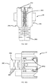
- FIG. 6 shows a communication tower, adapted to support and a flag (e.g. The American Flag), and having multiple antenna service bays covered by radio-transparent antenna bay cover shroud (i.e. shroud) panels which are each secured by several cellar communication tower panel security devices of the first illustrative embodiment of the present invention illustrated in FIGS. 61 through 22E ;
- a flag e.g. The American Flag
- radio-transparent antenna bay cover shroud i.e. shroud
- FIG. 6A shows a perspective enlarged view of the top portion of the communication tower illustrated in FIG. 6 ;
- FIG. 6B shows a perspective enlarged view of the communication tower panel security device of the first illustrative embodiment of the present invention mounted at about the upper end of the top most bay of the communication tower illustrated in FIG. 6 ;
- FIG. 6C is a partial cut-away perspective view of the communication tower panel security device shown in FIG. 6B ;
- FIG. 6D shows a perspective view of the cell tower structure of FIG. 6 , with the flag and its truck assembly removed from the top of the flag pole structure, as well as the shroud cover panels covering the top three bay sections of the cell tower structure, revealing antenna structures and associated electronics supported on the tower's supporting mast structure;
- FIG. 6E shows a perspective enlarged view of the topmost antenna structure mounted within the tower structure illustrated in FIG. 6D ;
- FIG. 6F shows a perspective view of the cell tower flag pole structure of FIGS. 6A through 1E , shown with its flag truck system removed and a set of communication tower panel security devices wrapped around the circumference of the communication tower structure at different height locations, to secure the panels in place against displacement in the presence of high winds and other foul weather conditions;
- FIG. 6G is a perspective view of the topmost communication tower panel security device illustrated in FIG. 6F , encircling and securing the topmost shroud panel of the communication tower;
- FIG. 6H shows a plan view of the communication tower panel security device of the first illustrative embodiment fastened the topmost portion of the communication tower illustrated in FIG. 6 ;
- FIG. 6I shows an elevated side view of the communication tower panel security device of the first illustrative embodiment fastened the topmost portion of the communication tower illustrated in FIG. 6G ;
- FIG. 6J shows a perspective side view of the communication tower panel security device of the first illustrative embodiment while fastened about the topmost portion of the communication tower illustrated in FIG. 6I ;
- FIG. 6K shows a plan view of the communication tower panel security device of the first illustrative embodiment, fastened about the topmost portion of the communication tower illustrated in FIG. 6I ;
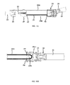
- FIG. 7A shows a first perspective side view of the connecting/tensioning assembly of the communication tower panel security device of the first illustrative embodiment displayed while removed from the communication tower illustrated in FIG. 6 ;
- FIG. 7B shows a first plan view of the connecting/tensioning assembly of the communication tower panel security device of the first illustrative embodiment, displayed while removed from the communication tower illustrated in FIG. 6 ;
- FIG. 7C shows a second plan view of the connecting/tensioning assembly of the communication tower panel security device of the first illustrative embodiment, flexibly configured for installation about a communication tower having a first diameter D 1 ;
- FIG. 7D shows a third plan view of the connecting/tensioning assembly of the communication tower panel security device of the first illustrative embodiment, flexibly configured for installation about a communication tower having a second diameter D 2 which is substantially smaller than tower diameter D 1 , and requiring that the device adapted to a dramatic curvature;
- FIG. 7E is a second perspective view of the connecting/tensioning assembly of the communication tower panel security device of the first illustrative embodiment displayed while removed from the communication tower illustrated in FIG. 6 ;
- FIG. 7F is a third perspective view of the connecting/tensioning assembly of the communication tower panel security device of the first illustrative embodiment displayed while removed from the communication tower illustrated in FIG. 6 ;
- FIG. 8A is a first exploded view of the communication tower panel security device of the first illustrative embodiment including its subcomponents comprising the connecting/tensioning assembly of the device, its flexible plastic tubing and cord subassembly fixed to the end connector, the first end module, the second end module, the pair of flexible side panels, and the sliding module configured and assembled as shown in FIGS. 7A through 7D ;
- FIG. 8B is a second exploded view of the communication tower panel security device of the first illustrative embodiment, including the subcomponents comprising the connecting/tensioning assembly of the device as well as the flexible plastic tubing, cord and other components;
- FIG. 9A is a perspective view of one of the flexible side panels employed in the communication tower panel security device of the first illustrative embodiment
- FIG. 9B is an elevated side view of one of the flexible side panels employed in the communication tower panel security device of the first illustrative embodiment
- FIG. 10A is a perspective exploded view of the first end module subassembly comprising the pair of flexible side panels, the first set of pulleys mounted in the first end module, and the first and second half sections forming the first end module;
- FIG. 10B is a first perspective view of the first end module shown assembled without the pair of flexible side panels, and its connector receiving portion adapted for receiving the connector attached to the flexible tubing and cord assembly during the device installation procedure of the present invention
- FIG. 10C is a second perspective view of the first end module shown assembled without the pair of flexible side panels, and its connector receiving portion adapted for receiving the connector attached to the flexible tubing and cord assembly during the device installation procedure of the present invention
- FIG. 10D is a first plan view of the first end module shown assembled without the pair of flexible side panels, and illustrating its cut tubing marking line realized as a relief-type raised line formed in the upper surface of the first end module, on the open channel side thereof;
- FIG. 10E is an elevated end view of the first end module shown assembled without the pair of flexible side panels, showing the open connector receiving channel;
- FIG. 10F is an elevated end view of the first end module shown assembled without the pair of flexible side panels, showing the end connector receiving channel;
- FIG. 10G is an elevated side view of the first end module shown assembled without the pair of flexible side panels, showing the side opening portion of the connector receiving channel;
- FIG. 11A is a first perspective view of the second end module employed in the communication tower panel security device of the first illustrative embodiment, showing its central opening, pair of flexible side panel receiving channels, shroud panel mounting surface, and excess cord windup fixture;
- FIG. 11B is a second perspective end view of the second end module employed in the communication tower panel security device of the first illustrative embodiment, showing its central opening, pair of flexible side panel receiving channels, shroud panel mounting surface, and the excess cord windup fixture;
- FIG. 11C is an elevated front view of the first end module showing its central opening, pair of flexible side panel receiving channels, shroud panel mounting surface, and the excess cord windup fixture;
- FIG. 11D is an elevated end view of the second end module showing its central opening, pair of flexible side panel receiving channels, shroud panel mounting surface, and the excess cord windup fixture;
- FIG. 11E is an elevated side view of the second end module
- FIG. 11F is an elevated front end view of the second end module
- FIG. 12A is a perspective exploded view of a subassembly comprising the second end module and the pair of flexible side panels;
- FIG. 12B is a perspective view of the subassembly of FIG. 12A shown comprising the second end module and the pair of flexible side panels assembled together;
- FIG. 12C is a first perspective partially fragmented view of the second end module and flexible side panels shown in FIG. 12B ;
- FIG. 12D is a second perspective partially fragmented view of the second end module and flexible side panels shown in FIGS. 12B and 12C ;
- FIG. 13A is a first perspective view of the sliding module employed in the communication tower panel security device of the first illustrative embodiment, showing its tubing connector, cord retaining mechanism, excess cord windup fixture and side panel support channels;
- FIG. 13B is a second perspective view of the sliding module employed in the communication tower panel security device of the first illustrative embodiment, showing its tubing connector, cord retaining mechanism, excess cord windup fixture and side panel support channels;
- FIG. 13C is a plan view of the sliding module employed in the communication tower panel security device of the first illustrative embodiment, showing its tubing connector, cord retaining mechanism, and excess cord windup fixture;
- FIG. 13D is an elevated side view of the sliding module employed in the communication tower panel security device of the first illustrative embodiment, showing its tubing connector, excess cord windup fixture and one of the side panel support channels;
- FIG. 13E is an elevated front view of the sliding module employed in the communication tower panel security device of the first illustrative embodiment, showing an axial view of the central cord passage port, the cord retaining mechanism, and excess cord windup fixture, and the side panel support channels;
- FIG. 13F is an elevated front view of the sliding module employed in the communication tower panel security device of the first illustrative embodiment, showing an axial view of the tubing connector, the cord retaining mechanism, and excess cord windup fixture, and the side panel support channels;
- FIG. 13G is an exploded view of the sliding module employed in the communication tower panel security device of the first illustrative embodiment, comprising a body or frame half portions that are joined together to form the body or frame portion of this component with a pair of rotatable cylindrical pulleys supported therebetween;
- FIG. 14A is a first perspective view of the cord/tubing connector shown assembled and comprising a channel engaging portion, a cord passage port, and a barbed tubing connector;
- FIG. 14B is a second perspective view of the cord/tubing connector of FIG. 14A showing its channel engaging portion, and barbed tubing connector;
- FIG. 14C is a plan view of the sliding module of FIGS. 13A and 13B showing its channel engaging portion and its barbed tubing connector;
- FIG. 14D is a first elevated side view of the cord/tubing connector of FIG. 14A showing its channel engaging portion, and barbed tubing connector;
- FIG. 14E is a first axial view of the cord/tubing connector of FIG. 14A showing its barbed tubing connector;
- FIG. 14F is a second axial view of the cord/tubing connector of FIG. 14A showing its channel engaging portion
- FIG. 14G is a perspective exploded view of the cord/tubing connector of FIGS. 14A through 14F , showing its first and second half portions and interior structures including a central post about which the routed cord can be securely tied;
- FIG. 15A is a plan view of an assembled communication tower panel security device of the first illustrative embodiment with its end connector interconnected to the first end module, and cord routing points P 1 and P 2 indicated where the cord enters and exits the connecting/tensioning module of the device;
- FIG. 15B is a perspective view of the sliding module showing its central cord output input port at point P 2 , central cord output port at point P 3 , its lower cord input and output ports at points P 6 and P 7 , and its upper cord input and output ports at points P 10 and P 11 ;
- FIG. 15C is a perspective view of the second end module showing its left cord input and output ports at points P 4 and P 5 , and its right cord input and output ports at points P 8 and P 9 ;
- FIG. 15D is a plan cross-sectional view of the end connector module interconnected with the second end module, showing the cord being tied and secured about the central post within the end connector module at points P 1 and P. 1 ;
- FIG. 15E is a cross-sectional view of the sliding module mounted within the flexible side panels, showing the cord pathway from the central cord input port at point P 2 , then routed long pathway points P 2 . 1 , P 2 . 2 , P 2 . 3 , P 2 . 4 , P 2 . 5 , P 2 . 6 and P 2 . 3 , as shown;
- FIG. 15F is a plan view of the connecting/tensioning module showing the cord routed from central cord output port at point 3 to left side cord input port at point P 4 ;
- FIG. 15G is a cross section view of the second end module and connector module, showing the cord routed from the left cord input and output ports at point P 4 to P 5 , around the pulley cylinder at point P 4 . 1 ;
- FIG. 15H is a plan view of the connecting/tensioning module, showing the cord being routed from point P 5 at the second end module to point P 6 at the sliding module;
- FIG. 15I is a plan view of the sliding module within the connecting/tensioning module, showing the cord being routed from cord input point P 6 , about the first pulley at point P 6 . 1 , to cord output point P 7 ;
- FIG. 15J is a plan view of the connecting/tensioning module, showing the cord being routed from point P 7 at the sliding module to point P 8 at the second end module;
- FIG. 15K is a plan view of the second end module within the connecting/tensioning module, showing the cord being routed from cord input point P 8 , about the second pulley at point P 8 . 1 , to cord output point P 9 ;
- FIG. 15L is a plan view of the connecting/tensioning module, showing the cord being routed from point P 9 at the second end module to point P 10 at the sliding module;
- FIG. 15M is a plan view of the sliding module within the connecting/tensioning module, showing the cord being routed from cord input point P 10 , about the second pulley at point P 10 . 1 , to cord output point P 11 ;
- FIG. 16A is a perspective view of the top bay of the communication tower, about which the communication tower panel security device of the first illustrative embodiment is being aligned with a pre-affixed Velcro fastening patch applied to the mounting surface of the shroud panel associated with the antenna bay of the communication tower;
- FIG. 16B is a perspective view of the communication tower panel security device of the first illustrative embodiment being brought closed to an aligned pre-affixed Velcro fastening patch applied to the mounting surface of the shroud panel of the communication tower;
- FIG. 16C is a perspective partially fragmented view of the communication tower, showing the communication tower panel security device of the first illustrative embodiment mounted to the pre-affixed Velcro fastening patch applied to the mounting surface of the shroud panel of the communication tower;
- FIG. 16D is a perspective view of the communication tower panel security device of the first illustrative embodiment mounted to the pre-affixed Velcro fastening patch applied to the mounting surface of the shroud panel of the communication tower;
- FIG. 16E is a perspective view of the top bay of the communication tower, about which the connecting/tensioning module of the communication tower panel security device of the first illustrative embodiment is mounted to a Velcro fastener affixed to a shroud panel associated with the communication tower, and where the free end connector is being slidably connected to the connector channel of the second end module;
- FIG. 16F is a plan view of the free connector end of the communication tower panel security device of the first illustrative embodiment being connected to the mounting surface of the shroud panel of the communication tower;
- FIG. 16G is a first perspective closer view showing the end connector module being slid into the connector channel provided on the rear end portion of the second end module of the first illustrative embodiment of the present invention
- FIG. 16H is a second perspective closer view showing the end connector module slid fully into the connector channel provided on the rear end portion of the second end module of the first illustrative embodiment of the present invention
- FIG. 17A is a perspective view of the top bay of the communication tower, about which the connecting/tensioning module of the communication tower panel security device of the first illustrative embodiment is mounted with the free end connector connected into the connector channel of the second end module, where the sliding module is located closely to the first end module and the cord is arranged in its loose configuration;
- FIG. 17B is a perspective view of the connecting/tensioning module of the communication tower panel security device of the first illustrative embodiment shown removed from the communication tower of FIG. 17A ;
- FIG. 18A is a perspective view of the connecting/tensioning module of the communication tower panel security device of the first illustrative embodiment mounted on the communication tower of FIG. 17A , wherein during the first step of the cord tensioning process, the cord from the sliding module is pulled upwardly, causing the cord to tighten and the sliding module to slide closer towards the second end module;
- FIG. 18A-1 is a cross-sectional view of the connecting/tensioning module of the communication tower panel security device of the first illustrative embodiment shown in FIG. 18A ;
- FIG. 18B is a perspective view of the connecting/tensioning module of the communication tower panel security device of the first illustrative embodiment shown removed from the communication tower of FIG. 17A , wherein during the second step of the cord tensioning process, the cord from the sliding module is pulled further upwardly, causing the cord to further tighten and the sliding module to slide even closer towards the second end module;
- FIG. 19A is a perspective view of the connecting/tensioning module of the communication tower panel security device of the first illustrative embodiment shown mounted on the communication tower of FIG. 17A , wherein during the third step of the cord tensioning process, the tightened cord is pulled back through the cord retaining mechanism on the top of the sliding module and locked into place therein;
- FIG. 19B is a perspective view of the connecting/tensioning module of the communication tower panel security device of the first illustrative embodiment shown mounted on the communication tower of FIG. 17A , wherein during the third step of the cord tensioning process, the tightened cord is pulled back through the cord retaining mechanism on the top of the sliding module and locked into place therein, as shown, and where excess cord can thereafter we wound up during a subsequent cord handling step;
- FIG. 19C is a perspective view of the connecting/tensioning module of the communication tower panel security device of the first illustrative embodiment as shown and configured in FIG. 19B ;
- FIG. 19D is a perspective view of the connecting/tensioning module of the communication tower panel security device of the first illustrative embodiment as shown and configured in FIG. 19C , where the excess cord is drawn and prepared to be wrapped around the excess cord wrapping fixtures supported by the device;
- FIG. 20A is a plan view of the connecting/tensioning module of the communication tower panel security device shown and configured in FIG. 19D , where the excess cord has been wrapped around the excess cord wrapping fixtures supported by the device;
- FIG. 20B is a perspective view of the connecting/tensioning module of the communication tower panel security device shown and configured in FIG. 20A , where the excess cord has been wrapped around the excess cord wrapping fixtures supported by the device;
- FIG. 21A is a perspective view of the connecting/tensioning module of the communication tower panel security device shown and configured in FIGS. 20A and 20B , where the excess cord has been wrapped around the excess cord wrapping fixtures supported by the device, and the free end of the cord retained in a second cord retaining mechanism supported on the first end module;
- FIG. 21B is a plan view of the connecting/tensioning module of the communication tower panel security device shown and configured in FIG. 20A , where the excess cord has been wrapped around the excess cord wrapping fixtures supported by the device, and the free end of the cord retained in a second cord retaining mechanism supported on the first end module;
- FIG. 22A is a perspective view of the communication tower panel security device of the first illustrative embodiment shown installed and configured about a communication tower having a first outer diameter D 1 , where the connecting/tensioning housing has flexed and closely adapted the radius of curvature of the shroud panels of the communication tower to provide a tight fit thereabout;
- FIG. 22B is a plan view of the communication tower and communication tower panel security device of the first illustrative embodiment shown in FIG. 22A ;
- FIG. 22C is a perspective view of the communication tower and communication tower panel security device of the first illustrative embodiment shown in FIG. 22A , having a radius of curvature D 1 ;
- FIG. 22D is a perspective view of the communication tower panel security device of the first illustrative embodiment shown installed and configured about a communication tower having a second outer diameter D 2 , which is much smaller than diameter D 1 , where the connecting/tensioning housing has flexed and closely adapted the radius of curvature of the shroud panels of the communication tower to provide a tight fit thereabout;
- FIG. 22E is a perspective view of the communication tower and communication tower panel security device of the first illustrative embodiment shown in FIG. 22A , having a shorter radius of curvature D 2 (D 1 ⁇ D 2 );
- FIG. 23A is an elevated side view of a cellular communication tower (CCT) equipped with multiple communication tower panel security devices according to the second illustrative embodiment of the present invention, illustrated in FIGS. 23B through 26C-2 ;
- CCT cellular communication tower
- FIG. 23B is a perspective view of the communication tower panel security device of the second illustrative embodiment fastened to an antenna bay of a communication tower, and secured tightly thereabout;
- FIG. 24 is an exploded view of the communication tower panel security device of the second illustrative embodiment of the present invention.
- FIG. 25 is a perspective view of the communication tower panel security device of the second illustrative embodiment of the present invention, shown removed from the communication tower;
- FIG. 26A is a perspective view of the communication tower panel security device of the second illustrative embodiment of the present invention, showing the end strap being slid into the connecting/tensioning assembly of the device of the present invention;
- FIG. 26B is a perspective, partially cutaway view of the communication tower panel security device of the second illustrative embodiment of the present invention, showing the end strap slid into and engaged by connecting/tensioning assembly of the device, so that the device surrounds and secures the shroud panels of the communication tower;
- FIG. 26B-1 is an elevated cross-sectional view of the connecting/tensioning assembly of the communication tower panel security device of the second illustrative embodiment of the present invention shown in FIG. 26B ;
- FIG. 26C is a perspective view of the communication tower panel security device of the second illustrative embodiment of the present invention, showing its end strap slid into and engaged by connecting/tensioning assembly of the device and the device fully tightened so that the it fully surrounds and secures certain shroud panels of the communication tower;
- FIG. 26C-1 is a perspective partially fragmented view of the connecting/tensioning assembly of the communication tower panel security device of the second illustrative embodiment of the present invention shown in FIG. 26C ;
- FIG. 26C-2 is an elevated cross-sectional view of the connecting/tensioning assembly of the communication tower panel security device of the second illustrative embodiment of the present invention shown in FIG. 26C-1 ;
- FIG. 27A is an elevated side view of a cellular communication tower (CCT) equipped with multiple communication tower panel security devices according to the third illustrative embodiment of the present invention, illustrated in FIGS. 27B through 29E ;
- CCT cellular communication tower
- FIG. 27B is a perspective view of the communication tower panel security device of the third illustrative embodiment fastened to an antenna bay of a communication tower, and secured tightly thereabout;
- FIG. 28 is an exploded view of the communication tower panel security device of the third illustrative embodiment of the present invention.
- FIG. 29A is a perspective view of the communication tower panel security device of the third illustrative embodiment of the present invention, showing the end connector being inserted into the connector channel of the connecting/tensioning assembly of the device of the second embodiment of the present invention, so that the device surrounds and secures the shroud panels of the communication tower;
- FIG. 29B is a perspective view of the communication tower panel security device of the third illustrative embodiment of the present invention, showing the tensioning handle lifted up and disposed in the crank and tighten position;
- FIG. 29C is a first perspective view of the communication tower panel security device of the third illustrative embodiment of the present invention, showing with the tensioning handle arranged in the pushed down cord-tightened position;
- FIG. 29D is a second perspective view of the communication tower panel security device of the third illustrative embodiment of the present invention, showing with the tensioning handle arranged in the pushed down cord-tightened position;
- FIG. 29E is a cross-sectional view of the communication tower panel security device of the third illustrative embodiment of the present invention, shown with its tensioning handle arranged in the pushed down cord-tightened position, and the plastic casing removed from the connecting/tensioning assembly;
- FIG. 30 is an elevated side view of a cellular communication tower (CCT) equipped with multiple communication tower panel security devices according to the fourth illustrative embodiment of the present invention, illustrated in FIGS. 31 through 34C ;
- CCT cellular communication tower
- FIG. 31 is a perspective view of the communication tower panel security device of the fourth illustrative embodiment that is fastened to an antenna bay of a communication tower shown in FIG. 30 , and secured tightly thereabout;
- FIG. 32 is an exploded view of the communication tower panel security device of the fourth illustrative embodiment of the present invention, shown in FIG. 31 ;
- FIG. 33A is a perspective view of the communication tower panel security device of the fourth illustrative embodiment of the present invention, showing its flat pronged end connector being slid into the connector channel of the connecting/tensioning assembly of the device, and the free end of the cord is routed about the pulley within the connected/winding module, so that the device can surround and secures the shroud panels of the communication tower;
- FIG. 33B is a first perspective view of the communication tower panel security device of the fourth illustrative embodiment of the present invention, where its flat pronged end connector is slid into the connector channel of the connecting/tensioning assembly of the device, and the free end of the cord has been pulled through the pulley within the connected/winding module, so that the cord and plastic tubing encasing the same surrounds and secures the shroud panels of the communication tower under a desired degree of tension;
- FIG. 33C is a second perspective view of the communication tower panel security device of the fourth illustrative embodiment of the present invention, shown in FIG. 33B ;
- FIG. 34 is an elevated side view of the communication tower panel security device of the fourth illustrative embodiment of the present invention, where the flat pronged end connector has slid further along the connector channel of the connecting/tensioning assembly of the device, and the free end of the cord has been further pulled through the pulley within the connected/winding module, so that the cord and plastic tubing encasing the same surrounds and secures the shroud panels of the communication tower under a desired degree of tension, while the ratchet mechanism locks the tensioned cord in position;
- FIG. 35 is an elevated side view of a cellular communication tower (CCT) equipped with multiple communication tower panel security devices according to the fifth illustrative embodiment of the present invention, illustrated in FIGS. 31 through 34 ;
- CCT cellular communication tower
- FIG. 36 is a perspective view of the communication tower panel security device of the fifth illustrative embodiment that is fastened to an antenna bay of a communication tower shown in FIG. 35 , and secured tightly thereabout;
- FIG. 37 is an exploded view of the communication tower panel security device of the fifth illustrative embodiment of the present invention, shown in FIG. 35 ;
- FIG. 38A is a perspective view of the communication tower panel security device of the fifth illustrative embodiment of the present invention, showing its flat dented end connector being slid into the connector channel of the connecting/tensioning assembly of the device so that the device can surround and secure the shroud panels of the communication tower;
- FIG. 38B is a perspective view of the communication tower panel security device of the fifth illustrative embodiment of the present invention, where its flat dented end connector is manually slid into and along the connector channel of the connecting/tensioning assembly of the device, so that the plastic tubing encasing the same surrounds and is taught about the shroud panels of the communication tower;
- FIG. 38C is a second perspective view of the communication tower panel security device of the fifth illustrative embodiment of the present invention, shown in FIG. 38B , where the tightening bar is rotated multiple times, each time, further advancing the dented end connector along the connector channel of the connecting/tensioning assembly of the device, so that the plastic tubing secures the shroud panels of the communication tower under a desired degree of tension; and;
- FIG. 38D is a perspective view of the communication tower panel security device of the fifth illustrative embodiment of the present invention, as shown in FIG. 38C , but where the tightening bar is shown disposed in its half-rotated position;
- FIG. 38E is an elevated cross-sectional view of the communication tower panel security device of the fifth illustrative embodiment of the present invention, shown in FIG. 38D ;
- FIG. 38F is a perspective view of the communication tower panel security device of the fifth illustrative embodiment of the present invention, as shown in FIG. 38E , but where the un-tightening bar is shown being rotated in the clockwise direction, pushing the dented end connector in the reverse direction so as to decrease the tension of the device about the communication tower;
- FIG. 38G is a perspective view of the communication tower panel security device of the fifth illustrative embodiment of the present invention, as shown in FIG. 38F , where the un-tightening bar is shown being fully rotated in the clockwise direction, pushing the dented end connector in the reverse direction by a predetermined amount;
- FIG. 39 is an elevated side view of a cellular communication tower (CCT) equipped with multiple communication tower panel security devices according to the sixth illustrative embodiment of the present invention, illustrated in FIGS. 40 through 44B ;
- CCT cellular communication tower
- FIG. 40A is a perspective view of the communication tower panel security device of the sixth illustrative embodiment that is fastened to an antenna bay of a communication tower shown in FIG. 39 , and secured tightly thereabout;
- FIG. 40B is a perspective view of the communication tower panel security device of the sixth illustrative embodiment of the present invention, shown in FIG. 40A ;
- FIG. 41 is an exploded view of the communication tower panel security device of the sixth illustrative embodiment of the present invention, shown in FIG. 40A , showing its flexible band structure, its connecting/tensioning assembly with its first connection channel and second pass-though connection channel, and its spring-loaded cam component rotatably mounted along the pass-though connection channel;
- FIG. 42A is a perspective view of the communication tower panel security device of the sixth illustrative embodiment of the present invention, shown removed from the communication tower, with one free end of the flexible banding structure mounted within the mated connection channel, while the other free end of the flexible banding structure is removed and disengaged from its connection channel;
- FIG. 42B is a perspective view of the communication tower panel security device of the sixth illustrative embodiment of the present invention, shown removed from the communication tower, with one free end of the flexible banding structure mounted within the mated connection channel, while the other free end of the flexible banding structure slid through, and engaged with the engaging cam component mounted along the pass-through connection channel;
- FIG. 43A is a perspective view of the communication tower panel security device of the sixth illustrative embodiment of the present invention, shown in FIG. 41 with its connecting/tensioning assembly fastened to the surface of a shroud panel on a communication tower using Velcro fasteners, with the flexible banding structure wrapped around the tower but the free end thereof not yet inserted with the pass-through connection channel within the connecting/tensioning assembly;
- FIG. 43B is an elevated cross-sectional view of the communication tower panel security device of the sixth illustrative embodiment shown in FIG. 43A , taken along line 43 B- 43 B shown in FIG. 43A ;
- FIG. 44A is a perspective view of the communication tower panel security device of the sixth illustrative embodiment of the present invention, shown in FIG. 41 with its connecting/tensioning assembly fastened to the surface of a shroud panel on a communication tower using Velcro fasteners, and the flexible banding structure wrapped around the tower and its free end thereof inserted through the pass-through connection channel within the connecting/tensioning assembly, and engaged by its engaging cam component;
- FIG. 44B is an elevated cross-sectional view of the communication tower panel security device of the sixth illustrative embodiment shown in FIG. 44A , taken along line 44 B- 44 B shown in FIG. 44A ;
- FIG. 45 is an elevated side view of a cellular communication tower (CCT) equipped with multiple communication tower panel security devices according to the seventh illustrative embodiment of the present invention, illustrated in FIGS. 46A through 50B ;
- CCT cellular communication tower
- FIG. 46A is a perspective view of the communication tower panel security device of the seventh illustrative embodiment that is fastened to an antenna bay of a communication tower shown in FIG. 45 , and secured tightly thereabout;
- FIG. 46B is a perspective view of the communication tower panel security device of the seventh illustrative embodiment shown removed from an antenna bay of a communication tower illustrated in FIG. 45 ;
- FIG. 47 is an exploded view of the communication tower panel security device of the seventh illustrative embodiment of the present invention, shown in FIG. 45 , showing its flexible band structure, its connecting/tensioning assembly with its first connection channel and second pass-though connection channel, and its spring-loaded ratchet component rotatably mounted along the pass-though connection channel;
- FIG. 48A is a perspective view of the communication tower panel security device of the seventh illustrative embodiment of the present invention, shown removed from the communication tower, with one free end of the flexible banding structure mounted within the mated connection channel, while the other free end of the flexible banding structure is removed and disengaged from its connection channel;
- FIG. 48B is a cross sectional view of the communication tower panel security device of the seventh illustrative embodiment of the present invention, taken along line 48 B- 48 B in FIG. 48A ;
- FIG. 49A is a perspective view of the communication tower panel security device of the seventh illustrative embodiment of the present invention, shown in FIG. 45 with its connecting/tensioning assembly fastened to the surface of a shroud panel on a communication tower using Velcro fasteners, with the flexible banding structure wrapped around the tower but the free end thereof not yet inserted with the pass-through connection channel within the connecting/tensioning assembly;
- FIG. 49B is an elevated cross-sectional view of the communication tower panel security device of the seventh illustrative embodiment shown in FIG. 45 , taken along line 49 B- 49 B shown in FIG. 49A ;
- FIG. 50A is a perspective view of the communication tower panel security device of the seventh illustrative embodiment of the present invention, shown in FIG. 45 with its connecting/tensioning assembly fastened to the surface of a shroud panel on a communication tower using Velcro fasteners, and the flexible banding structure wrapped around the tower and its free end thereof inserted through the pass-through connection channel within the connecting/tensioning assembly, and engaged by its engaging cam component;
- FIG. 50B is an elevated cross-sectional view of the communication tower panel security device of the seventh illustrative embodiment shown in FIG. 50A , taken along line 50 B- 50 B shown in FIG. 50A ;
- FIG. 51 is an elevated side view of a cellular communication tower (CCT) equipped with multiple communication tower panel security devices according to the eighth illustrative embodiment of the present invention, illustrated in FIGS. 52 through 56B ;
- CCT cellular communication tower
- FIG. 52A is a perspective view of the communication tower panel security device of the eighth illustrative embodiment that is fastened to an antenna bay of a communication tower shown in FIG. 45 , and secured tightly thereabout;
- FIG. 52B is a first perspective view of the communication tower panel security device of the eighth illustrative embodiment shown removed from an antenna bay of a communication tower illustrated in FIG. 51 ;
- FIG. 52C is a second perspective view of the communication tower panel security device of the eighth illustrative embodiment shown removed from an antenna bay of a communication tower illustrated in FIG. 51 ;
- FIG. 53 is an exploded view of the communication tower panel security device of the eighth illustrative embodiment of the present invention, shown in FIG. 51 , showing its flexible tube structure, its connecting/tensioning assembly with its first connection channel and second pass-though connection channel disposed in different planes, and its spring-loaded locking component axially mounted along the pass-though connection channel;
- FIG. 54A is a perspective view of the communication tower panel security device of the eighth illustrative embodiment of the present invention, shown removed from the communication tower, with one free end of the flexible tube structure mounted within the mated connection channel, while the other free end of the flexible tube structure is removed and disengaged from its connection channel;
- FIG. 54B is a cross sectional view of the communication tower panel security device of the eighth illustrative embodiment of the present invention, taken along line 54 B- 54 B in FIG. 54A ;
- FIG. 55A is a perspective view of the communication tower panel security device of the eighth illustrative embodiment of the present invention, shown in FIG. 51 with its connecting/tensioning assembly fastened to the surface of a shroud panel on a communication tower using Velcro fasteners, with the flexible tube structure wrapped around the tower but the free end thereof not yet inserted with the pass-through connection channel within the connecting/tensioning assembly;
- FIG. 55B is an elevated cross-sectional view of the communication tower panel security device of the eighth illustrative embodiment shown in FIG. 51 taken along line 55 B- 55 B shown in FIG. 55A , showing how the connection channels are disposed in different planes relative to the earth's plane when mounted on a communication tower;
- FIG. 56A is a perspective view of the communication tower panel security device of the eighth illustrative embodiment of the present invention, shown in FIG. 51 with its connecting/tensioning assembly fastened to the surface of a shroud panel on a communication tower using Velcro fasteners, and the flexible tube structure wrapped around the tower and its free end thereof inserted through the pass-through connection channel within the connecting/tensioning assembly, and engaged by its engaging cam component;
- FIG. 56B is an elevated cross-sectional view of the communication tower panel security device of the eighth illustrative embodiment shown in FIG. 56A , taken along line 56 B- 56 B shown in FIG. 56A ;
- FIG. 57 is an elevated side view of a cellular communication tower (CCT) equipped with multiple communication tower panel security devices according to the ninth illustrative embodiment of the present invention, illustrated in FIGS. 58A through 62B ;
- CCT cellular communication tower
- FIG. 58A is a perspective view of the communication tower panel security device of the ninth illustrative embodiment that is fastened to an antenna bay of a communication tower shown in FIG. 45 , and secured tightly thereabout;
- FIG. 58B is a first perspective view of the communication tower panel security device of the ninth illustrative embodiment shown removed from an antenna bay of a communication tower illustrated in FIG. 57 ;
- FIG. 58C is a second perspective view of the communication tower panel security device of the ninth illustrative embodiment shown removed from an antenna bay of a communication tower illustrated in FIG. 57 ;
- FIG. 59 is an exploded view of the communication tower panel security device of the ninth illustrative embodiment of the present invention, shown in FIG. 57 , showing its flexible tube structure, its connecting/tensioning assembly with its first connection channel and second pass-though connection channel disposed in substantially the same plane relative to the Earth's horizontal plane, and its spring-loaded locking component axially mounted along the pass-though connection channel;
- FIG. 60A is a perspective view of the communication tower panel security device of the ninth illustrative embodiment of the present invention, shown removed from the communication tower, with one free end of the flexible tube structure mounted within the mated connection channel, while the other free end of the flexible tube structure is removed and disengaged from its connection channel;
- FIG. 60B is a cross sectional view of the communication tower panel security device of the ninth illustrative embodiment of the present invention, taken along line 60 B- 60 B in FIG. 60A , showing how the connection channels are disposed in substantially the same plane relative to the earth's horizontal plane when mounted on a communication tower;
- FIG. 61A is a perspective view of the communication tower panel security device of the ninth illustrative embodiment of the present invention, shown in FIG. 57 with its connecting/tensioning assembly fastened to the surface of a shroud panel on a communication tower using Velcro fasteners, with the flexible tube structure wrapped around the tower but the free end thereof not yet inserted with the pass-through connection channel within the connecting/tensioning assembly;
- FIG. 61B is an elevated cross-sectional view of the communication tower panel security device of the ninth illustrative embodiment shown in FIG. 57 taken along line 61 B- 61 B shown in FIG. 55A ;
- FIG. 62A is a perspective view of the communication tower panel security device of the ninth illustrative embodiment of the present invention, shown in FIG. 57 with its connecting/tensioning assembly fastened to the surface of a shroud panel on a communication tower using Velcro fasteners, and the flexible tube structure wrapped around the tower and its free end thereof inserted through the pass-through connection channel within the connecting/tensioning assembly, and engaged by its engaging cam component;
- FIG. 62B is an elevated cross-sectional view of the communication tower panel security device of the ninth illustrative embodiment shown in FIG. 62A , taken along line 62 B- 62 B shown
- FIG. 63 is an elevated side view of a cellular communication tower (CCT) equipped with multiple communication tower panel security devices according to the tenth illustrative embodiment of the present invention, illustrated in FIGS. 64 through 68B ;
- CCT cellular communication tower
- FIG. 64A is a perspective view of the communication tower panel security device of the tenth illustrative embodiment that is fastened to an antenna bay of a communication tower shown in FIG. 45 , and secured tightly thereabout;
- FIG. 64B is a first perspective view of the communication tower panel security device of the tenth illustrative embodiment shown removed from an antenna bay of a communication tower illustrated in FIG. 63 ;
- FIG. 64C is a second perspective view of the communication tower panel security device of the tenth illustrative embodiment shown removed from an antenna bay of a communication tower illustrated in FIG. 63 ;
- FIG. 65 is an exploded view of the communication tower panel security device of the tenth illustrative embodiment of the present invention, shown in FIG. 63 , showing its flexible tube structure, its connecting/tensioning assembly with its first connection channel and second pass-though connection channel, and its spring-loaded locking component axially mounted along the pass-though connection channel;
- FIG. 66A is a perspective view of the communication tower panel security device of the tenth illustrative embodiment of the present invention, shown removed from the communication tower, with one free end of the flexible tube structure mounted within the mated connection channel, while the other free end of the flexible tube structure is removed and disengaged from its connection channel;
- FIG. 66B is a cross sectional view of the communication tower panel security device of the tenth illustrative embodiment of the present invention, taken along line 66 B- 66 B in FIG. 6A ;
- FIG. 67A is a perspective view of the communication tower panel security device of the tenth illustrative embodiment of the present invention, shown in FIG. 63 with its connecting/tensioning assembly fastened to the surface of a shroud panel on a communication tower using Velcro fasteners, with the flexible tube structure wrapped around the tower but the free end thereof not yet inserted with the pass-through connection channel within the connecting/tensioning assembly;
- FIG. 67B is an elevated cross-sectional view of the communication tower panel security device of the tenth illustrative embodiment shown in FIG. 63 taken along line 67 B- 67 B shown in FIG. 67A ;
- FIG. 68A is a perspective view of the communication tower panel security device of the tenth illustrative embodiment of the present invention, shown in FIG. 63 with its connecting/tensioning assembly fastened to the surface of a shroud panel on a communication tower using Velcro fasteners, and the flexible tube structure wrapped around the tower and its free end thereof inserted through the pass-through connection channel within the connecting/tensioning assembly, and engaged by its engaging cam component;
- FIG. 68B is an elevated cross-sectional view of the communication tower panel security device of the tenth illustrative embodiment shown in FIG. 68A , taken along line 68 B- 68 B shown in FIG. 68A ;
- FIG. 69 is an elevated side view of a cellular communication tower (CCT) equipped with multiple communication tower panel security devices according to the eleventh illustrative embodiment of the present invention, illustrated in FIGS. 70A through 74B ;
- CCT cellular communication tower
- FIG. 70A is a perspective view of the communication tower panel security device of the eleventh illustrative embodiment that is fastened to an antenna bay of a communication tower shown in FIG. 69 , and secured tightly thereabout;
- FIG. 70B is a first perspective view of the communication tower panel security device of the eleventh illustrative embodiment shown removed from an antenna bay of a communication tower illustrated in FIG. 69 ;
- FIG. 71 is an exploded view of the communication tower panel security device of the eleventh illustrative embodiment of the present invention, shown in FIG. 69 , showing its flexible banding structure, and its connecting/tensioning assembly comprising a pair of connection blocks secured near the free ends of the flexible banding structure (e.g. about 5-8 inches from the ends thereof), and Velcro® brand based releasable fastening mechanism coupling these connection blocks to provide the desired degree of tension;
- FIG. 72A is a perspective view of the communication tower panel security device of the eleventh illustrative embodiment of the present invention, shown being wrapped about a communication tower to be secured, with one free end of the flexible banding structure being brought in close proximity to the other free end of the flexible banding, to thread the Velcro fastening strip (e.g. band) between the pair of connection blocks securely mounted near these free ends;
- the Velcro fastening strip e.g. band
- FIG. 72B is a cross sectional view of the communication tower panel security device of the eleventh illustrative embodiment of the present invention, taken along line 72 B- 72 B in FIG. 72A ;
- FIG. 73A is a perspective view of the communication tower panel security device of the eleventh illustrative embodiment of the present invention, shown completely wrapped about a communication tower to be secured, with one free end of the flexible banding structure in close proximity to the other free end of the flexible banding, and the Velcro fastening strip (e.g. band) threaded between the pair of connection blocks securely mounted near these free ends and being adjusted so as to create the required degree of tension in the flexible banding structure to secure the communication tower shroud/cover panels;
- Velcro fastening strip e.g. band
- FIG. 73B is a cross sectional view of the communication tower panel security device of the eleventh illustrative embodiment of the present invention, taken along line 73 B- 73 B in FIG. 73A ;
- FIG. 74A is a perspective view of the communication tower panel security device of the eleventh illustrative embodiment of the present invention, shown completely wrapped about a communication tower to be secured, with the flexible banding structure fully connected and tensioned by the Velcro fastening strip (e.g. band) threaded between the pair of connection blocks, and tightly wrapping around the communication tower shroud/cover panels;
- the Velcro fastening strip e.g. band
- FIG. 74B is a cross sectional view of the communication tower panel security device of the eleventh illustrative embodiment of the present invention, taken along line 74 B- 74 B in FIG. 74A ;
- FIG. 75 is an elevated side view of a cellular communication tower (CCT) equipped with multiple communication tower panel security devices according to the twelfth illustrative embodiment of the present invention, illustrated in FIGS. 76 through 34C ;
- CCT cellular communication tower
- FIG. 76 is a perspective view of the communication tower panel security device of the twelfth illustrative embodiment that is fastened to an antenna bay of a communication tower shown in FIG. 75 , and secured tightly thereabout;
- FIG. 77 is an exploded view of the communication tower panel security device of the twelfth illustrative embodiment of the present invention, shown in FIG. 75 , showing its flexible banding structure, and its connecting/tensioning assembly comprising a thin but strong strap (with Velcro end strips) that slides into and along a central track formed along the outer surface of the flexible banding structure, and then buckled together using a conventional strap buckling device, to provide the desired degree of tension;
- a thin but strong strap with Velcro end strips
- FIG. 78A is a perspective view of the communication tower panel security device of the twelfth illustrative embodiment of the present invention, shown removed from the communication tower, where the free ends of the flexible plastic banding structure are brought into proximity of each other, so that its connecting/tensioning assembly (comprising a thin but strong strap (with Velcro end strips) that slides into and along a central track formed along the outer surface of the flexible banding structure while its free ends are buckled together using a conventional strap buckling device) can generates the required degree of tension around the shroud panels around the communication tower;
- a thin but strong strap with Velcro end strips
- FIG. 78B is a perspective view of the communication tower panel security device of the twelfth illustrative embodiment of the present invention, shown removed from the communication tower, where the free ends of the flexible plastic banding structure are buckled together using the strap-based connecting/tensioning assembly, to generate the desired degree of tension around the shroud panels around the communication tower;
- FIG. 78C is a perspective view of the communication tower panel security device of the twelfth illustrative embodiment of the present invention, shown removed from the communication tower, where the free ends of the flexible plastic banding structure are overlapping and buckled together using the strap-based connecting/tensioning assembly, to generate the desired degree of tension around the shroud panels around the communication tower;
- FIG. 79A is a perspective view of the communication tower panel security device of the twelfth illustrative embodiment of the present invention being installed about a communication tower, showing the free ends of the flexible plastic banding structure being brought into proximity of each other, so that its connecting/tensioning assembly (comprising a thin but strong strap (with Velcro end strips) that slides into and along a central track formed along the outer surface of the flexible banding structure while its free ends are buckled together using a conventional strap buckling device) can generate the required degree of tension around the shroud panels around the communication tower;
- a thin but strong strap with Velcro end strips
- FIG. 79B is a perspective view of the communication tower panel security device of the twelfth illustrative embodiment of the present invention being installed about a communication tower, showing its flexible plastic banding structure wrapped around the communication tower, and its strap-based connecting/tensioning assembly being buckled together using a conventional strap buckling device, to provide the desired degree of tension around the shroud panels around the communication tower; and
- FIG. 79C is a perspective view of the communication tower panel security device of the twelfth illustrative embodiment of the present invention being installed about a communication tower, showing its flexible plastic banding structure wrapped around the communication tower, with its free ends overlapping each other, while its strap-based connecting/tensioning assembly is buckled together using a conventional strap buckling device, to provide the desired degree of tension around the shroud panels around the communication tower.
- FIG. 6 shows a communication tower 10 constructed and adapted according to the principles of the present invention, wherein a flag (e.g. The American Flag) 11 is supported in proud, safe and secure manner.
- the communication tower 10 has multiple bays 12 A through 12 D covered by radio-transparent shroud panels 13 which are each secured by several cellar communication tower panel security devices 14 , constructed in accordance with the first illustrative embodiment of the present invention, illustrated in great detail in FIGS. 61 through 22E .
- the upper section of the communication tower has several antenna/service bays about which multiple communication tower panel security devices 14 are mounted.
- the upper end of the top most bay of the communication tower illustrated supports a flag truck assembly 15 for supporting the flag 11 .
- the flag truck assembly 15 is removed from the top of the flag pole structure for purposes of illustration.
- the communication tower panel security device 14 is shown installed about the upper section of the top bay of the communication tower 10 , while arranged in its closed and tensioned configuration.
- FIG. 6D As shown in FIG. 6D , all of the shroud cover panels 13 are shown removed from the four uppermost antenna service bays, revealing the antenna structures 17 and associated electronics supported on the tower's supporting mast structure 18 , with cylindrical shroud cover support fixture discs 18 A.
- FIG. 6E provides an enlarged view of the topmost antenna structure mounted within the tower structure illustrated in FIG. 6D .
- antenna structures and configurations that appears in wireless communication towers, on which the communication tower panel security devices are installed will typically vary from wireless communication tower installation, and most cellular communication towers will contain antennas associated with different kinds of deployed digital cellular communication networks. Also, it is understood that the bandwidth of electromagnetic signal operation of any particular transmitting and/or receiving antenna structure, supported on any communication tower mast structure, will depend on the type of wireless telecommunication network in which the antenna structure is functioning.
- GSM Global System For Mobile Communications
- GPRS General Packet Radio Service
- cdmaOne Interim Standard 95 or IS-95, the first CDMA-based digital cellular (2G) standard by Qualcomm
- CDMA2000 Evolution-Data Optimized
- EDGE Enhanced Data Rates for GSM Evolution
- UMTS Universal Mobile Telecommunication System
- DECT Digital Enhanced Cordless Telecommunications
- iDEN Integrated Digital Enhanced Network
- the cell tower flag pole structure of FIG. 6A has its flag truck system 15 removed and a set of communication tower panel security devices 14 are tightly wrapped around the circumference of the communication tower structure at different height locations, to secure the shroud (cover) panels in place against displacement in the presence of high winds and other foul weather conditions.
- the communication tower panel security device 14 is shown installed about the tower and arranged in its closed and tightened configuration.
- the communication tower panel security device 14 comprises: a flexibly plastic tubing and cord/cord assembly 20 for wrapping around the shroud cover panels of antenna service bays of a cellular communication tower (CCT) 10 ; and a connecting/tensioning assembly 21 for interconnecting with the flexible plastic tubing and cord assembly 20 and generating and maintaining sufficient compression and tension forces to ensure that the plastic tubing 22 secures the shroud panels 13 in place to the supporting mast structure 18 during expected weather conditions.
- CCT cellular communication tower
- the communication tower panel security device 14 has both open and closed configurations, respectively, and between these two configurations, different degrees of tension are possible to safely and securely band together the service bay panels provided about any antenna service bay.
- the communication tower panel security device 14 is designed for wrapping around the circumference of any bay of a communication tower (including a cell-tower flag pole structure) 10 at different height locations, and securely retaining the panels in place using a cord 23 (i) covered in protective plastic tubing which generates radially-directed compression forces against the tower shroud/cover panels when configured in its closed configuration, while preventing fraying, ripping or abrasion of a mounted flag and its lanyards, and (ii) connected together and tensioned using the connecting/tensioning assembly 21 illustrated in detail in FIGS. 6G and 6H , and elsewhere through the Specification.
- FIGS. 6I, 6J and 6K the communication tower panel security device of the first illustrative embodiment 14 is shown fastened to the topmost portion of the communication tower illustrated in FIG. 6G , partially tensioned, and with its cord 23 shown partially cutaway and removed beyond the first cord retaining mechanism 29 I supported on the upper portion of the sliding module 29 , for purposes of illustration only.
- the cord 23 extending beyond the first cord retaining mechanism 29 I on the sliding module 29 is wound-up about the cord windup fixtures 26 F and 29 J provided on the upper portions of the sliding module 29 and second end module 26 , respectively.
- FIGS. 7A through 7G it is appropriate at this juncture to describe some inventive features of the communication tower panel security device 14 of the first illustrative embodiment of the present invention.
- the connecting/tensioning assembly 21 of the device is designed to flexibly adapt to the curvature of the panel surfaces mounted about the communication tower, as shown in FIGS. 7C and 7D , and also in FIGS. 7E through 7G .
- This feature allows the CTT panel security device 14 to be easily installed about communication towers of substantially different diameters D 1 , D 2 etc, as illustrated in FIGS. 22A through 22E , without the use of tools, improving bay to bay interchangeability. This is important because tower diameters vary not only from tower to tower (e.g.
- the communication tower panel security device 24 also offers faster installation, thereby reducing on-site time and associated costs of installation and maintenance.
- the communication tower panel security device 14 is made entirely from high strength RF-energy transparent materials that can withstand high wind loads, and offer complete RF transparency over the expected range of electromagnetic radiation to be transmitted from and received by the antenna structures mounted behind and concealed by the shroud panels 13 of the communication tower 10 . This allows the communication tower panel security device to be placed and installed about the middle of service bay sections of communication towers. Also using semi-elastic materials in the device helps maintain shroud compression when the device is installed on communication towers.
- the communication tower panel security device of the first illustrative embodiment including its subassemblies and subcomponents, will be described below.
- the communication tower panel security device 14 comprises: an end connector 24 a length of flexible cord 23 encased in a length of flexible plastic tubing 22 and having a first end that is connected to the end connector 24 , and cut to suitable length for the application at hand; a first end module 25 ; a second end module 26 containing a first set of cylindrical pulleys 27 A and 27 B; a pair of flexible side panels 28 A and 28 B; and a sliding module 29 containing a second set of cylindrical pulleys 30 A and 30 B.
- the end connector 24 is connected to the first end of the length of flexible cord 23 and tubing 22 , for surrounding the perimeter of the communication tower 10 .
- the first end module 25 has (i) an exterior end connector receiving channel 25 C, formed by surfaces 25 C 1 and 25 C 2 , and adapted for releasably receiving the distal portion of the end connector 24 as shown in FIGS. 6J, 7A, 7F, 16E, 16F, 16G and 16H .
- the first end module 25 comprises: a first pair of side panel supports 25 C 1 and 25 C 2 for supporting the first ends of the flexible side panels 28 A and 28 B, respectively; a first cord input port and output port 25 D 1 and a first internal cord passageway 25 E 1 extending between the first cord input and output port 25 D 1 , and along which the first rotatable pulley 27 A of cylindrical geometry is mounted for pulling the cord thereover along the first internal cord pathway, to gain mechanical advantage of the first pulley; a second cord input and output port 25 D 2 and a second internal cord passageway 25 F extending between the second cord input and output port 25 D 2 , and along which the second rotatable pulley 27 B of cylindrical geometry is mounted for pulling the cord thereover along the second internal cord pathway, to gain mechanical advantage of the second pulley 27 B.
- one end of the flexible side panels 28 A, 28 B are set within the support channels 25 C 1 and 25 C 2 in the first end module halves 25 A and 25 B, and then the pulleys 27 A and 27 B are installed within respective pulley recesses 26 F 1 , 27 F 2 of cylindrical geometry, and then sets of pins 32 A and 32 B are used to lock the module halves together with the side panels 25 A and 25 B and pulleys contained therewith, to form a subassembly.
- the flexible side panels 28 A, 28 B are securely connected to the first end module 25 , while the pair of internal pulleys 27 A and 27 B are free to rotate as cord is pulled thereover.
- the exterior side wall surface 25 G of the first end module 25 is provided with slight degree of curvature (e.g. 10 to 20 degrees) so that this side wall surface can closely adapt and fit against the curved surfaces of the tower shroud panels 13 , against which the device is mounted during installation procedures.
- This inventive features enables an optimally close fit of the first end module 25 against the tower shroud panel 13 , wherever mounted.
- the second end module 26 comprises: a frame portion 26 A having a central passageway 26 B of substantially square cross-sectional dimensions and allowing the passage of the plastic tubing and cord subassembly 20 to freely pass therethough during assembly, installation and normal operations, as shown in FIGS.
- the flexible side panels 28 A and 28 B are mounted within their respective support channels 26 E 1 and 26 E 2 formed in the second end module 26 so that the outer side panel 28 B is locked into position by the passage of plastic projection 26 I through aperture 28 B 1 formed in the outer side panel 28 B, while the other inner side panel 28 A is free to slide within the support channel 26 E 1 formed in the second end module 26 .
- this subassembly construction 33 allows the side panels 28 A and 28 B to flex and adapt to the surface curvature of the tower shroud panel against which the device is installed.
- the other ends of the flexible side panels 28 A and 28 B are mounted within the support channels 25 C 1 and 25 C 2 in the first end module 25 , as shown in FIG. 10A , to form a flexible framework, or subassembly 34 , within which to mount and support the sliding module 29 , as will be further described below.
- the sliding module 29 comprises: a body or frame half portions 29 A and 29 B that are joined together to form the body or frame portion of this component; an upper surface 29 C; a second barbed connector 29 D extending from the frame portion and having barbs 29 F on its outer surface and a central bore 29 E passing through the body of the module for the passage of cord 23 therethrough, and for receiving the second end of the length of 29 E flexible tubing 22 as shown in FIGS.
- a central opening 29 G for passage of the free end of the flexible cord 23 after passing through the central bore 29 E; a first cord input port 29 H, a first cord output port 29 H 2 and a first internal cord passageway 29 H 3 extending between the first cord input port 29 H 1 and first output port 29 H 2 , and along which a first rotatable cylindrical pulley 30 B is mounted for pulling the cord thereover along the pathway, to gain mechanical advantage of the pulley 30 B; a second cord input port 29 G 1 , a second cord output port 29 G 2 and a second internal cord passageway 29 G 3 extending between the second cord input port 29 G 1 and second output port 29 G 2 , and along which a second rotatable pulley 30 A is mounted for pulling the cord thereover along the pathway, to gain mechanical advantage of the second pulley 30 B; a second cord retaining mechanism 29 I mounted on the upper surface 29 C realizing as a pair of spaced apart cord retaining clips 29 I 1 and 29 I 2 for insertion and compression
- the end connector 24 comprises: a body portion 24 formed from first and second end connector halves 24 A and 24 B, having an internal post structure 24 C, about which to tie one free end of the cord 23 used in constructing the device 14 of the present invention, as shown in FIG. 15D ; a barbed connector 24 D having barbed surface 24 E for securely receiving a free end of the plastic tubing 23 once pushed and slid thereover (i.e. once the cord has been cut to the appropriate length during installation) and further secured using a clamping or like fastening device (e.g.
- tie-wrap fastener and a central bore 24 F for receiving the free end of the cord 23 ; head portion 24 G disposed at its distal end, and having substantially block-like geometry and fitting within the channel 25 C of the first end module 25 described above; and a connector engaging channel 24 H disposed between the head portion 24 G and the barbed connector 24 D.
- head portion 24 G in the illustrative embodiment is polygonal in geometry, and the receiving channel 25 C in the first end module 25 is matched to receive and engage with this mated structure 24 G, it is understood that the head portion 24 G and channel 25 C can be realized using different shapes and geometries provided they are designed to interlock via a slide together action, and connect the free end of the cord and plastic tubing subassembly with the connecting/tensioning assembly 21 of the illustrative embodiment of the device 14 .
- FIG. 15A a high level view of the cord pathway is shown within the tubing and between the sliding module 29 and first end module 25 .
- the path of the cord 23 begins at point P 1 where its free end enters the central bore 24 E of the end 24 and is wrapped about internal post 24 C and is tied to the cord, using a know, as shown in FIG. 15D .
- the other free end of the cord extends long the flexible plastic tubing 22 , which is connected to the barbed connector 24 D on the end connector 24 , and travels the length of the plastic tubing 22 and enters into the bore opening 29 E on the barded connector side 29 D of the sliding module 29 , as indicated at point P 2 .
- the cord passes through the sliding module 29 and travels a clover-leaf type path about internal blocks 29 L 1 and 29 L, starting at point P 2 . 1 , turning a corner at point P 2 . 2 , then at point P 2 . 3 , then at point P 2 . 4 , then at point P 2 . 5 , and travels through the central bore 29 E out the central cord exit 29 G at point P 3 , shown clearly in FIG. 15E . As shown in FIG.
- the cord exits from the center cord output port 29 E at point P 3 , and travels across between the side panels 28 A, 28 B and through upper portion of cord input port input port 25 D 1 at point P 4 , around the pulley 27 A at point P 4 . 1 and exits at lower portion of cord port 25 D 1 at point P 5 , as illustrated in FIG. 15G .
- the cord exits at point P 5 travels between the side panels 28 A, 28 B, and enters the lower input port 29 H 1 at point P 6 , then around pulley 30 A at point P 5 . 1 and exits lower output port 29 H 2 at point P 7 , as shown in FIG. 15I .
- FIG. 15I As illustrated in FIG.
- the cord travels from point P 7 between the side panels 28 A, 28 B to lower portion of input port 25 Da in the first end module 25 at point P 8 .
- the cord travels from point P 8 around pulley 27 B at point P 8 . 1 and exits at upper potion of cord port 25 D 2 at point P 9 .
- the cord exits at point P 9 , travels between side panels 28 A and 28 B and enters the upper input port 29 G 1 at point P 10 .
- the cord 23 travels around pulley 30 B at point P 10 . 1 , and then finally exits at upper output port 29 G 2 at point P 11 at the sliding module 29 .
- the cord is pulled up from point P 11 and retained into the pathway traveling through the first cord retaining clip mechanism 29 I on the surface of the sliding module 29 , as shown in FIGS. 19A, 19B, 9C and 19D . Then any excess cord extending beyond the cord retailer clip mechanism 29 I is wrapped about the first and second cord excess windup fixtures 29 J and 26 F along the pathway shown in FIGS. 20A and 20B . After all excess cord is wound about the wind-up fixtures 29 F and 26 F, the free end of the cord 23 is finally securely retained in the second cord retaining mechanism 26 H supported on the second end module 26 , as shown in FIGS. 20B, 21A and 21B . The installation process will be described in greater detail hereinbelow.
- FIGS. 16A through 22E a preferred method of installing the communication tower panel security device 14 about a selected section of a communication tower 10 , will now be described in great technical detail.
- the communication tower panel security device 14 of the present invention In general, it is recommended that two people be selected for preparation and installation of the communication tower panel security device 14 of the present invention. It is noted that the diameters of tower shroud panel assemblies can vary from antenna service bay to antenna service bay and also along the same service bay. Therefore, the communication tower panel security device 14 of the present invention will most likely need to be individually sized and labeled with numbers to make reusing the communication tower panel security devices easier.
- the first step involves selecting a spot for affixing a Velcro strip 36 on the shroud panel 13 of the tower, to which the connecting/tensioning assembly will be fastened by its matching Velcro affixed on the mounting surface 26 D of the second end module 26 shown in FIGS. 11A through 11D .
- each Velcro strip applied to each of devices being installed about the shroud panel with appropriate spacing, should be aligned with each other vertically on the tower 10 .
- the installer should lightly the installation spot using a sanding sponge or like device, then clean the surface with alcohol and a cloth rag. After allowing the cleaned installation spot to dry, the Velcro strip backing is removed and the strip is placed onto the tower and a roller used to firmly apply pressure to ensure it sticks securely to the shroud panel of the communication tower 10 .
- the second step of the installation method involves attaching connecting/tensioning assembly 21 of the communication tower panel security device 14 to Velcro strip 36 mounted to the tower, and making sure the sliding module is moved is all the way against the second end module (i.e. functioning as a cleat block).
- the plastic tubing and cord assembly ( 22 , 23 , 24 ) is wrapped about the tower and over the channel region 25 C of the first end device 25 , and a Sharpie type marker is used to mark the plastic tubing 22 at the end of the channel 25 C, indicated by a thick, raised red color line 37 formed on the top surface of the first end module 25 .
- the communication tower panel security device 14 is then removed from the tower and the plastic tubing 22 is cut at the mark made using a pair of sharp cutters, with great care taken to not cut or slice the cord 22 therewithin.
- the free end of the cord 23 is connected to the barbed end of the end connector 24 by separating the end connector into it half sections 24 A, 24 B, and then routing the cord around the interior mounting post 24 C, as shown in FIG. 15D , and then tying a knot at its end to form a loop about the post and then sealing the know with glue to prevent fraying.
- the end connector halves 24 A and 24 B of the end connector are reassembled, and the cord loop is pulled tight in the end connector to close the halves completely.
- the plastic tubing 22 is then straightened with a partner or by hanging it vertically. All excess cord 23 is pulled from the right side from the sliding module 29 , until the end connector 24 end hits the cut free end of the plastic tubing 22 .
- the end connector 24 Before fully inserting the barbed end of the end connector 24 into the cut end of the plastic tubing 22 , the end connector 24 should be rotated so that it can be inserted into the channel 25 C of the first end module 25 without twisting the plastic tubing section 22 .
- a hose clamp is placed over the middle of the barded portion of the end connector 25 , aligning the larger clamping part with either the top or bottom of the barded end.
- the hose clamp is then tightened using channel lock pliers until the teeth are fully engaged.
- the excess cord 23 is pulled through the pulleys 27 A, 27 B, 30 A and 300 , starting with the center “middle” hole 29 E, creating a tight loop around the sliding module 29 .
- the sliding module 29 is held in place against the second end module 26 , while the loose end of the cord is pulled until all excess cord is “outside” the pulleys.
- the sliding module 29 is then fully pushed against the first end module 25 . This defines the maximum movement that the cord can travel during tensioning operations.
- Several wraps of electrical tape are wound onto the cord 23 at the edge of the second end module 26 , while the sliding module is pushed up against the first end module 25 .
- the tape and cord are then cut at the edge of the second end module 26 , leaving most of the tape on the remaining cord end.
- the length of the cord beyond the sliding module 29 is substantially equal to the length of the side panels 28 A and 28 B. Then end of the cut cord is then coated with super glue to seal it and prevent the cord from fraying.
- the third major step of the installation method involves installing the communication tower panel security device 14 by the following procedure, for example, as illustrated in FIGS. 16A through 22E .
- the first step of the procedure involves aligning the communication tower panel security device 14 with the right side of a pre-affixed Velcro fastening patch 36 applied to the mounting surface of the shroud panel 13 associated with the antenna service bay of the communication tower 10 .
- the second step of the procedure involves bringing the aligned pre-affixed Velcro fastening patch 36 applied to the mounting surface of the shroud panel of the communication tower.
- the third step involves mounting the planar surface 26 D communication tower panel security device 14 to the pre-affixed Velcro fastening patch 36 applied to the mounting surface of the shroud panel of the communication tower.
- the fourth step involves wrapping the plastic tubing and cord assembly about the tower, and then sliding the head portion 24 G of free end connector 24 into the connector channel 25 C of the second end module 25 .
- FIGS. 17A and 17B the communication tower panel security device is shown installed about communication tower in a loose un-tightened configuration.
- the first step of the cord tensioning process the cord from the sliding module 29 is pulled upwardly, causing the cord 23 to tighten to a semi-tight condition, and causing the sliding module 29 to slide closer towards the second end module 26 .
- the excess cord 23 is retained in the cord retaining mechanism 29 I (i.e. jam cleat and cord catch) on the sliding module 29 I as shown.
- both ends of the communication tower panel security device 14 should be grabbed, and the device wiggled side to side while pulling it away from the tower surface, causing the tension in the device to even around the tower and removing any bulging of the cover panels banded by the device.
- the communication tower panel security device 14 should be retightened once again using the same procedure recited above, and the excess cord 23 secured once again in the cord retaining mechanism 29 I on the sliding module 29 .
- FIGS. 19A and 19B the next step of the cord tensioning process involves pulling back the tightened cord through the cord retaining mechanism 29 I on the top of the sliding module 29 and locked into place therein.
- FIGS. 19C and 19D shows the cord 23 after it has been tied down within the cord retaining mechanism 29 I on the sliding module 29 .
- the next step of the procedure involves wrapping the excess cord 23 around the excess cord wrapping fixtures 26 F and 29 J supported by the device 14 .
- the free end of the cord 23 is retained in a second cord retaining mechanism 26 I supported on the second end module 26 . Thereafter, the installers should verify that the communication tower panel security device 14 installed tightly around the tower 10 , under sufficient tension to make it difficult to pull it away from the tower.
- the connecting/tensioning assembly 21 has flexed and closely adapted to the radius of curvature of the shroud panels mounted about the communication tower of diameter D 1 , to provide a tight fit thereabout.
- the connecting/tensioning assembly 21 can also flex and closely adapt to the radius of curvature of shroud panels about the communication tower having a significantly smaller diameter D 2 (where D 1 >D 2 ) to provide a tight fit thereabout, as shown in FIGS. 22D and 22E .
- the end connector 24 is removed from the connection channel 25 C of the first end module 25 , and the plastic tubing and cord assembly unwrapped from around the tower. Finally, the connecting/tensioning assembly 21 of the communication tower panel security device is pulled off the Velcro strip 36 mounted on the surface of the tower panel 13 .
- FIGS. 23A through 26C-2 the communication tower panel security device 40 according to the second illustrative embodiment of the present invention will be described.
- the communication tower panel security device 40 comprises: a flexible plastic tubing assembly 42 for wrapping around the shroud panels 13 of the communication tower 10 B; and a connecting/tensioning assembly 41 for interconnecting with the flexible plastic tubing assembly 42 and generating and maintaining sufficient tension forces along the flexible plastic tubing assembly to ensure that the plastic tubing 42 secures the shroud panels 13 in place during expected weather conditions.
- the flexible plastic tubing assembly 42 employed in the communication tower panel security device 40 comprises: a first end connector 43 having a channel engaging portion 43 and a barbed portion 44 for receiving the first free end of a length of plastic tubing 42 A; a second end connector 45 having a base portion 45 A of block configuration, and a barbed portion 45 B for receiving the second free end of a length of plastic tubing 42 A.
- the connecting/tensioning assembly 41 comprises: a frame 41 A with a central cavity 41 B within which a ratchet mechanism 46 is mounted.
- the ratchet mechanism 46 comprises: a set of concentrically mounted sprockets 46 A and 46 B are mounted to a post 46 C that is connected to tensioning lever 46 D, wherein the top sprocket 46 A has a smaller diameter, and engages a release lever 46 E that is pivotally mounted to the frame within the cavity 41 B.
- the first end of a tension band 43 is connected on one end to the block portion of the first end connector 44 A, whereas the other end of the tension band 43 tapered and slid into and along an external channel 41 C formed in the frame 41 A.
- the tension band end portion 43 has spaced apart apertures 43 A which are received in and engaged by the teeth of the larger sprocket wheel 46 B as the tension band 43 is slid and advanced within the channel 41 C as the tension lever 45 D is cranked in the counter-clockwise direction, so as to tighten the device about the tower to secure its shroud panels.
- 26B-1 the mechanism is shown in its locking configuration, locking the tension strap 43 into place relative to the frame 41 A each time it is advanced forward into a tensioned state, by the larger sprocket wheel being rotated by the lever 46 D being rotated counter-clockwise.
- FIGS. 26C-1 and 26C-2 the tension band 43 is being un-tensioned by the user releasing the release level 46 D, and then rotating the tension lever 46 D in the clock-wise direction.
- FIGS. 27A through 29E the communication tower panel security device 50 according to the third illustrative embodiment of the present invention will be described.
- the communication tower panel security device 50 comprises: a flexible plastic tubing assembly 51 for wrapping around the shroud panels 13 of the communication tower 10 C; and a connecting/tensioning assembly 52 for interconnecting with the flexible plastic tubing assembly 51 and generating and maintaining sufficient tension forces along the flexible plastic tubing assembly ensure that the plastic tubing 51 secures the shroud panels 13 in place during expected weather conditions.
- the flexible plastic tubing assembly 51 employed in the communication tower panel security device 50 comprises: a first end connector 53 having a channel engaging portion 53 A and a barbed portion 53 B for receiving the first free end of a length of plastic tubing 51 ; a second end connector 54 comprising halves 54 A, 54 B providing a barbed portion 54 C for receiving the second free end of a length of plastic tubing 51 , and a central aperture 54 D for receiving one end of a shaft 55 having square cross-sectional dimensions.
- the connecting/tensioning assembly 52 comprises: a frame 56 having a open channel 56 A for receiving the engaging end portion of the end connector 53 A, a pair of side walls 56 B and 56 C with a open cavity region 56 D within which a linear-type ratcheting mechanism 57 is mounted. As shown in FIGS.
- the frame 56 comprises: a series of apertures 57 A, 57 B, 57 C and 57 D formed in transverse walls 56 E 1 , 56 E 2 , 56 E 3 and 56 E 4 respectively, extending between the pair of side walls 56 A and 56 B, and forming cavities 57 F 1 , 57 F 2 and 57 F 3 ; a handle 58 pivotally mounted at the ends of side walls 56 A and 56 B about a shaft 59 that is supported along the longitudinal axis of the frame 56 and passing through the series of apertures 57 A and 57 B; a pair of apertured plates 60 A and 60 B that are slid over the shaft 55 and are fitted within cavities 57 A and 57 F 2 formed within the frame 56 between the traverse walls 56 E 1 and 56 E 2 ; and an engaging block 61 hingedly connected to the proximal end of the handle 58 using a first pin, and also coupled to apertured plate 60 A using a screw 62 that passes through the plate 60 A and into thread
- the handle 58 when the handle 58 is rotated clockwise as shown in FIG. 29B , it translates the push block 61 which, in turn, translates plate 60 A which, in turn, advances the shaft 55 in a tension-generating direction by an incremental amount during each handling cranking operation.
- the function of plate 60 A is for advancing the shaft 55 along its axis during tensioning operations, whereas the other plate 60 B is for locking the shaft 55 in position during tensioning operations.
- FIG. 29A the mechanism is shown in its locked configuration, while the free end of the connector 53 A is being inserted within the channel 56 A of the frame 56 of the connecting/tensioning assembly 52 , after tube sizing and cutting operations similar to those described above in connection with the first and second illustrative embodiments.
- the handle 58 is cranked (i.e. rotated) in the clock-wise direction causing the block 61 to push aperture plate 60 A forward and advancing the position of the shaft 55 within frame 56 , creating tension within the connected tubing 51 , while plate 60 B locks the shaft into position after the handle 58 has reached its full rotation.
- the communication tower panel security device 50 can be un-tensioned and then removed from its communication tower. This is achieved by simply lifting up the handle 58 from its closed configuration, as shown in FIG. 29D , and then pushing/rotating the release plate 60 B to the right or clockwise direction using ones finger. This causes plate 60 B to disengage from the dents on the surface of the shaft 55 , and releasing the tension along the shaft 55 and plastic tubing loop 51 to be quickly released and the free end of the connector 53 A to be released from its engaging channel 56 A and the device removed from the tower 10 C.
- FIGS. 30 through 34 the communication tower panel security device according to the fourth illustrative embodiment of the present invention will be described.
- the communication tower panel security device 14 comprises: a flexible plastic tubing assembly 71 for wrapping around the shroud panels 13 of the communication tower 10 D; and a connecting/tensioning assembly 72 for interconnecting with the flexible plastic tubing assembly 71 and generating and maintaining sufficient tension forces along the flexible plastic tubing assembly 71 to ensure that the plastic tubing 71 secures the shroud panels 13 in place during expected weather conditions.
- the flexible plastic tubing assembly 71 employed in the communication tower panel security device 70 comprises: a first free end of a length of plastic tubing 71 A for connecting to the barbed connector portion 73 A of the connecting/tensioning assembly 72 ; an end connector 74 having a base portion 73 A with an axial hole 73 C for passage and connecting the free end of a length of cord 78 , a barbed portion 74 C for receiving the second free end of a length of plastic tubing 71 A, and tension strap 75 connected to the base portion 74 A at one end with fasteners (e.g. screws or other means) and having a forked end 75 B with speared projections.
- the length of the plastic tubing will be sized and cut in a manner described above during installation.
- the connecting/tensioning assembly 72 further comprises: a frame 73 with a central cavity 73 B within which a pulley-based ratchet-like mechanism 76 is mounted; barbed connector 73 A for connecting to the first free end of the plastic tubing 71 A; and a external channel 73 C for slidably receiving the distal end of tension strap 75 B and retaining the tension strap 75 in the channel 76 C during assembly and operation.
- the pulley-based ratchet mechanism 76 further comprises: a pulley 76 A mounted about a post 76 D within the frame, and having (i) integrated sprocket wheel 76 B with teeth 76 E that are engaged by a spring-based release lever 77 that is pivotally mounted to the frame within the cavity 74 B, and (ii) a circumferential grooves 74 F, over and around which the cord 78 runs in a friction-fit manner without slippage.
- the plastic tubing is wrapped about the tower and then the pronged end of the tension strap 75 is slid into and along the channel 73 C of the frame 73 , and the cord is passed over and through the pulley wheel 76 B, as shown in FIG. 33B .
- the communication tower panel security device 70 is tightened or tensioned by pulling the cord, and increasing the tension in the plastic tubing 71 and the cord 78 , while the sprocket mechanism retains the advanced position of the pulley and tension strap 75 .
- the excess length of cord can be wrapped up about winding fixtures provided on the base portion 74 A of the end connector 74 and the top of the frame 73 .
- the user presses the release lever 77 as shown in FIG. 34 , quickly releasing the pulley to rotate and the cord 78 to loose its tension. Thereafter, the device can be removed from the tower in a manner described above.
- the communication tower panel security device 80 comprises: a flexible plastic tubing assembly 81 for wrapping around the shroud panels 13 of the communication tower 10 E; and a connecting/tensioning assembly 82 for interconnecting with the flexible plastic tubing assembly 81 and generating and maintaining sufficient tension forces along flexible plastic tubing assembly 8 ′ to ensure that the plastic tubing 81 A secures the shroud panels 13 in place (on the supporting mast structure 18 ) during expected weather conditions.
- the flexible plastic tubing assembly 81 employed in the communication tower panel security device 80 comprises: a first free end of a length of plastic tubing 81 A for connecting to the barbed connector portion 82 A of the connecting/tensioning assembly 82 ; an end connector 83 A having a base portion 83 for attaching a the proximal end of a tension strap 84 and a barbed portion 83 B for receiving the second free end of a length of plastic tubing 81 A, and a tension strap 84 connected to the base portion 83 A with dents 84 A formed along its length in a spatially periodic manner.
- the length of the plastic tubing 81 A will be sized and cut in a manner described above during installation.
- the connecting/tensioning assembly 82 further comprises: frame 82 having an external channel 82 B for slidably receiving the distal portion of tension strap 84 and retaining the tension strap 84 in the channel 82 B during assembly and operations; barbed connector 82 A for connecting to the first free end of the plastic tubing 81 A; an open cavity 82 C in communication with the external channel 82 B; and a double-lever mechanism 85 mounted in the open cavity 82 C and comprising a first spring-loaded lever 85 A, rotatably-mounted about pin axis 85 A 1 within the cavity 82 C, for advancing the tension strap along the channel in an incremental manner each time the user manually rotates the lever 85 A in the counter-clockwise direction, as shown in FIG.
- a second spring-loaded lever 86 A also mounted in the cavity 82 C, about pin axis 86 A within the recess 85 B formed in the first lever 85 A, for preventing or restricting the tension strap from sliding backwards along the channel 82 B, and maintaining the position of the tension strap 84 in the channel 82 B, each time the tension strap 84 is advanced forwardly in the channel to increase the tension along the tension strap and thus around the entire plastic tubing structure 81 A wrapped about the communication tower.
- the plastic tubing is wrapped about the tower and then the distal end of the tension strap 84 is slid into and along the channel 82 B of the frame, as shown in FIG. 38B .
- the communication tower panel security device 80 is tightened or tensioned by rotating the first lever 85 A in the counter-clockwise direction as indicated by the directional arrow in FIG. 38C , thereby increasing the tension in the tension strap 84 and also the plastic tubing wrapped 81 A about the communication tower 10 E, while the second spring-loaded lever 86 A retains the advanced position of the tension strap 84 by its distal portion thereof engaging in a detent 84 A along the tension strap that corresponds with the position of the strap within the channel 82 B.
- the user rotates the release lever 86 A as shown in FIGS. 38F and 38G , quickly releasing the tension strap 84 and allowing it to slid out of the channel 82 B. Thereafter, the device can be removed from the tower 10 E in a manner described above.
- the communication tower panel security device 90 comprises: a flexible plastic banding assembly 91 for wrapping around the shroud panels 13 of the communication tower 10 F; and a connecting/tensioning assembly 92 for interconnecting with the flexible plastic banding assembly 91 and generating and maintaining sufficient tension along the flexible plastic banding assembly 91 forces to ensure that the plastic banding structure 91 A secures the shroud panels 13 in place to the supporting mast structure 18 during expected weather conditions.
- the flexible plastic banding assembly 91 employed in the communication tower panel security device 91 comprises: a length of extruded (or molded) plastic strip material 91 A, that is sized and cut to length to fit around a communication tower circumference during installation, and having (i) a planar portion 91 A 1 ; and (ii) a pair of angled flange portions 91 A 2 and 91 A 3 integrally connected to the planar portion 91 A 1 and extending outwardly at an acute angle (e.g. 45 degrees) from the plane of the planar portion 91 A 1 as shown in FIG. 40B .
- an acute angle e.g. 45 degrees
- the connecting/tensioning assembly 92 comprises: a frame 92 A with a central cavity 92 B; a first (dead-end) connector channel 92 C having cross sectional dimensions that are the same as those of the flexible strip 91 A for receiving the first free end of the plastic strip 91 A and being secured therein by means of a screw, bonding-glue or other permanent or releasable fastening means or appropriate holding strength; and a second pass-through channel 92 D, also having cross sectional dimensions that are the same as those of the flexible strip 91 A and in communication with the open cavity 92 B, for slidably receiving the end portion of plastic strip 91 A and allowing it to slide therethrough during tensioning operations; a spring-loaded cam mechanism 92 E, biased using a torsional or extension spring 92 F, and rotatably mounted about an shaft 92 E 1 supported within the cavity 92 B, and having (i) a first configuration in which the surfaces of the rotatably-mounted cam 92
- the cam mechanism 92 E comprises: cam 92 E mounted about a post or shaft 92 E 1 within the cavity 92 B of the frame, and having (i) a first surface portion 92 G 1 adapted to allow the cord to slide freely thereover without snag or engagement when the plastic banding material attempts to move in the forward tensioning direction; and (ii) a second surface portion 92 G 2 adapted engage with and snag the plastic banding material when it attempts to move in the reverse un-tensioning direction; and (iii) a third surface portion 92 G 3 that allows the plastic banding material to slid freely thereover during un-tensioning operations performed when the user lifts up upon cam 92 E, accessible through the window 92 J in the frame 92 A, allowing the cam 92 E rotate away from its first tightening configuration to a second release configuration.
- the module 92 of the communication tower panel security device 10 G is fastened to the tower surface using Velcro 96 and then the plastic banding 91 A is wrapped about the tower and sized and then cut to length so there is about 6-8 inches overlap, beyond the edge of the module housing 92 . Then the free end of the plastic strip 91 A is inserted into and pushed through pass-through channel 92 D, as shown in FIG. 43A and 43B , to tighten or tension the plastic strip 91 D together, thereby increasing the tension in the plastic strip about the tower.
- the banding assembly is fully tightened by the connecting/tensioning assembly 92 .
- the user presses the cam 92 E through window 92 J thereby quickly releasing the tension in the plastic banding assembly. Thereafter, the device 90 can be removed from the tower 10 F in a manner described above.
- FIGS. 45 through 50B the communication tower panel security device 100 according to the seventh illustrative embodiment of the present invention will be described.
- the communication tower panel security device 100 comprises: a flexible plastic banding assembly 101 for wrapping around the shroud panels 13 of the communication tower 10 G; and a connecting/tensioning assembly 102 for interconnecting with the flexible plastic banding assembly 101 and generating and maintaining sufficient tension forces along the flexible plastic banding assembly 101 to ensure that the plastic banding structure 101 secures the shroud panels 13 in place to the supporting mast structure 18 during expected weather conditions.
- the flexible plastic banding assembly 101 employed in the communication tower panel security device 100 comprises: a length of extruded (or molded) plastic strip material, that is sized and cut to length to fit around a communication tower circumference during installation, and having (i) a planar portion 101 A; and (ii) a pair of angled flange portions 101 B and 101 C integrally connected to the planar portion 101 A and extending outwardly at an acute angle (e.g. 45 degrees) from the plane of the planar portion 101 A as shown in FIG. 46B .
- an acute angle e.g. 45 degrees
- the connecting/tensioning assembly 102 comprises: a frame 102 A with a central cavity 102 B; a first connector channel 101 C having fixed depth and cross sectional dimensions that are the same as those of the flexible strip 101 A for securely receiving the first free end of the plastic strip 101 A; and a second pass-through channel 101 D, also having cross sectional dimensions that are the same as those of the flexible strip 101 A and in communication with the open cavity 101 B, for slidably receiving the distal portion of the plastic strip 101 A and allowing it to slide therethrough during tensioning operations and being retained therein during operation of the device; a spring-loaded ratchet mechanism 102 E rotatably mounted within the cavity 102 B, biased with a torsional or extension spring 102 J and having (i) a first configuration shown in FIG.
- the ratchet mechanism 102 E comprises: a ratchet arm 102 E 1 with a tooth 1021 supported about a post 102 E 2 within the cavity of the frame; and spring 102 J mounted in the cavity 102 B and biased to normally retain the ratchet arm 102 E 1 in a position supporting the first and second configurations.
- the module 102 of the communication tower panel security device 100 is fastened to the tower surface 13 using Velcro 106 and then the plastic banding 101 is wrapped about the tower 10 G and sized and then cut to length so there is about 8-10 inches overlap after the module 102 . Then the free end of the plastic strip 101 A is inserted into and pushed through pass-through channel 102 B in the module 102 , as shown, to tighten or tension the plastic strip 101 A about the tower 10 G.
- the banding assembly 101 is fully tightened by the connecting/tensioning assembly 102 .
- the user presses the cam lever 102 H through window 102 K, thereby quickly releasing the tension in the plastic banding assembly 101 .
- the device 100 can be removed from the tower 10 G in a manner described above.
- FIGS. 51 through 50B the communication tower panel security device 110 according to the eighth illustrative embodiment of the present invention will be described.
- the communication tower panel security device 110 comprises: a flexible plastic banding assembly 111 for wrapping around the shroud panels 13 of the communication tower 10 I; and a connecting/tensioning assembly 112 for interconnecting with the flexible plastic banding assembly 111 and generating and maintaining sufficient tension forces along the flexible plastic banding assembly 111 to ensure that the plastic banding structure 111 secures the shroud panels 13 in place to the supporting mast structure 18 during expected weather conditions.
- the flexible plastic banding assembly 110 employed in the communication tower panel security device 110 comprises: a length of extruded (or molded) plastic tubing material 111 A, that is sized and cut to length to fit around a communication tower circumference during installation, and having first and second free ends; and first and second end connectors 111 B and 111 C respectively, having relatively stiff characteristics and secured to the first and second free ends of the length of plastic tubing 111 A.
- the connecting/tensioning assembly 112 comprises: a frame 112 A with a first cylindrical connection cavity 112 C for securely receiving the first end connector 111 C of the plastic tubing assembly 101 ; a second cylindrical connection cavity 112 B having a first portion 112 B 1 with a diameter greater than the first cylindrical connection cavity 112 C in which a first cylindrical sleeve 112 D, providing a pass-through channel, is mounted with a cylindrical spring 112 E between its flange 112 D 1 and the end surface of the module 112 A, and a second portion 112 B 2 of large inner diameter for receiving a compression-creating ring 112 F having a narrow cylindrical ring portion 112 F 1 from which extend a set of circumferentially disposed and radially-extending compression fingers 112 F 1 that are press fit into the bore 112 D and held in place using a retaining washer 112 G, inserted from the larger diameter side 112 B 2 ; wherein the second end connector 111 C of the tubing assembly 111 is allowed to
- the module 112 of the communication tower panel security device 112 is fastened to the tower surface using Velcro and then the plastic tubing 111 A is wrapped about the tower and sized and then cut to length so there is about 8-10 inches overlap. Then the second end connector 111 C is inserted into and pushed through pass-through channel 112 D as shown in FIGS. 56A and 56B , to tighten or tension the plastic tubing 111 A together thereby increasing the tension in the plastic tubing about the tower shroud panels 13 .
- the banding assembly is fully tightened by the connecting/tensioning assembly 112 .
- the user presses the flange 112 D 1 against the biasing spring 112 E to thereby quickly releasing the tension in the plastic banding assembly 111 .
- the device 110 can be removed from the tower in a manner described above.
- the communication tower panel security device 120 according to the ninth illustrative embodiment of the present invention will be described.
- the primary difference between the eighth and ninth embodiments is that the first and second connector channels or ports in the ninth embodiment are arranged in the same plane relative to the earth's horizontal plane, making for a more aesthetically pleasing configuration, without compromising connecting and tensioning performance characteristics.
- the communication tower panel security device 120 comprises: a flexible plastic tubing assembly 121 for wrapping around the shroud panels 13 of the communication tower 10 J; and a connecting/tensioning assembly 122 for interconnecting with the flexible plastic tubing assembly 121 and generating and maintaining sufficient compression and tension forces to ensure that the plastic tubing/banding structure 121 A secures the shroud panels 13 in place to the supporting mast structure 13 during expected weather conditions.
- the flexible plastic banding assembly 121 employed in the communication tower panel security device 120 comprises: a length of extruded (or molded) plastic tubing (or other shaped) material 121 A, that is sized and cut to length to fit around a communication tower circumference during installation, and having first and second free ends; and first and second end connectors 121 B and 121 C respectively, having relatively stiff characteristics and secured to the first and second free ends of the length of plastic tubing 121 A.
- the connecting/tensioning assembly 122 comprises: a frame 122 A with a first cylindrical connection cavity 122 C for securely receiving the first end connector 121 B of the plastic tubing assembly 121 ; a second cylindrical connection cavity 122 B having a first portion 122 B 1 with a diameter greater than the first cylindrical connection cavity 122 C in which a first cylindrical sleeve 122 D is mounted with a cylindrical 122 E between its flange 122 D 1 and the end surface of the module 122 A, and a second portion 122 D 2 of larger inner diameter for receiving a narrow cylindrical ring portion 122 F 1 from which extend a set of circumferentially disposed and radially-extending compression fingers 122 F 1 that are press fit into the bore 122 D and held in place using a retaining washer 122 G inserted from the side of smaller diameter bore 122 D 2 ; where the second end connector 121 C is slid into the pass-through channel 122 D as shown in FIGS. 61
- the connecting/tensioning assembly 122 of the communication tower panel security device 120 is fastened to the tower surface using Velcro 123 and then the plastic tubing 121 A is wrapped about the tower and sized and then cut to length so there is about 8-10 inches overlap. Then the second end connector 121 C is inserted into and pushed through pass-through channel 122 D as shown in FIGS. 62A and 62B , to tighten or tension the plastic tubing 121 A together thereby increasing the tension in the plastic strip about the tower 10 J.
- the banding assembly is fully tightened by the connecting/tensioning assembly 122 .
- the user presses the flange 122 D 1 against biasing spring 122 E to thereby quickly releasing the tension in the plastic banding assembly 121 .
- the device can be removed from the tower in a manner described above.
- the communication tower panel security device 130 according to the ninth illustrative embodiment of the present invention will be described.
- the primary difference between the eighth and tenth embodiments is that the second end connector 131 A in the tenth embodiment has a series of concentric grooves 131 G spaced spatial-periodically along its distal end for improved engagement with the concentrically disposed compression fingers 132 F within the module 132 , in effort to improve the connecting and tensioning performance characteristics of the device
- the communication tower panel security device 130 comprises: a flexible plastic tubing assembly 131 for wrapping around the shroud panels 13 of the communication tower 10 K; and a connecting/tensioning assembly 132 for interconnecting with the flexible plastic tubing assembly 13 land generating and maintaining sufficient tension along the flexible plastic tubing assembly 131 to ensure that the plastic banding structure 131 A secures the shroud panels 13 in place to the supporting mast structure 18 during expected weather conditions.
- the flexible plastic banding assembly 131 employed in the communication tower panel security device 130 comprises: a length of extruded (or molded) plastic tubing material 131 A, that is sized and cut to length to fit around a communication tower circumference during installation, and having first and second free ends; and first and second end connectors 131 B and 131 C respectively, having relatively stiff characteristics and secured to the first and second free ends of the length of plastic tubing 131 A; wherein the second end connector 131 C has a series of concentric grooves 131 G spaced spatial-periodically along its distal end for improved engagement with the concentrically disposed compression fingers 132 F 2 within the module.
- the connecting/tensioning assembly 132 comprises: a frame 132 A with a first cylindrical connection cavity 132 C for securely receiving the first end connector 131 B 1 of the plastic tubing assembly 131 A; a second cylindrical connection cavity 132 B having a first portion 132 B 1 with a diameter greater than the first cylindrical connection cavity 132 C in which a first cylindrical sleeve 131 B, providing a pass-through channel, is mounted with a cylindrical biasing spring 132 E between its flange 132 D 1 and the end surface of the module 132 A, and a second portion 132 D 2 of large inner diameter for receiving a circumferentially disposed and radially-extending compression fingers 132 F 2 that are press fit into the bore 132 B 2 and held in place using a retaining washer 132 G; wherein the pass-through channel 132 D extends though the spring-biased cylindrical sleeve 132 D, also has inner cross sectional dimensions that are slightly greater than the outer diameter of
- the connecting/tensioning assembly 132 of the communication tower panel security device 130 is fastened to the tower surface using Velcro 136 and then the plastic tubing 131 A is wrapped about the tower 10 K and sized and then cut to length so there is about 8-10 inches overlap. Then the second end connector 131 C is inserted into and pushed through pass-through channel 132 D as shown in FIGS. 67A and 67B , to tighten or tension the plastic tubing 131 A together, thereby increasing the tension in the plastic strip about the tower 10 K.
- the banding assembly is fully tightened by the connecting/tensioning assembly 132 to release the tension in the system, the user presses the flange 132 D 2 , against biasing spring 132 E, to thereby quickly releasing the tension in the plastic banding assembly 131 . Thereafter, the device can be removed from the tower in a manner described above.
- the communication tower panel security device 140 comprises: a flexible plastic banding assembly 141 for wrapping around the shroud panels 13 of the communication tower 10 L; and a connecting/tensioning assembly 142 for interconnecting with the flexible plastic banding assembly 141 and generating and maintaining tension along the flexible plastic banding assembly 141 to ensure that the plastic banding structure 141 secures the shroud panels 13 in place to the supporting mast structure 18 during expected weather conditions.
- the flexible plastic banding assembly 141 employed in the communication tower panel security device 140 comprises: a length of extruded (or molded) plastic strip material 141 , that is sized and cut to length to fit around a communication tower circumference during installation, and having (i) a planar portion 141 A; and (ii) a pair of angled flange portions 141 B and 141 C integrally connected to the planar portion 141 A and extending outwardly at an acute angle (e.g. 45 degrees) from the plane of the planar portion 141 A as shown in FIG. 40B .
- an acute angle e.g. 45 degrees
- the connecting/tensioning assembly 142 comprises: a pair of polygonal-shaped connector module (e.g. blocks) 142 A and 142 B; and a releasable fastening mechanism, including a Velcro® brand strap fastener 145 for use in coupling together these connection blocks 142 A and ' 42 B under tension, to provide the desired degree of tension in the plastic banding assembly 141 wrapped about a communication tower 10 L.
- a releasable fastening mechanism including a Velcro® brand strap fastener 145 for use in coupling together these connection blocks 142 A and ' 42 B under tension, to provide the desired degree of tension in the plastic banding assembly 141 wrapped about a communication tower 10 L.
- the first connector block 142 A comprises: a frame portion 142 A of polygonal dimensions; a first pass-through channel 142 A 1 having cross-sectional dimensions that are similar to the cross-sectional dimensions of the plastic strip material 141 so that the first free end of the plastic strip material 141 A 1 can pass through the pass-through channel 142 A 1 of the first connector module 142 A and extend therethrough by a predetermined amount (e.g.
- first and second set of screws 143 A, 143 B or like fasteners and a first aperture 142 A 2 through which one end of the Velcro® brand strap fastener 145 is passed and looped on its end to secure connect to the first connector module 142 A.
- the second connector block 142 B comprises: a frame portion of polygonal dimensions; a second pass-through channel 142 B 1 having cross-sectional dimensions that are similar to the cross-sectional dimensions of the plastic strip material 141 so that the second free end of the plastic strip material 141 A 1 ′ can pass through the pass-through channel 142 B 1 of the second connector module 142 B and extend therethrough by a predetermined about (e.g.
- the plastic banding assembly 141 is wrapped around the communication tower, sized and cut to a proper length to provide free end overlap (e.g. 6-10 inches).
- the first and second connector modules 142 A and 142 B are installed and secured with first and second screws sets 143 A, 143 B and 144 A, 144 B, respectively.
- the Velcro® brand strap fastener 145 is configured through connector module apertures 142 A 2 and 142 B 2 to couple tightly both connector blocks 142 A and 142 B, as shown in FIGS. 73A and 73B .
- the strap fastener 145 is tightened, and the free ends overlap between the end connector modules 142 A and 142 B, as shown in FIGS.
- the plastic banding assembly 141 will be under tension and maintain the shroud panels 13 securely to the mast structure of the communication tower.
- the strap fastener 145 is released allowed the plastic banding to return to a relaxed state, and thereafter the communication tower panel security device 140 can be removed for antenna bay servicing and the like.
- FIGS. 75 through 79C the communication tower panel security device 150 according to the twelfth illustrative embodiment of the present invention will be described.
- the communication tower panel security device 150 comprises: a flexible plastic banding assembly 151 for wrapping around the shroud panels 13 of the communication tower 10 M; and a connecting/tensioning assembly 152 for interconnecting with the flexible plastic banding assembly 151 and generating and maintaining sufficient compression and tension forces to ensure that the plastic banding structure 151 secures the shroud panels 13 in place to the supporting mast structure 18 during expected weather conditions.
- the flexible plastic banding assembly 151 employed in the communication tower panel security device 150 comprises: a length of extruded (or molded) plastic strip material 151 , that is sized and cut to length to fit around a communication tower circumference during installation, and having (i) a planar portion 151 A, (ii) a central track 151 A 1 defined by raised tracks 151 A 2 and 151 A 3 formed along the outer surface of the flexible banding structure, along which a thin but strong tension strap (with Velcro end strips) 152 A is adapted to slide and be retained during installation of the device; and (iii) a pair of angled flange portions 151 B and 151 C integrally connected to the planar portion 151 A and extending outwardly at an acute angle (e.g. 45 degrees) from the plane of the planar portion 151 A as shown in FIG. 40B .
- an acute angle e.g. 45 degrees
- the connecting/tensioning assembly 152 comprises: the thin but strong tension strap (with Velcro® fasteners applied to its free end strips) 152 A that runs within the central track 151 A 1 defined by raised projections 151 A 2 and 151 A 3 formed along the outer surface of the flexible banding structure 152 A; and a double-apertured buckling device 152 D for use in coupling the free ends 152 B and 152 C of the tension strap 152 A, as shown in FIGS. 78A, 78B and 78C , to provide the desired degree of tension when the plastic banding assembly 152 is wrapped about a communication tower 10 M.
- the thin but strong tension strap with Velcro® fasteners applied to its free end strips
- 152 A that runs within the central track 151 A 1 defined by raised projections 151 A 2 and 151 A 3 formed along the outer surface of the flexible banding structure 152 A
- a double-apertured buckling device 152 D for use in coupling the free ends 152 B and 152 C of the
- the plastic banding assembly 152 is wrapped around the circumference of communication tower 10 M where panel security is required. Thereafter, the plastic banding assembly 151 is sized and cut to proper length to provide free end overlap (e.g. 6-10 inches).
- free ends of the flexible plastic banding structure 151 are brought into proximity of each other so that the tension strap 152 A, retained within the central track 151 A 1 , and retained beneath the projections 151 A 2 and 151 A 3 , as shown in FIG. 78A and 78B .
- the free ends of the tension strap, 152 B and 152 C are buckled together using a strap buckling device 152 D, and after tightening operations by pulling the free ends and resetting the buckle, the free ends of the plastic banding structure 151 A′ overlap, as shown in FIG. 79C , and the required degree of tension generated around the shroud panels around the communication tower 10 M.
- the strap buckle 152 D is unbuckled to release the tension in the strap and allow the plastic banding to return to its relaxed state, and thereafter the communication tower panel security device 150 can be removed for antenna bay servicing and the like.
- Components used to make the plastic banding/tubing assemblies, and connecting/tensioning assemblies, for each of the above illustrative embodiments of the present invention described above can be fabricated from suitable plastic materials that offer the strength required for the purposes at hand while being substantially transparent to electromagnetic radiation in the frequency bands of operation of the communication towers, about which the communication tower panel security devices are installed.
- the tubing used to encircle the CCT must remain flexible at cold temperatures and retain axial strength at high temperatures.
- the elastic properties of the tubing should be such to prevent permanent (plastic) deformation thus maintaining original shape and size in the unloaded condition.
- the tubing must also exhibit suitable abrasion resistance properties as CCTs often include a rope halyard for supporting a flag from the tower top. Daily side to side rubbing of the halyard can lead to premature wear in the tubing.
- Thermoset polyurethane is a natural choice for excellent abrasion resistance, strength, flexibility and long term dimensional stability.
- plastic are likely to be milled or turned to final size or created using casting, injection molded or 3D printing techniques.
- Possible materials for these components include but are not limited to polycarbonate (i.e. Lexan), acetal (i.e. Delrin), nylon, polyethylene (such as UHMW or HDPE), ABS and polyurethane.
- polycarbonate i.e. Lexan
- acetal i.e. Delrin
- nylon such as UHMW or HDPE
- ABS polyurethane.
- Each of these materials exhibit varying degrees of strength, impact resistance, temperature performance and manufacturability. Preference is given to non-metals for RF transparency. However, if metals are to be used, they are likely to be made of corrosion resistant aluminum, stainless steel, coated steel, etc. Metals have the advantage of high strength-to-volume ratios, readily available in a variety of forms, and can be stamped, formed, machined, injected, cast, etc and even 3D-printed.
- the communication tower panel security device of the present invention provides a number of other benefits including: (i) smooth surfaces which will not snag, or rip a flag mounted on a flagpole structure on top of the cell tower, cause entanglement with flag lanyards; (ii) completely radio-transparent construction that does not alter or perturb the radiation field generated from the underlying radio antennas supported on the mast structure, supporting the shroud cover panels; and (iii) readily installed, removed and reinstalled as needed for access to the arrays and other interior-mounted components.
- the communication tower panel security devices described and taught herein are capable of generating forces sufficient necessary to hold tower panels securely in place around a cell communication towers, with and without flag pole structures, while making installation and servicing of communication towers and such devices at high elevations, much simpler, faster, and safer.
- the illustrative embodiments disclose improved communication tower panel security devices and methods of installing the same on communication towers of various diameters and designs. It is understood, however, that the panel banding device of the illustrative embodiment may be modified in a variety of ways which will become readily apparent to those skilled in the art of having the benefit of the novel teachings disclosed herein. All such modifications and variations of the illustrative embodiments thereof shall be deemed to be within the scope of the Claims appended hereto.
Abstract
Description
Claims (17)
Priority Applications (1)
| Application Number | Priority Date | Filing Date | Title |
|---|---|---|---|
| US15/221,712 US9799950B2 (en) | 2015-01-19 | 2016-07-28 | Communication tower panel security device employing flexible plastic banding and a connecting/tensioning assembly having pass-through channels for safely securing radiation-transparent panels covering antenna service bays of a wireless telecommunication tower |
Applications Claiming Priority (2)
| Application Number | Priority Date | Filing Date | Title |
|---|---|---|---|
| US14/599,939 US9634386B2 (en) | 2015-01-19 | 2015-01-19 | Apparatus for safely securing radiation-transparent panels covering the antenna service bays of wireless telecommunication towers and methods of installing the same |
| US15/221,712 US9799950B2 (en) | 2015-01-19 | 2016-07-28 | Communication tower panel security device employing flexible plastic banding and a connecting/tensioning assembly having pass-through channels for safely securing radiation-transparent panels covering antenna service bays of a wireless telecommunication tower |
Related Parent Applications (1)
| Application Number | Title | Priority Date | Filing Date |
|---|---|---|---|
| US14/599,939 Continuation US9634386B2 (en) | 2015-01-19 | 2015-01-19 | Apparatus for safely securing radiation-transparent panels covering the antenna service bays of wireless telecommunication towers and methods of installing the same |
Publications (2)
| Publication Number | Publication Date |
|---|---|
| US20160372826A1 US20160372826A1 (en) | 2016-12-22 |
| US9799950B2 true US9799950B2 (en) | 2017-10-24 |
Family
ID=56408506
Family Applications (5)
| Application Number | Title | Priority Date | Filing Date |
|---|---|---|---|
| US14/599,939 Expired - Fee Related US9634386B2 (en) | 2015-01-19 | 2015-01-19 | Apparatus for safely securing radiation-transparent panels covering the antenna service bays of wireless telecommunication towers and methods of installing the same |
| US15/221,712 Expired - Fee Related US9799950B2 (en) | 2015-01-19 | 2016-07-28 | Communication tower panel security device employing flexible plastic banding and a connecting/tensioning assembly having pass-through channels for safely securing radiation-transparent panels covering antenna service bays of a wireless telecommunication tower |
| US15/221,722 Expired - Fee Related US9711846B2 (en) | 2015-01-19 | 2016-07-28 | Communication tower panel security device employing flexible banding assembly and connecting/tensioning assembly having first and second connector modules for safely securing radiation-transparent panels covering antenna service bays of a wireless telecommunication tower |
| US15/221,694 Expired - Fee Related US10158168B2 (en) | 2015-01-19 | 2016-07-28 | Communication tower panel security device employing a flexible plastic tubing assembly and a ratchet-based connecting/tensioning assembly for safely securing radiation-transparent panels covering antenna service bays of a wireless telecommunication tower |
| US15/221,735 Expired - Fee Related US9716310B2 (en) | 2015-01-19 | 2016-07-28 | Method of installing a communication tower panel security device around the circumference of an antenna service bay arranged in a communication tower |
Family Applications Before (1)
| Application Number | Title | Priority Date | Filing Date |
|---|---|---|---|
| US14/599,939 Expired - Fee Related US9634386B2 (en) | 2015-01-19 | 2015-01-19 | Apparatus for safely securing radiation-transparent panels covering the antenna service bays of wireless telecommunication towers and methods of installing the same |
Family Applications After (3)
| Application Number | Title | Priority Date | Filing Date |
|---|---|---|---|
| US15/221,722 Expired - Fee Related US9711846B2 (en) | 2015-01-19 | 2016-07-28 | Communication tower panel security device employing flexible banding assembly and connecting/tensioning assembly having first and second connector modules for safely securing radiation-transparent panels covering antenna service bays of a wireless telecommunication tower |
| US15/221,694 Expired - Fee Related US10158168B2 (en) | 2015-01-19 | 2016-07-28 | Communication tower panel security device employing a flexible plastic tubing assembly and a ratchet-based connecting/tensioning assembly for safely securing radiation-transparent panels covering antenna service bays of a wireless telecommunication tower |
| US15/221,735 Expired - Fee Related US9716310B2 (en) | 2015-01-19 | 2016-07-28 | Method of installing a communication tower panel security device around the circumference of an antenna service bay arranged in a communication tower |
Country Status (1)
| Country | Link |
|---|---|
| US (5) | US9634386B2 (en) |
Families Citing this family (17)
| Publication number | Priority date | Publication date | Assignee | Title |
|---|---|---|---|---|
| US9634386B2 (en) | 2015-01-19 | 2017-04-25 | Christopher C. Dundorf | Apparatus for safely securing radiation-transparent panels covering the antenna service bays of wireless telecommunication towers and methods of installing the same |
| GB2541980B (en) * | 2015-09-02 | 2018-02-07 | Romax Tech Limited | Bearing compression strap |
| US10058805B2 (en) * | 2015-10-30 | 2018-08-28 | Caterpillar Inc. | Ripcord locking methods |
| US10053886B2 (en) * | 2016-11-29 | 2018-08-21 | General Electric Company | Connection assembly for wind turbine tower |
| US10456612B2 (en) * | 2017-01-25 | 2019-10-29 | James McGhee | Portable exercise apparatus |
| CN107369880B (en) * | 2017-08-23 | 2019-05-24 | 浙江固特气动科技股份有限公司 | A kind of exterior aerial |
| CN107516760B (en) * | 2017-08-23 | 2019-07-16 | 浙江固特气动科技股份有限公司 | A kind of modified antenna |
| NO344511B1 (en) * | 2017-09-14 | 2020-01-20 | Towershield As | Modular system for shielding and/or extending a radio mast and mounting of equipment thereon |
| US10749240B1 (en) * | 2018-12-03 | 2020-08-18 | Ehresmann Engineering, Inc. | Ventilated concealment system for antenna transmission components on a tower |
| CN110492230B (en) * | 2019-08-23 | 2021-01-12 | 成都星空年代科技有限公司 | Shipborne stable satellite communication antenna |
| US20210164289A1 (en) * | 2019-12-02 | 2021-06-03 | Frederick Kolek | Storm cover for building openings such as through the wall air conditioning (ptac) opening |
| EP3843226A1 (en) * | 2019-12-27 | 2021-06-30 | Prysmian S.p.A. | Gripping device for retaining a cable |
| WO2021216212A1 (en) * | 2020-04-21 | 2021-10-28 | Commscope Technologies Llc | Through-hole antenna mounts and assemblies |
| WO2022011423A1 (en) * | 2020-07-15 | 2022-01-20 | Underwood Companies Holdings Pty Ltd | Open loop connector |
| US11817624B1 (en) | 2021-10-01 | 2023-11-14 | Gregg Ehresmann | Ventilation apparatus for a containment of antenna elements |
| US11862839B2 (en) * | 2021-11-23 | 2024-01-02 | Viavi Solutions Inc. | Mount for coupling an antenna alignment device to an antenna with non-planar external surface |
| CN114697768B (en) * | 2022-03-29 | 2023-07-04 | 哈尔滨途通科技有限公司 | Communication base station applied to 5G communication network |
Citations (109)
| Publication number | Priority date | Publication date | Assignee | Title |
|---|---|---|---|---|
| US1447967A (en) | 1922-10-04 | 1923-03-13 | Davis Frank Rutledge | Tourniquet |
| US1547972A (en) | 1922-08-08 | 1925-07-28 | Felten & Guilleaume Carlswerk | Coupling for steel-aluminum ropes |
| US1657190A (en) | 1926-02-09 | 1928-01-24 | George C Ballou | Binding device |
| US1712198A (en) | 1927-03-09 | 1929-05-07 | Harold H Clapp | Device for holding children in seats |
| US1724424A (en) | 1927-10-11 | 1929-08-13 | Jr John Sandholdt | Lock for multiple doors |
| US1963593A (en) | 1932-01-18 | 1934-06-19 | Stanley Works | Electric band tightener |
| US2147706A (en) | 1936-08-14 | 1939-02-21 | Kerr Albert Oliver | Wire connector |
| US2271133A (en) | 1940-11-27 | 1942-01-27 | Thoresen Einal | Buckle and latch mechanism |
| US2304911A (en) | 1940-11-25 | 1942-12-15 | Vulcan Stamping & Mfg Co | Closure device |
| US2351749A (en) | 1941-08-18 | 1944-06-20 | Walter S Elmer | Child holder for car seats |
| US2363138A (en) | 1943-07-15 | 1944-11-21 | Schuler Engineering Company | Reversible hand-operated windlass |
| US2372967A (en) | 1943-05-03 | 1945-04-03 | United Air Lines Inc | Cargo tie-down |
| US2442266A (en) | 1945-04-09 | 1948-05-25 | Frank L Davis | Cargo tie-down |
| US2540887A (en) | 1948-12-31 | 1951-02-06 | Auld D L Co | Cable-anchoring and -tightening device |
| US2579975A (en) | 1948-09-20 | 1951-12-25 | Continental Can Co | Lever lock |
| US2638314A (en) | 1951-06-14 | 1953-05-12 | Sharon Steel Corp | Hand strap tensioning tool |
| US2679670A (en) | 1949-06-21 | 1954-06-01 | Owen H Griswold | Cargo gear |
| US2715008A (en) | 1950-04-03 | 1955-08-09 | Eastern Rotorcraft Corp | Apparatus for cargo tie-down and the like |
| US2833343A (en) | 1955-10-14 | 1958-05-06 | David G Benson | Attachment for safety strap for automobiles |
| US2874431A (en) | 1956-12-17 | 1959-02-24 | Aeroquip Corp | Web-tensioning buckle |
| US2881636A (en) | 1957-10-22 | 1959-04-14 | Gerrard & Co A J | Magnetic tension release for strapping tools |
| US2889136A (en) | 1955-09-26 | 1959-06-02 | Gordon D Brown | Strap fastening and tensioning device |
| US2908522A (en) | 1956-08-02 | 1959-10-13 | Glenn F Glave | Adjustable trunk lid lash |
| US2969221A (en) | 1955-04-15 | 1961-01-24 | Oren B Harmes | Binding tensioner |
| US2993680A (en) | 1960-05-10 | 1961-07-25 | Frank L Davis | Quick adjustment, ratchet tensioned tiedown |
| US2998625A (en) | 1959-03-23 | 1961-09-05 | Eastern Rotorcraft Corp | Strap type securing apparatus |
| US3006670A (en) | 1959-06-02 | 1961-10-31 | Goodyear Aircraft Corp | Frame for supporting domed structures |
| US3099486A (en) | 1959-11-09 | 1963-07-30 | Scott Edwin Paul | Safety car seat |
| US3100484A (en) | 1962-07-27 | 1963-08-13 | John E Berl | Quick, detachable safety support or belt |
| US3141345A (en) | 1960-12-09 | 1964-07-21 | Stanley Works G M B H Fa | Torque-transformer |
| US3154330A (en) | 1961-09-22 | 1964-10-27 | Cooper | Coupling for sheet metal conduits |
| US3180623A (en) | 1962-10-22 | 1965-04-27 | Eastern Rotorcraft Corp | Strap tie down devices |
| US3416762A (en) | 1967-02-20 | 1968-12-17 | Richard T. Headrick | Restraining means for pillow tanks |
| US3718315A (en) | 1971-01-04 | 1973-02-27 | Eastern Rotorcraft Corp | Strap adjuster devices |
| US3749366A (en) | 1972-05-22 | 1973-07-31 | Kinedyne Corp | Ratchet buckle |
| US3769764A (en) | 1972-11-01 | 1973-11-06 | E Young | Mobile home holdown apparatus |
| US3897778A (en) | 1973-11-02 | 1975-08-05 | Forbes Robinson Elliott | Quick-release buckle and body harness arrangement |
| US3949527A (en) | 1974-08-09 | 1976-04-13 | Canamer Leasing Services Inc. | Material supported cover and method for securing said cover to the ground |
| US3971589A (en) | 1974-02-19 | 1976-07-27 | Elrod Donald L | Rectractable automobile trunk lid tie down |
| US3994108A (en) | 1975-01-16 | 1976-11-30 | Tower Technology Inc. | Tower structure |
| US4049298A (en) | 1975-10-16 | 1977-09-20 | The Federal Metal Hose Corporation | Compression coupling |
| US4070802A (en) | 1976-06-14 | 1978-01-31 | A. B. Chance Company | Spring-biased take-up clamp assembly for mobile home tie-down straps |
| US4143914A (en) | 1976-12-29 | 1979-03-13 | Klich Susanne M | Safety harness |
| US4154427A (en) | 1977-04-19 | 1979-05-15 | Ludhof-Technik | Ratchet device for belts or ropes |
| US4199182A (en) | 1977-10-31 | 1980-04-22 | Goteborgs Bandvaveri Ab | Device arranged to tighten and to lock slings or load-fastening belts |
| US4203118A (en) * | 1978-04-10 | 1980-05-13 | Andrew Alford | Antenna for cross polarized waves |
| US4218046A (en) | 1978-09-26 | 1980-08-19 | Beebe Bros., Inc. | Safety overload indicating winch lever resettable lockout means |
| US4227286A (en) | 1978-04-28 | 1980-10-14 | Broderna Holmbergs Fabriks Ab | Strap tightener |
| US4334601A (en) | 1980-06-05 | 1982-06-15 | The Coca-Cola Company | Utility bag |
| US4542883A (en) | 1982-02-04 | 1985-09-24 | Edith Rutzki | Device for tensioning straps |
| US4571000A (en) | 1984-06-07 | 1986-02-18 | Holder Ocie S | Vest type restraining garment |
| US4622721A (en) | 1983-12-06 | 1986-11-18 | Rud-Kettenfabrik Rieger & Dietz Gmbh U. Co. | Connecting device for components and for tensioning and/or control devices with belts |
| US4666106A (en) | 1985-11-29 | 1987-05-19 | Kohout J Michael | Aircraft door locking device |
| US4733759A (en) | 1987-03-03 | 1988-03-29 | Shih Chen Liu | Expandable luggage case |
| US4773515A (en) | 1987-04-28 | 1988-09-27 | Skyway Luggage Company | Multi-compartment, expansible luggage bag |
| US4832053A (en) | 1988-04-07 | 1989-05-23 | Mccarthy Andrew D | Universal tie-less patient torso restraint device |
| US4856627A (en) | 1988-12-27 | 1989-08-15 | Paul Polatov | Work briefcase and table system |
| US4899500A (en) * | 1987-12-21 | 1990-02-13 | Gte Mobilnet, Incorporated | CMR cell site |
| US5072553A (en) | 1987-09-28 | 1991-12-17 | Electricite De France (Service National) | Shell structure for a cooling tower |
| US5088010A (en) | 1989-10-31 | 1992-02-11 | Siemens Aktiengesellschaft | Fastening means for a transformer module and a signal generator for mounting at a signal tower |
| US5103536A (en) | 1990-05-03 | 1992-04-14 | Spanset Inter Ag | Tensioning apparatus for a lashing strap |
| US5237783A (en) * | 1991-10-15 | 1993-08-24 | Kline Iron & Steel Co., Inc. | Tower pod for communications equipment |
| US5271606A (en) | 1989-06-19 | 1993-12-21 | Spanset Inter Ag | Tensioning ratchet for a lashing strap |
| US5285603A (en) | 1990-06-01 | 1994-02-15 | K & L Manufacturing, Ltd. | Method and apparatus to enshroud large vertical structures |
| US5319896A (en) | 1993-12-14 | 1994-06-14 | Ronald C. Winger | Apparatus and method for securing building during high wind conditions |
| US5320398A (en) | 1993-02-05 | 1994-06-14 | Brian G Popp | Tie-down mechanism for automobile trunk lid |
| US5355640A (en) | 1993-05-21 | 1994-10-18 | Frye Filmore O | Anchor system for completed structures |
| US5522184A (en) | 1995-01-12 | 1996-06-04 | Oviedo-Reyes; Alfonso | Apparatus for strengthening building structures |
| US5579794A (en) | 1993-04-01 | 1996-12-03 | Sporta; Joseph | Apparatus and method for securing an object against gale-force winds |
| US5671831A (en) | 1996-03-13 | 1997-09-30 | Chiu; Tai-Yung | Adjustable travel bag |
| US5687512A (en) | 1996-05-08 | 1997-11-18 | Spoozak; Norman W. | Hurricane lockdown system |
| US5722266A (en) | 1995-11-21 | 1998-03-03 | Alpha Enterprises, Inc. | Universal wrap security device |
| US5809620A (en) | 1997-07-25 | 1998-09-22 | Agm Container Controls, Inc. | Pallet strap and method of operation |
| US5852424A (en) * | 1997-05-20 | 1998-12-22 | Stealth Network Technologies Inc. | Building elements and support structure for enclosing an antenna |
| US5983572A (en) | 1998-10-09 | 1999-11-16 | Commonwealth Of Puerto Rico | Roof tie-down support member |
| US5999145A (en) * | 1998-06-26 | 1999-12-07 | Harris Corporation | Antenna system |
| US6015072A (en) | 1998-09-22 | 2000-01-18 | G & A Trading Company | Combination backpack with lined container |
| US6161339A (en) | 1998-08-26 | 2000-12-19 | Hurri-Bolt Inc. | Structural tie-down apparatus |
| US6219973B1 (en) | 2000-01-04 | 2001-04-24 | George A. Lafferty | Structure stabilizing system and method |
| US6220411B1 (en) | 1999-11-03 | 2001-04-24 | Tumi, Inc. | Expandable luggage |
| US20010037611A1 (en) | 1998-10-05 | 2001-11-08 | Cornett Robert M. | Anchor for a structural tie-down apparatus |
| US6390259B1 (en) | 2001-05-02 | 2002-05-21 | Ting Cheng Co., Ltd. | Wheeled luggage with expandable body |
| US6408997B1 (en) | 2001-02-21 | 2002-06-25 | Shou-Mao Chen | Structure for expanding holding capacity of luggage |
| US20020185350A1 (en) | 2001-06-12 | 2002-12-12 | Ying Chang | Expandable bag with folding struts |
| US20030000784A1 (en) | 2001-07-02 | 2003-01-02 | Universal World-Wide Business, Inc. | Luggage piece having sector-like expandable section |
| US6508456B2 (en) | 2001-03-13 | 2003-01-21 | Maasdam Pow'r Pull Incorporated | Heavy duty cable puller |
| US6591950B1 (en) | 2002-04-03 | 2003-07-15 | Tumi, Inc. | Multiple expansion luggage item |
| US6619708B1 (en) | 2002-01-10 | 2003-09-16 | Wayne Naylor | Lockdown security device |
| US20040035079A1 (en) | 2002-08-26 | 2004-02-26 | Evjen John M. | Method and apparatus for interconnecting paneling |
| US6768473B2 (en) * | 2002-07-15 | 2004-07-27 | Spx Corporation | Antenna system and method |
| US20050007295A1 (en) * | 2003-07-08 | 2005-01-13 | Janoschka Darin M. | Antenna tower and support structure therefor |
| US6843027B2 (en) | 2003-01-14 | 2005-01-18 | William R. Gaddie | Cable system and method for wind-resistant buildings |
| US20050098402A1 (en) | 2003-11-06 | 2005-05-12 | Cohen Louis B. | Carry on multi-function luggage |
| US6901709B2 (en) | 2001-11-20 | 2005-06-07 | Richard G Imus | Concrete panel skirting system for manufactured homes and method for making the same |
| US7249790B2 (en) | 2000-06-23 | 2007-07-31 | Breeze-Torca Products, Llc | Clamp for joining tubular bodies |
| US20070209291A1 (en) | 2006-03-07 | 2007-09-13 | Perez Consuelo C | Wind protector for structures |
| US7310913B2 (en) | 2004-01-07 | 2007-12-25 | Pierce Riley G | Wind cap for buildings |
| US7325281B1 (en) | 2006-07-25 | 2008-02-05 | George Lee Willems | Security strap |
| US20080072498A1 (en) | 2006-09-26 | 2008-03-27 | Rogers Lloyd W | Apparatus and method for providing a sliding door mechanism |
| US20080180059A1 (en) | 2003-10-14 | 2008-07-31 | Black & Decker Inc. | Protection methods, protection circuits and protection devices for secondary batteries, a power tool, charger and battery pack adapted to provide protection against fault conditions in the battery pack |
| US7422476B2 (en) | 2003-05-30 | 2008-09-09 | Koninklijke Philips Electronics N.V. | Luggage for cooperating with various portable devices |
| US20080251623A1 (en) | 2007-04-13 | 2008-10-16 | Checkpoint Systems, Inc. | Tension reducer for cable wrap security device |
| US7641030B2 (en) | 2003-06-27 | 2010-01-05 | Landor & Hawa International Limited | Expandable hard suitcase with stitched fastener |
| US8087269B2 (en) | 2008-02-07 | 2012-01-03 | Checkpoint Systems, Inc. | Cable wrap security device |
| US8578676B2 (en) | 2009-10-27 | 2013-11-12 | Sinovel Wind Group Co., Ltd. | Tower barrel, wind tower and wind power plant for wind electric power generation |
| US8662544B2 (en) | 2010-05-05 | 2014-03-04 | Metal Textiles Corporation | Pipe joint and seal with band clamp |
| US8763755B2 (en) | 2011-09-23 | 2014-07-01 | San Diego Gas & Electric Company | Portable work platforms and method therefor |
| US8833554B2 (en) | 2008-09-24 | 2014-09-16 | Mimos Berhad | Holding and supporting apparatus |
| US20160211574A1 (en) | 2015-01-19 | 2016-07-21 | Christopher C. Dundorf | Apparatus for safely securing radiation-transparent panels covering the antenna service bays of wireless telecommunication towers and methods of installing the same |
Family Cites Families (21)
| Publication number | Priority date | Publication date | Assignee | Title |
|---|---|---|---|---|
| US2397477A (en) * | 1940-03-23 | 1946-04-02 | W L Maxson Corp | Radio control system for moving vehicles |
| DE1192278B (en) * | 1962-06-29 | 1965-05-06 | Siemens Ag | Antenna mast consisting of several layers of insulating material hollow cylinders arranged one above the other |
| US3718934A (en) * | 1971-02-24 | 1973-02-27 | Ampex | Broadcast antenna assembly |
| US3934855A (en) * | 1973-09-24 | 1976-01-27 | Patterson Iii William W | Wire rope binder |
| US4510651A (en) * | 1983-01-21 | 1985-04-16 | Ancra Corporation | Ratchet buckle with a removable operating lever |
| US5418545A (en) * | 1993-11-09 | 1995-05-23 | Harris Corporation | Variable length slot fed dipole antenna |
| US5641141A (en) * | 1994-10-06 | 1997-06-24 | At&T Wireless Services, Inc. | Antenna mounting system |
| US5533304A (en) * | 1995-04-11 | 1996-07-09 | Pi-Rod, Inc. | Adjustable antenna support |
| US6222503B1 (en) * | 1997-01-10 | 2001-04-24 | William Gietema | System and method of integrating and concealing antennas, antenna subsystems and communications subsystems |
| US6195848B1 (en) * | 1998-08-14 | 2001-03-06 | Usa Products | Slidable ratchet tensioning device and tie-down assembly |
| US6342870B1 (en) * | 1999-03-12 | 2002-01-29 | Harris Corporation | Antenna frame structure mounting and alignment |
| US6351250B1 (en) * | 2000-04-10 | 2002-02-26 | Glenn P. Gillen | Antenna tower and support apparatus |
| US6530127B2 (en) * | 2000-06-15 | 2003-03-11 | John W. Curtin, Sr. | Restraint device with release mechanism |
| FR2815477B1 (en) * | 2000-10-16 | 2006-06-16 | Bouygues Telecom Sa | SUPPORTS FOR FASTENING A MATERIAL OF ONE OR MORE RELAY ANTENNAS OF CELLULAR RADIO TELECOMMUNICATION SYSTEMS AND DEVICE FOR ADJUSTING THE ORIENTATION OF SUCH ANTENNA |
| US7062221B1 (en) * | 2001-08-02 | 2006-06-13 | The Will-Burt Company | Wireless remote control system for extendable masts |
| US6999042B2 (en) * | 2003-03-03 | 2006-02-14 | Andrew Corporation | Low visual impact monopole tower for wireless communications |
| US6940469B2 (en) * | 2003-08-06 | 2005-09-06 | Kathrein-Werke Kg | Antenna arrangement |
| AP2010005491A0 (en) * | 2008-05-02 | 2010-12-31 | Spx Corp | Super economical broadcast system and method. |
| US7686282B2 (en) * | 2008-05-30 | 2010-03-30 | Amoss Trading Services, Inc. | Handle-operated brake/release mechanism for a cable drum winch |
| US8624793B2 (en) * | 2009-09-14 | 2014-01-07 | Towerco Staffing, Inc. | Methods of modifying erect concealed antenna towers and associated modified towers and devices therefor |
| US20130113680A1 (en) * | 2011-11-08 | 2013-05-09 | STEALTH Concealment Solutions, Inc. | Antenna concealment structures incorporating fabric concealment shells |
-
2015
- 2015-01-19 US US14/599,939 patent/US9634386B2/en not_active Expired - Fee Related
-
2016
- 2016-07-28 US US15/221,712 patent/US9799950B2/en not_active Expired - Fee Related
- 2016-07-28 US US15/221,722 patent/US9711846B2/en not_active Expired - Fee Related
- 2016-07-28 US US15/221,694 patent/US10158168B2/en not_active Expired - Fee Related
- 2016-07-28 US US15/221,735 patent/US9716310B2/en not_active Expired - Fee Related
Patent Citations (109)
| Publication number | Priority date | Publication date | Assignee | Title |
|---|---|---|---|---|
| US1547972A (en) | 1922-08-08 | 1925-07-28 | Felten & Guilleaume Carlswerk | Coupling for steel-aluminum ropes |
| US1447967A (en) | 1922-10-04 | 1923-03-13 | Davis Frank Rutledge | Tourniquet |
| US1657190A (en) | 1926-02-09 | 1928-01-24 | George C Ballou | Binding device |
| US1712198A (en) | 1927-03-09 | 1929-05-07 | Harold H Clapp | Device for holding children in seats |
| US1724424A (en) | 1927-10-11 | 1929-08-13 | Jr John Sandholdt | Lock for multiple doors |
| US1963593A (en) | 1932-01-18 | 1934-06-19 | Stanley Works | Electric band tightener |
| US2147706A (en) | 1936-08-14 | 1939-02-21 | Kerr Albert Oliver | Wire connector |
| US2304911A (en) | 1940-11-25 | 1942-12-15 | Vulcan Stamping & Mfg Co | Closure device |
| US2271133A (en) | 1940-11-27 | 1942-01-27 | Thoresen Einal | Buckle and latch mechanism |
| US2351749A (en) | 1941-08-18 | 1944-06-20 | Walter S Elmer | Child holder for car seats |
| US2372967A (en) | 1943-05-03 | 1945-04-03 | United Air Lines Inc | Cargo tie-down |
| US2363138A (en) | 1943-07-15 | 1944-11-21 | Schuler Engineering Company | Reversible hand-operated windlass |
| US2442266A (en) | 1945-04-09 | 1948-05-25 | Frank L Davis | Cargo tie-down |
| US2579975A (en) | 1948-09-20 | 1951-12-25 | Continental Can Co | Lever lock |
| US2540887A (en) | 1948-12-31 | 1951-02-06 | Auld D L Co | Cable-anchoring and -tightening device |
| US2679670A (en) | 1949-06-21 | 1954-06-01 | Owen H Griswold | Cargo gear |
| US2715008A (en) | 1950-04-03 | 1955-08-09 | Eastern Rotorcraft Corp | Apparatus for cargo tie-down and the like |
| US2638314A (en) | 1951-06-14 | 1953-05-12 | Sharon Steel Corp | Hand strap tensioning tool |
| US2969221A (en) | 1955-04-15 | 1961-01-24 | Oren B Harmes | Binding tensioner |
| US2889136A (en) | 1955-09-26 | 1959-06-02 | Gordon D Brown | Strap fastening and tensioning device |
| US2833343A (en) | 1955-10-14 | 1958-05-06 | David G Benson | Attachment for safety strap for automobiles |
| US2908522A (en) | 1956-08-02 | 1959-10-13 | Glenn F Glave | Adjustable trunk lid lash |
| US2874431A (en) | 1956-12-17 | 1959-02-24 | Aeroquip Corp | Web-tensioning buckle |
| US2881636A (en) | 1957-10-22 | 1959-04-14 | Gerrard & Co A J | Magnetic tension release for strapping tools |
| US2998625A (en) | 1959-03-23 | 1961-09-05 | Eastern Rotorcraft Corp | Strap type securing apparatus |
| US3006670A (en) | 1959-06-02 | 1961-10-31 | Goodyear Aircraft Corp | Frame for supporting domed structures |
| US3099486A (en) | 1959-11-09 | 1963-07-30 | Scott Edwin Paul | Safety car seat |
| US2993680A (en) | 1960-05-10 | 1961-07-25 | Frank L Davis | Quick adjustment, ratchet tensioned tiedown |
| US3141345A (en) | 1960-12-09 | 1964-07-21 | Stanley Works G M B H Fa | Torque-transformer |
| US3154330A (en) | 1961-09-22 | 1964-10-27 | Cooper | Coupling for sheet metal conduits |
| US3100484A (en) | 1962-07-27 | 1963-08-13 | John E Berl | Quick, detachable safety support or belt |
| US3180623A (en) | 1962-10-22 | 1965-04-27 | Eastern Rotorcraft Corp | Strap tie down devices |
| US3416762A (en) | 1967-02-20 | 1968-12-17 | Richard T. Headrick | Restraining means for pillow tanks |
| US3718315A (en) | 1971-01-04 | 1973-02-27 | Eastern Rotorcraft Corp | Strap adjuster devices |
| US3749366A (en) | 1972-05-22 | 1973-07-31 | Kinedyne Corp | Ratchet buckle |
| US3769764A (en) | 1972-11-01 | 1973-11-06 | E Young | Mobile home holdown apparatus |
| US3897778A (en) | 1973-11-02 | 1975-08-05 | Forbes Robinson Elliott | Quick-release buckle and body harness arrangement |
| US3971589A (en) | 1974-02-19 | 1976-07-27 | Elrod Donald L | Rectractable automobile trunk lid tie down |
| US3949527A (en) | 1974-08-09 | 1976-04-13 | Canamer Leasing Services Inc. | Material supported cover and method for securing said cover to the ground |
| US3994108A (en) | 1975-01-16 | 1976-11-30 | Tower Technology Inc. | Tower structure |
| US4049298A (en) | 1975-10-16 | 1977-09-20 | The Federal Metal Hose Corporation | Compression coupling |
| US4070802A (en) | 1976-06-14 | 1978-01-31 | A. B. Chance Company | Spring-biased take-up clamp assembly for mobile home tie-down straps |
| US4143914A (en) | 1976-12-29 | 1979-03-13 | Klich Susanne M | Safety harness |
| US4154427A (en) | 1977-04-19 | 1979-05-15 | Ludhof-Technik | Ratchet device for belts or ropes |
| US4199182A (en) | 1977-10-31 | 1980-04-22 | Goteborgs Bandvaveri Ab | Device arranged to tighten and to lock slings or load-fastening belts |
| US4203118A (en) * | 1978-04-10 | 1980-05-13 | Andrew Alford | Antenna for cross polarized waves |
| US4227286A (en) | 1978-04-28 | 1980-10-14 | Broderna Holmbergs Fabriks Ab | Strap tightener |
| US4218046A (en) | 1978-09-26 | 1980-08-19 | Beebe Bros., Inc. | Safety overload indicating winch lever resettable lockout means |
| US4334601A (en) | 1980-06-05 | 1982-06-15 | The Coca-Cola Company | Utility bag |
| US4542883A (en) | 1982-02-04 | 1985-09-24 | Edith Rutzki | Device for tensioning straps |
| US4622721A (en) | 1983-12-06 | 1986-11-18 | Rud-Kettenfabrik Rieger & Dietz Gmbh U. Co. | Connecting device for components and for tensioning and/or control devices with belts |
| US4571000A (en) | 1984-06-07 | 1986-02-18 | Holder Ocie S | Vest type restraining garment |
| US4666106A (en) | 1985-11-29 | 1987-05-19 | Kohout J Michael | Aircraft door locking device |
| US4733759A (en) | 1987-03-03 | 1988-03-29 | Shih Chen Liu | Expandable luggage case |
| US4773515A (en) | 1987-04-28 | 1988-09-27 | Skyway Luggage Company | Multi-compartment, expansible luggage bag |
| US5072553A (en) | 1987-09-28 | 1991-12-17 | Electricite De France (Service National) | Shell structure for a cooling tower |
| US4899500A (en) * | 1987-12-21 | 1990-02-13 | Gte Mobilnet, Incorporated | CMR cell site |
| US4832053A (en) | 1988-04-07 | 1989-05-23 | Mccarthy Andrew D | Universal tie-less patient torso restraint device |
| US4856627A (en) | 1988-12-27 | 1989-08-15 | Paul Polatov | Work briefcase and table system |
| US5271606A (en) | 1989-06-19 | 1993-12-21 | Spanset Inter Ag | Tensioning ratchet for a lashing strap |
| US5088010A (en) | 1989-10-31 | 1992-02-11 | Siemens Aktiengesellschaft | Fastening means for a transformer module and a signal generator for mounting at a signal tower |
| US5103536A (en) | 1990-05-03 | 1992-04-14 | Spanset Inter Ag | Tensioning apparatus for a lashing strap |
| US5285603A (en) | 1990-06-01 | 1994-02-15 | K & L Manufacturing, Ltd. | Method and apparatus to enshroud large vertical structures |
| US5237783A (en) * | 1991-10-15 | 1993-08-24 | Kline Iron & Steel Co., Inc. | Tower pod for communications equipment |
| US5320398A (en) | 1993-02-05 | 1994-06-14 | Brian G Popp | Tie-down mechanism for automobile trunk lid |
| US5579794A (en) | 1993-04-01 | 1996-12-03 | Sporta; Joseph | Apparatus and method for securing an object against gale-force winds |
| US5355640A (en) | 1993-05-21 | 1994-10-18 | Frye Filmore O | Anchor system for completed structures |
| US5319896A (en) | 1993-12-14 | 1994-06-14 | Ronald C. Winger | Apparatus and method for securing building during high wind conditions |
| US5522184A (en) | 1995-01-12 | 1996-06-04 | Oviedo-Reyes; Alfonso | Apparatus for strengthening building structures |
| US5722266A (en) | 1995-11-21 | 1998-03-03 | Alpha Enterprises, Inc. | Universal wrap security device |
| US5671831A (en) | 1996-03-13 | 1997-09-30 | Chiu; Tai-Yung | Adjustable travel bag |
| US5687512A (en) | 1996-05-08 | 1997-11-18 | Spoozak; Norman W. | Hurricane lockdown system |
| US5852424A (en) * | 1997-05-20 | 1998-12-22 | Stealth Network Technologies Inc. | Building elements and support structure for enclosing an antenna |
| US5809620A (en) | 1997-07-25 | 1998-09-22 | Agm Container Controls, Inc. | Pallet strap and method of operation |
| US5999145A (en) * | 1998-06-26 | 1999-12-07 | Harris Corporation | Antenna system |
| US6161339A (en) | 1998-08-26 | 2000-12-19 | Hurri-Bolt Inc. | Structural tie-down apparatus |
| US6015072A (en) | 1998-09-22 | 2000-01-18 | G & A Trading Company | Combination backpack with lined container |
| US20010037611A1 (en) | 1998-10-05 | 2001-11-08 | Cornett Robert M. | Anchor for a structural tie-down apparatus |
| US5983572A (en) | 1998-10-09 | 1999-11-16 | Commonwealth Of Puerto Rico | Roof tie-down support member |
| US6220411B1 (en) | 1999-11-03 | 2001-04-24 | Tumi, Inc. | Expandable luggage |
| US6219973B1 (en) | 2000-01-04 | 2001-04-24 | George A. Lafferty | Structure stabilizing system and method |
| US7249790B2 (en) | 2000-06-23 | 2007-07-31 | Breeze-Torca Products, Llc | Clamp for joining tubular bodies |
| US6408997B1 (en) | 2001-02-21 | 2002-06-25 | Shou-Mao Chen | Structure for expanding holding capacity of luggage |
| US6508456B2 (en) | 2001-03-13 | 2003-01-21 | Maasdam Pow'r Pull Incorporated | Heavy duty cable puller |
| US6390259B1 (en) | 2001-05-02 | 2002-05-21 | Ting Cheng Co., Ltd. | Wheeled luggage with expandable body |
| US20020185350A1 (en) | 2001-06-12 | 2002-12-12 | Ying Chang | Expandable bag with folding struts |
| US20030000784A1 (en) | 2001-07-02 | 2003-01-02 | Universal World-Wide Business, Inc. | Luggage piece having sector-like expandable section |
| US6901709B2 (en) | 2001-11-20 | 2005-06-07 | Richard G Imus | Concrete panel skirting system for manufactured homes and method for making the same |
| US6619708B1 (en) | 2002-01-10 | 2003-09-16 | Wayne Naylor | Lockdown security device |
| US6591950B1 (en) | 2002-04-03 | 2003-07-15 | Tumi, Inc. | Multiple expansion luggage item |
| US6768473B2 (en) * | 2002-07-15 | 2004-07-27 | Spx Corporation | Antenna system and method |
| US20040035079A1 (en) | 2002-08-26 | 2004-02-26 | Evjen John M. | Method and apparatus for interconnecting paneling |
| US6843027B2 (en) | 2003-01-14 | 2005-01-18 | William R. Gaddie | Cable system and method for wind-resistant buildings |
| US7422476B2 (en) | 2003-05-30 | 2008-09-09 | Koninklijke Philips Electronics N.V. | Luggage for cooperating with various portable devices |
| US7641030B2 (en) | 2003-06-27 | 2010-01-05 | Landor & Hawa International Limited | Expandable hard suitcase with stitched fastener |
| US20050007295A1 (en) * | 2003-07-08 | 2005-01-13 | Janoschka Darin M. | Antenna tower and support structure therefor |
| US20080180059A1 (en) | 2003-10-14 | 2008-07-31 | Black & Decker Inc. | Protection methods, protection circuits and protection devices for secondary batteries, a power tool, charger and battery pack adapted to provide protection against fault conditions in the battery pack |
| US20050098402A1 (en) | 2003-11-06 | 2005-05-12 | Cohen Louis B. | Carry on multi-function luggage |
| US7310913B2 (en) | 2004-01-07 | 2007-12-25 | Pierce Riley G | Wind cap for buildings |
| US20070209291A1 (en) | 2006-03-07 | 2007-09-13 | Perez Consuelo C | Wind protector for structures |
| US7325281B1 (en) | 2006-07-25 | 2008-02-05 | George Lee Willems | Security strap |
| US20080072498A1 (en) | 2006-09-26 | 2008-03-27 | Rogers Lloyd W | Apparatus and method for providing a sliding door mechanism |
| US20080251623A1 (en) | 2007-04-13 | 2008-10-16 | Checkpoint Systems, Inc. | Tension reducer for cable wrap security device |
| US8087269B2 (en) | 2008-02-07 | 2012-01-03 | Checkpoint Systems, Inc. | Cable wrap security device |
| US8833554B2 (en) | 2008-09-24 | 2014-09-16 | Mimos Berhad | Holding and supporting apparatus |
| US8578676B2 (en) | 2009-10-27 | 2013-11-12 | Sinovel Wind Group Co., Ltd. | Tower barrel, wind tower and wind power plant for wind electric power generation |
| US8662544B2 (en) | 2010-05-05 | 2014-03-04 | Metal Textiles Corporation | Pipe joint and seal with band clamp |
| US8763755B2 (en) | 2011-09-23 | 2014-07-01 | San Diego Gas & Electric Company | Portable work platforms and method therefor |
| US20160211574A1 (en) | 2015-01-19 | 2016-07-21 | Christopher C. Dundorf | Apparatus for safely securing radiation-transparent panels covering the antenna service bays of wireless telecommunication towers and methods of installing the same |
Non-Patent Citations (1)
| Title |
|---|
| Installation and User Manual (P/N 2500069 Rev 02) entitled "Windband for Sectional and Cylindrical Shrouds" for Use With the Windband V2.3 Cell Tower Shroud & Halyard Protection System, made and sold by WindSwept Designs USA, Salem, Connecticut, published Dec. 2011, 26 Pages. |
Also Published As
| Publication number | Publication date |
|---|---|
| US9711846B2 (en) | 2017-07-18 |
| US9716310B2 (en) | 2017-07-25 |
| US9634386B2 (en) | 2017-04-25 |
| US10158168B2 (en) | 2018-12-18 |
| US20160359226A1 (en) | 2016-12-08 |
| US20160359220A1 (en) | 2016-12-08 |
| US20160211574A1 (en) | 2016-07-21 |
| US20160372826A1 (en) | 2016-12-22 |
| US20160359225A1 (en) | 2016-12-08 |
Similar Documents
| Publication | Publication Date | Title |
|---|---|---|
| US9799950B2 (en) | Communication tower panel security device employing flexible plastic banding and a connecting/tensioning assembly having pass-through channels for safely securing radiation-transparent panels covering antenna service bays of a wireless telecommunication tower | |
| US20020002324A1 (en) | Device for use in surgery | |
| US8331754B2 (en) | Strain relief device and method for fiber optic cables | |
| US10077570B2 (en) | Lane line tensioning apparatus | |
| US20110167543A1 (en) | Adjustable protective apparel | |
| US8910347B1 (en) | Rubber strap device | |
| EP3782498A1 (en) | Rope adjusting device and article having rope adjusting device | |
| US20160207440A1 (en) | Large heavy duty ratchet | |
| US20030041417A1 (en) | Rubber band retainer apparatus | |
| CA1195743A (en) | Armored telephone cord with a longitudinal strength member | |
| US6477748B2 (en) | Cord lock and adjustable securing device | |
| KR101954753B1 (en) | Reel system for tightening wire | |
| US20060026803A1 (en) | Connector device for suspending straps | |
| US8132434B2 (en) | Closure means for holding closed a door | |
| US6279205B1 (en) | Cord lock and adjustable securing device | |
| WO2004064215A1 (en) | Cable clamps | |
| US20030071251A1 (en) | Belt reel assembly for fastening goods on a truck | |
| US20190020369A1 (en) | Wire mobile device case | |
| US20210269291A1 (en) | Intrinsically safe cable tensioning device | |
| CN112789233A (en) | Rope line winding and unwinding device, shoes, hat, gloves and storage device | |
| JP7369565B2 (en) | Tensioning device for snow chains and snow chains equipped with the device | |
| US20030218162A1 (en) | Fence spool | |
| US20060035684A1 (en) | Two-way audio communication device and method of manufacturing | |
| JP3732402B2 (en) | Branch tension tool | |
| US20170146124A1 (en) | Cover for an Access Opening |
Legal Events
| Date | Code | Title | Description |
|---|---|---|---|
| AS | Assignment |
Owner name: DUNDORF, CHRISTOPHER C., NEW HAMPSHIRE Free format text: ASSIGNMENT OF ASSIGNORS INTEREST;ASSIGNOR:MELVIN, PATRICK;REEL/FRAME:041834/0310 Effective date: 20150630 Owner name: DUNDORF, DAVID M., CONNECTICUT Free format text: ASSIGNMENT OF ASSIGNORS INTEREST;ASSIGNOR:MELVIN, PATRICK;REEL/FRAME:041834/0173 Effective date: 20150630 Owner name: DUNDORF, CHRISTOPHER C., NEW HAMPSHIRE Free format text: ASSIGNMENT OF ASSIGNORS INTEREST;ASSIGNOR:MELVIN, PATRICK;REEL/FRAME:041834/0173 Effective date: 20150630 Owner name: DUNDORF, DAVID M., CONNECTICUT Free format text: ASSIGNMENT OF ASSIGNORS INTEREST;ASSIGNOR:MELVIN, PATRICK;REEL/FRAME:041834/0310 Effective date: 20150630 |
|
| STCF | Information on status: patent grant |
Free format text: PATENTED CASE |
|
| FEPP | Fee payment procedure |
Free format text: MAINTENANCE FEE REMINDER MAILED (ORIGINAL EVENT CODE: REM.); ENTITY STATUS OF PATENT OWNER: SMALL ENTITY |
|
| LAPS | Lapse for failure to pay maintenance fees |
Free format text: PATENT EXPIRED FOR FAILURE TO PAY MAINTENANCE FEES (ORIGINAL EVENT CODE: EXP.); ENTITY STATUS OF PATENT OWNER: SMALL ENTITY |
|
| STCH | Information on status: patent discontinuation |
Free format text: PATENT EXPIRED DUE TO NONPAYMENT OF MAINTENANCE FEES UNDER 37 CFR 1.362 |
|
| FP | Lapsed due to failure to pay maintenance fee |
Effective date: 20211024 |