US9797784B2 - Communication and monitoring of a battery via a single wire - Google Patents
Communication and monitoring of a battery via a single wire Download PDFInfo
- Publication number
- US9797784B2 US9797784B2 US13/726,503 US201213726503A US9797784B2 US 9797784 B2 US9797784 B2 US 9797784B2 US 201213726503 A US201213726503 A US 201213726503A US 9797784 B2 US9797784 B2 US 9797784B2
- Authority
- US
- United States
- Prior art keywords
- battery
- circuit
- battery pack
- power
- temperature
- Prior art date
- Legal status (The legal status is an assumption and is not a legal conclusion. Google has not performed a legal analysis and makes no representation as to the accuracy of the status listed.)
- Active, expires
Links
Images


Classifications
-
- G—PHYSICS
- G01—MEASURING; TESTING
- G01K—MEASURING TEMPERATURE; MEASURING QUANTITY OF HEAT; THERMALLY-SENSITIVE ELEMENTS NOT OTHERWISE PROVIDED FOR
- G01K13/00—Thermometers specially adapted for specific purposes
-
- A—HUMAN NECESSITIES
- A61—MEDICAL OR VETERINARY SCIENCE; HYGIENE
- A61K—PREPARATIONS FOR MEDICAL, DENTAL OR TOILETRY PURPOSES
- A61K31/00—Medicinal preparations containing organic active ingredients
- A61K31/56—Compounds containing cyclopenta[a]hydrophenanthrene ring systems; Derivatives thereof, e.g. steroids
-
- G—PHYSICS
- G01—MEASURING; TESTING
- G01N—INVESTIGATING OR ANALYSING MATERIALS BY DETERMINING THEIR CHEMICAL OR PHYSICAL PROPERTIES
- G01N33/00—Investigating or analysing materials by specific methods not covered by groups G01N1/00 - G01N31/00
- G01N33/48—Biological material, e.g. blood, urine; Haemocytometers
- G01N33/50—Chemical analysis of biological material, e.g. blood, urine; Testing involving biospecific ligand binding methods; Immunological testing
- G01N33/5005—Chemical analysis of biological material, e.g. blood, urine; Testing involving biospecific ligand binding methods; Immunological testing involving human or animal cells
- G01N33/5008—Chemical analysis of biological material, e.g. blood, urine; Testing involving biospecific ligand binding methods; Immunological testing involving human or animal cells for testing or evaluating the effect of chemical or biological compounds, e.g. drugs, cosmetics
- G01N33/502—Chemical analysis of biological material, e.g. blood, urine; Testing involving biospecific ligand binding methods; Immunological testing involving human or animal cells for testing or evaluating the effect of chemical or biological compounds, e.g. drugs, cosmetics for testing non-proliferative effects
- G01N33/5041—Chemical analysis of biological material, e.g. blood, urine; Testing involving biospecific ligand binding methods; Immunological testing involving human or animal cells for testing or evaluating the effect of chemical or biological compounds, e.g. drugs, cosmetics for testing non-proliferative effects involving analysis of members of signalling pathways
-
- G—PHYSICS
- G06—COMPUTING; CALCULATING OR COUNTING
- G06F—ELECTRIC DIGITAL DATA PROCESSING
- G06F1/00—Details not covered by groups G06F3/00 - G06F13/00 and G06F21/00
- G06F1/16—Constructional details or arrangements
- G06F1/20—Cooling means
- G06F1/206—Cooling means comprising thermal management
-
- G—PHYSICS
- G06—COMPUTING; CALCULATING OR COUNTING
- G06F—ELECTRIC DIGITAL DATA PROCESSING
- G06F1/00—Details not covered by groups G06F3/00 - G06F13/00 and G06F21/00
- G06F1/26—Power supply means, e.g. regulation thereof
- G06F1/32—Means for saving power
-
- G—PHYSICS
- G06—COMPUTING; CALCULATING OR COUNTING
- G06F—ELECTRIC DIGITAL DATA PROCESSING
- G06F1/00—Details not covered by groups G06F3/00 - G06F13/00 and G06F21/00
- G06F1/26—Power supply means, e.g. regulation thereof
- G06F1/32—Means for saving power
- G06F1/3203—Power management, i.e. event-based initiation of a power-saving mode
- G06F1/3206—Monitoring of events, devices or parameters that trigger a change in power modality
-
- H—ELECTRICITY
- H01—ELECTRIC ELEMENTS
- H01M—PROCESSES OR MEANS, e.g. BATTERIES, FOR THE DIRECT CONVERSION OF CHEMICAL ENERGY INTO ELECTRICAL ENERGY
- H01M10/00—Secondary cells; Manufacture thereof
- H01M10/42—Methods or arrangements for servicing or maintenance of secondary cells or secondary half-cells
- H01M10/425—Structural combination with electronic components, e.g. electronic circuits integrated to the outside of the casing
-
- H—ELECTRICITY
- H01—ELECTRIC ELEMENTS
- H01M—PROCESSES OR MEANS, e.g. BATTERIES, FOR THE DIRECT CONVERSION OF CHEMICAL ENERGY INTO ELECTRICAL ENERGY
- H01M10/00—Secondary cells; Manufacture thereof
- H01M10/42—Methods or arrangements for servicing or maintenance of secondary cells or secondary half-cells
- H01M10/44—Methods for charging or discharging
- H01M10/443—Methods for charging or discharging in response to temperature
-
- H—ELECTRICITY
- H01—ELECTRIC ELEMENTS
- H01M—PROCESSES OR MEANS, e.g. BATTERIES, FOR THE DIRECT CONVERSION OF CHEMICAL ENERGY INTO ELECTRICAL ENERGY
- H01M10/00—Secondary cells; Manufacture thereof
- H01M10/42—Methods or arrangements for servicing or maintenance of secondary cells or secondary half-cells
- H01M10/48—Accumulators combined with arrangements for measuring, testing or indicating the condition of cells, e.g. the level or density of the electrolyte
- H01M10/486—Accumulators combined with arrangements for measuring, testing or indicating the condition of cells, e.g. the level or density of the electrolyte for measuring temperature
-
- G—PHYSICS
- G01—MEASURING; TESTING
- G01N—INVESTIGATING OR ANALYSING MATERIALS BY DETERMINING THEIR CHEMICAL OR PHYSICAL PROPERTIES
- G01N2500/00—Screening for compounds of potential therapeutic value
-
- H—ELECTRICITY
- H01—ELECTRIC ELEMENTS
- H01M—PROCESSES OR MEANS, e.g. BATTERIES, FOR THE DIRECT CONVERSION OF CHEMICAL ENERGY INTO ELECTRICAL ENERGY
- H01M10/00—Secondary cells; Manufacture thereof
- H01M10/42—Methods or arrangements for servicing or maintenance of secondary cells or secondary half-cells
- H01M10/425—Structural combination with electronic components, e.g. electronic circuits integrated to the outside of the casing
- H01M2010/4271—Battery management systems including electronic circuits, e.g. control of current or voltage to keep battery in healthy state, cell balancing
-
- H—ELECTRICITY
- H01—ELECTRIC ELEMENTS
- H01M—PROCESSES OR MEANS, e.g. BATTERIES, FOR THE DIRECT CONVERSION OF CHEMICAL ENERGY INTO ELECTRICAL ENERGY
- H01M10/00—Secondary cells; Manufacture thereof
- H01M10/42—Methods or arrangements for servicing or maintenance of secondary cells or secondary half-cells
- H01M10/425—Structural combination with electronic components, e.g. electronic circuits integrated to the outside of the casing
- H01M2010/4278—Systems for data transfer from batteries, e.g. transfer of battery parameters to a controller, data transferred between battery controller and main controller
-
- Y02B60/1275—
-
- Y—GENERAL TAGGING OF NEW TECHNOLOGICAL DEVELOPMENTS; GENERAL TAGGING OF CROSS-SECTIONAL TECHNOLOGIES SPANNING OVER SEVERAL SECTIONS OF THE IPC; TECHNICAL SUBJECTS COVERED BY FORMER USPC CROSS-REFERENCE ART COLLECTIONS [XRACs] AND DIGESTS
- Y02—TECHNOLOGIES OR APPLICATIONS FOR MITIGATION OR ADAPTATION AGAINST CLIMATE CHANGE
- Y02D—CLIMATE CHANGE MITIGATION TECHNOLOGIES IN INFORMATION AND COMMUNICATION TECHNOLOGIES [ICT], I.E. INFORMATION AND COMMUNICATION TECHNOLOGIES AIMING AT THE REDUCTION OF THEIR OWN ENERGY USE
- Y02D10/00—Energy efficient computing, e.g. low power processors, power management or thermal management
-
- Y—GENERAL TAGGING OF NEW TECHNOLOGICAL DEVELOPMENTS; GENERAL TAGGING OF CROSS-SECTIONAL TECHNOLOGIES SPANNING OVER SEVERAL SECTIONS OF THE IPC; TECHNICAL SUBJECTS COVERED BY FORMER USPC CROSS-REFERENCE ART COLLECTIONS [XRACs] AND DIGESTS
- Y02—TECHNOLOGIES OR APPLICATIONS FOR MITIGATION OR ADAPTATION AGAINST CLIMATE CHANGE
- Y02E—REDUCTION OF GREENHOUSE GAS [GHG] EMISSIONS, RELATED TO ENERGY GENERATION, TRANSMISSION OR DISTRIBUTION
- Y02E60/00—Enabling technologies; Technologies with a potential or indirect contribution to GHG emissions mitigation
- Y02E60/10—Energy storage using batteries
Definitions
- the described embodiments relate to techniques for monitoring and communicating with a battery pack. More specifically, the described embodiments relate to techniques for communicating data and a signal representing a temperature state of the battery pack via a common signal line.
- Modern battery packs in portable electronic devices typically include circuits that monitor characteristics of the battery packs, for example, the voltage across a battery in a battery pack, a charging current, an internal impedance, the available capacity, etc. This information is typically communicated to a host portable electronic device via one or more signal lines.
- the temperature of the battery pack may be monitored during charging.
- the temperature of the battery pack is typically conveyed to a host portable electronic device via a separate signal line from the one used to convey the other characteristics of the battery pack.
- the described embodiments include a power-management unit that allows a common signal line to communicate data between an integrated circuit (which may be external to the power-management unit) and a battery-monitoring mechanism in a battery pack, and to convey a signal that represents a temperature state of the battery pack to a temperature-monitoring circuit or mechanism that monitors the temperature state of the battery pack.
- the power-management unit may include a single-wire interface or a multiplexer that, at a given time, selectively couples the signal line from the battery pack either to the integrated circuit or to the temperature-monitoring circuit based on a control signal (such as a timing signal) provided by the integrated circuit (for example, via an I2C bus or interface). In this way, the power-management unit may reduce the number of signal lines needed to communicate with the battery-monitoring mechanism and to convey the signal.
- the temperature state may indicate whether it is safe to charge the battery pack. Therefore, the power-management unit may selectively couple the battery pack and the temperature-monitoring circuit when the battery pack is coupled to a charger. Furthermore, for safety reasons the selective coupling to the temperature-monitoring circuit may be periodic. In addition, this coupling may be a default configuration or condition of the multiplexer, and the power-management unit may revert to this default condition a time interval after the multiplexer selectively couples the battery pack and the integrated circuit. In this way, the temperature state of the battery pack can be monitored even if the control signal is not provided by the integrated circuit.
- the signal line can be used to convey a wake signal from the battery-monitoring mechanism to transition the host to a normal operating mode. Because this wake signal can be conveyed when either the integrated circuit or the temperature-monitoring circuit is selectively coupled to the battery pack, the wake signal may be detected by a wake circuit in the power-management unit and/or by the temperature-monitoring circuit.
- the signal line when the multiplexer selectively couples the signal line to the integrated circuit, the signal line is also coupled to a supply voltage via a pull-up resistor so that the signal line is pulled to the supply voltage.
- Another embodiment provides an electronic device that includes the battery pack, the integrated circuit and the power-management unit, which is coupled to the battery pack by the signal line.
- This battery pack may include: a battery; the battery-monitoring mechanism that monitors characteristics of the battery; a temperature sensor; and the signal line, which is electrically coupled to the battery-monitoring mechanism and the temperature sensor.
- Another embodiment provides a method for conveying the signal that represents the temperature state of the battery pack and communicating data between the integrated circuit and the battery pack on the signal line, which may be performed by the power-management unit. Based on the control signal, the power-management unit selectively couples the signal line to the integrated circuit that communicates with the battery-monitoring mechanism in the battery pack. Subsequently, based on the control signal, the power-management unit selectively couples the signal line to the temperature-monitoring circuit that determines the temperature state of the battery pack.
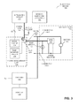
- FIG. 1 presents a block diagram illustrating an electronic device that includes a power-management unit, an integrated circuit and a battery pack in accordance with an embodiment of the present disclosure.
- FIG. 2 presents a block diagram illustrating a power-management unit in the electronic device of FIG. 1 in accordance with an embodiment of the present disclosure.
- FIG. 3 presents a block diagram illustrating operation of the power-management unit of FIG. 2 in accordance with an embodiment of the present disclosure.
- FIG. 4 presents a block diagram illustrating operation of the power-management unit of FIG. 2 in accordance with an embodiment of the present disclosure.
- FIG. 5 presents a timing diagram illustrating operation of the power-management unit of FIG. 2 in accordance with an embodiment of the present disclosure.
- FIG. 6 presents a flowchart illustrating a method for conveying a signal that represents a temperature state of a battery pack and communicating data between an integrated circuit and the battery pack on a signal line in accordance with an embodiment of the present disclosure.
- FIG. 1 presents a block diagram illustrating an electronic device 100 that includes a power-management unit 110 , an integrated circuit 112 (such as a processor, a graphics processor and/or a system-on-chip) and a battery pack 114 .
- Battery pack 114 may include: a battery 116 that provides power to electronic device 100 via connectors 118 ; a battery-monitoring mechanism or BMM 120 (such as control logic and/or firmware, which is sometimes collectively referred to as a ‘gas gauge’) that monitors one or more physical characteristics of battery pack 114 and/or battery 116 (such as a voltage, a current, an internal impedance, a capacity, a charging time, etc.); a temperature sensor 122 (such as a thermistor) that measures a temperature of battery pack 114 and/or battery 116 ; and a signal line 124 , which electrically couples battery-monitoring mechanism 120 and temperature sensor 122 to power-management unit 110 .
- BMM 120 such as control logic and/or
- battery pack 114 is electrically coupled to a remainder of electronic device 100 by three signal lines (instead of four), including those associated with power and ground connectors 118 (which are not shown for clarity) and signal line 124 (which, as described below, combines temperature monitoring and data communication).
- signal line 124 which, as described below, combines temperature monitoring and data communication.
- power management unit 110 may include a single-wire interface (SWI) 126 .
- SWI single-wire interface
- single-wire interface 126 is illustrated by a multiplexer, and integrated circuit 112 implements a single-wire communication protocol, such as HDQ serial data interface (from Texas Instruments, Inc. of Dallas, Tex.), on signal line 128 for use in communicating data with battery-monitoring mechanism 120 . (However, in other embodiments single-wire interface 126 implements the single-wire communication protocol.)
- FIG. 2 presents a block diagram illustrating power-management unit 110 ( FIG. 1 ).
- Power-management unit 110 includes: battery connector 210 electrically coupled to signal line 124 ( FIG. 1 ); an integrated-circuit (IC) connector 212 electrically coupled to integrated circuit 112 via signal line 128 ( FIG. 1 ); an interface circuit 214 that receives a control signal (such as a timing signal) from integrated circuit 112 in FIG. 1 via interface connectors 208 (and, more generally, one or more instructions, commands or signals that are used to control multiplexer 218 ); a temperature-monitoring circuit 216 (or a temperature-monitoring mechanism) that monitors a temperature state of battery pack 114 and/or battery 116 in FIG. 1 ; and multiplexer 218 .
- a control signal such as a timing signal
- a temperature-monitoring circuit 216 or a temperature-monitoring mechanism
- control signal may be received via an I2C bus or interface (from NXP Semiconductors, Inc. of Eindhoven, The Netherlands).
- I2C bus or interface from NXP Semiconductors, Inc. of Eindhoven, The Netherlands.
- a wide variety of communication techniques and protocols can be used to convey the control signal from integrated circuit 112 ( FIG. 1 ) to power-management unit 110 , such as a Serial Peripheral Interface Bus.
- temperature-monitoring circuit 216 may include a current source 220 that drives a current through temperature sensor 122 ( FIG. 1 ) and a buffer or an amplifier 222 (such as an operational amplifier) that outputs the resulting voltage that was on signal line 124 ( FIG. 1 ).
- multiplexer 218 Based on the control signal, multiplexer 218 selectively couples one of: battery connector 210 and integrated-circuit connector 212 , and battery connector 210 and temperature-monitoring circuit 216 .
- signal line 124 FIG. 1
- signal line 124 conveys one of: a signal representing the temperature state, and the communication between integrated circuit 112 ( FIG. 1 ) and battery-monitoring mechanism 120 ( FIG. 1 ).
- power-management unit 110 may facilitate a reduction in the number of connectors and signal lines used to interface with battery pack 114 ( FIG. 1 ).
- the temperature state may indicate whether it is safe to charge battery 116 in battery pack 114 ( FIG. 1 ). Therefore, the temperature state may include an absolute or relative temperature of battery pack 114 and/or battery 116 ( FIG. 1 ), which may be represented by the voltage output by amplifier 222 .
- the resistance may vary between approximately 2 and 50 k ⁇ depending on the temperature of battery pack 114 and/or battery 116 ( FIG. 1 ).
- the voltage output by amplifier 222 may vary between 0.1 and 2.5 V. (Thus, the temperature state may be determined based on an analog signal provided by temperature sensor 122 in FIG.
- temperature-monitoring circuit 216 includes digital logic that converts the signal on signal line 124 ( FIG. 1 ) into a digital value(s) that represents the temperature state.
- the temperature state may include: a thermal condition of battery pack 114 and/or battery 116 ( FIG. 1 ), such as ‘safe to charge’ or ‘unsafe to charge’; and/or a constraint on the charging of battery pack 114 and/or battery 116 ( FIG. 1 ) based on the temperature state (such as a charging current that may not exceed 800, 900 or 1000 mA).
- power-management unit 110 may selectively couple battery pack 114 and temperature-monitoring circuit 216 ( FIG. 2 ) when battery pack 114 is coupled to a charger 130 (which receives power from an adapter 132 that can convert household alternating current (AC) electricity into direct current (DC) electricity for use by electronic device 100 ).
- a return path to charger 130 may be provided via GND in electronic device 100 .
- the selective coupling to the temperature-monitoring circuit 216 FIG.
- the coupling of battery pack 114 and temperature-monitoring circuit 216 may be a default configuration or condition of multiplexer 218 ( FIG. 2 ), and power-management unit 110 may revert to this default condition a time interval (such as 500 ms) after multiplexer 218 ( FIG. 2 ) selectively couples battery pack 114 and integrated circuit 112 . In this way, the temperature state of battery pack 114 and/or battery 116 can be monitored even if the control signal is not provided by integrated circuit 112 .
- signal line 128 coupling integrated circuit 112 and power-management unit 110 may be electrically coupled to a supply voltage (such as 1.8 V) via a pull-up resistor so that signal line 124 is pulled to the supply voltage when multiplexer 218 ( FIG. 2 ) selectively couples integrated circuit 112 and battery pack 114 .
- a supply voltage such as 1.8 V
- signal line 124 can be used to convey a wake signal from battery-monitoring mechanism 120 to transition the host to a normal operating mode (i.e., in embodiments where battery-monitoring mechanism 120 is temporarily a ‘master’ and integrated circuit 112 is temporarily a ‘slave,’ signal line 124 may be used to indicate that a condition has occurred, such as a low battery voltage, where battery-monitoring mechanism 120 wants to wake integrated circuit 112 and make it the master). Because this wake signal can be conveyed when either integrated circuit 112 or temperature-monitoring circuit 216 ( FIG. 2 ) is selectively coupled to battery pack 114 , the wake signal may be detected by a wake circuit in power-management unit 110 and/or by temperature-monitoring circuit 216 ( FIG. 2 ).
- power-management unit 110 may include a wake circuit 224 that detects the wake signal when multiplexer 218 selectively couples integrated circuit 112 ( FIG. 1 ) to battery pack 114 ( FIG. 1 ).
- the wake signal may be a high-to-low conversion on signal line 124 ( FIG. 1 ) while this signal line or bus idles at nominally 1.8 V.
- wake circuit 224 may include a buffer or a logic gate that can detect a digital value representing the wake signal. (Therefore, wake circuit 224 may function as a General Purpose Input/Output pin.) This digital value may be subsequently conveyed to integrated circuit 112 ( FIG. 1 ).
- temperature-monitoring circuit 216 may include a comparator 226 and an AND gate 228 (and, more generally, control logic) to detect the wake signal when the temperature state of battery pack 114 and/or battery 116 ( FIG. 1 ) is being monitored.
- comparator 226 and AND gate 228 may constitute a wake circuit.
- the wake signal from battery-monitoring mechanism 120 may include pulling the voltage on signal line 124 ( FIG. 1 ) below a minimum voltage level associated with temperature sensor 122 in FIG. 1 (such as a voltage below 0.1 V). This low-voltage wake signal may be detected by comparator 226 .
- AND gate 228 may output a digital value indicating that the wake signal is present. This digital value may be conveyed to integrated circuit 112 ( FIG. 1 ).
- FIG. 3 presents a block diagram illustrating operation of power-management unit 110 during a so-called ‘gas-gauge mode,’ in which multiplexer 218 selectively couples signal line 128 to signal line 124 (i.e., integrated circuit 112 communicates data with battery-monitoring mechanism 120 ), as shown by the bold line in FIG. 3 .
- signal line 128 is selectively coupled to signal line 124
- a nominal voltage on signal line 124 may be pulled up to a supply voltage (such as 1.8 V).
- multiplexer 218 may selectively couple temperature-monitoring circuit 216 and signal line 124 based on the control signal. Alternatively, multiplexer 218 may revert to a default condition (and, thus, the temperature-monitoring mode) a time interval after selectively coupling signal line 128 to signal line 124 .
- a time duration of the gas-gauge mode may be 500 ms. More generally, the time duration may be a fraction of a thermal time constant of battery pack 114 and/or battery 116 , so that the temperature state does not change appreciably during the time duration.
- FIG. 4 presents a block diagram illustrating operation of power-management unit 110 during the temperature-monitoring mode.
- temperature-monitoring circuit 216 may periodically monitor the temperature state of battery pack 114 and/or battery 116 , as shown by the bold line in FIG. 4 .
- temperature-monitoring circuit 216 may monitor the temperature state for 200 ⁇ s every 10 ms.
- this duty cycle and monitoring period may be selected based on a thermal time constant of battery pack 114 and/or battery 116 , so that the temperature state does not change appreciably between determinations of the temperature state by temperature-monitoring circuit 216 .
- transitioning from the temperature-monitoring mode to the gas-gauge mode may be initiated by integrated circuit 112 via interface circuit 214 . If the host is in a power-saving or sleep mode, battery-monitoring mechanism 120 may first wake up the host by conveying the wake signal via signal line 124 . After integrated circuit 112 is in the normal operating mode, it may instruct power-management unit 110 (and, thus, multiplexer 218 ) to transition to the gas-gauge mode.
- FIG. 5 presents a timing diagram 500 illustrating operation of power-management unit 110 .
- control signal 512 may facilitate selective coupling by multiplexer 218 of temperature-monitoring circuit 216 and temperature sensor 122 ( FIGS. 1-4 ) for 200 ⁇ s every 10 ms.
- signal 514 on signal line 124 may vary between approximately 0.1 and 2.5 V (depending on the temperature of battery pack 114 and/or battery 116 in FIGS. 1 and 3-4 ).
- control signal 512 may facilitate selective coupling by multiplexer 218 of integrated circuit 112 and battery-monitoring mechanism 120 ( FIGS. 1 and 3-4 ) for approximately 500 ms, so that data 518 can be transferred using a single-wire communication protocol.
- FIG. 6 presents a flowchart illustrating a method 600 for conveying a signal that represents a temperature state of a battery pack (or a battery) and communicating data between an integrated circuit and the battery pack on a signal line, which may be performed by a power-management unit (such as power-management unit 110 in FIG. 1 ).
- a power-management unit such as power-management unit 110 in FIG. 1
- the power-management unit Based on a control signal, the power-management unit selectively couples the signal line to the integrated circuit that communicates with a battery-monitoring mechanism in the battery pack (operation 610 ).
- the power-management unit selectively couples the signal line to a temperature-monitoring circuit that determines the temperature state of the battery pack (operation 612 ).
- method 600 there may be additional or fewer operations. Moreover, the order of the operations may be changed, and/or two or more operations may be combined into a single operation.
- the power management unit 110 may be implemented in hardware to ensure safe and reliable operation even in the face of software and/or component failures. However, in some embodiments at least some of the operations performed in electronic device 100 are implemented in software. Thus, electronic device 100 may include one or more program modules or sets of instructions stored in an optional memory subsystem 134 (such as DRAM or another type of volatile or non-volatile computer-readable memory), which may be executed by a processing subsystem in integrated circuit 112 . (In general, the power-management technique may be implemented more in hardware and less in software, or less in hardware and more in software, as is known in the art.) Note that the one or more computer programs may constitute a computer-program mechanism.
- an optional memory subsystem 134 such as DRAM or another type of volatile or non-volatile computer-readable memory
- instructions in the various modules in optional memory subsystem 134 may be implemented in: a high-level procedural language, an object-oriented programming language, and/or in an assembly or machine language.
- the programming language may be compiled or interpreted, e.g., configurable or configured, to be executed by the processing subsystem.
- Components in electronic device 100 may be coupled by signal lines, links or buses. While electrical communication has been used as an illustrative example, in general these connections may include electrical, optical, or electro-optical communication of signals and/or data. Furthermore, in the preceding embodiments, some components are shown directly connected to one another, while others are shown connected via intermediate components. In each instance the method of interconnection, or ‘coupling,’ establishes some desired communication between two or more circuit nodes, or terminals. Such coupling may often be accomplished using a number of circuit configurations, as will be understood by those of skill in the art; for example, AC coupling and/or DC coupling may be used.
- functionality in these circuits, components and devices may be implemented in one or more: application-specific integrated circuits (ASICs), field-programmable gate arrays (FPGAs), and/or digital signal processors (DSPs).
- ASICs application-specific integrated circuits
- FPGAs field-programmable gate arrays
- DSPs digital signal processors
- the circuits and components may be implemented using bipolar, PMOS and/or NMOS gates or transistors, and signals in these embodiments may include digital signals that have approximately discrete values and/or analog signals that have continuous values.
- components and circuits may be single-ended or differential, and power supplies may be unipolar or bipolar.
- charger 130 may include any combination of hardware and/or software implemented using analog and/or digital circuitry, and may include one or more processors, and volatile and nonvolatile memory.
- charger 130 includes more than one chip or chip set, and in other embodiments charger 130 may operate in conjunction with a system management controller (SMC) in integrated circuit 112 that performs some of the functions of charger 130 .
- SMC system management controller
- the charger and SMC may operate in a master-slave or slave-master configuration.
- battery pack 114 can be any type of battery pack capable of powering electronic device 100 , and can be implemented in any technology. In some embodiments, battery pack 114 includes more than one separate battery and/or battery cell.
- An output of a process for designing an integrated circuit, or a portion of an integrated circuit, comprising one or more of the circuits described herein may be a computer-readable medium such as, for example, a magnetic tape or an optical or magnetic disk.
- the computer-readable medium may be encoded with data structures or other information describing circuitry that may be physically instantiated as an integrated circuit or portion of an integrated circuit.
- data structures are commonly written in: Caltech Intermediate Format (CIF), Calma GDS II Stream Format (GDSII) or Electronic Design Interchange Format (EDIF).
- CIF Caltech Intermediate Format
- GDSII Calma GDS II Stream Format
- EDIF Electronic Design Interchange Format
- Electronic device 100 may include a variety of devices that can include a battery pack, and that can receive electrical current from an adapter and a charger, including: a laptop computer, a media player (such as an MP3 player), an appliance, a subnotebook/netbook, a tablet computer, a smartphone, a cellular telephone, a network appliance, a set-top box, a personal digital assistant (PDA), a toy, a controller, a digital signal processor, a game console, a device controller, a computational engine within an appliance, a consumer-electronic device, a portable computing device or a portable electronic device, a personal organizer, and/or another electronic device.
- a laptop computer such as an MP3 player
- an appliance such as an MP3 player
- subnotebook/netbook such as an MP3 player
- a tablet computer such as an MP3 player
- smartphone such as an MP3 player
- PDA personal digital assistant
- battery 114 may include a protective circuit to prevent battery 116 from being damaged during operation.
- one or more of the components may not be present in electronic device 100 .
- electronic device 100 may include one or more additional components that are not shown in FIG. 1 .
- some or all of a given component can be integrated into one or more of the other components in electronic device 100 and/or positions of components in electronic device 100 can be changed.
Landscapes
- Engineering & Computer Science (AREA)
- Theoretical Computer Science (AREA)
- Chemical & Material Sciences (AREA)
- Health & Medical Sciences (AREA)
- Physics & Mathematics (AREA)
- General Physics & Mathematics (AREA)
- General Chemical & Material Sciences (AREA)
- Electrochemistry (AREA)
- Chemical Kinetics & Catalysis (AREA)
- Manufacturing & Machinery (AREA)
- General Engineering & Computer Science (AREA)
- Life Sciences & Earth Sciences (AREA)
- Immunology (AREA)
- Biomedical Technology (AREA)
- Microelectronics & Electronic Packaging (AREA)
- General Health & Medical Sciences (AREA)
- Medicinal Chemistry (AREA)
- Urology & Nephrology (AREA)
- Molecular Biology (AREA)
- Hematology (AREA)
- Human Computer Interaction (AREA)
- Bioinformatics & Cheminformatics (AREA)
- Pharmacology & Pharmacy (AREA)
- Toxicology (AREA)
- Veterinary Medicine (AREA)
- Tropical Medicine & Parasitology (AREA)
- Biotechnology (AREA)
- Cell Biology (AREA)
- Public Health (AREA)
- Microbiology (AREA)
- Epidemiology (AREA)
- Animal Behavior & Ethology (AREA)
- Food Science & Technology (AREA)
- Analytical Chemistry (AREA)
- Biochemistry (AREA)
- Pathology (AREA)
- Secondary Cells (AREA)
- Charge And Discharge Circuits For Batteries Or The Like (AREA)
Priority Applications (5)
| Application Number | Priority Date | Filing Date | Title |
|---|---|---|---|
| US13/726,503 US9797784B2 (en) | 2012-03-07 | 2012-12-24 | Communication and monitoring of a battery via a single wire |
| CN201380006443.5A CN104067200B (zh) | 2012-03-07 | 2013-03-06 | 经由单线的电池的通信和监测 |
| PCT/US2013/029362 WO2013134379A1 (en) | 2012-03-07 | 2013-03-06 | Communication and monitoring of a battery via a single wire |
| EP13712960.7A EP2776903B1 (en) | 2012-03-07 | 2013-03-06 | Communication and monitoring of a battery via a single wire |
| KR1020147024751A KR101821450B1 (ko) | 2012-03-07 | 2013-03-06 | 단선을 통한 배터리의 모니터링 및 통신 |
Applications Claiming Priority (2)
| Application Number | Priority Date | Filing Date | Title |
|---|---|---|---|
| US201261607911P | 2012-03-07 | 2012-03-07 | |
| US13/726,503 US9797784B2 (en) | 2012-03-07 | 2012-12-24 | Communication and monitoring of a battery via a single wire |
Publications (3)
| Publication Number | Publication Date |
|---|---|
| US20130235902A1 US20130235902A1 (en) | 2013-09-12 |
| US20160223412A9 US20160223412A9 (en) | 2016-08-04 |
| US9797784B2 true US9797784B2 (en) | 2017-10-24 |
Family
ID=49117289
Family Applications (1)
| Application Number | Title | Priority Date | Filing Date |
|---|---|---|---|
| US13/726,503 Active 2034-06-02 US9797784B2 (en) | 2012-03-07 | 2012-12-24 | Communication and monitoring of a battery via a single wire |
Country Status (5)
| Country | Link |
|---|---|
| US (1) | US9797784B2 (zh) |
| EP (1) | EP2776903B1 (zh) |
| KR (1) | KR101821450B1 (zh) |
| CN (1) | CN104067200B (zh) |
| WO (1) | WO2013134379A1 (zh) |
Cited By (2)
| Publication number | Priority date | Publication date | Assignee | Title |
|---|---|---|---|---|
| US20180199416A1 (en) * | 2015-10-14 | 2018-07-12 | The Watt Stopper, Inc. | Methods and apparatus for providing dc power for low voltage lighting |
| US11038363B2 (en) * | 2014-09-30 | 2021-06-15 | Cps Technology Holdings Llc | Battery system to be implemented in an automotive vehicle, wake-up control unit configured to determine whether a short circuit is expected to be present in an electrical system, and short circuit detection unit of an electrical system |
Families Citing this family (7)
| Publication number | Priority date | Publication date | Assignee | Title |
|---|---|---|---|---|
| US9465421B2 (en) * | 2013-03-15 | 2016-10-11 | Broadcom Corporation | Partitioned switch mode power supply (SMPS) interface |
| CN106294238B (zh) * | 2015-05-15 | 2023-09-01 | 杭州纳雄科技有限公司 | 单线供电数据传输电路及传输方法 |
| US10128546B2 (en) * | 2016-06-07 | 2018-11-13 | Ford Global Technologies, Llc | Battery communication system for battery packs |
| KR102202614B1 (ko) | 2017-09-19 | 2021-01-12 | 주식회사 엘지화학 | 배터리 관리 시스템 및 이를 포함하는 배터리 팩 |
| KR102259970B1 (ko) * | 2017-10-13 | 2021-06-02 | 주식회사 엘지에너지솔루션 | 데이터 입력 스케쥴링 장치 |
| KR20190089401A (ko) | 2018-01-22 | 2019-07-31 | 삼성전자주식회사 | 광 신호를 이용하여 배터리 셀을 관리하기 위한 데이터를 송수신하는 배터리 관리 시스템 |
| US10994617B2 (en) | 2018-11-19 | 2021-05-04 | Ford Global Technologies, Llc | Distributed battery thermal runaway detection |
Citations (42)
| Publication number | Priority date | Publication date | Assignee | Title |
|---|---|---|---|---|
| US3534241A (en) * | 1968-09-17 | 1970-10-13 | Texas Instruments Inc | Battery charger |
| US5371453A (en) | 1993-01-28 | 1994-12-06 | Motorola, Inc. | Battery charger system with common charge and data exchange port |
| US5414860A (en) | 1991-01-29 | 1995-05-09 | International Business Machines Incorporated | Power management initialization for a computer operable under a plurality of operating systems |
| EP0661769A2 (en) | 1993-12-31 | 1995-07-05 | Texas Instruments France | Improvements in or relating to battery pack arrangement |
| US5504416A (en) * | 1993-12-15 | 1996-04-02 | Unitrode Corporation | Battery charger circuit including battery temperature control |
| CN1182482A (zh) | 1996-01-26 | 1998-05-20 | 雅马哈发动机株式会社 | 蓄电池的劣化监视方法及其设备 |
| US5912548A (en) | 1996-07-30 | 1999-06-15 | Dallas Semiconductor Corp. | Battery pack monitoring system |
| EP0936719A2 (en) | 1998-02-13 | 1999-08-18 | Sony Corporation | Battery pack and battery system |
| US6005367A (en) | 1998-07-14 | 1999-12-21 | Centurion International, Inc. | Smart power system |
| US6107780A (en) * | 1998-08-25 | 2000-08-22 | Telefonaktiebolaget Lm Ericsson | Method and an arrangement relating to temperature sensing in electric circuitry |
| EP1291999A1 (en) | 2000-04-13 | 2003-03-12 | Makita Corporation | Adapter for battery charger |
| US6549014B1 (en) * | 2002-02-15 | 2003-04-15 | Power Designers, Llc | Battery monitoring method and apparatus |
| US20030117112A1 (en) | 2001-12-24 | 2003-06-26 | Huei-Chiu Chen | Method and apparatus for implementing smart management of a rechargeable battery |
| US20040169489A1 (en) | 2003-02-28 | 2004-09-02 | Raymond Hobbs | Charger, vehicle with charger, and method of charging |
| JP2004311240A (ja) * | 2003-04-08 | 2004-11-04 | Fuji Photo Film Co Ltd | 電源装置 |
| US20050099156A1 (en) | 2003-10-07 | 2005-05-12 | Erich Brenner | Battery determination system for battery-powered devices |
| JP2005131770A (ja) | 2003-10-31 | 2005-05-26 | Matsushita Electric Ind Co Ltd | 電池パック、電動工具及び電動工具システム |
| US20050194935A1 (en) | 2004-02-24 | 2005-09-08 | Atsumasa Kubota | Charging control system and motor-driven tool set |
| US20060139007A1 (en) | 2004-11-29 | 2006-06-29 | Kim Woo C | Apparatus and method for monitoring battery pack |
| US20060226814A1 (en) | 2005-04-08 | 2006-10-12 | Texas Instruments Incorporated | Dual battery pack system interface |
| US20070090788A1 (en) | 2005-10-21 | 2007-04-26 | Hansford Brey D | System and method for recharging a battery exposed to a harsh environment |
| US20070257642A1 (en) | 2003-06-19 | 2007-11-08 | Sean Xiao | Battery cell monitoring and balancing circuit |
| US7317298B1 (en) | 2003-07-01 | 2008-01-08 | American Power Conversion Corporation | Discharging battery monitoring |
| US20080018300A1 (en) * | 2006-07-19 | 2008-01-24 | A123 Systems, Inc. | Method and system for monitoring and balancing cells in battery packs |
| US20080120513A1 (en) | 2006-11-20 | 2008-05-22 | Samsung Electronics Co., Ltd. | Computer and power control method thereof |
| US20090039836A1 (en) | 2007-08-10 | 2009-02-12 | Denso Corporation | Apparatus for controlling power generated by on-vehicle generator on the basis of internal status of on-vehicle battery |
| US20090174370A1 (en) | 2008-01-07 | 2009-07-09 | Oqo, Inc. | Power source sensing and battery charging |
| US20090230923A1 (en) * | 2008-03-14 | 2009-09-17 | Eveready Battery Company, Inc. | Battery management circuit |
| US20090295334A1 (en) * | 2008-06-03 | 2009-12-03 | Jongwoon Yang | Battery pack and charging method for the same |
| US20100085018A1 (en) | 2008-10-07 | 2010-04-08 | Nathan Cruise | Shared control of thermistor and dual purpose thermistor line |
| CN101741403A (zh) | 2008-11-10 | 2010-06-16 | 索尼爱立信移动通信日本株式会社 | 无线通信装置及电源装置 |
| US20100270973A1 (en) * | 2009-04-24 | 2010-10-28 | Panasonic Electric Works Power Tools Co., Ltd. | Battery Pack |
| EP2290781A2 (en) | 2009-08-24 | 2011-03-02 | Panasonic Electric Works Power Tools Co., Ltd. | Charging circuit |
| EP2293781A1 (en) | 2008-04-09 | 2011-03-16 | LEK Pharmaceuticals d.d. | Granulation of active pharmaceutical ingredients |
| US8319479B2 (en) * | 2010-03-23 | 2012-11-27 | Ememory Technology Inc. | Method of estimating battery recharge time and related device |
| US20130038293A1 (en) * | 2007-07-13 | 2013-02-14 | Black & Decker Inc. | Cell Monitoring And Balancing |
| US20130082662A1 (en) * | 2011-09-29 | 2013-04-04 | Texas Instruments, Incorporated | Circuits, devices, methods and systems to secure power-up for battery operating devices even with low current chargers and to execute other performances |
| US8808886B2 (en) * | 2010-10-13 | 2014-08-19 | Samsung Sdi Co., Ltd. | Battery management system and method thereof, and power storage apparatus using the same |
| US8957639B2 (en) * | 2010-12-22 | 2015-02-17 | Atmel Corporation | Event system and timekeeping for battery management and protection system |
| US8961004B2 (en) * | 2010-10-18 | 2015-02-24 | The Johns Hopkins University | Battery phase meter to determine internal temperatures of lithium-ion rechargeable cells under charge and discharge |
| US20160118840A1 (en) * | 2013-05-28 | 2016-04-28 | Kyocera Corporation | Battery pack and portable electronic apparatus |
| US20170141592A1 (en) * | 2015-11-17 | 2017-05-18 | Motorola Solutions, Inc. | Load side method of blocking charger voltage from a battery load |
-
2012
- 2012-12-24 US US13/726,503 patent/US9797784B2/en active Active
-
2013
- 2013-03-06 CN CN201380006443.5A patent/CN104067200B/zh active Active
- 2013-03-06 KR KR1020147024751A patent/KR101821450B1/ko active IP Right Grant
- 2013-03-06 WO PCT/US2013/029362 patent/WO2013134379A1/en active Application Filing
- 2013-03-06 EP EP13712960.7A patent/EP2776903B1/en active Active
Patent Citations (48)
| Publication number | Priority date | Publication date | Assignee | Title |
|---|---|---|---|---|
| US3534241A (en) * | 1968-09-17 | 1970-10-13 | Texas Instruments Inc | Battery charger |
| US5414860A (en) | 1991-01-29 | 1995-05-09 | International Business Machines Incorporated | Power management initialization for a computer operable under a plurality of operating systems |
| US5371453A (en) | 1993-01-28 | 1994-12-06 | Motorola, Inc. | Battery charger system with common charge and data exchange port |
| US5504416A (en) * | 1993-12-15 | 1996-04-02 | Unitrode Corporation | Battery charger circuit including battery temperature control |
| EP0661769A2 (en) | 1993-12-31 | 1995-07-05 | Texas Instruments France | Improvements in or relating to battery pack arrangement |
| CN1182482A (zh) | 1996-01-26 | 1998-05-20 | 雅马哈发动机株式会社 | 蓄电池的劣化监视方法及其设备 |
| US5886527A (en) | 1996-01-26 | 1999-03-23 | Yamaha Hatsudoki Kabushiki Kaisha | Method and device for monitoring deterioration of battery |
| US5912548A (en) | 1996-07-30 | 1999-06-15 | Dallas Semiconductor Corp. | Battery pack monitoring system |
| EP0936719A2 (en) | 1998-02-13 | 1999-08-18 | Sony Corporation | Battery pack and battery system |
| US6005367A (en) | 1998-07-14 | 1999-12-21 | Centurion International, Inc. | Smart power system |
| US6107780A (en) * | 1998-08-25 | 2000-08-22 | Telefonaktiebolaget Lm Ericsson | Method and an arrangement relating to temperature sensing in electric circuitry |
| EP1291999A1 (en) | 2000-04-13 | 2003-03-12 | Makita Corporation | Adapter for battery charger |
| US20030117112A1 (en) | 2001-12-24 | 2003-06-26 | Huei-Chiu Chen | Method and apparatus for implementing smart management of a rechargeable battery |
| US6771042B2 (en) * | 2001-12-24 | 2004-08-03 | Avid Electronics Corp. | Method and apparatus for implementing smart management of a rechargeable battery |
| US6549014B1 (en) * | 2002-02-15 | 2003-04-15 | Power Designers, Llc | Battery monitoring method and apparatus |
| US20040169489A1 (en) | 2003-02-28 | 2004-09-02 | Raymond Hobbs | Charger, vehicle with charger, and method of charging |
| JP2004311240A (ja) * | 2003-04-08 | 2004-11-04 | Fuji Photo Film Co Ltd | 電源装置 |
| US20070257642A1 (en) | 2003-06-19 | 2007-11-08 | Sean Xiao | Battery cell monitoring and balancing circuit |
| US7317298B1 (en) | 2003-07-01 | 2008-01-08 | American Power Conversion Corporation | Discharging battery monitoring |
| US20050099156A1 (en) | 2003-10-07 | 2005-05-12 | Erich Brenner | Battery determination system for battery-powered devices |
| JP2005131770A (ja) | 2003-10-31 | 2005-05-26 | Matsushita Electric Ind Co Ltd | 電池パック、電動工具及び電動工具システム |
| US20050194935A1 (en) | 2004-02-24 | 2005-09-08 | Atsumasa Kubota | Charging control system and motor-driven tool set |
| US20060139007A1 (en) | 2004-11-29 | 2006-06-29 | Kim Woo C | Apparatus and method for monitoring battery pack |
| US20060226814A1 (en) | 2005-04-08 | 2006-10-12 | Texas Instruments Incorporated | Dual battery pack system interface |
| US20070090788A1 (en) | 2005-10-21 | 2007-04-26 | Hansford Brey D | System and method for recharging a battery exposed to a harsh environment |
| CN101529646A (zh) | 2006-07-19 | 2009-09-09 | A123系统公司 | 用于监控和平衡电池组中的电池的方法和系统 |
| US20080018300A1 (en) * | 2006-07-19 | 2008-01-24 | A123 Systems, Inc. | Method and system for monitoring and balancing cells in battery packs |
| US20080120513A1 (en) | 2006-11-20 | 2008-05-22 | Samsung Electronics Co., Ltd. | Computer and power control method thereof |
| CN101295881A (zh) | 2007-04-24 | 2008-10-29 | 凹凸电子(武汉)有限公司 | 电池监控和平衡电路 |
| US20130038293A1 (en) * | 2007-07-13 | 2013-02-14 | Black & Decker Inc. | Cell Monitoring And Balancing |
| US20090039836A1 (en) | 2007-08-10 | 2009-02-12 | Denso Corporation | Apparatus for controlling power generated by on-vehicle generator on the basis of internal status of on-vehicle battery |
| US20090174370A1 (en) | 2008-01-07 | 2009-07-09 | Oqo, Inc. | Power source sensing and battery charging |
| US20090230923A1 (en) * | 2008-03-14 | 2009-09-17 | Eveready Battery Company, Inc. | Battery management circuit |
| EP2293781A1 (en) | 2008-04-09 | 2011-03-16 | LEK Pharmaceuticals d.d. | Granulation of active pharmaceutical ingredients |
| US20090295334A1 (en) * | 2008-06-03 | 2009-12-03 | Jongwoon Yang | Battery pack and charging method for the same |
| US8217628B2 (en) * | 2008-06-03 | 2012-07-10 | Samsung Sdi Co., Ltd. | Battery pack with an automatic current regulation and charging method for the same |
| US20100085018A1 (en) | 2008-10-07 | 2010-04-08 | Nathan Cruise | Shared control of thermistor and dual purpose thermistor line |
| US20120286732A1 (en) * | 2008-10-07 | 2012-11-15 | Black & Decker Inc. | Shared control of thermistor and dual purpose thermistor line |
| CN101741403A (zh) | 2008-11-10 | 2010-06-16 | 索尼爱立信移动通信日本株式会社 | 无线通信装置及电源装置 |
| US20100270973A1 (en) * | 2009-04-24 | 2010-10-28 | Panasonic Electric Works Power Tools Co., Ltd. | Battery Pack |
| EP2290781A2 (en) | 2009-08-24 | 2011-03-02 | Panasonic Electric Works Power Tools Co., Ltd. | Charging circuit |
| US8319479B2 (en) * | 2010-03-23 | 2012-11-27 | Ememory Technology Inc. | Method of estimating battery recharge time and related device |
| US8808886B2 (en) * | 2010-10-13 | 2014-08-19 | Samsung Sdi Co., Ltd. | Battery management system and method thereof, and power storage apparatus using the same |
| US8961004B2 (en) * | 2010-10-18 | 2015-02-24 | The Johns Hopkins University | Battery phase meter to determine internal temperatures of lithium-ion rechargeable cells under charge and discharge |
| US8957639B2 (en) * | 2010-12-22 | 2015-02-17 | Atmel Corporation | Event system and timekeeping for battery management and protection system |
| US20130082662A1 (en) * | 2011-09-29 | 2013-04-04 | Texas Instruments, Incorporated | Circuits, devices, methods and systems to secure power-up for battery operating devices even with low current chargers and to execute other performances |
| US20160118840A1 (en) * | 2013-05-28 | 2016-04-28 | Kyocera Corporation | Battery pack and portable electronic apparatus |
| US20170141592A1 (en) * | 2015-11-17 | 2017-05-18 | Motorola Solutions, Inc. | Load side method of blocking charger voltage from a battery load |
Cited By (5)
| Publication number | Priority date | Publication date | Assignee | Title |
|---|---|---|---|---|
| US11038363B2 (en) * | 2014-09-30 | 2021-06-15 | Cps Technology Holdings Llc | Battery system to be implemented in an automotive vehicle, wake-up control unit configured to determine whether a short circuit is expected to be present in an electrical system, and short circuit detection unit of an electrical system |
| US20180199416A1 (en) * | 2015-10-14 | 2018-07-12 | The Watt Stopper, Inc. | Methods and apparatus for providing dc power for low voltage lighting |
| US10251248B2 (en) * | 2015-10-14 | 2019-04-02 | The Watt Stopper, Inc. | Methods and apparatus for providing DC power for low voltage lighting |
| US20200146131A1 (en) * | 2015-10-14 | 2020-05-07 | The Watt Stopper, Inc. | Methods and apparatus for providing dc power for low voltage lighting |
| US10743395B2 (en) * | 2015-10-14 | 2020-08-11 | The Watt Stopper, Inc. | Methods and apparatus for providing DC power for low voltage lighting |
Also Published As
| Publication number | Publication date |
|---|---|
| EP2776903A1 (en) | 2014-09-17 |
| KR20140124817A (ko) | 2014-10-27 |
| EP2776903B1 (en) | 2017-04-19 |
| US20160223412A9 (en) | 2016-08-04 |
| KR101821450B1 (ko) | 2018-01-23 |
| CN104067200A (zh) | 2014-09-24 |
| US20130235902A1 (en) | 2013-09-12 |
| WO2013134379A1 (en) | 2013-09-12 |
| CN104067200B (zh) | 2016-11-09 |
Similar Documents
| Publication | Publication Date | Title |
|---|---|---|
| US9797784B2 (en) | Communication and monitoring of a battery via a single wire | |
| TWI827581B (zh) | 用於通用序列匯流排功率遞送中的可程式閘極驅動器控制之電路及系統 | |
| CN107038138B (zh) | 通用串行总线功率输送装置和包括其的系统 | |
| US10879686B2 (en) | Overcurrent protection for universal serial bus Type-C (USB-C) connector systems | |
| TWI601381B (zh) | 高清晰度多媒體介面纜線連接裝置與方法 | |
| KR101950910B1 (ko) | 전력 및 데이터의 시간 도메인 다중화 | |
| EP3345282B1 (en) | Usb power delivery dead-battery control | |
| TW201331744A (zh) | Usb集線器和usb集線器的電力供應方法 | |
| US9977475B2 (en) | Over voltage protection for a communication line of a bus | |
| TWI499160B (zh) | Battery status monitoring circuit and battery device | |
| US9599519B2 (en) | Charging a battery based on stored battery characteristics | |
| US7870408B2 (en) | Universal serial bus wakeup circuit | |
| US9235246B2 (en) | Computing device and power supply method of connection module | |
| TW201321960A (zh) | 電子系統的電源功耗控制方法以及相關的電子系統 | |
| TWI527339B (zh) | 充電裝置 | |
| US11768253B1 (en) | Floating ground architectures in USB type-C controllers for fault detection | |
| TWI638261B (zh) | 具有省電功能的電子裝置 |
Legal Events
| Date | Code | Title | Description |
|---|---|---|---|
| AS | Assignment |
Owner name: APPLE INC., CALIFORNIA Free format text: ASSIGNMENT OF ASSIGNORS INTEREST;ASSIGNORS:PATEL, PARIN;MULLINS, SCOTT P.;SIGNING DATES FROM 20121126 TO 20121220;REEL/FRAME:029571/0168 |
|
| STCF | Information on status: patent grant |
Free format text: PATENTED CASE |
|
| MAFP | Maintenance fee payment |
Free format text: PAYMENT OF MAINTENANCE FEE, 4TH YEAR, LARGE ENTITY (ORIGINAL EVENT CODE: M1551); ENTITY STATUS OF PATENT OWNER: LARGE ENTITY Year of fee payment: 4 |