US9796058B2 - Method for producing turbine engine parts, and resulting mould and blank compromising stacked parts - Google Patents
Method for producing turbine engine parts, and resulting mould and blank compromising stacked parts Download PDFInfo
- Publication number
- US9796058B2 US9796058B2 US15/106,132 US201415106132A US9796058B2 US 9796058 B2 US9796058 B2 US 9796058B2 US 201415106132 A US201415106132 A US 201415106132A US 9796058 B2 US9796058 B2 US 9796058B2
- Authority
- US
- United States
- Prior art keywords
- blank
- faces
- opposite
- parts
- mould
- Prior art date
- Legal status (The legal status is an assumption and is not a legal conclusion. Google has not performed a legal analysis and makes no representation as to the accuracy of the status listed.)
- Active
Links
Images


Classifications
-
- B—PERFORMING OPERATIONS; TRANSPORTING
- B23—MACHINE TOOLS; METAL-WORKING NOT OTHERWISE PROVIDED FOR
- B23P—METAL-WORKING NOT OTHERWISE PROVIDED FOR; COMBINED OPERATIONS; UNIVERSAL MACHINE TOOLS
- B23P15/00—Making specific metal objects by operations not covered by a single other subclass or a group in this subclass
- B23P15/02—Making specific metal objects by operations not covered by a single other subclass or a group in this subclass turbine or like blades from one piece
-
- B—PERFORMING OPERATIONS; TRANSPORTING
- B22—CASTING; POWDER METALLURGY
- B22D—CASTING OF METALS; CASTING OF OTHER SUBSTANCES BY THE SAME PROCESSES OR DEVICES
- B22D13/00—Centrifugal casting; Casting by using centrifugal force
Definitions
- the present invention relates to a method for producing metal parts for a turbine engine, and more particularly wheel blades for a turbine of a turbojet or a turboprop engine of an aircraft.
- Some cylindrical blanks may have different micro-structures as regards their respective centres and their periphery. This may result in different micro-structures within the same blade.
- some other blanks are obtained by lost-wax foundry using a ceramic mould, wherein the metal alloy is cast. Developing such single-use mould is difficult. Additionally, interactions between the molten metal and the ceramics may result in casting defects on the surfaces of the blanks, and lost-wax may cause geometrical defects in the blanks, if quality is bad.
- the present invention makes it possible to remedy at least a part of the above-mentioned drawbacks, in a simple, efficient and economical way.
- the solution provided here consists in the blank obtained by casting being a solid polyhedron with two generally trapezoidal opposing sides, with the parts being machined in the blank.
- “Trapezoid” as used herein is understood to refer to a quadrilateral with two parallel sides that have different lengths.
- the mould used it is recommended that it comprises at least one polyhedral mould cavity having two opposing sides, each having a general trapezoidal shape, adapted to the moulding of said solid blank.
- the mould will preferably be rotating, for the simultaneous moulding of several blanks by centrifugation.
- the mould will then be connected to means providing rotation about a central rotation axis and will comprise several mould cavities radially extending about said central axis.
- Such technology makes it possible to produce TiAL blanks, more particularly for turbine engine blades.
- the method which the mould is intended for can be applied to the moulding of blades, i.e. parts each having a longitudinal axis, and along such axis, a root at one end, a heel at a second end, and a curved section vane which extends there between.
- each blank approaches the integration of at least a part of the constraints applied to filling, hardening, stripping, cutting of the blanks and machining of the parts, so that the latter comply with the expected characteristics:
- the blank must be adapted to totally contain at least two identical blades, positioned side by side, slightly distant from each other and stacked,
- said blades must then be machined in the blank, so that one is rotated by 180° relative to the adjacent blade, about the longitudinal axis which then passes through two of the lateral sides of the block, which are, among the lateral sides, preferably those which are perpendicular to the sides having a general trapezoidal shape (within a clearance angle ⁇ 1 hereunder).
- the mould will preferably have an angular opening of the trapezoidal base ranging from 2° to 10°, preferably from 3° to 8°, xN, with N being the number of blades to be machined in the blank.
- the mould which is, for instance a permanent mould wherein the alloy is cast, will preferably be made of metal, which shall make it possible to limit the contamination of the blank material by that of the mould.
- the substantially trapezoidal base of the blank is placed on two opposing sides having larger surface areas of the blank, and
- the considered blank has an angular opening of the trapezoidal base ranging from 2° to 10°, preferably from 3° to 8°, xN, with N being the number of blades to be machined in the blank and/or:
- the considered blank has a general trapezoid-based prism shape, and/or:
- the considered blank has a general oblique prism shape, and/or:
- the prism has an opening angle preferably ranging from 0° to 30°, and preferably from 0° to 20°.
- FIGS. 3 to 5 have precise dimensions and comply with industrial reality, like dimensioned drawings, wherein:
- FIG. 1 schematically shows a device for manufacturing blanks or bars by moulding
- FIG. 2 is a schematic view in perspective of a first embodiment of a moulded blank, obtained, for instance, using the moulding device of FIG. 1 ,
- FIGS. 3, 4, 5 are views of an alternative moulded blank of FIG. 2 , from a first side, from above (IV arrow), and from a second side (V arrow), respectively
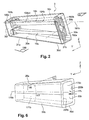
- FIG. 6 schematically shows a part of the mould, with its cavity for moulding the blank of FIG. 2 .
- FIG. 7 shows the VII-VII section of FIG. 6 , for a blank according to the FIGS. 3 to 5 .
- FIG. 1 thus shows a device 1 for producing blanks or bars 3 , while executing successive melting, casting and moulding operations.
- the device 1 comprises a closed sealed enclosure 5 whereto a partial vacuum is applied.
- a TiAl-based metal alloy ingot 7 for example, is fixed at one end of an electrode 9 which is connected to a terminal of a power source, the other terminal of which is connected to a crucible 11 accommodated in the enclosure 5 .
- VSM Vacuum Skull Melting When melting of the ingot is completed in the crucible, the metal alloy is poured into a preferably metallic and permanent mould 13 .
- Such mould 13 makes it possible to cast the alloy by centrifugation.
- the mould is rotated about an axis A using an engine 15 .
- the mould comprises several recesses or cavities, such as 17 a , 17 b here, which radially extend about the axis A.
- the alloy to be cast is brought to the centre of the mould and the rotation of the mould distributes it into the cavities. It is recommended for the cavities to be regularly spaced about such axis.
- the axis A will preferably be vertical and the axis (such as 170 a , 170 b here) in each cavity will be horizontal.
- the mould cavities, such as 17 a , 17 b are not shown with the optimized shape(s) thereof, particularly to suit the moulding of a blank 3 complying with that of FIGS. 2 to 5 .
- the mould 13 is disassembled and the cast parts are extracted.
- the shape of the cavities 17 a , 17 b . . . will of course match that of the parts. The following information regarding the parts or the blanks will thus also apply to the cavities in the mould.
- FIG. 2 shows the general shape of a moulded blank complying with the solution provided here, and which may be one of those bearing reference 3 above, that the bar or blank 3 is a solid polyhedron with two generally trapezoidal opposing sides 30 a , 30 b.
- the blank 3 has a general trapezoid-based prism shape. It is considered that a prism is a polyhedron with two equal and parallel bases, here 30 a and 30 b , and the other so-called lateral faces of which are parallelograms.
- two opposing sides such as the base sides 30 a and 30 b , are not parallel by less than 5° of angle (more particularly because of a clearance angle, such as al hereunder) and/or not equal as regards the surface by less than 5%.
- the blank 3 is an hexahedron.
- the prism is a right prism. It may be oblique; refer to FIG. 5 .
- the prism configuration has been optimized in FIGS. 3-5 ; It always has a general trapezoidal shape, and is oblique.
- the parts such as 19 a , 19 b are slightly distant from each other and stacked.
- the blank 3 is thus higher (vertical direction Z; FIGS. 2, 6 ) than thick or wide (direction Y perpendicular to Z)
- each one (for example the one bearing reference 19 b ) shall thus have a longitudinal axis 191 b and, along this axis, a root 193 b adjacent to an internal platform 195 b , at a first end, a heel (or external platform) 192 b at a second end, and a curved section vane 194 b which extends between the platforms.
- the longitudinal axis 191 b may cross the geometrical centre of the root and of the heel.
- the vanes (such as 194 b ; FIG. 2 ) of the blades will additionally be, each, advantageously provided to be machined, with the convex face thereof (such as 194 b in FIG. 2 ) being oriented towards the face 30 c , with the opposing concave face then being oriented towards the face 30 d , and vice versa for the vane 19 a , closest to side 30 d.
- the heels (or external platforms) 192 a , 192 b are provided to be machined facing, and close to the side 30 e , whereas the internal platforms, such as 193 b , shall be close to the opposing side 30 f.
- FIG. 2 as well as in FIGS. 3-5 :
- the two (preferably strictly mutually parallel), lateral sides 30 e , 30 f are thus perpendicular to the two opposing (globally trapezoidal) sides of the base having larger surface areas 30 a , 30 b (within the clearance angle .alpha. 1 ),
- an angular opening ⁇ 2 of the trapezoidal base should be provided, (angle between the sides, 30 c , 30 d ) ranging from 2° to 10°, (and preferably from 3° to 8°, xN, with N being the number of blades to be machined in the blank.
- the latter shall preferably have an oblique prism shape, with an opening angle ⁇ 3 ranging from 0° to 30°, and preferably from 0° to 20°, as in the case of FIGS. 3 and 5 . If not null, this angle ⁇ 3 is thus the angle at which the prism changes from right to oblique.
- such a conformation of the/each blank will enable, relative to the faces surrounding same, the machining of all the (identical) parts at a minimum depth, as regards the constraints imparted by the shape of such parts and the structural characteristics thereof.
- a shell mould will preferably be used.
- mould cavities specifically if this concerns that of FIG. 1 , such as for example the one bearing reference 17 b , the following is recommended, as illustrated in FIG. 6 where, for simplification purposes, the blank to be moulded is supposed to be that of FIG. 2 :
- the/each mould cavity such as 17 b
- the/each mould cavity is a polyhedron and has two opposing sides 171 b , 173 b of a generally trapezoidal shape adapted to the moulding of said solid blank,
- the trapezoidal base (face 171 b or 173 b ) then has an angular opening ⁇ 2 ranging from 2° to 10°, preferably from 3° to 8°, xN, with N being, as mentioned above, the number of blades to be machined in the blank, i.e. side by side along faces 30 e , 30 f , which will then be all the longer (refer to length L 1 FIG. 3 of the faces 30 c , 30 d , for the side 300 since many parts are substantially aligned along same.
- the opening giving access to the (each) cavity here bearing reference 23 b , is positioned on the trimmed lateral side of such cavity, trimmed opposing sides 231 b , 233 b of which are the larger bases of the opposing sides 171 b , 173 b of a generally trapezoidal shape,
- the mould enclosure consists (at least) of two shells 25 a , 25 b , with each one integrating a part of the concerned mould cavity, here 17 b.
- the face 30 e of the blank will be moulded at the location of, or opposite the opening 23 b and the metal alloy will enter the cavity through the opening 23 b (refer to the arrow of FIG. 6 ), and the moulded, hardened blank 3 could leave it there; a simpler stripping of the blank will however be possible if separable shells 25 a , 25 b are used.
- the bottom of the cavity (and thus of the mould) is solid, opposite the opening 23 b.
- the concerned mould cavity such as 17 b
- the concerned mould cavity will then have a general trapezoid-based prism shape 171 b , 173 b with an opening angle ⁇ 3 of the prism ranging from 0° to 30°, and preferably from 0° to 20°.
- each blank may have a length L 2 , between the sides 30 e , 30 f ranging from 160 to 240 cm, and a length L 3 between the sides 30 a , 30 b ranging from 40 to 70 cm.
- the length L 1 may range from 100 to 140 cm.
Abstract
- a) casting a metal alloy in a mould in order to produce a blank (3); and
- b) machining the blank in order to produce the parts,
characterized in that the blank obtained by casting is a solid polyhedron with two generally trapezoidal opposing sides (30 a, 30 b), and the parts are machined in the blank.
Description
Claims (8)
Applications Claiming Priority (3)
| Application Number | Priority Date | Filing Date | Title |
|---|---|---|---|
| FR1363346A FR3015326B1 (en) | 2013-12-20 | 2013-12-20 | PROCESS FOR MANUFACTURING TURBOMACHINE PIECES, DRAFT WITH SUPERIORED PIECES AND MOLD OBTAINED |
| FR1363346 | 2013-12-20 | ||
| PCT/FR2014/053327 WO2015092239A1 (en) | 2013-12-20 | 2014-12-12 | Method for producing turbine engine parts, and resulting mould and blank comprising stacked parts |
Publications (2)
| Publication Number | Publication Date |
|---|---|
| US20160318137A1 US20160318137A1 (en) | 2016-11-03 |
| US9796058B2 true US9796058B2 (en) | 2017-10-24 |
Family
ID=50290032
Family Applications (1)
| Application Number | Title | Priority Date | Filing Date |
|---|---|---|---|
| US15/106,132 Active US9796058B2 (en) | 2013-12-20 | 2014-12-12 | Method for producing turbine engine parts, and resulting mould and blank compromising stacked parts |
Country Status (4)
| Country | Link |
|---|---|
| US (1) | US9796058B2 (en) |
| EP (1) | EP3083134B1 (en) |
| FR (1) | FR3015326B1 (en) |
| WO (1) | WO2015092239A1 (en) |
Families Citing this family (2)
| Publication number | Priority date | Publication date | Assignee | Title |
|---|---|---|---|---|
| WO2014057208A2 (en) * | 2012-10-09 | 2014-04-17 | Snecma | Method for manufacturing metal parts for a turbine machine |
| DE102021000614A1 (en) | 2021-02-08 | 2022-08-11 | Access E.V. | Mold for the crack-free production of a metal object with at least one undercut, in particular from intermetallic alloys such as TiAl, FeAl and other brittle or crack-prone materials, as well as a corresponding method. |
Citations (9)
| Publication number | Priority date | Publication date | Assignee | Title |
|---|---|---|---|---|
| GB2290998A (en) | 1994-07-06 | 1996-01-17 | Inco Engineered Prod Ltd | Manufacture of forged components involving centrifugal casting |
| US20020014006A1 (en) * | 2000-07-20 | 2002-02-07 | Hans-Egon Brock | Process and blank for preparing rhomboidal blades for axial turbo engines |
| JP2006336059A (en) | 2005-05-31 | 2006-12-14 | Toshiba Corp | Heat-resistant steel member and manufacturing method therefor |
| WO2008125129A1 (en) | 2007-04-11 | 2008-10-23 | Manfred Renkel | Method for production of precision castings by centrifugal casting |
| EP2067546A1 (en) | 2007-11-27 | 2009-06-10 | General Electric Company | Systems for centrifugally casting highly reactive titanium metals |
| EP2223755A1 (en) | 2009-02-04 | 2010-09-01 | Rolls-Royce plc | Casting method |
| DE102010042585A1 (en) * | 2010-10-18 | 2012-04-19 | Siemens Aktiengesellschaft | Production of blades of a turbomachine from cold-formed base material |
| WO2014072661A1 (en) * | 2012-11-09 | 2014-05-15 | Mecachrome France | Method and device for manufacturing turbine blades |
| US9221096B2 (en) * | 2013-03-11 | 2015-12-29 | Ati Properties, Inc. | Centrifugal casting apparatus and method |
-
2013
- 2013-12-20 FR FR1363346A patent/FR3015326B1/en active Active
-
2014
- 2014-12-12 US US15/106,132 patent/US9796058B2/en active Active
- 2014-12-12 EP EP14827832.8A patent/EP3083134B1/en active Active
- 2014-12-12 WO PCT/FR2014/053327 patent/WO2015092239A1/en active Application Filing
Patent Citations (11)
| Publication number | Priority date | Publication date | Assignee | Title |
|---|---|---|---|---|
| GB2290998A (en) | 1994-07-06 | 1996-01-17 | Inco Engineered Prod Ltd | Manufacture of forged components involving centrifugal casting |
| US5671533A (en) * | 1994-07-06 | 1997-09-30 | Doncaster Plc | Manufacture of forged components |
| US20020014006A1 (en) * | 2000-07-20 | 2002-02-07 | Hans-Egon Brock | Process and blank for preparing rhomboidal blades for axial turbo engines |
| JP2006336059A (en) | 2005-05-31 | 2006-12-14 | Toshiba Corp | Heat-resistant steel member and manufacturing method therefor |
| WO2008125129A1 (en) | 2007-04-11 | 2008-10-23 | Manfred Renkel | Method for production of precision castings by centrifugal casting |
| EP2067546A1 (en) | 2007-11-27 | 2009-06-10 | General Electric Company | Systems for centrifugally casting highly reactive titanium metals |
| EP2223755A1 (en) | 2009-02-04 | 2010-09-01 | Rolls-Royce plc | Casting method |
| DE102010042585A1 (en) * | 2010-10-18 | 2012-04-19 | Siemens Aktiengesellschaft | Production of blades of a turbomachine from cold-formed base material |
| WO2014072661A1 (en) * | 2012-11-09 | 2014-05-15 | Mecachrome France | Method and device for manufacturing turbine blades |
| US20150292339A1 (en) * | 2012-11-09 | 2015-10-15 | Mecachrome France | Method and Device for Manufacturing Turbine Blades |
| US9221096B2 (en) * | 2013-03-11 | 2015-12-29 | Ati Properties, Inc. | Centrifugal casting apparatus and method |
Also Published As
| Publication number | Publication date |
|---|---|
| FR3015326A1 (en) | 2015-06-26 |
| WO2015092239A1 (en) | 2015-06-25 |
| FR3015326B1 (en) | 2016-01-01 |
| EP3083134A1 (en) | 2016-10-26 |
| EP3083134B1 (en) | 2018-10-31 |
| US20160318137A1 (en) | 2016-11-03 |
Similar Documents
| Publication | Publication Date | Title |
|---|---|---|
| US7669637B2 (en) | Impeller for supercharger and method of manufacturing the same | |
| RU2421296C2 (en) | Method of producing gas turbine engine part including cooling air release opening | |
| US20150075746A1 (en) | Method of Casting a Component Having Interior Passageways | |
| JP2014208373A (en) | Casting-in/cooling structure for turbine airfoil | |
| US20070163744A1 (en) | Cylinder block casting bulkhead window formation | |
| US20170333979A1 (en) | Method for manufacturing a compressor impeller | |
| US9796058B2 (en) | Method for producing turbine engine parts, and resulting mould and blank compromising stacked parts | |
| JP6355839B2 (en) | Die casting system with ceramic mold for forming components usable in gas turbine engines | |
| EP3002070B1 (en) | Casting of engine parts | |
| US9844843B2 (en) | Method for producing turbine engine parts, and resulting blank and mould | |
| JP5243157B2 (en) | Manufacturing method of casting for tire mold | |
| US9969035B2 (en) | Method for producing a turbine engine part, and resulting mould and intermediate blank | |
| BR112019017551A2 (en) | electrotechnical coil, method for producing the same, and electromagnetic or electrical machine comprising at least one such coil | |
| EP2354464B1 (en) | Cast shroud slots with pre-swirled leakage | |
| JP4092674B2 (en) | Molding method of wax model with ceramic core | |
| GB2090181A (en) | Manufacturing a Blade or Vane for a Gas Turbine Engine | |
| JPH071075A (en) | Investment casting method | |
| JPH084873B2 (en) | Mold for producing mold and method for producing mold using the mold | |
| US10682687B2 (en) | Turbomachine blade cooling circuit | |
| JP2022533097A (en) | Molds for manufacturing components by metal injection and epitaxial growth, and associated manufacturing methods | |
| CN108788009A (en) | Component for manufacturing turbine engine blade | |
| Molchanyuk | An experience of the'POLYGON' computer simulation system of casting process | |
| JPH06106320A (en) | Die for centrifugal casting of ti or ti alloy casting |
Legal Events
| Date | Code | Title | Description |
|---|---|---|---|
| AS | Assignment |
Owner name: SNECMA, FRANCE Free format text: ASSIGNMENT OF ASSIGNORS INTEREST;ASSIGNORS:HUCHIN, PATRICK EMILIEN PAUL EMILE;DESCHANDOL, KARINE;DIGARD BROU DE CUISSART, SEBASTIEN;AND OTHERS;SIGNING DATES FROM 20131220 TO 20150216;REEL/FRAME:038947/0651 |
|
| STCF | Information on status: patent grant |
Free format text: PATENTED CASE |
|
| AS | Assignment |
Owner name: SAFRAN AIRCRAFT ENGINES, FRANCE Free format text: CHANGE OF NAME;ASSIGNOR:SNECMA;REEL/FRAME:046479/0807 Effective date: 20160803 |
|
| AS | Assignment |
Owner name: SAFRAN AIRCRAFT ENGINES, FRANCE Free format text: CORRECTIVE ASSIGNMENT TO CORRECT THE COVER SHEET TO REMOVE APPLICATION NOS. 10250419, 10786507, 10786409, 12416418, 12531115, 12996294, 12094637 12416422 PREVIOUSLY RECORDED ON REEL 046479 FRAME 0807. ASSIGNOR(S) HEREBY CONFIRMS THE CHANGE OF NAME;ASSIGNOR:SNECMA;REEL/FRAME:046939/0336 Effective date: 20160803 |
|
| MAFP | Maintenance fee payment |
Free format text: PAYMENT OF MAINTENANCE FEE, 4TH YEAR, LARGE ENTITY (ORIGINAL EVENT CODE: M1551); ENTITY STATUS OF PATENT OWNER: LARGE ENTITY Year of fee payment: 4 |