US9795451B2 - Surgical monitoring system and related methods for spinal instrument angular relation - Google Patents
Surgical monitoring system and related methods for spinal instrument angular relation Download PDFInfo
- Publication number
- US9795451B2 US9795451B2 US14/841,270 US201514841270A US9795451B2 US 9795451 B2 US9795451 B2 US 9795451B2 US 201514841270 A US201514841270 A US 201514841270A US 9795451 B2 US9795451 B2 US 9795451B2
- Authority
- US
- United States
- Prior art keywords
- angle
- target
- instrument
- pedicle
- relationship
- Prior art date
- Legal status (The legal status is an assumption and is not a legal conclusion. Google has not performed a legal analysis and makes no representation as to the accuracy of the status listed.)
- Active
Links
Images


Classifications
-
- A61B19/5244—
-
- A—HUMAN NECESSITIES
- A61—MEDICAL OR VETERINARY SCIENCE; HYGIENE
- A61B—DIAGNOSIS; SURGERY; IDENTIFICATION
- A61B34/00—Computer-aided surgery; Manipulators or robots specially adapted for use in surgery
- A61B34/10—Computer-aided planning, simulation or modelling of surgical operations
-
- A—HUMAN NECESSITIES
- A61—MEDICAL OR VETERINARY SCIENCE; HYGIENE
- A61B—DIAGNOSIS; SURGERY; IDENTIFICATION
- A61B17/00—Surgical instruments, devices or methods
- A61B17/16—Instruments for performing osteoclasis; Drills or chisels for bones; Trepans
- A61B17/17—Guides or aligning means for drills, mills, pins or wires
- A61B17/1703—Guides or aligning means for drills, mills, pins or wires using imaging means, e.g. by X-rays
-
- A—HUMAN NECESSITIES
- A61—MEDICAL OR VETERINARY SCIENCE; HYGIENE
- A61B—DIAGNOSIS; SURGERY; IDENTIFICATION
- A61B34/00—Computer-aided surgery; Manipulators or robots specially adapted for use in surgery
- A61B34/20—Surgical navigation systems; Devices for tracking or guiding surgical instruments, e.g. for frameless stereotaxis
-
- A—HUMAN NECESSITIES
- A61—MEDICAL OR VETERINARY SCIENCE; HYGIENE
- A61B—DIAGNOSIS; SURGERY; IDENTIFICATION
- A61B5/00—Measuring for diagnostic purposes; Identification of persons
- A61B5/24—Detecting, measuring or recording bioelectric or biomagnetic signals of the body or parts thereof
- A61B5/316—Modalities, i.e. specific diagnostic methods
- A61B5/388—Nerve conduction study, e.g. detecting action potential of peripheral nerves
-
- A—HUMAN NECESSITIES
- A61—MEDICAL OR VETERINARY SCIENCE; HYGIENE
- A61B—DIAGNOSIS; SURGERY; IDENTIFICATION
- A61B6/00—Apparatus or devices for radiation diagnosis; Apparatus or devices for radiation diagnosis combined with radiation therapy equipment
- A61B6/12—Arrangements for detecting or locating foreign bodies
-
- A—HUMAN NECESSITIES
- A61—MEDICAL OR VETERINARY SCIENCE; HYGIENE
- A61B—DIAGNOSIS; SURGERY; IDENTIFICATION
- A61B6/00—Apparatus or devices for radiation diagnosis; Apparatus or devices for radiation diagnosis combined with radiation therapy equipment
- A61B6/46—Arrangements for interfacing with the operator or the patient
- A61B6/461—Displaying means of special interest
-
- A—HUMAN NECESSITIES
- A61—MEDICAL OR VETERINARY SCIENCE; HYGIENE
- A61B—DIAGNOSIS; SURGERY; IDENTIFICATION
- A61B6/00—Apparatus or devices for radiation diagnosis; Apparatus or devices for radiation diagnosis combined with radiation therapy equipment
- A61B6/54—Control of apparatus or devices for radiation diagnosis
- A61B6/547—Control of apparatus or devices for radiation diagnosis involving tracking of position of the device or parts of the device
-
- A—HUMAN NECESSITIES
- A61—MEDICAL OR VETERINARY SCIENCE; HYGIENE
- A61F—FILTERS IMPLANTABLE INTO BLOOD VESSELS; PROSTHESES; DEVICES PROVIDING PATENCY TO, OR PREVENTING COLLAPSING OF, TUBULAR STRUCTURES OF THE BODY, e.g. STENTS; ORTHOPAEDIC, NURSING OR CONTRACEPTIVE DEVICES; FOMENTATION; TREATMENT OR PROTECTION OF EYES OR EARS; BANDAGES, DRESSINGS OR ABSORBENT PADS; FIRST-AID KITS
- A61F2/00—Filters implantable into blood vessels; Prostheses, i.e. artificial substitutes or replacements for parts of the body; Appliances for connecting them with the body; Devices providing patency to, or preventing collapsing of, tubular structures of the body, e.g. stents
- A61F2/02—Prostheses implantable into the body
- A61F2/30—Joints
- A61F2/46—Special tools for implanting artificial joints
- A61F2/4657—Measuring instruments used for implanting artificial joints
-
- A—HUMAN NECESSITIES
- A61—MEDICAL OR VETERINARY SCIENCE; HYGIENE
- A61B—DIAGNOSIS; SURGERY; IDENTIFICATION
- A61B34/00—Computer-aided surgery; Manipulators or robots specially adapted for use in surgery
- A61B34/20—Surgical navigation systems; Devices for tracking or guiding surgical instruments, e.g. for frameless stereotaxis
- A61B2034/2046—Tracking techniques
-
- A—HUMAN NECESSITIES
- A61—MEDICAL OR VETERINARY SCIENCE; HYGIENE
- A61B—DIAGNOSIS; SURGERY; IDENTIFICATION
- A61B90/00—Instruments, implements or accessories specially adapted for surgery or diagnosis and not covered by any of the groups A61B1/00 - A61B50/00, e.g. for luxation treatment or for protecting wound edges
- A61B90/06—Measuring instruments not otherwise provided for
- A61B2090/067—Measuring instruments not otherwise provided for for measuring angles
-
- A61B5/04001—
-
- A—HUMAN NECESSITIES
- A61—MEDICAL OR VETERINARY SCIENCE; HYGIENE
- A61B—DIAGNOSIS; SURGERY; IDENTIFICATION
- A61B6/00—Apparatus or devices for radiation diagnosis; Apparatus or devices for radiation diagnosis combined with radiation therapy equipment
- A61B6/44—Constructional features of apparatus for radiation diagnosis
- A61B6/4429—Constructional features of apparatus for radiation diagnosis related to the mounting of source units and detector units
- A61B6/4435—Constructional features of apparatus for radiation diagnosis related to the mounting of source units and detector units the source unit and the detector unit being coupled by a rigid structure
- A61B6/4441—Constructional features of apparatus for radiation diagnosis related to the mounting of source units and detector units the source unit and the detector unit being coupled by a rigid structure the rigid structure being a C-arm or U-arm
-
- A—HUMAN NECESSITIES
- A61—MEDICAL OR VETERINARY SCIENCE; HYGIENE
- A61B—DIAGNOSIS; SURGERY; IDENTIFICATION
- A61B90/00—Instruments, implements or accessories specially adapted for surgery or diagnosis and not covered by any of the groups A61B1/00 - A61B50/00, e.g. for luxation treatment or for protecting wound edges
- A61B90/36—Image-producing devices or illumination devices not otherwise provided for
- A61B90/37—Surgical systems with images on a monitor during operation
-
- A—HUMAN NECESSITIES
- A61—MEDICAL OR VETERINARY SCIENCE; HYGIENE
- A61F—FILTERS IMPLANTABLE INTO BLOOD VESSELS; PROSTHESES; DEVICES PROVIDING PATENCY TO, OR PREVENTING COLLAPSING OF, TUBULAR STRUCTURES OF THE BODY, e.g. STENTS; ORTHOPAEDIC, NURSING OR CONTRACEPTIVE DEVICES; FOMENTATION; TREATMENT OR PROTECTION OF EYES OR EARS; BANDAGES, DRESSINGS OR ABSORBENT PADS; FIRST-AID KITS
- A61F2/00—Filters implantable into blood vessels; Prostheses, i.e. artificial substitutes or replacements for parts of the body; Appliances for connecting them with the body; Devices providing patency to, or preventing collapsing of, tubular structures of the body, e.g. stents
- A61F2/02—Prostheses implantable into the body
- A61F2/30—Joints
- A61F2/46—Special tools for implanting artificial joints
- A61F2/4657—Measuring instruments used for implanting artificial joints
- A61F2002/4668—Measuring instruments used for implanting artificial joints for measuring angles
-
- A—HUMAN NECESSITIES
- A61—MEDICAL OR VETERINARY SCIENCE; HYGIENE
- A61N—ELECTROTHERAPY; MAGNETOTHERAPY; RADIATION THERAPY; ULTRASOUND THERAPY
- A61N1/00—Electrotherapy; Circuits therefor
- A61N1/02—Details
- A61N1/04—Electrodes
- A61N1/05—Electrodes for implantation or insertion into the body, e.g. heart electrode
- A61N1/0551—Spinal or peripheral nerve electrodes
Definitions
- the present invention relates generally to determining a desired trajectory and/or monitoring the trajectory of surgical instruments and implants and, more particularly, doing so during spinal surgery, including but not limited to ensuring proper placement of pedicle screws during pedicle fixation procedures and ensuring proper trajectory during the establishment of an operative corridor to a spinal target site.
- Pedicle fixation which is frequently performed during spinal fusions and other procedures designed to stabilize or support one or more spine segments.
- Pedicle fixation entails securing bone anchors (e.g. pedicle screws) through the pedicles and into the vertebral bodies of the vertebrae to be fixed or stabilized.
- Rods or other connectors are used to link adjacent pedicle screws and thus fix or stabilize the vertebrae relative to each other.
- a major challenge facing the surgeon during pedicle fixation is implanting the pedicle screws without breaching, cracking, or otherwise compromising the pedicle wall, which may easily occur if the screw is not properly aligned with the pedicle axis. If the pedicle (or more specifically, the cortex of the medial wall, lateral wall, superior wall and/or inferior wall) is breached, cracked, or otherwise compromised, the patient may experience pain and/or neurologic deficit due to unwanted contact between the pedicle screw and delicate neural structures, such as the spinal cord or exiting nerve roots, which lie in close proximity to the pedicle. A misplaced pedicle screw often necessitates revision surgery, which is disadvantageously painful for the patient and costly, both in terms of recovery time and hospitalization.
- the present invention is aimed primarily at eliminating or at least reducing the challenge associated with determining the optimal or desired trajectory for surgical instruments and/or implants and monitoring the trajectory of surgical instruments and/or implants during surgery.
- the present invention facilitates the safe and reproducible use of surgical instruments and/or implants by providing the ability to determine the optimal or desired trajectory for surgical instruments and/or implants and monitor the trajectory of surgical instruments and/or implants during surgery.
- the present invention may be used to ensure safe and reproducible pedicle screw placement by monitoring the axial trajectory of surgical instruments used during pilot hole formation and/or screw insertion. Neurophysiologic monitoring may also be carried out during pilot hole formation and/or screw insertion.
- the present invention is suitable for use in any number of additional surgical procedures where the angular orientation or trajectory of instrumentation and/or implants and/or instrumentation is important, including but not limited to general (non-spine) orthopedics and non-pedicular based spine procedures.
- surgical instruments are generally described below as pedicle access tools, cannulas, retractor assemblies, and imaging systems (e.g. C-arms), various other surgical instruments (e.g. drills, screw drivers, taps, etc. . . . ) may be substituted depending on the surgical procedure being performed and/or the needs of the surgeon.
- a surgical trajectory system may include an angle-measuring device (hereafter “tilt sensor”) and a feedback device.
- tilt sensor measures its angular orientation with respect to a reference axis (such as, for example, “vertical” or “gravity”) and the feedback device may display or otherwise communicate the measurements. Because the tilt sensor is attached to a surgical instrument the angular orientation of the instrument, may be determined as well, enabling the surgeon to position and maintain the instrument along a desired trajectory during use.
- the tilt sensor may include a sensor package enclosed within a housing.
- the housing is coupled to or formed as part of a universal clip to attach the tilt sensor to a surgical instrument.
- the sensor package may comprise a 2-axis accelerometer which measures its angular orientation in each of a sagittal and transverse plane with respect to the acting direction of gravity.
- the sagittal orientation corresponds to a cranial-caudal angle and the transverse orientation corresponds to a medial-lateral angle.
- the sensor package is preferably situated such that when the tilt sensor is perpendicular to the direction of gravity, the inclinometer registers a zero angle in both the sagittal and transverse planes.
- the angular orientation of the longitudinal axis of the instrument is determined relative to gravity.
- a 3-axis sensor may be used.
- the 3-axis sensor may comprise a 2-axis accelerometer to measure sagittal and transverse orientation and either a gyroscope and/or one or more magnetometers (e.g. a single 3-axis magnetometer or a combination of a 1-axis magnetometer and a 2-axis magnetometer) to measure the longitudinal axial rotation of the instrument.
- a surgical instrument for use with the surgical trajectory system may comprise, by way of example only, a pedicle access probe.
- the instrument may generally comprise a probe member having a longitudinal axis and a handle.
- the probe member may be embodied in any variety of configurations that can be inserted through an operating corridor to a pedicle target site and bore, pierce, or otherwise dislodge and/or impact bone to form a pilot hole for pedicle screw placement.
- the probe member may be composed of any material suitable for surgical use and strong enough to impact bone to form a pilot hole. In one embodiment, the material may be capable of conducting an electric current signal to allow for the use of neurophysiologic monitoring.
- the handle may be permanently or removably attached to the probe member and may be shaped and dimensioned in any of a number of suitable variations to assist in manipulating the probe member.
- the handle includes a cutout region for accommodating attachment of the universal clip.
- the handle includes an integral cavity for receiving the tilt sensor directly.
- the tilt sensor is permanently integrated into the instrument handle.
- a control unit may be communicatively linked to the tilt sensor via a hard wire or wireless technology.
- the feedback device may communicate any of numerical, graphical, and audio feedback corresponding to the orientation of the tilt sensor in the sagittal plane (cranial-caudal angle) and in the transverse plane (medial-lateral angle).
- the surgical instrument In general, to orient and maintain the surgical instrument along a desired trajectory during pilot hole formation, the surgical instrument is advanced to the pedicle (through any of open, mini-open, or percutaneous access) while oriented in the zero-angle position. The instrument is then angulated in the sagittal plane until the proper cranial-caudal angle is reached. Maintaining the proper cranial-caudal angle, the surgical instrument may then be angulated in the transverse plane until the proper medial-lateral angle is attained. Once the control unit or secondary feedback device indicates that both the medial-lateral and cranial caudal angles are matched correctly, the instrument may be advanced into the pedicle to form the pilot hole, monitoring the angular trajectory of the instrument until the hole formation is complete.
- the desired angular trajectory (e.g. the cranial-caudal angle and the medial-lateral angle) must first be determined.
- Preoperative superior view MRI or CAT scan images are used to determine the medial-lateral angle.
- a reference line is drawn through the center of the vertebral body and a trajectory line is then drawn from a central position in the pedicle to an anterior point of the vertebral body. The resulting angle between the trajectory line and the reference line is the desired medial-lateral angle to be used in forming the pilot hole.
- the cranial-caudal angle may be determined using an intraoperative lateral fluoroscopy image incorporating a vertical reference line. Again, a trajectory line is drawn from the pedicle nucleus to an anterior point of the vertebral body. The resulting angle between the trajectory line and the vertical reference line is the desired cranial-caudal angle to be used in forming the pilot hole.
- a protractor outfitted with a tilt sensor may be provided to assist in determining the cranial-caudal angle in the operating room.
- the cranial-caudal angle may be calculated preoperatively using imaging techniques that provide a lateral view of the spine.
- the medial-lateral and cranial-caudal angles should be determined for each pedicle that is to receive a pedicle screw. Alternate and/or additional methods for predetermining the pedicle angles are also contemplated and may be used without deviating from the scope of the present invention.
- a reticle may be provided to attach the tilt sensor to a standard C-arm.
- the reticle comprises an integrated sensor and a mount which may attach to the C-arm.
- the reticle further comprises an adjustable laser.
- the laser may be aimed along the C-arm axis. In use the laser cross-hair will mark a target incision site on a patient when the C-arm is oriented in line with the pedicle axis.
- Radiopaque markers are also integrated into the reticle. The markers provide a reference for properly aligning the fluoroscopic images.
- the C-arm may be placed in the trajectory lateral position. From the trajectory lateral position the C-arm may be rotated back to the A/P position while maintaining the radial rotation imparted to achieve the trajectory lateral position.
- a surgical instrument may be advanced to the target site and positioned on the lateral margin of the pedicle, the preferred starting point according to this example. The depth of penetration of the surgical instrument may be checked during advancement by rotating the C-arm back to a trajectory lateral view.
- the starting point may be determined using an “owls eye” view.
- the C-arm may be oriented such that it is aligned with both the medial-lateral and cranial-caudal angles as discussed above.
- the tip of the pedicle access instrument is placed on the skin so that the tip is located in the center of the pedicle of interest on the fluoroscopic image; and thereafter the instrument is advanced to the pedicle. Another fluoroscopic image is taken to verify that the tip of the instrument is still aligned in the center of the pedicle.
- a standard surgical instrument may be guided along a pedicle axis without the use of an additional tilt sensor on the surgical instrument.
- a surgical instrument properly aligned with the pedicle axis will appear as a black dot.
- the surgical instrument may be advanced through the pedicle while ensuring that it continues to appear as only a dot on the fluoroscopy image. The depth of penetration may again be checked with a trajectory lateral image.
- Neurophysiologic monitoring may be carried out in conjunction with the trajectory monitoring performed by the surgical trajectory system.
- the surgical trajectory system may be used in combination with neurophysiologic monitoring systems to conduct pedicle integrity assessments before, during, and after pilot hole formation, as well as to detect the proximity of nerves while advancing and withdrawing the surgical instrument from the pedicle target site.
- a neurophysiology system is described which may be used in conjunction with the surgical trajectory system.
- the neurophysiology system and the surgical trajectory system may be integrated into a single system.
- Neurophysiology monitoring and trajectory monitoring may be carried out concurrently and the control unit may display results for each of the trajectory monitoring function and any of a variety of neurophysiology monitoring functions, including, but not necessarily limited to, Twitch Test, Free-run EMG, Basic Screw Test, Difference Screw Test, Dynamic Screw Test, Nerve Detection, Nerve Health, MEP, and SSEP.
- the neurophysiology system includes a display, a control unit, a patient module, one or more of an EMG harness and an SSEP harness, a host of surgical accessories (including an electric coupling device) capable of being coupled to the patient module via one or more accessory cables.
- the electric coupling device may be the tilt sensor clip.
- the surgical instrument is configured to transmit a stimulation signal from the neurophysiology system to the target body tissue (e.g. the pedicle).
- the surgical instrument probe members may be formed of material capable of conducting the electric signal.
- the probe members may be insulated, with an electrode region near the distal end of the probe member for delivering the electric signal and a coupling region near the proximal end of the probe member for coupling to the neurophysiology system.
- a pedicle screw may be implanted in a target pedicle according to the following steps. First, preoperative measurements corresponding to the medial/lateral angle of the pedicle are determined using suitable imaging technology, such as for example, MRI. Level the C-arm and then attach the laser reticle to the C-arm using the integrated tilt sensor and LED indicators to align the laser reticle into proper position and the adjustable clamps to lock the reticle in place. Adjust the laser cross-hairs if necessary such that the center of the cross-hairs align with the calibrated center of the C-arm emitter. Select from the navigated guidance system whether fluoroscopy will be used and indicate which side of the body the C-arm is positioned.
- suitable imaging technology such as for example, MRI.
- FIG. 1 is an exemplary view of a surgical trajectory system, including a sensor clip, C-arm, laser reticle, surgical instrument and control unit, according to one embodiment of the present invention
- FIG. 2 is a perspective view of a tilt sensor clip of the surgical trajectory system of FIG. 1 , according to one embodiment of the present invention
- FIG. 3 is a perspective view of a tilt sensor, the outer housing shown in dashed lines to make visible the sensor situated within the housing, according to one embodiment of the present invention
- FIG. 4 is a perspective view depicting the bottom of the tilt sensor, according to one embodiment of the present invention.
- FIG. 5 is a close up view of a handle portion of a surgical instrument, according to one embodiment of the present invention.
- FIGS. 6-7 illustrate a sensor clip connector used to attach the tilt sensor to a surgical instrument, according to one embodiment of the present invention
- FIG. 8 is an illustration of an operating theater equipped with a surgical table, C-arm fluoroscope, fluoroscope monitor, practitioner, and patient;
- FIG. 9 is a front view of the C-arm of FIG. 8 oriented in an A/P position for generating an A/P fluoroscopic image
- FIG. 10 is front view of the C-arm of FIG. 8 oriented in a lateral position for generating a lateral fluoroscopic image
- FIGS. 11A-11B are front views of the C-arm of FIG. 8 oriented according to desired medial-lateral angles between the A/P position of FIG. 9 and the lateral position of FIG. 10 ;
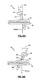
- FIGS. 12A-12B are side views of the C-arm of FIG. 8 oriented according to various cranial-caudal angles;
- FIGS. 13-19 are exemplary views of a laser reticle equipped with an integrated tilt sensor, radiopaque cross-hairs, and laser light, according to one embodiment of the present invention.
- FIG. 20 is a top view of a vertebral body showing the medial-lateral angle A 1 of the pedicle axis;
- FIG. 21 is a side view of a vertebral body showing the cranial-caudal angle A 2 of the pedicle axis;
- FIG. 22 illustrates a superior view preoperative MRI image used to determine the proper medial-lateral angle for hole formation, according to one embodiment of the present invention
- FIG. 23 illustrates an intraoperative lateral fluoroscopy image used to determine the proper cranial-caudal angle for hole formation, according to one embodiment of the present invention
- FIG. 24 is an exemplary screen display of the surgical trajectory system 10 incorporating both alpha-numeric and graphical indicia, according to one embodiment of the present invention.
- FIG. 25 is an exemplary screen display of the surgical trajectory system 10 incorporating both alpha-numeric and graphical indicia, according to another embodiment of the present invention.
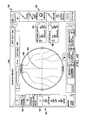
- FIGS. 26-36 are exemplary screen displays of the surgical trajectory system 10 incorporating alpha-numeric, graphical indicia, and fluoroscopic image data, and various control features according to another embodiment of the present invention.
- FIGS. 37-46 are exemplary screen displays of the surgical trajectory system 10 incorporating alpha-numeric, graphical indicia, and fluoroscopic image data, and various control features according to yet another embodiment of the present invention.
- FIG. 47 is a perspective view of an exemplary neuromonitoring system for use in conjunction with the surgical trajectory system of FIG. 1 , according to on3 embodiment of the present invention.
- the present invention may facilitate safe and reproducible pedicle screw placement by monitoring the axial trajectory of various surgical instruments used during pilot hole formation and/or screw insertion.
- intraoperative imaging performance may be improved and radiation exposure minimized by monitoring the precise orientation of the imaging device.
- monitoring the orientation of surgical access instruments can aid in both the insertion and positioning of the access instruments themselves, as well as, aiding in the later insertion of instruments and/or implants through the surgical access instruments.
- the present invention may be suitable for use in any number of additional surgical actions where the angular orientation or trajectory of instrumentation and/or implants is important.
- the present invention may be useful in directing, among other things, the formation of tunnels for ligament or tendon repair and the placement of facet screws.
- the surgical trajectory system is generally discussed herein as being attached to instruments such as pedicle access tools, C-arms, dilating cannulas, and tissue retractors, other instruments (e.g. drills, screw drivers, taps, inserters, etc. . . .
- the trajectory monitoring system may be used in conjunction with, or integrated into, a neurophysiology system for assessing one or more of pedicle integrity and nerve proximity, among others functions, as will be described below.
- pilot hole formation is meant to encompass any of, or any combination of, creating a hole in bone (such as, for example only, by awling, boring, drilling, etc. . . . ) and preparing a previously formed hole (such as, for example only, by tapping the hole).
- a surgical trajectory system 10 including a tilt sensor clip 12 (also referred to as “tilt sensor”) engaged with a surgical instrument 14 , a feedback and control device comprising a control unit 16 , and a laser reticle 18 coupled to a C-arm 20 .
- the tilt sensor clip 12 measures its own angular orientation with respect to a reference axis, such as vertical or gravity.
- the control unit 16 provides feedback related to the angle measurements obtained by the tilt sensor clip 12 for reference by a practitioner and receives user input.
- the tilt sensor clip 12 attaches to surgical instrument 14 in a known positional relationship such that the angular orientation of the instrument 14 may be determined with respect to the same reference axis.
- surgical instrument 14 may be aligned and advanced along a pre-determined pedicle axis, thereby decreasing the risk of breaching the pedicle wall.
- Tilt sensor 12 illustrated in FIGS. 2-4 , includes a sensor package 22 ( FIG. 3 ) enclosed within a housing 24 .
- the housing 24 may be made from a surgical grade plastic, metal, or any material suitable for use in the surgical field. Housing 24 is configured to snugly couple with the surgical instrument 14 in a known positional relationship, as will be described below.
- sensor package 22 comprises a 2-axis accelerometer that measures angular orientation with respect to the acting direction of gravity.
- the angular orientation of tilt sensor 12 is measured in a sagittal plane and a transverse plane.
- the orientation of the tilt sensor 12 in the transverse plane represents a medial-lateral angle A 1 ( i ) with respect to a patient and the direction of gravity.
- Orientation in the sagittal plane represents a cranial-caudal angle A 2 ( i ) with respect to the direction of gravity and the patient.
- Sensor package 22 is preferably situated within housing 24 such that when housing 24 is perpendicular to the direction of gravity, the accelerometer registers zero angle in both the sagittal and transverse planes (i.e.
- both the cranial-caudal angle and medial-lateral angle are equal to zero.
- tilt sensor 12 when tilt sensor 12 is fixed perpendicular to the longitudinal axis of the surgical instrument 14 , the angular orientation of the instruments longitudinal axis may be determined relative to gravity.
- the accuracy of the tilt sensor 12 may be affected by movement around the third, rotational axis.
- measurements should preferably be taken only when at least one of the longitudinal axis 26 and transverse axis 28 tilt sensor 12 are aligned with a selected reference frame, such as for example, the longitudinal axis of the patient's spine (i.e. the tilt sensor 12 should be in approximately the same rotational alignment for each measurement). In one embodiment, this may be accomplished effectively using visual aids to help keep the tilt sensor 12 in line with the reference frame and/or ensure measurements may be taken when the tilt sensor 12 appears to be in this correct rotational position.
- the sensor clip 12 attaches to the instrument 14 such that a free end of the clip may “point” to the patients feet when the sensor 12 is in the correct rotational position.
- the surgical instrument 14 is inadvertently or purposely rotated during use, the practitioner need only continue, or reverse rotation until the tilt sensor 12 again appears to be perpendicular to the long axis of the spine.
- various markings or other indicia may be included on one or more of the tilt sensor 12 and the surgical instrument 14 to ensure proper alignment prior to obtaining measurements.
- the sensor package 22 may be configured such that it may account for, or at least measure, rotation (e.g. a “3-axis sensor”).
- the sensor package 22 includes a 2-axis accelerometer augmented by a gyroscope (not shown), which may comprise any number of commercially available gyroscopes. While the accelerometer again measures the angular orientation of the tilt sensor 12 with respect to gravity, the gyroscope detects movement about the rotational or z-axis. By monitoring the rate of rotation and time, the system 10 may determine the degrees of rotation imparted on the surgical instrument 14 (and tilt sensor 12 ).
- the control unit 16 may indicate to the user that the sensor 12 is not aligned in the correct reference frame such that the user may take steps to correct the alignment prior to taking measurements.
- the control unit 16 may display feedback according to any number of suitable methods.
- the feedback may utilize numeric indicia to indicate the degree of misalignment, color indicia, such as red or green indicating the rotational status (e.g. aligned or misaligned), audible alert tones (e.g. low frequency tones for non-alignment and high frequency tones for proper alignment or visa versa or any combination thereof), etc. . . . .
- the system 10 may be configured to correct the angle data output based on the degree of rotation detected. In this manner, angle data from the tilt sensor 12 may be acquired from any rotational position.
- a button (not shown) may be provided on the tilt sensor 12 and/or control unit 16 to initially zero the sensor package 22 when it is aligned with the reference frame.
- the sensor package 22 accounts for rotational movement by utilizing magnetometers (not shown) in conjunction with the 2-axis accelerometers, where the magnetometer may comprise any number of commercially available magnetometers.
- the sensor package 22 includes a triplet of magnetic sensors oriented perpendicular to each other, one pointing in the x-axis, one in the y-axis, and third pointing in the z-axis.
- the magnetic sensors in the x and y axis act as a compass and calculate a heading of tilt sensor 12 relative to magnetic north.
- the third magnetometer in the z-axis and the x and y axis accelerometers monitor the tilt permitting the “compass” to work when it is not level to the ground.
- the system 10 may calculate the amount of axial rotation relative to an established reference frame (i.e. the patient).
- the control unit 16 may again be configured to indicate the rotational status of the tilt sensor 12 to the user, allowing them to realign the sensor 22 with the proper reference frame prior to establishing a reading.
- the feedback device 16 may again utilize numeric indicia to indicate the degree of misalignment, color indicia, such as red or green indicating the rotational status (e.g. aligned or misaligned), audible alert tones (e.g. low frequency and/or volume tones for non-alignment and high frequency and/or volume tones for proper alignment or visa versa or any combination thereof), etc. . . .
- Surgical instrument 14 may comprise a pedicle access probe.
- instrument 14 may be any of the insulated pedicle access probes described in detail in the commonly owned and co-pending U.S. patent application Ser. No. 11/448,237, entitled “Insulated Pedicle Access System and Related Methods,” and filed on Jun. 6, 2006, the entire contents of which is incorporated by reference as if set forth herein in its entirety.
- Instrument 14 comprises generally a probe member 30 , having a longitudinal axis 32 , and a handle 34 .
- Probe member 30 may be embodied in any variety of configurations that can be inserted through an operating corridor to a pedicle target site and bore, pierce, or otherwise dislodge and/or impact bone to form a pilot hole for pedicle screw placement.
- Probe member 30 may be generally cylindrical in shape, however, probe member 30 may be provided in any suitable shape having any suitable cross-section (e.g. generally oval, polygonal, etc. . . . ).
- a distal region 36 of probe member 30 may have a shaped tip 38 formed of any number of shapes generally suited to effect pilot hole formation, such as, by way of example only, a beveled point, double diamond, drill bit, tap, and a generally tapered awl.
- a proximal region 40 of probe member 30 may be configured to couple the housing 24 of sensor clip 12 .
- Probe member 30 may be composed of any material suitable for surgical use and strong enough to impact bone to form a pilot hole. In one embodiment, the material may also be capable of conducting an electric current signal to allow for the use of neurophysiologic monitoring.
- probe member 30 may be composed of titanium, stainless steel, or other surgical grade alloy.
- the distal region 36 may also be equipped with a retractable insulation sheath 44 . The sheath 44 ensures maximum efficiency of an electrical stimulation signal that may be delivered to the shaped tip 38 during neurophysiologic monitoring that may be conducted in conjunction with the surgical trajectory monitoring of system 10 , as described below.
- Handle 34 may be permanently or removably attached to probe member 30 along the proximal region 40 .
- Handle 34 may be shaped and dimensioned in any of a number of suitable variations to assist in manipulating probe member 30 .
- the handle 34 may be generally T-shaped such as the handle pictured in FIG. 4 .
- Other suitable shapes for handle 34 may include, but are not necessarily limited to, generally spherical, ellipsoidal, and egg-shaped.
- Sensor clip 12 forms a sturdy connection with probe member 30 such that the tilt sensor 12 is maintained in a position perpendicular to the longitudinal axis 32 of probe member 30 .
- the tilt sensor 12 When the longitudinal axis 32 of probe member 30 is parallel to the direction of gravity, the tilt sensor 12 is perpendicular to the direction of gravity (i.e. the zero-angle position). In other words, when the longitudinal axis 32 of probe member 30 is parallel to the acting direction of gravity, both the cranial-caudal angle and the medial-lateral angle will be zero-degrees.
- housing 24 includes a fastener end 46 dimensioned to snugly receive at least a portion of instrument 14 .
- fastener end 46 comprises an end hook 48 , and a handle receiver 50 .
- the end hook 48 is configured to snap on and tightly grasp the proximal region 40 , as illustrated in FIG. 4 .
- the end hook 48 is fitted onto the proximal end 40 of the instrument 14 . Thereafter the housing 24 is rotated until the handle receiver 50 fully engages with the handle 34 of the instrument 14 ( FIGS. 6-7 ).
- FIG. 6 illustrates, by way of example only, a the proximal end 40 (shown in cross-section) tightly positioned within the end hook 48 and before engaging the handle 34 (also shown in cross-section) in the handle receiver 50 .
- FIG. 7 illustrates the handle 34 (again in cross-section) after the clip 12 has been rotated into position with the handle 34 fully engaged in the handle receiver 50 .
- fastener end 46 is dimensioned to prevent the unintentional disengagement of instrument 14 from the sensor clip 12 .
- sensor clip 12 When engaged, sensor clip 12 extends perpendicular to the longitudinal axis 32 of instrument 14 . To release the surgical instrument 14 , the clip 12 may be rotated to disengage the handle receiver 50 from the handle 34 , and the end hook 48 may be released.
- secondary feedback system 52 comprises a collection of LED light indicators to provide an indication of the angular orientation of surgical instrument 14 relative to a reference orientation.
- the collection of LED's includes four LED directional lights 54 - 60 , a central LED light 62 , and a function LED light 64 .
- the four LED directional lights 54 - 60 are independently operated to provide an indication to the user of the sensors 12 (and hence, the instrument 14 ) angular position relative to a desired position (as determined, for example, by predetermined angle measurements captured by or inputted into the system 10 ).
- two opposing LED lights 54 and 56 may correspond to the orientation of the sensor 12 in the cranial-caudal direction and the other two opposing LED lights 58 and 60 may correspond to the orientation in the medial-lateral directions.
- the LED directional lights 54 - 60 will light to indicate the direction in which the instrument 14 needs to be adjusted to align with the desired trajectory.
- the control unit 16 is communicatively linked to tilt sensor clip 12 and functions to provide feedback to the surgeon regarding the angle of the tilt sensor 12 and instrument 14 relative to the desired angles (e.g. predetermined medial-lateral and cranial-caudal angles) as well as receive user input related to various aspects of the trajectory system 10 .
- the control unit 16 includes a display 66 which may show one or more or alpha-numeric, graphic, and color indicia indicative of the sensor 12 trajectory, imported fluoroscopic or other images, patient and or user information, and other system related information.
- the control unit 16 may also receive user input, such as by way of example, user selectable parameters and/or preferences, procedure related data (including but not necessarily limited to predetermined medial-lateral angles, predetermined cranial-caudal angles), etc. . . . .
- the control unit 16 display 66 may include tools which may be utilized by the user, such as by way of example only, a virtual protractor for predetermining angles.
- the control unit 16 may be configured to utilize audio indicators as well.
- control unit 16 may utilize a code based on the emission of audio tones to indicate the angular orientation of the tilt sensor 12 relative to predetermined reference angles corresponding to the desired trajectory.
- One method for implementing an audio code involves varying one or more of the volume, pitch, frequency, pulse rate, and length of the audio tone based on the determined orientation of the sensor 12 relative to the predetermined orientation ranges. Audio feedback may be used alone, or in combination with one or both of the alpha-numeric, graphic, and color indicia previously described.
- a first audible signal may be indicative of an optimal variance between the trajectory of the instrument and at least one of the first and second determined angular relationships between the sensor 12 and the reference direction.
- a second audible signal may be indicative of an unacceptable variance between the trajectory of the instrument and at least one of the first and second determined angular relationships between the sensor 12 and the reference direction.
- a third audible signal may be indicative of an acceptable yet not optimal variance between the trajectory of the instrument and at least one of the first and second determined angular relationships between the sensor 12 and the reference direction.
- the communication link between the sensor clip 12 and may be accomplished via hard-wire (e.g. data cable 68 of FIG. 1 ) and/or via wireless technology, in which case the tilt sensor 12 and control unit 16 may include additional hardware commonly used for enabling such wireless communication. If communicatively linked to the feedback device 16 via hard-wire, the position of the feedback device 16 should be such that the tilt sensor 12 may move freely without tensioning the data cable 68 .
- the laser reticle 18 is attached to C-arm 20 (fluoroscope) to aid in orienting the C-arm 20 into an advantageous position.
- C-arm 20 fluoroscope
- the reticle 18 is equipped with an integrated sensor package 70 .
- Sensor package 70 comprises an accelerometer similar to the sensor package 22 of clip 12 (such that a repeat discussion is not necessary).
- Including a tilt sensor package 70 in the reticle allows the system 10 to determine the angular position of the reticle 18 , and hence the C-arm 20 to which it is attached, with respect to gravity.
- the C-arm 20 and laser reticle 18 will now be discussed in more detail.
- FIG. 8 there is shown a typical operating theatre in which a practitioner 72 may perform surgical procedures on a patient 74 .
- the patient 74 is positioned on a radiolucent operating table 76 .
- Arrayed around the table 76 are a standard C-arm 20 , comprising a frame 78 , a signal transmitter 80 , and a signal receiver/image intensifier 82 , and the control unit 16 which receives and displays video feed from the C-arm 20 , allowing live fluoroscopic images to be integrated with the trajectory monitoring system 10 .
- an x-ray beam 84 having a central axis 86 , may be directed from the signal transmitter 80 through a desired area of patient 74 and picked up by the signal receiver 82 .
- An image of the patient's 74 body tissue located in the path of beam 84 may be generated and displayed on the display 66 .
- the C-arm 20 is discussed herein generally for use during spine surgery to capture images of the spine, such discussion is for exemplary purposes only. It will be understood that the C-arm 20 and laser reticle 18 combination may be utilized for imaging in a wide variety of surgical procedures.
- the C-arm frame 78 may be adjusted to alter the path of the beam 84 , and thus the image that is generated.
- the frame 78 is oriented such that beam 84 travels parallel to the direction of gravity. With the patient in the prone position, as shown herein, this position of frame 78 generates an anterior-posterior (A/P) image.
- This position of C-arm 20 is referred to hereafter as the A/P position.
- Rotating the frame 90° in a medial-lateral direction (through a transverse plane), as depicted in FIG. 10 directs the beam 84 perpendicular to the direction of gravity and generates a lateral image.
- This position of the C-arm 20 is referred to as the lateral position.
- A/P and lateral images may both be useful during a spinal procedure and the C-arm may be adjusted between the A/P and lateral positions numerous times during the procedure.
- the frame 78 may also be oriented in any position within the transverse plane between the A/P and lateral positions, such that the beam 84 forms an angle A 1 ( c ) (the medial-lateral angle) between zero and 90° with respect the direction of gravity. Furthermore, as illustrated in FIGS.
- the frame 78 may also be rotated in a cranial-caudal direction (within a sagittal plane) such that the beam 84 forms another angle A 2 ( c ) (the cranial-caudal angle) with respect to the direction of gravity.
- the C-arm 20 may be oriented such that one or both of angles A 1 ( c ) and A 2 ( c ) correspond to the desired axis of trajectory of a pedicle bone, i.e. angles A 1 and A 2 (owl's eye or oblique view), as will be discussed in more detail below.
- the angular orientation of the C-arm with respect to the reference axis may be determined.
- This enables the practitioner to quickly position the C-arm 20 in a known orientation, such as, by way of example only, the precise orientation in which a previous image was acquired. Doing so may eliminate the time and extra radiation exposure which is often endured while acquiring numerous images while “hunting” for the right image.
- Attaching the sensor 70 (via reticle 18 ) to the C-arm may further enable the practitioner to determine the angular orientation of anatomical structures within the patient (e.g. vertebral pedicles), as will be described below. This may be advantageous, for example only, when the practitioner is performing pedicle fixation and preoperative images (such as the MRI or CAT images which may be used to determine the pedicle axis angle A 1 ) are not available for preoperative planning, as described above.
- laser reticle 18 may be attached to the receiver 82 of the C-arm 20 , as pictured in FIG. 1 .
- FIG. 13 illustrates one embodiment of laser reticle 18 comprising a reticle frame 1152 , radiopaque cross hair marker 1154 , radiolucent front cover 1158 , radiolucent back plate 1159 , adjustable clamps 1160 , sensor tilt LED indicators 1164 , and an adjustable laser emitter system 96 .
- FIG. 14 illustrates an exploded view of laser reticle 18 .
- the reticle 18 is configured to generate a reference cross-hair viewable in fluoroscopic images generated by C-arm 20 .
- FIG. 13 illustrates one embodiment of laser reticle 18 comprising a reticle frame 86 , radiopaque cross hair marker 88 , radiolucent front cover 90 , radiolucent back plate 91 , adjustable clamps 92 , sensor tilt LED indicators 94 , and an adjustable laser emitter system 96 .
- FIG. 14 illustrates an exploded view of laser reticle 18 .
- Reticle frame 86 may be made of aluminum material in a generally circular configuration with an inner window opening 98 .
- Window opening 98 is to allow a fluoroscopic image to pass through window 98 unobstructed by the metal material of frame 86 .
- reticle frames may include, but are not necessarily limited to, a generally rectangular configuration with square window opening. With reference to FIGS. 13-14 , reticle frame 86 has a front, leading edge 100 and a back edge 102 .
- FIG. 15 illustrates, by way of example only, one embodiment of radiopaque cross hair marker 88 .
- radiopaque cross hair 88 When attached to the receiver 82 of the C-arm 20 , radiopaque cross hair 88 is captured in the fluoroscopic image, giving the operator a reference point to the center of the receiver 82 .
- the cross-hairs 88 provide vertical reference line in the fluoroscopic image, as discussed below.
- the radiopaque cross hair marker 88 may be produced from metal BB's 106 fixed onto the radiolucent back plate 91 .
- the cross-hair pattern may comprise a single radiopaque BB 106 as the exact center, with four lines of BB's extending out from the center, along the vertical and horizontal axis of reticle 18 .
- Radiopaque cross hair marker 88 may also comprise a longer, vertical arrow which points to gravity when the reticle is properly mounted and the C-arm is in the lateral position.
- the radiopaque marker 88 is described as being formed by metal BB's fixed in a cross-hair pattern onto a radiolucent case, it can be appreciated that other suitable materials and configurations may be used to produce the same radiopaque target effect.
- Laser reticle 18 is preferably mounted to the C-arm 82 with the C-arm in the lateral position, which allows gravity to help correctly position the laser reticle 18 and the corresponding radiopaque cross-hair marker 88 .
- Laser reticle 18 includes a set of adjustable clamps 92 , a sensor package ( 70 ), and sensor tilt LED indicators 94 to assist in the positioning of laser reticle 18 on to C-arm 82 .
- a sensor package 70 similar to sensor package 22 is integrated within the housing of the laser reticle 18 .
- the sensor package 70 is preferably situated such that it is orthogonal to the reference markers 88 , and when the tilt sensor 70 is perpendicular to the direction of gravity, the sensor registers a zero angle in both the sagittal and transverse planes.
- the sensor package is communicatively linked to sensor tilt LED indicators 94 , located near the superior edge of the laser reticle 18 , and the center LED indicator will light up when the tilt sensor is perpendicular to the direction of gravity. If the tilt sensor is not perpendicular to the direction of gravity, the sensor tilt LED indicators 94 will prompt the operator to tilt the laser reticle 18 in the direction of the lit LED indicator until the center LED indicator lights up, indicating that the sensor package 70 is perpendicular to the direction of gravity.
- Laser reticle 18 may be shaped in a generally circular pattern to correspond to the circular shape of the receiver 82 .
- laser reticle 18 may be shaped and dimensioned in any of a number of suitable variations including, but not necessarily limited to, generally rectangular, triangular, ellipsoidal, and polygonal.
- Laser reticle 18 also includes an adjustable laser cross hair emitter, which may generate a cross-haired target onto the patient's skin at the surgical access site. Adjustment knobs may be used to adjust the laser emitter along the sagittal and transverse planes. The laser is generated from the center of the laser reticle 18 , and when looking down the axis protruding from the center of the reticle 18 the point of laser generation directly overlaps the center point of the radiopaque cross hair 88 .
- An advantage of providing an adjustable laser emitter is to allow the operator to point the laser down any desirable path (and thus correct for deformities in the C-arm frame that occur over time).
- the operator may adjust the laser emitter so that it propagates directly towards the center of the C-arm signal transmitter 80 and down the central axis 85 of the x-ray beam 84 .
- a perfect vector will be created down the central axis 85 of the x-ray beam 85 , which may assist the surgeon in determining a preferred starting point for skin penetration when performing, by way of example only, a pedicle screw placement procedure, as it will precisely mark with the laser cross hair the skin incision site above and in line with the pedicle axis when the C-arm 20 is oriented in the owls eye position
- the laser cross-hairs will be aligned with the radiopaque cross-hairs 88 .
- the perfect vector benefit may be suitable for use in any number of additional surgical actions where the angular orientation or trajectory of instrumentation and/or implants is important. It is also appreciated that although the laser emitter is described as emitting a cross-haired pattern, the emitted laser may be shaped in any of a number of suitable variations including, but not necessarily limited to, a bulls-eye, or a single point.
- FIGS. 16-19 illustrate an adjustable laser emitter system 96 of the laser reticle 18 that allows the laser emitter to move both up and down and left and right.
- the laser emitter system comprises a plastic (and radiolucent) light tube 108 extending to the center of the reticle 18 from an adjuster assembly 110 coupled to backplate 91 .
- the light tube 108 is coupled to a rocker bar 112 forming part of adjuster assembly 110 .
- a pair of circular apertures (not shown), one in each end of rocker bar 112 , pivotally couple the rocker bar to circular set screws (also not shown) extending inward from anchors 114 .
- a vertical adjustment knob 116 translates a roller 118 along an incline ramp 120 extending from the rocker bar 112 .
- the rocker bar 112 pivots around the set screws coupling the rocker bar to anchors 114 and the light tube 108 moves along a vertical plane.
- a tensioned spring 122 causes the rocker bar 112 to return to its natural position when the roller 118 is translated back down the ramp 120 .
- a laser emitter situated in rocker bar 112 and coaxial with the light tube 108 directs laser light through the light tube 108 .
- An angled plastic mirror 124 at the distal end of the light tube 108 redirects the laser light though a hole 126 in the tube.
- Overlying hole 126 is a defractive optical element 128 (DOE).
- DOE 128 is square shaped such that the laser light exits the DOE 128 in two perpendicular lines, forming a cross-hairs on the laser target.
- the light tube 108 is rotated about its longitudinal axis.
- a lateral adjustment knob 130 turns a gear 132 coupled to a complementary gear 134 associated with the proximal end of the light tube 108 .
- the laser reticle 18 is equipped with an internal power source to power the laser and the LED indicators 94 .
- the internal power source is a disposable battery 136 .
- the surgical trajectory monitoring system 10 may be used during any of a number of surgical procedures without deviating from the scope of this invention.
- the surgical trajectory monitoring system may be used to orient and maintain surgical instrument 14 along a desired trajectory, for example, during pilot hole formation. The distal end of surgical instrument 14 may first be placed on the pedicle target site in the zero-angle position.
- the instrument 14 is rotated to the desired reference position, preferably with the longitudinal axis 26 of sensor clip 12 in line with the longitudinal axis of the spine.
- the surgical instrument 14 may then be angulated in the sagittal plane until the desired cranial-caudal angle is reached. Maintaining the proper cranial-caudal angle, the surgical instrument 14 may then be angulated in the transverse plane until the proper medial-lateral angle is attained.
- Control unit 16 and/or secondary feedback system 52 will indicate to the user when the instrument 14 is aligned with the desired angles.
- the instrument 14 may be advanced into the pedicle to form the pilot hole.
- the instrument 14 may be rotated back and forth to assist in the formation of the pilot hole.
- the instrument 14 may occasionally be realigned with the longitudinal axis 26 of the sensor clip 26 in line with the long axis of the spine and the angle measurements rechecked. This may be repeated until the pilot hole is complete.
- the surgical instrument 14 is advanced to the pedicle target site where the pilot hole is to be formed. This may be done through any of open, mini-open, or percutaneous access.
- the precise starting point for pilot hole formation may be chosen by the practitioner based upon their individual skill, preferences, and experience. Methods for determining a starting point with the aid of surgical trajectory system 10 are described below.
- the surgical instrument 14 Upon safely reaching the pedicle target site, the surgical instrument 14 is manipulated into the desired angular trajectory.
- the pedicle axis defined by a medial-lateral angle A 1 (illustrated in FIG. 20 ) and a cranial-caudal angle A 2 (illustrated in FIG. 21 ), may be determined and the pedicle screw and/or related instruments may be advanced through the pedicle along the desired trajectory.
- FIGS. 22-23 illustrate one exemplary method for manually determining the desired trajectory angles, wherein a series of measurements are used to determine the pedicle axis of the pedicle (or more likely, pedicles) which will receive a pedicle screw. As shown in FIG.
- preoperative superior view MRI or CAT scan images are obtained and used to determine the medial-lateral angle A 1 .
- a vertical reference line is drawn through the center of the vertebral body (in the A-P plane).
- a medial-lateral trajectory line is then drawn from a central position in the pedicle (e.g. a position within the soft cancellous bone, as opposed to the harder cortical bone forming the outer perimeter of the pedicle) to an anterior point of the vertebral body for the target pedicle.
- the resulting angle between the medial-lateral trajectory line and the reference line is measured and the result correlates to the medial-lateral angle A 1 of the pedicle axis of the target pedicle, and thus also the medial-lateral angle to be used in forming the pilot hole.
- the measurement is repeated for each pedicle and the results may be noted and brought to the operating room for reference during the surgery.
- the angles may be input into control unit 16 of system 10 during, as will be described below, for easy retrieval and application later.
- the cranial-caudal angle A 2 may be determined using an intraoperative lateral fluoroscopy image from C-arm 20 .
- a vertical reference line is preferably captured in the lateral fluoroscopy image to ensure measurements are performed with respect to the direction of gravity. In a preferred embodiment, this is accomplished through the use of laser reticle 18 .
- the vertical reference line is important as the fluoroscopy image outputs can generally be rotated 360° such that the image can appear on the monitor in any orientation and a vertical reference line prevents measurements from inadvertently being calculated from an incorrect reference position.
- pilot holes may be formed and screws inserted using the tilt sensor 12 to ensure the instruments and implants are aligned with the determined angles.
- the safety and reproducibility of pilot hole formation may be further enhanced by employing neurophysiologic monitoring, as will be described in detail below, in conjunction with the trajectory monitoring performed by the surgical trajectory system 10 .
- FIGS. 24-25 illustrate, by way of an example only, one embodiment of screen display 500 of control unit 16 capable of receiving input from a user in addition to communicating feedback information to the user.
- the screen display 500 incorporates both alpha-numeric and color indicia as described above.
- a graphical user interface GUI is utilized to enter data directly from the screen display.
- GUI graphical user interface
- the GUI of display 500 allows the user to enter the predetermined A 1 and A 2 angles of each spinal level and save this information into surgical system 10 . By saving such information, the system 10 may advantageously recall the predetermined angles (A 1 and A 2 ) for each spinal level at any given time.
- the current integrated control system may also be utilized to determine the pedicle access angles (A 1 and A 2 ). This process is described below. It is also appreciated that in addition to its uses in pedicle screw placement, the current embodiment may be suitable for use in any number of additional surgical procedures where the angular orientation or trajectory of instrumentation and/or implants and/or instrumentation is important, including but not limited to general (non-spine) orthopedics and non-pedicular based spine procedures
- FIGS. 24-25 measurements obtained for a pre-defined medial-lateral (M-L) angle A 1 may be entered into input boxes 504 and 506 for (for left and right pedicles, respectively).
- Multiple adjustment buttons may be used to set the pre-defined angles.
- FIG. 24 illustrates a method, by way of example only, of adjusting the left and right M-L angles A 1 by using the angle adjustment button sets 503 .
- FIG. 25 illustrates another method, by way of example only, of increasing or decreasing the M-L angles in increments of 10° using the angle adjustment buttons 505 labeled (by way of example only) “+10” and “ ⁇ 10”.
- More precise angle adjustments may be made by increasing or decreasing the pre-defined angle in increments of 1° using the angle adjustment buttons 507 labeled (by way of example only) “+1” and “ ⁇ 1”. Measurements obtained for the cranial-caudal (C-C) angle A 2 may also be entered into input box 510 and adjusted using the angle adjustment button set 511 .
- Level selection menu 508 allows the user to input the predetermined angle A 1 and A 2 for each spinal level. The entered values may be saved by the system such that during the procedure selecting the spinal level from level selection menu 508 automatically recalls the inputted values.
- Control unit 16 display screen 500 may provide feedback information from multiple tilt sensors 12 associated with different devices (e.g. instruments 14 , C-arm 20 , laser reticle 18 , etc. . . . ). By displaying feedback information from multiple devices, the information may be used in conjunction with each other to assist a surgeon in safely performing complicated surgical procedures (e.g. pedicle screw implantation, etc. . . . ). It is appreciated that further advantages may be gained by combining the tilt sensor data with other relevant data (e.g. neurophysiologic monitoring data, fluoroscopic images, etc. . . . ) to provide an integrated system and/or methods for assisting in the performance of the surgical procedure. With reference to FIGS.
- display screen 500 provides a C-arm angle window 512 containing data pertaining to a second tilt sensor 12 positioned on a fluoroscopic imager.
- numeral boxes 514 and 516 display the numeric values of the medial-lateral and the cranial-caudal angles as determined by the C-arm tilt sensor 12 .
- Numeric values 514 and 516 may be referenced by the user to help match the M-L and C-C values corresponding to the C-arm sensor within an accepted range of the pre-defined target angles A 1 and A 2 for each spinal level.
- the C-arm window 512 or a portion there of (such as the circle 518 ) may be saturated with the color green when the numeric values corresponding to the C-arm sensor matches within an accepted range of the predetermined target angles.
- Display screen 500 may also provide feedback information from another tilt sensor 12 coupled with surgical instrument 14 .
- the angular orientation of instrument 14 may be communicated to the user in the instrument window 522 .
- Instrument window 522 may employ different embodiments to assist the user in matching the angular orientation of the instrument 14 to the predefined target angles for each level.
- the control system display 500 employs a color coded target to provide feedback information of the angular orientation of surgical instrument 14 .
- the outer rings 524 of the target may be red, the middle rings 526 of the target may be yellow, and the inner circle 528 may be green.
- the middle 526 and outer 524 rings may be divided into quadrants 530 , 532 , 534 , and 536 corresponding to right, left, cranial, and caudal, respectively.
- quadrants 530 , 532 , 534 , and 536 corresponding to right, left, cranial, and caudal, respectively.
- the outer 524 or middle 526 ring in the left quadrant 530 will be saturated depending upon how misaligned the instrument is (i.e. whether it falls into the yellow or red range).
- the outer 524 or middle 526 ring in the upper quadrant 534 will be saturated depending upon how misaligned the instrument is. If the instrument has matched one of the targeted angles but not the other, only the quadrant corresponding to the misaligned angle will be saturated.
- FIG. 25 employs a color coded display, approximating the look of a bubble level, to provide feedback of the angular orientation of the surgical instrument 14 .
- a free floating ring 538 moves relative to the movement of the instrument. The closer the bubble is to the center, the closer the instrument is to matching the target angle. When the instrument is within the range indicating proper alignment, the ring 538 may be saturated green.
- the user may also have the option to match the angular orientation of the instrument 14 to the C-arm sensor values, rather than the predetermined target values. This option may be exercised, by way of example only, by selecting the appropriate button in the “match instrument to” window 509 .
- a status bar 520 may be provided to indicate the relative status of both the instrument 14 and C-arm tilt sensors.
- the status bar 520 depicted in FIGS. 24 and 25 indicate that both the instrument 14 and the C-arm sensors are attempting to match the targeted angles.
- Other messages may indicate for example, that the instrument 12 , 80 is trying to target the C-arm angles, that the target angles are matched, or that a sensor is not in use.
- FIGS. 26-36 illustrate, by way of example only, another embodiment of screen display 600 of an integrated control unit 16 .
- FIGS. 26-36 illustrate multiple screen displays of an example embodiment of a “Pedicle Cannulation Assist” (PCA) program designed to integrate data from multiple sources.
- the PCA program may be utilized with an embodiment of the feedback device 16 comprising a computer or similar type processing unit (not shown) capable of receiving input from a user as well as communicating feedback to the user.
- the feedback device 16 comprising a computer or similar type processing unit (not shown) capable of receiving input from a user as well as communicating feedback to the user.
- GUI graphical user interface
- the exemplary screen display 600 represents a setup screen from which the user may select the desired technique (e.g.
- Screen display 600 includes a header 602 that identifies the program and indicates the current configuration as selected by the user (e.g. Owls eye technique with integrated live fluoroscopy as depicted in FIG. 26 ). Buttons in the technique field 604 may be used to select the desired technique to be applied.
- buttons 612 and 614 may be touched to select between the options of integrating live fluoroscopic images or proceeding without integrated images, respectively.
- the user may set the orientation of the C-arm (i.e. whether the C-arm is positioned on the right or left side of the patient) that is to be utilized during the procedure.
- the user may simply touch the C-arm depiction 618 to toggle from one orientation option to the next.
- the start button 620 locks in the selected configuration and advances the program.
- the feedback device 16 utilizes an image capture system (not shown) preferably incorporated within the hardware and/or software in order to retrieve images from the C-arm.
- display screen 600 may be advance to a format viewing window to format the image (if necessary), as shown in FIG. 27 .
- the instruction field 620 provides instructions for formatting the image into the appropriate size and/or alignment.
- the fluoroscopic image 630 is retrieved and displayed in the viewing window 624 located in the image field 626 .
- the image may be resized by, for example only, touching and dragging the bottom right corner of the viewing window 624 .
- the image may be aligned by touching (by way of example only) the top left corner of the viewing window 624 and dragging it until the image is aligned.
- Button sets 628 and 629 may be provided and utilized as alternative ways to align and resize the image 630 , respectively.
- the proceed button 632 locks in the viewing window 624 formatting and advances the program.
- a “virtual protractor” display screen is illustrated in FIGS. 28-30 .
- the virtual protractor screen may be utilized to input and/or determine the angles to be used during pilot hole formation (i.e. the cranial-caudal and medial-lateral angles discussed elsewhere herein).
- Data management field 634 may be used to view and input angle data in the integrated screen.
- the data management field includes an M/L window 636 , a C/C window 638 , and spinal level buttons 640 .
- Spinal level buttons 640 may be used to select and indicate the spinal level which corresponds to the data being input or displayed in the M/L and C/C windows 636 and 638 (e.g. level L 5 in FIGS. 28 and 29 , level L 4 in FIG. 30 ).
- the medial-lateral angles for each pedicle to be instrumented are preferably determined preoperatively.
- the data may be taken to the OR and entered using the M/L window 636 .
- the proper spinal level is selected and the edit M/L angles button 644 is selected.
- a keypad 646 appears in the data management field 634 and the angles may be entered and saved (or cleared and reentered) for the left and right pedicles. Toggling between the left and right pedicles may be done by selecting the appropriate buttons labeled, by way of example only, “left” 645 and “right” 647 . This may be done in turn for each applicable pedicle.
- the data may be input into the system prior to surgery or entered onto an external memory device (e.g. memory cord, USB flash drive, etc. . . . ) and transferred to the system in the OR in order to reduce the overall surgical time.
- an external memory device e.g. memory cord, USB flash drive, etc. . . .
- the cranial-caudal angles for each pedicle to be instrumented may be determined using the virtual protractor 648 superimposed on the fluoroscopic image 630 .
- the C-arm is oriented in the lateral position such that the image 630 shown on the screen is a lateral image.
- a zero line 650 may be rotated into alignment with the vertical reference line generated in the fluoroscopic image (as previously described) by selecting (e.g. touching) and dragging it into position.
- the center point 649 of the virtual protractor 648 may then be centered over the appropriate pedicle by touching the image at the desired position.
- the protractor 648 will then position itself, centered on the position touched.
- the virtual protractor may be rotated using the control bar 652 until it is aligned with the axis of the pedicle. Selecting the capture C/C button 637 will automatically input and save the angle into the integrated system as determined by the rotation of the virtual protractor 648 relative to the zero line 650 .
- the user may also enter the C/C angle manually by selecting the edit button 639 in the C/C window 638 . After selecting the edit button 639 , a C/C keypad 654 appears and the user may select the appropriate “to foot” or “to head” button to finalize the angle input for the selected level.
- the C/C angles may be determined and entered for each applicable spinal level.
- the proceed button 632 will advance the program into the appropriate technique screen.
- FIGS. 31-34 illustrate a main screen display for the owls eye technique according to one exemplary embodiment.
- An indicator 656 shows the relative orientation of the C-arm 20 , either AP view or lateral view.
- the indicator 656 does not necessarily correspond to the true AP or true lateral orientations but is rather just a general indication.
- the C-arm is oriented in the owl's eye position which is not a true AP view but is generally closer to a true AP view than a true lateral view. If the C-arm is rotated past a certain point, by way of example, 60 degrees, the indicator will change to indicate the opposite view (e.g. lateral).
- Selecting the option button 658 expands an option menu 659 , illustrated in FIGS. 32-33 , which may include but is not necessarily limited to, a show or hide angle button 660 , a zoom button 662 , and a hide button 664 .
- the show or hide angle button 660 either opens or closes an instrument angle window 668 and C-arm angle window 670 ( FIGS. 33 and 34 ).
- the zoom button 662 zooms in on the fluoroscopic image 630 .
- the hide button 664 contracts the options menu 659 .
- a data management field 661 illustrates the selected spinal level and the cranial-caudal and medial-lateral angels previously input for the selected level.
- FIG. 34 illustrates the main screen display 600 for the owls eye technique when the live fluoroscopy option is not selected.
- the display in FIG. 34 is generally the same except that the fluoroscopic image 630 is replaced by a graphic representing the patient.
- the instrument target indicator 672 includes a medial-lateral bar 676 and a cranial-caudal bar 674 .
- Individual segments of the target indicator 672 may be colored to represent the position of the instrument and relative to the previously determined target angles (displayed in the data management window 661 ).
- the indicator bar 672 may, for example, be shown generally as neutral color (e.g. gray).
- a single segment on each of the medial-lateral bar 676 and cranial-caudal bar 674 may be highlighted by a color (e.g. green) to indicate the relative position instrument to the target angle.
- a color e.g. green
- the size of the individual segments may be different and correspond to the range of values encompassed by the segment.
- the larger segments situated farthest from the target circles correspond to larger ranges.
- the target circle has a range of 3° such that the cranial-caudal target circle will be highlighted when the instrument is aligned within 3° of the corresponding cranial-caudal target angle and the medial-lateral target circle will be highlighted when the instrument is aligned within 3° of the predetermined medial-lateral angle.
- the entire medial-lateral bar 676 is highlighted in the appropriate color (e.g. green) when the instrument is aligned within the range of the target circle (e.g. 3 in this example).
- the entire cranial-caudal bar 674 is highlighted in the appropriate color (e.g. green) when the instrument is aligned within the range of the target circle (e.g. again 3° in this example).
- the entire instrument target indicator 672 may be highlighted in the appropriate color (e.g. green in this example).
- the user may also match the angular orientation of instrument 14 to a predefined angular orientation is illustrated using the “ball and stick” target indicator 684 of changing length, illustrated in FIG. 33 .
- the length and position of the ball and stick will indicate to the user the desired orientation of surgical instrument 14 in reference to a predefined angular orientation.
- one end of the stick is positioned in the center of fluoroscopic image 630 and the other end extends outwards from the center into the top-left quadrant. This illustration indicates to the user that the orientation of instrument 14 is not matched up with the predefined angular orientation.
- fluoroscopic image 630 may produce an image of a single dot at the center of the image.
- the entire fluoroscopic image 630 may be saturated with the color green angular values corresponding to the instrument sensor matches within an accepted range of the predetermined target angles. It is appreciated that any suitable combination of the methods described, whether alone or in combination with another, may be used to indicate to the user the angular orientation of instrument 14 in reference to predefined angles.
- the C-arm target indicator 678 includes a medial-lateral bar 680 and a cranial-caudal bar 924 .
- Individual segments of the target indicator 678 may be colored to represent the orientation of the C-arm relative to the previously determined target angles (displayed in the data management window 661 ).
- the C-arm target indicator 678 may, for example, be shown generally as neutral color (e.g. gray).
- a single segment on each of the medial-lateral bar 680 and cranial-caudal bar 682 may be highlighted by a color (e.g. purple) to indicate the relative position C-arm to the target angles.
- the size of the individual segments may be different and correspond to the range of values encompassed by the segment.
- the larger segments situated farthest from the target circles correspond to larger ranges.
- the target circle has a range of 3° such that the cranial-caudal target circle will be highlighted when the C-arm is aligned within 3° of the corresponding cranial-caudal target angle and the medial-lateral target circle will be highlighted when the C-arm is aligned within 3° of the predetermined target medial-lateral angle.
- the entire medial-lateral bar 680 is highlighted in the appropriate color (e.g. purple) when the C-arm is aligned within the range of the target circle (e.g. 3 in this example).
- the entire cranial-caudal bar 682 is highlighted in the appropriate color (e.g. purple) when the instrument is aligned within the range of the target circle (e.g. again 3° in this example).
- the C-arm target indicator 678 may be highlighted in the appropriate color (e.g. purple in this example).
- the C-arm In use, the C-arm is easily oriented into the owls eye position using the C-arm target indicator 678 as a guide. Again, when the owls eye position is reached, both the medial-later bar 680 and cranial-caudal bar 682 will fully highlighted in the appropriate color (e.g. purple).
- the starting point for instrument insertion may be determined according to the owls eye method for starting point determination previously described above. If the live fluoroscopy option is not chosen, the starting point may be determined using the fluoroscopic image monitor 216 as previously described.
- the instrument When the instrument is positioned on the desired starting point, the instrument may be aligned with the pedicle axis by adjusting the instrument until both the medial-lateral indicator bar 676 and the cranial-caudal indicator bar 674 of the instrument target indicator are fully highlighted, indicating that the instrument is aligned with the target angles which preferably correspond to the pedicle axis.
- the target indicator 672 shows correct alignment, the instrument may be advanced into and through the pedicle into the vertebral body. The process may be repeated for each pedicle to be instrumented.
- FIGS. 41-42 there is shown, by way of example only, main screens display for the A/P & lateral technique option, respectively.
- the A/P & lateral technique main display is generally similar to the owls eye main display above.
- the A/P & lateral technique does not utilize predetermined target angles and thus the data management field from the owl's eye main display is replaced with a data capture window 686 .
- Selecting the capture instrument trajectory button 688 locks in the medial-lateral and cranial-caudal angles associated with the position of the instrument when the button is selected.
- the instrument target indicator 690 functions as described above with the “captured” angles filling the role of the predetermined target angles.
- the surgeon is free to determine a desired trajectory through any desired means.
- the instrument target indicator 690 will assist the surgeon in maintaining the selected trajectory thereafter. If the C-arm is rotated into the lateral orientation, as depicted in FIG. 42 , the cranial-caudal bar 692 of the instrument indicator 690 disappears and a protractor 648 is superimposed on the fluoroscopic image 630 . The cranial-caudal orientation of the instrument is thereafter depicted via rotation of the protractor 648 .
- One example method for using the exemplary A/P & lateral main display uses predetermined medial-lateral angles as described previously.
- the M/L angles are recorded prior to surgery and brought to the OR for reference.
- the C-arm may be oriented in the lateral view position and the protractor 648 aligned with the axis of the pedicle. In this position the instrument is aligned in the proper cranial-caudal position. Maintaining the cranial-caudal position, the instrument may be adjusted until the instrument angle window 668 indicates that the instrument is aligned with the predetermined medial-lateral angle. Once in this position the capture instrument trajectory button 688 may be selected. Thereafter, the instrument may be advanced into and through the pedicle using the instrument target indicator 690 to maintain the trajectory. This may be repeated for each pedicle to be instrumented.
- FIGS. 37-46 illustrate, by way of example only, yet another embodiment of screen display 700 of an display screen system capable of receiving input from a user in addition to communication feedback from multiple sources (e.g. instrument 15 , laser reticle 18 , C-arm 20 , etc).
- this example utilizes (though it is not necessary) a graphical user interface (GUI) to enter data directly on the screen displays.
- GUI graphical user interface
- Screen display 700 includes a header 702 that identifies the program and indicates the current configuration as selected by the user (e.g. Navigated Guidance as illustrated in FIG. 37 ).
- Display screen 700 also consists, by way of example, test menu bar 704 .
- Test menu bar 706 may open up a menu bar (not shown), from which multiple neurophysiologic test may be incorporated.
- the user may select a predetermined reference angle (e.g. using pre-defined angles as a reference when implementing the navigated guidance function of the current system) by pressing reference button 708 and selecting a reference option from reference menu 710 .
- the user may also adjust the image screen of the display by selecting imaging button 712 .
- FIG. 38 illustrates the proceeding screen display from selecting imaging button 712 .
- buttons 716 and 718 may be touched to select between the options of integrating live fluoroscopic images from the C-arm or proceeding without integrated images, respectively.
- the user may set the orientation of the image by pressing the flip and rotate button sets, 722 and 724 , respectively. The user may also adjust the brightness and contrasting settings of the image by selecting the appropriate buttons.
- Display screen also consists of an instrument menu bar 730 , capable of allowing the user to make multiple adjustments to multiple integrated feedback instruments. From instrument menu bar 730 , the user may set the orientation of the C-arm (i.e.
- C-arm button 732 labeled, by way of example only, “Reticle”.
- FIG. 39 illustrates the screen display that follows the selection of button 732 .
- the user may select the desired C-arm orientation by selecting one of the directional buttons 736 .
- C-arm orientation field 734 may also include an anatomical diagram 738 of a patient to assist the user in selecting the C-arm orientation.
- the accept button 740 locks in the selected configuration and advances the program. The user may then choose to input the predefined M/L and C/C angles into the system by selecting the level button 742 on menu bar 704 .
- FIG. 40 illustrates, by way of example only, the advancing screen from the selection of level button 742 .
- FIG. 40 also illustrates the user's option of hiding the instrument menu bar 730 by pressing menu hide button 741 .
- the user may input the M/L angles (A 1 ) and C/C angle (A 2 ) for each pedicle level in the data management field 744 .
- Data management field 744 may be used to view and input angle data in the integrated screen.
- the data management field includes an M/L window 746 , a C/C window 748 , and spinal level buttons 750 .
- Spinal level buttons 750 may be used to select and indicate the spinal level which corresponds to the data being input or displayed in the M/L and C/C windows 746 and 748 .
- the medial-lateral angles for each pedicle to be instrumented are preferably determined preoperatively.
- the data may be taken to the OR and entered using the M/L window 746 .
- the user may input the predefined M/L angles by increasing or decreasing the right or left M-L angles in increments of 10° using the angle adjustment buttons 752 labeled (by way of example only) “+10” and “ ⁇ 10”. More precise angle adjustments may be made by increasing or decreasing the pre-defined angle in increments of 1° using the angle adjustment buttons 754 labeled (by way of example only) “+1” and “ ⁇ 1”.
- Measurements obtained for the pre-defined cranial-caudal (C-C) angle A 2 may also be entered into C/C window 748 .
- pre-defined C/C angle A 2 may be entered though either the virtual protractor function (described in more detail below) or angle A 2 may be entered manually. The user may select either of these functions by pressing the “Virtual Protractor” button 756 and the “Edit Manually” button 758 , respectively.
- FIGS. 41-42 illustrate, by way of example only, the subsequent virtual protractor onscreen display of the system when the user selects the “Virtual Protractor” button 756 .
- the user is given another opportunity to make additional adjustments to the image of the fluoroscopic image from the imaging controls field 760 .
- the user may make many adjustments to the system (e.g. adjust the fluoroscopic image, change the reference angles, make adjustments to instrument controls, etc.).
- the chief purpose of this integrated screen display is to determine the angles to be used during a surgical procedure, such as pilot hole formation (i.e. the cranial-caudal and medial-lateral angles discussed elsewhere herein).
- Spinal level buttons 750 may be selected to input the C/C angle for each level.
- the C/C angles for each pedicle to be instrumented may be determined using the virtual protractor 762 superimposed on the fluoroscopic image 770 .
- the C-arm is oriented in the lateral position such that the image 770 shown on the screen is a lateral image.
- a zero line 764 may be rotated into alignment with the vertical reference line generated in the fluoroscopic image (as previously described) by selecting (e.g. touching) and dragging it into position.
- the center point 766 of the virtual protractor 762 may then be centered over the appropriate pedicle by touching the image at the desired position.
- the protractor 762 will then position itself, centered on the position touched.
- the virtual protractor may be rotated using the control button 768 until it is aligned with the axis of the pedicle. Selecting the save image button 772 will input the angle determined by the rotation of the virtual protractor 762 relative to the zero line 764 . With reference to FIG. 42 , the user may choose to give the image a file name in save field 774 . Virtual protractor screen may also consist of head and foot diagrams 776 to assist the user in understanding the orientation of the patient. The determined C/C angle may be displayed in C/C angle display window 778 . Return button 780 brings the user back to the screen display illustrated in FIG. 40 .
- FIG. 43 illustrates, by way of example only, the subsequent onscreen display of the system when the user selects the “Edit Manually” button 758 of FIG. 40 .
- the pre-defined C-C angle A 2 may be increased or decreased in increments of 10° and 1° by pressing the angle adjustment buttons, 782 and 784 , accordingly.
- the direction of the pre-defined C-C angle A 2 may be entered by pressing the cephalad (towards the head) button 786 and caudal (towards the feet) 788 .
- the user may also manually input the C/C angle at each spinal level by selecting one of the appropriate spinal level buttons 750 .
- the saved button 772 the entered values may be saved by the system such that during the procedure selecting the spinal level from “Reference” menu 517 automatically recalls the inputted values.
- FIGS. 44-46 illustrate, by way of example only, onscreen displays of the system with feedback information from multiple sources.
- Viewing window 790 may capture a fluoroscopic image from the C-arm, as illustrated in FIG. 44 , to assist the operator in determining the fixed angles of the pedicle in pedicle placement procedures. However, the user may choose not to display a fluoroscopic image, and instead utilize a graphic in its replacement, as illustrated in FIGS. 45-46 .
- Viewing window 790 utilizes a cross-hair reference 792 (not visible in FIG. 44 ) to indicate the center of the image from the C-arm. Center reference 792 may assist the user in procedures which require the surgeon to operate along a desired angular trajectory to the spine.
- Display 700 also consists of other feedback information windows to assist the surgeon during operation.
- Instrument window 794 provides feedback information to the user of the angular orientation of the attach instrument 14 .
- the system may alert the user of the match.
- instrument window 794 may be saturated with a color (e.g. green) to indicate the proper alignment of the instrument.
- Instrument window 794 may also provide alphanumeric feedback.
- Menu bar 704 may also provide the predefined reference angles for each level to compare with the feedback information of the various instruments.
- C-arm window 796 may also communicate feedback information to the user.
- feedback information from the angular orientation of the C-arm may be utilized.
- FIGS. 44 and 45 illustrate an additional C-arm window 798 depicted the orientation of the C-arm as in relation to the patient.
- FIG. 46 illustrates, by way of example only, the onscreen display 700 of a display screen system when running neurophysiologic test.
- Neurophysiologic button 797 allows the user to run neurophysiologic test.
- the user may select to run a dynamic stimulated EMG test while continuing to run the navigated guidance features of the current system with feedback information from multiple sources.
- Stop button 799 allows the user to stop stimulation when running a test.
- FIG. 46 also illustrates the integrated system's ability to recall saved recordings from the history menu 795
- the surgical trajectory system 10 described above may be used in combination with any number of neurophysiologic monitoring systems. These may include, but are not necessarily limited to, neurophysiologic monitoring systems capable of conducting pedicle integrity assessments before, during, and after pilot hole formation, as well as to detect the proximity of nerves while advancing and withdrawing the surgical instrument 14 from the pedicle target site.
- the surgical trajectory monitoring system 10 may be used in conjunction with the neuromonitoring system 400 , illustrated by way of example only in FIG. 48 , which is shown and described in the commonly owned and co-pending U.S. patent application Ser. No. 12/080,630, entitled “Neurophysiology Monitoring System,” and filed on Apr. 3, 2008 the entire contents of which is hereby incorporated by reference as if set forth fully herein.
- Neuromonitoring system 400 may perform, by way of example, the Twitch Test, Free-run EMG, Basic Screw Test, Difference Screw Test, Dynamic Screw Test, MaXcess® Detection, and Nerve Retractor, all of which will be described briefly below. Functionality of neuromonitoring system 400 has been described in detail elsewhere and will be described only briefly herein.
- the Twitch Test mode is designed to assess the neuromuscular pathway via the so-called “train-of-four” test to ensure the neuromuscular pathway is free from muscle relaxants prior to performing neurophysiology-based testing, such as bone integrity (e.g. pedicle) testing, nerve detection, and nerve retraction. This is described in greater detail within PCT Patent Application No.
- PCT/US2005/036089 entitled “System and Methods for Assessing the Neuromuscular Pathway Prior to Nerve Testing,” filed Oct. 7, 2005, the entire contents of which is hereby incorporated by reference as if set forth fully herein.
- the Basic Screw Test, Difference Screw Test, and Dynamic Screw Test modes are designed to assess the integrity of bone (e.g. pedicle) during all aspects of pilot hole formation (e.g., via an awl), pilot hole preparation (e.g. via a tap), and screw introduction (during and after). These modes are described in greater detail in PCT Patent Application No. PCT/US2002/035047 entitled “System and Methods for Performing Percutaneous Pedicle Integrity Assessments,” filed on Oct. 30, 2002, and PCT Patent Application No.
- PCT/US2004/025550 entitled “System and Methods for Performing Dynamic Pedicle Integrity Assessments,” filed on Aug. 5, 2004 the entire contents of which are both hereby incorporated by reference as if set forth fully herein.
- the MaXcess® Detection mode is designed to detect the presence of nerves during the use of the various surgical access instruments of the neuromonitoring system 400 , including the k-wire 427 , dilator 430 , cannula 431 , retractor assembly 432 . This mode is described in greater detail within PCT Patent Application No. PCT/US2002/022247, entitled “System and Methods for Determining Nerve Proximity, Direction, and Pathology During Surgery,” filed on Jul.
- the Nerve Retractor mode is designed to assess the health or pathology of a nerve before, during, and after retraction of the nerve during a surgical procedure. This mode is described in greater detail within PCT Patent Application No. PCT/US2002/030617, entitled “System and Methods for Performing Surgical Procedures and Assessments,” filed on Sep. 25, 2002, the entire contents of which are hereby incorporated by reference as if set forth fully herein.
- the MEP Auto and MEP Manual modes are designed to test the motor pathway to detect potential damage to the spinal cord by stimulating the motor cortex in the brain and recording the resulting EMG response of various muscles in the upper and lower extremities.
- the SSEP function is designed to test the sensory pathway to detect potential damage to the spinal cord by stimulating peripheral nerves inferior to the target spinal level and recording the action potential from sensors superior to the spinal level.
- the MEP Auto, MEP manual, and SSEP modes are described in greater detail within PCT Patent Application No. PCT/US2006/003966, entitled “System and Methods for Performing Neurophysiologic Assessments During Spine Surgery,” filed on Feb. 2, 2006, the entire contents of which is hereby incorporated by reference as if set forth fully herein.
- the neurophysiology system 400 includes a display 401 , a control unit 402 , a patient module 404 , an EMG harness 406 , including eight pairs of EMG electrodes 408 and a return electrode 410 coupled to the patient module 404 , and a host of surgical accessories 412 , including an electric coupling device 414 capable of being coupled to the patient module 404 via one or more accessory cables 416 .
- the surgical instrument 14 is configured to transmit a stimulation signal from the neurophysiology system 400 to the target body tissue (e.g. the pedicle).
- the probe members 30 may be formed of material capable of conducting the electric signal. To prevent shunting of the stimulation signal, the probe member 30 may be insulated.
- the neurophysiology system 400 performs nerve monitoring during surgery by measuring the degree of communication between a stimulation signal and nerves or nerve roots situated near the stimulation site. To do this, the surgical instrument is connected to the neurophysiology monitoring system 400 and stimulation signals are activated and emitted from the distal end. EMG electrodes 408 positioned over the appropriate muscles measure EMG responses corresponding to the stimulation signals. The relationship between the EMG responses and the stimulation signals are then analyzed by the system 400 and the results are conveyed to the practitioner on the display 401 . More specifically, the system 400 determines a threshold current level at which an evoked muscle response is generated (i.e. the lowest stimulation current that elicits a predetermined muscle response). Generally the closer the electrode is to a nerve the lower the stimulation threshold will be.
- a threshold current level at which an evoked muscle response is generated i.e. the lowest stimulation current that elicits a predetermined muscle response. Generally the closer the electrode is to a nerve the lower the stimulation threshold will be.
- the surgical instrument 14 may be connected to the neurophysiology system 400 by through sensor clip 12 .
- an additional cable 47 may couple the clip 12 to the neurophysiology system 400 . Attached to the cable 47 , inside the endhook 48 , is an exposed wire 49 that contact the exposed proximal portion 40 of instrument 14 .
- pedicle integrity assessments may be performed to alert the practitioner in the event a breach does occur.
- Stimulation signals are emitted from the electrode, which should be at least partially positioned within the pedicle bone during hole formation.
- the stimulation threshold is determined and displayed to the surgeon via the neurophysiology monitoring system 400 . Due to the insulating characteristics of bone, in the absence of a breach in the pedicle wall, the stimulation threshold current level should remain higher than a predetermined safe level. In the event the threshold level falls below the safe level, the surgeon is alerted to the potential breach. When the pilot hole is fully formed, a final integrity test should be completed.
- the neurophysiology system 400 control unit and the surgical trajectory system 10 control unit 16 may be integrated into a single unit. Neurophysiology monitoring and trajectory monitoring may be carried out concurrently and the control unit may display results for each of the trajectory monitoring function and any of the variety of neurophysiology monitoring functions.
- the control unit 16 and control unit 402 may comprise separate systems and the sensor clip 12 may be communicatively linked directly to control unit 402 of the neurophysiology monitoring system and the control unit 16 .
- a 3-D model of a patient's vertebra may be obtained using a combination of medical imaging and computer processing. From the 3-D model the angle A 2 may be calculated after which the determined value may be utilized by the surgical trajectory system and methods described above. It is further contemplated that computer processing of medical images may be used to extrapolate the pedicle axis angles A 1 and A 2 without the need for human intervention.
- the intraoperative monitoring discussed herein has generally focused on the use of a C-arm fluoroscopic imager, however, orienting the C-arm with a tilt sensor and providing a trajectory oriented reticle/plumb line using the methods and systems described herein may apply to any form of intraoperative monitoring.
Landscapes
- Health & Medical Sciences (AREA)
- Life Sciences & Earth Sciences (AREA)
- Engineering & Computer Science (AREA)
- Surgery (AREA)
- Medical Informatics (AREA)
- Nuclear Medicine, Radiotherapy & Molecular Imaging (AREA)
- Biomedical Technology (AREA)
- Veterinary Medicine (AREA)
- Public Health (AREA)
- General Health & Medical Sciences (AREA)
- Animal Behavior & Ethology (AREA)
- Heart & Thoracic Surgery (AREA)
- Molecular Biology (AREA)
- Pathology (AREA)
- Biophysics (AREA)
- Radiology & Medical Imaging (AREA)
- Physics & Mathematics (AREA)
- Optics & Photonics (AREA)
- High Energy & Nuclear Physics (AREA)
- Orthopedic Medicine & Surgery (AREA)
- Oral & Maxillofacial Surgery (AREA)
- Robotics (AREA)
- Transplantation (AREA)
- Dentistry (AREA)
- Neurology (AREA)
- Neurosurgery (AREA)
- Physical Education & Sports Medicine (AREA)
- Vascular Medicine (AREA)
- Cardiology (AREA)
- Human Computer Interaction (AREA)
- Surgical Instruments (AREA)
Abstract
Description
Claims (18)
Priority Applications (3)
| Application Number | Priority Date | Filing Date | Title |
|---|---|---|---|
| US14/841,270 US9795451B2 (en) | 2007-10-24 | 2015-08-31 | Surgical monitoring system and related methods for spinal instrument angular relation |
| US15/792,377 US11191592B2 (en) | 2007-10-24 | 2017-10-24 | Surgical monitoring system and related methods for spinal pedicle screw alignment |
| US17/194,599 US20210186617A1 (en) | 2007-10-24 | 2021-03-08 | Surgical Monitoring System and Related Methods For Spinal Pedicle Screw Alignment |
Applications Claiming Priority (5)
| Application Number | Priority Date | Filing Date | Title |
|---|---|---|---|
| US34907P | 2007-10-24 | 2007-10-24 | |
| US19626608P | 2008-10-15 | 2008-10-15 | |
| PCT/US2008/012121 WO2009055034A1 (en) | 2007-10-24 | 2008-10-24 | Surgical trajectory monitoring system and related methods |
| US73995010A | 2010-08-23 | 2010-08-23 | |
| US14/841,270 US9795451B2 (en) | 2007-10-24 | 2015-08-31 | Surgical monitoring system and related methods for spinal instrument angular relation |
Related Parent Applications (2)
| Application Number | Title | Priority Date | Filing Date |
|---|---|---|---|
| PCT/US2008/012121 Continuation WO2009055034A1 (en) | 2007-10-24 | 2008-10-24 | Surgical trajectory monitoring system and related methods |
| US12/739,950 Continuation US9119572B2 (en) | 2007-10-24 | 2008-10-24 | Monitoring trajectory of surgical instrument during the placement of a pedicle screw |
Related Child Applications (1)
| Application Number | Title | Priority Date | Filing Date |
|---|---|---|---|
| US15/792,377 Continuation US11191592B2 (en) | 2007-10-24 | 2017-10-24 | Surgical monitoring system and related methods for spinal pedicle screw alignment |
Publications (2)
| Publication Number | Publication Date |
|---|---|
| US20150366630A1 US20150366630A1 (en) | 2015-12-24 |
| US9795451B2 true US9795451B2 (en) | 2017-10-24 |
Family
ID=40579866
Family Applications (4)
| Application Number | Title | Priority Date | Filing Date |
|---|---|---|---|
| US12/739,950 Active 2029-09-15 US9119572B2 (en) | 2007-10-24 | 2008-10-24 | Monitoring trajectory of surgical instrument during the placement of a pedicle screw |
| US14/841,270 Active US9795451B2 (en) | 2007-10-24 | 2015-08-31 | Surgical monitoring system and related methods for spinal instrument angular relation |
| US15/792,377 Active 2029-01-14 US11191592B2 (en) | 2007-10-24 | 2017-10-24 | Surgical monitoring system and related methods for spinal pedicle screw alignment |
| US17/194,599 Abandoned US20210186617A1 (en) | 2007-10-24 | 2021-03-08 | Surgical Monitoring System and Related Methods For Spinal Pedicle Screw Alignment |
Family Applications Before (1)
| Application Number | Title | Priority Date | Filing Date |
|---|---|---|---|
| US12/739,950 Active 2029-09-15 US9119572B2 (en) | 2007-10-24 | 2008-10-24 | Monitoring trajectory of surgical instrument during the placement of a pedicle screw |
Family Applications After (2)
| Application Number | Title | Priority Date | Filing Date |
|---|---|---|---|
| US15/792,377 Active 2029-01-14 US11191592B2 (en) | 2007-10-24 | 2017-10-24 | Surgical monitoring system and related methods for spinal pedicle screw alignment |
| US17/194,599 Abandoned US20210186617A1 (en) | 2007-10-24 | 2021-03-08 | Surgical Monitoring System and Related Methods For Spinal Pedicle Screw Alignment |
Country Status (4)
| Country | Link |
|---|---|
| US (4) | US9119572B2 (en) |
| AU (1) | AU2008317311B2 (en) |
| DE (1) | DE112008002851B4 (en) |
| WO (1) | WO2009055034A1 (en) |
Cited By (8)
| Publication number | Priority date | Publication date | Assignee | Title |
|---|---|---|---|---|
| US20160135816A1 (en) * | 2013-06-11 | 2016-05-19 | Minmaxmedical | System for positioning a surgical device |
| US20160354161A1 (en) * | 2015-06-05 | 2016-12-08 | Ortho Kinematics, Inc. | Methods for data processing for intra-operative navigation systems |
| US10952775B1 (en) | 2020-12-14 | 2021-03-23 | Prichard Medical, LLC | Surgical instrument with orientation sensor having a user identified heading |
| WO2021077081A1 (en) * | 2019-10-17 | 2021-04-22 | Mayo Foundation For Medical Education And Research | Image-guided navigation system for targeted delivery of spinal cord therapies |
| US11628017B1 (en) | 2016-10-26 | 2023-04-18 | Prichard Medical, Inc. | Surgical instrument with LED lighting and absolute orientation |
| US11707203B2 (en) | 2016-10-11 | 2023-07-25 | Wenzel Spine, Inc. | Systems for generating image-based measurements during diagnosis |
| US12527556B2 (en) | 2019-10-08 | 2026-01-20 | Navjam, Llc | Instrument handle for use with instrument alignment feedback system and method |
| US12616524B2 (en) | 2020-10-19 | 2026-05-05 | Mayo Foundation For Medical Education And Research | Image-guided navigation system for targeted delivery of spinal cord therapies |
Families Citing this family (184)
| Publication number | Priority date | Publication date | Assignee | Title |
|---|---|---|---|---|
| WO2003005887A2 (en) | 2001-07-11 | 2003-01-23 | Nuvasive, Inc. | System and methods for determining nerve proximity, direction, and pathology during surgery |
| JP2005503857A (en) | 2001-09-25 | 2005-02-10 | ヌバシブ, インコーポレイテッド | Systems and methods for performing surgical procedures and surgical diagnosis |
| US6850788B2 (en) | 2002-03-25 | 2005-02-01 | Masimo Corporation | Physiological measurement communications adapter |
| US7582058B1 (en) | 2002-06-26 | 2009-09-01 | Nuvasive, Inc. | Surgical access system and related methods |
| US8137284B2 (en) | 2002-10-08 | 2012-03-20 | Nuvasive, Inc. | Surgical access system and related methods |
| US7691057B2 (en) | 2003-01-16 | 2010-04-06 | Nuvasive, Inc. | Surgical access system and related methods |
| US7905840B2 (en) | 2003-10-17 | 2011-03-15 | Nuvasive, Inc. | Surgical access system and related methods |
| WO2005030318A1 (en) | 2003-09-25 | 2005-04-07 | Nuvasive, Inc. | Surgical access system and related methods |
| US8840549B2 (en) | 2006-09-22 | 2014-09-23 | Masimo Corporation | Modular patient monitor |
| US9161696B2 (en) | 2006-09-22 | 2015-10-20 | Masimo Corporation | Modular patient monitor |
| EP2142087B1 (en) | 2007-04-03 | 2016-06-29 | Nuvasive Inc. | Neurophysiologic monitoring system |
| US8088163B1 (en) | 2008-02-06 | 2012-01-03 | Kleiner Jeffrey B | Tools and methods for spinal fusion |
| US8608026B1 (en) | 2008-03-23 | 2013-12-17 | Capton, Inc. | Methods, apparatuses, and systems for measuring the amount of material dispensed from a container using an accelerometer |
| US20210378834A1 (en) | 2008-05-22 | 2021-12-09 | Spinal Surgical Strategies, Inc., A Nevada Corporation D/B/A Kleiner Device Labs | Spinal fusion cage system with inserter |
| USD853560S1 (en) | 2008-10-09 | 2019-07-09 | Nuvasive, Inc. | Spinal implant insertion device |
| US8864654B2 (en) | 2010-04-20 | 2014-10-21 | Jeffrey B. Kleiner | Method and apparatus for performing retro peritoneal dissection |
| US8366748B2 (en) | 2008-12-05 | 2013-02-05 | Kleiner Jeffrey | Apparatus and method of spinal implant and fusion |
| US9717403B2 (en) | 2008-12-05 | 2017-08-01 | Jeffrey B. Kleiner | Method and apparatus for performing retro peritoneal dissection |
| USD656610S1 (en) | 2009-02-06 | 2012-03-27 | Kleiner Jeffrey B | Spinal distraction instrument |
| US9247943B1 (en) | 2009-02-06 | 2016-02-02 | Kleiner Intellectual Property, Llc | Devices and methods for preparing an intervertebral workspace |
| WO2010147972A1 (en) * | 2009-06-16 | 2010-12-23 | Regents Of The University Of Minnesota | Spinal probe with tactile force feedback and pedicle breach prediction |
| WO2011001300A1 (en) * | 2009-06-29 | 2011-01-06 | Koninklijke Philips Electronics, N.V. | Method and system for position determination |
| USD723682S1 (en) | 2013-05-03 | 2015-03-03 | Spinal Surgical Strategies, Llc | Bone graft delivery tool |
| US10245159B1 (en) | 2009-09-18 | 2019-04-02 | Spinal Surgical Strategies, Llc | Bone graft delivery system and method for using same |
| USD750249S1 (en) | 2014-10-20 | 2016-02-23 | Spinal Surgical Strategies, Llc | Expandable fusion cage |
| US20170238984A1 (en) | 2009-09-18 | 2017-08-24 | Spinal Surgical Strategies, Llc | Bone graft delivery device with positioning handle |
| US9173694B2 (en) | 2009-09-18 | 2015-11-03 | Spinal Surgical Strategies, Llc | Fusion cage with combined biological delivery system |
| US9629729B2 (en) | 2009-09-18 | 2017-04-25 | Spinal Surgical Strategies, Llc | Biological delivery system with adaptable fusion cage interface |
| US9060877B2 (en) | 2009-09-18 | 2015-06-23 | Spinal Surgical Strategies, Llc | Fusion cage with combined biological delivery system |
| US10973656B2 (en) | 2009-09-18 | 2021-04-13 | Spinal Surgical Strategies, Inc. | Bone graft delivery system and method for using same |
| US8906028B2 (en) | 2009-09-18 | 2014-12-09 | Spinal Surgical Strategies, Llc | Bone graft delivery device and method of using the same |
| US9186193B2 (en) | 2009-09-18 | 2015-11-17 | Spinal Surgical Strategies, Llc | Fusion cage with combined biological delivery system |
| US8685031B2 (en) | 2009-09-18 | 2014-04-01 | Spinal Surgical Strategies, Llc | Bone graft delivery system |
| US9153112B1 (en) | 2009-12-21 | 2015-10-06 | Masimo Corporation | Modular patient monitor |
| US10219842B2 (en) | 2010-03-23 | 2019-03-05 | Scapa Flow, Llc | Cervical link system |
| US8523873B2 (en) * | 2010-04-08 | 2013-09-03 | Warsaw Orthopedic, Inc. | Neural-monitoring enabled sleeves for surgical instruments |
| US20120022357A1 (en) * | 2010-04-26 | 2012-01-26 | David Chang | Medical emitter/detector imaging/alignment system and method |
| DE102010026934A1 (en) * | 2010-07-12 | 2012-01-12 | Franz Copf | Medical X-ray system for examination of body tissues of patient, has measuring device with pipe and wire arranged such that pipe and wire are projected onto detector during illumination of tissue and reference direction is visually readable |
| US9392953B1 (en) | 2010-09-17 | 2016-07-19 | Nuvasive, Inc. | Neurophysiologic monitoring |
| CA2811235C (en) | 2010-10-01 | 2020-03-10 | Applied Medical Resources Corporation | Portable laparoscopic trainer |
| ES2384853B1 (en) * | 2010-12-17 | 2013-05-20 | Jesus HERNANDEZ JUANPERA | AUTONOMOUS PORTABLE DEVICE, SPECIFICALLY APPLICABLE IN SURGERY, MICRO-COMPONENT AND SIMILAR HANDLING |
| US9307972B2 (en) | 2011-05-10 | 2016-04-12 | Nuvasive, Inc. | Method and apparatus for performing spinal fusion surgery |
| EP2744431B1 (en) * | 2011-08-19 | 2016-04-20 | Orthogrid Systems, Inc. | Alignment plate apparatus |
| US10299773B2 (en) * | 2011-08-21 | 2019-05-28 | Transenterix Europe S.A.R.L. | Device and method for assisting laparoscopic surgery—rule based approach |
| EP3656317A1 (en) | 2011-09-02 | 2020-05-27 | Stryker Corporation | Surgical system including an instrument and method for using the instrument |
| US9943269B2 (en) | 2011-10-13 | 2018-04-17 | Masimo Corporation | System for displaying medical monitoring data |
| US9436645B2 (en) | 2011-10-13 | 2016-09-06 | Masimo Corporation | Medical monitoring hub |
| EP2769375B1 (en) | 2011-10-21 | 2017-07-19 | Applied Medical Resources Corporation | Simulated tissue structure for surgical training |
| DE102011085308A1 (en) * | 2011-10-27 | 2013-05-02 | Siemens Aktiengesellschaft | A method of assisting a person undergoing a minimally invasive procedure and a magnetic resonance device |
| US20130158476A1 (en) * | 2011-12-15 | 2013-06-20 | Eric S. Olson | System and method for synchronizing physical and visualized movements of a medical device and viewing angles among imaging systems |
| AU2012358851B2 (en) | 2011-12-20 | 2016-08-11 | Applied Medical Resources Corporation | Advanced surgical simulation |
| US10149616B2 (en) | 2012-02-09 | 2018-12-11 | Masimo Corporation | Wireless patient monitoring device |
| US10307111B2 (en) | 2012-02-09 | 2019-06-04 | Masimo Corporation | Patient position detection system |
| US11207132B2 (en) * | 2012-03-12 | 2021-12-28 | Nuvasive, Inc. | Systems and methods for performing spinal surgery |
| US9439623B2 (en) * | 2012-05-22 | 2016-09-13 | Covidien Lp | Surgical planning system and navigation system |
| US9439622B2 (en) * | 2012-05-22 | 2016-09-13 | Covidien Lp | Surgical navigation system |
| US9439627B2 (en) * | 2012-05-22 | 2016-09-13 | Covidien Lp | Planning system and navigation system for an ablation procedure |
| EP2880647A1 (en) | 2012-08-03 | 2015-06-10 | Applied Medical Resources Corporation | Simulated stapling and energy based ligation for surgical training |
| TWI462723B (en) * | 2012-09-14 | 2014-12-01 | Univ Nat Central | Method for localizing axial direction of bore of bone fixator |
| US9749232B2 (en) | 2012-09-20 | 2017-08-29 | Masimo Corporation | Intelligent medical network edge router |
| JP2015532450A (en) | 2012-09-26 | 2015-11-09 | アプライド メディカル リソーシーズ コーポレイション | Surgical training model for laparoscopic procedures |
| CA3159450A1 (en) | 2012-09-27 | 2014-04-03 | Applied Medical Resources Corporation | Surgical training model for laparoscopic procedures |
| US10679520B2 (en) | 2012-09-27 | 2020-06-09 | Applied Medical Resources Corporation | Surgical training model for laparoscopic procedures |
| EP4276801A3 (en) | 2012-09-27 | 2024-01-03 | Applied Medical Resources Corporation | Surgical training model for laparoscopic procedures |
| CA2885326A1 (en) | 2012-09-28 | 2014-04-03 | Applied Medical Resources Corporation | Surgical training model for laparoscopic procedures |
| EP3467805B1 (en) | 2012-09-28 | 2020-07-08 | Applied Medical Resources Corporation | Surgical training model for transluminal laparoscopic procedures |
| DE102012218010A1 (en) * | 2012-10-02 | 2014-04-03 | Siemens Aktiengesellschaft | System for positioning e.g. surgical instrument relative to medical implant to be fastened to bone of patient, has sensor for determining information at position of instrument, and reference layer defined on basis of feature of object |
| US11877860B2 (en) | 2012-11-06 | 2024-01-23 | Nuvasive, Inc. | Systems and methods for performing neurophysiologic monitoring during spine surgery |
| US11259737B2 (en) | 2012-11-06 | 2022-03-01 | Nuvasive, Inc. | Systems and methods for performing neurophysiologic monitoring during spine surgery |
| US9757067B1 (en) | 2012-11-09 | 2017-09-12 | Nuvasive, Inc. | Systems and methods for performing neurophysiologic monitoring during spine surgery |
| US9757072B1 (en) | 2013-02-11 | 2017-09-12 | Nuvasive, Inc. | Waveform marker placement algorithm for use in neurophysiologic monitoring |
| JP6482478B2 (en) | 2013-03-01 | 2019-03-13 | アプライド メディカル リソーシーズ コーポレイション | Surgical simulation system and method |
| US9241742B2 (en) | 2013-03-14 | 2016-01-26 | DePuy Synthes Products, Inc. | Methods and devices for polyaxial screw alignment |
| EP3505111B1 (en) | 2013-05-13 | 2020-06-03 | Neo Medical SA | Orthopedic implant kit |
| JP6549100B2 (en) | 2013-05-15 | 2019-07-24 | アプライド メディカル リソーシーズ コーポレイション | Hernia model |
| EP3011550B1 (en) | 2013-06-18 | 2018-01-03 | Applied Medical Resources Corporation | Gallbladder model |
| AU2014293036B2 (en) | 2013-07-24 | 2017-12-21 | Applied Medical Resources Corporation | First entry model |
| US10198966B2 (en) | 2013-07-24 | 2019-02-05 | Applied Medical Resources Corporation | Advanced first entry model for surgical simulation |
| FR3010628B1 (en) | 2013-09-18 | 2015-10-16 | Medicrea International | METHOD FOR REALIZING THE IDEAL CURVATURE OF A ROD OF A VERTEBRAL OSTEOSYNTHESIS EQUIPMENT FOR STRENGTHENING THE VERTEBRAL COLUMN OF A PATIENT |
| US10832818B2 (en) | 2013-10-11 | 2020-11-10 | Masimo Corporation | Alarm notification system |
| FR3012030B1 (en) | 2013-10-18 | 2015-12-25 | Medicrea International | METHOD FOR REALIZING THE IDEAL CURVATURE OF A ROD OF A VERTEBRAL OSTEOSYNTHESIS EQUIPMENT FOR STRENGTHENING THE VERTEBRAL COLUMN OF A PATIENT |
| US10835203B2 (en) * | 2013-11-11 | 2020-11-17 | Acessa Health Inc. | System for visualization and control of surgical devices utilizing a graphical user interface |
| EP2901957A1 (en) * | 2014-01-31 | 2015-08-05 | Universität Basel | Controlling a surgical intervention to a bone |
| ES3048176T3 (en) | 2014-03-26 | 2025-12-09 | Applied Med Resources | Simulated dissectible tissue |
| US9993177B2 (en) | 2014-08-28 | 2018-06-12 | DePuy Synthes Products, Inc. | Systems and methods for intraoperatively measuring anatomical orientation |
| US10420480B1 (en) | 2014-09-16 | 2019-09-24 | Nuvasive, Inc. | Systems and methods for performing neurophysiologic monitoring |
| AU2015347077B2 (en) | 2014-11-13 | 2021-08-12 | Applied Medical Resources Corporation | Simulated tissue models and methods |
| US10390843B1 (en) * | 2015-02-03 | 2019-08-27 | Dartmouth-Hitchcock Clinic | Trajectory and aiming guide for use with fluoroscopy |
| CN118717223A (en) | 2015-02-13 | 2024-10-01 | 瑟西纳斯医疗技术有限责任公司 | Systems and methods for placing medical devices in bones |
| KR102776500B1 (en) | 2015-02-19 | 2025-03-06 | 어플라이드 메디컬 리소시스 코포레이션 | Simulated tissue structures and methods |
| CA2980776A1 (en) | 2015-05-14 | 2016-11-17 | Applied Medical Resources Corporation | Synthetic tissue structures for electrosurgical training and simulation |
| US12512017B2 (en) | 2015-05-27 | 2025-12-30 | Applied Medical Resources Corporation | Surgical training model for laparoscopic procedures |
| US20160349511A1 (en) * | 2015-05-31 | 2016-12-01 | Fieldbit Ltd. | See-through binocular head mounted device |
| KR20250165689A (en) | 2015-06-09 | 2025-11-26 | 어플라이드 메디컬 리소시스 코포레이션 | Hysterectomy Model |
| CA3249585A1 (en) | 2015-07-16 | 2025-02-24 | Applied Medical Resources Corporation | Simulated dissectable tissue |
| JP6862413B2 (en) | 2015-07-22 | 2021-04-21 | アプライド メディカル リソーシーズ コーポレイション | Appendectomy model |
| US12383768B2 (en) * | 2015-08-10 | 2025-08-12 | Fus Mobile Inc. | Image guided focused ultrasound treatment device and aiming apparatus |
| WO2017030557A1 (en) | 2015-08-17 | 2017-02-23 | Orthogrid Systems, Inc. | A surgical positioning system, apparatus and method of use |
| AU2016315947B2 (en) | 2015-08-31 | 2021-02-18 | Masimo Corporation | Wireless patient monitoring systems and methods |
| US11672562B2 (en) | 2015-09-04 | 2023-06-13 | Medos International Sarl | Multi-shield spinal access system |
| US12150636B2 (en) | 2015-09-04 | 2024-11-26 | Medos International Sárl | Surgical instrument connectors and related methods |
| CN113143355A (en) | 2015-09-04 | 2021-07-23 | 美多斯国际有限公司 | Multi-shield spinal access system |
| US11744447B2 (en) | 2015-09-04 | 2023-09-05 | Medos International | Surgical visualization systems and related methods |
| US20250195105A1 (en) * | 2015-09-04 | 2025-06-19 | Medos International Sàrl | Multi-shield spinal access system |
| US10987129B2 (en) | 2015-09-04 | 2021-04-27 | Medos International Sarl | Multi-shield spinal access system |
| JP6916781B2 (en) | 2015-10-02 | 2021-08-11 | アプライド メディカル リソーシーズ コーポレイション | Hysterectomy model |
| USD797290S1 (en) | 2015-10-19 | 2017-09-12 | Spinal Surgical Strategies, Llc | Bone graft delivery tool |
| AU2016349705B2 (en) | 2015-11-04 | 2021-07-29 | Medicrea International | Methods and Apparatus for spinal reconstructive surgery and measuring spinal length and intervertebral spacing, tension and rotation |
| AU2015414802B2 (en) * | 2015-11-19 | 2020-12-24 | Eos Imaging | Method of preoperative planning to correct spine misalignment of a patient |
| AU2016358076A1 (en) | 2015-11-20 | 2018-04-12 | Applied Medical Resources Corporation | Simulated dissectible tissue |
| US10335241B2 (en) | 2015-12-30 | 2019-07-02 | DePuy Synthes Products, Inc. | Method and apparatus for intraoperative measurements of anatomical orientation |
| US9554411B1 (en) | 2015-12-30 | 2017-01-24 | DePuy Synthes Products, Inc. | Systems and methods for wirelessly powering or communicating with sterile-packed devices |
| US11464596B2 (en) | 2016-02-12 | 2022-10-11 | Medos International Sarl | Systems and methods for intraoperatively measuring anatomical orientation |
| US11064904B2 (en) | 2016-02-29 | 2021-07-20 | Extremity Development Company, Llc | Smart drill, jig, and method of orthopedic surgery |
| US10413366B2 (en) * | 2016-03-16 | 2019-09-17 | Synaptive Medical (Bardbados) Inc. | Trajectory guidance alignment system and methods |
| WO2018005301A1 (en) | 2016-06-27 | 2018-01-04 | Applied Medical Resources Corporation | Simulated abdominal wall |
| US10463435B2 (en) | 2016-06-30 | 2019-11-05 | OrthoGrid Systems, Inc | Surgical instrument positioning system, apparatus and method of use as a noninvasive anatomical reference |
| US10617302B2 (en) | 2016-07-07 | 2020-04-14 | Masimo Corporation | Wearable pulse oximeter and respiration monitor |
| US10052163B2 (en) * | 2016-07-19 | 2018-08-21 | Hcl Technologies Limited | Assisting a surgeon to operate a surgical device |
| US10617441B2 (en) * | 2016-09-07 | 2020-04-14 | Vertos Medical, Inc. | Percutaneous lateral recess resection methods and instruments |
| US10820835B2 (en) | 2016-09-12 | 2020-11-03 | Medos International Sarl | Systems and methods for anatomical alignment |
| US11076777B2 (en) | 2016-10-13 | 2021-08-03 | Masimo Corporation | Systems and methods for monitoring orientation to reduce pressure ulcer formation |
| WO2018081516A1 (en) * | 2016-10-27 | 2018-05-03 | Leucadia 6, Llc | Intraoperative fluoroscopic registration of vertebral bodies |
| WO2018109556A1 (en) | 2016-12-12 | 2018-06-21 | Medicrea International | Systems and methods for patient-specific spinal implants |
| WO2018144297A1 (en) | 2017-02-01 | 2018-08-09 | Avent, Inc. | Emg guidance for probe placement, nearby tissue preservation, and lesion confirmation |
| ES3004046T3 (en) | 2017-02-14 | 2025-03-11 | Applied Med Resources | Laparoscopic training system |
| US10847057B2 (en) | 2017-02-23 | 2020-11-24 | Applied Medical Resources Corporation | Synthetic tissue structures for electrosurgical training and simulation |
| EP3585321B1 (en) | 2017-02-27 | 2025-10-15 | Dignity Health | Systems for advanced medical device placement and usage |
| EP3381414B1 (en) * | 2017-03-31 | 2019-12-18 | Tornier | Positioning system for a bone resecting instrumentation and positioning kit |
| US11089975B2 (en) | 2017-03-31 | 2021-08-17 | DePuy Synthes Products, Inc. | Systems, devices and methods for enhancing operative accuracy using inertial measurement units |
| AU2018255892A1 (en) | 2017-04-21 | 2019-11-07 | Medicrea International | A system for providing intraoperative tracking to assist spinal surgery |
| US11033341B2 (en) | 2017-05-10 | 2021-06-15 | Mako Surgical Corp. | Robotic spine surgery system and methods |
| EP3621545B1 (en) | 2017-05-10 | 2024-02-21 | MAKO Surgical Corp. | Robotic spine surgery system |
| EP3668426A4 (en) | 2017-08-14 | 2021-10-20 | Circinus Medical Technology, LLC | SYSTEM AND METHOD USING AUGMENTED REALITY WITH ALIGNMENT OF SHAPES FOR LAYING A MEDICAL DEVICE INTO A BONE |
| US11166766B2 (en) * | 2017-09-21 | 2021-11-09 | DePuy Synthes Products, Inc. | Surgical instrument mounted display system |
| WO2019075544A1 (en) * | 2017-10-19 | 2019-04-25 | Ventripoint Diagnostics Ltd | Positioning device and method |
| US10918422B2 (en) | 2017-12-01 | 2021-02-16 | Medicrea International | Method and apparatus for inhibiting proximal junctional failure |
| KR102114089B1 (en) * | 2017-12-27 | 2020-05-22 | 경북대학교 산학협력단 | Laser projection apparatus and control method thereof, laser guidance system including the apparatus |
| US11259880B1 (en) | 2018-01-25 | 2022-03-01 | Integrity Implants Inc. | Guiding the trajectory of a second surgical device |
| EP3782165A1 (en) | 2018-04-19 | 2021-02-24 | Masimo Corporation | Mobile patient alarm display |
| US10849711B2 (en) | 2018-07-11 | 2020-12-01 | DePuy Synthes Products, Inc. | Surgical instrument mounted display system |
| CN112566581B (en) | 2018-08-10 | 2024-03-19 | 柯惠有限合伙公司 | System for ablation visualization |
| US12495968B2 (en) | 2018-10-12 | 2025-12-16 | Masimo Corporation | System for transmission of sensor data using dual communication protocol |
| CA3115108A1 (en) | 2018-10-12 | 2020-04-16 | Masimo Corporation | System for transmission of sensor data using dual communication protocol |
| TR201818511A2 (en) * | 2018-12-04 | 2020-06-22 | Baskent Ueniversitesi | An apparatus for C-arm fluoroscopy. |
| US11406472B2 (en) | 2018-12-13 | 2022-08-09 | DePuy Synthes Products, Inc. | Surgical instrument mounted display system |
| WO2020141021A1 (en) * | 2019-01-03 | 2020-07-09 | Brainlab Ag | Determining a target position of an x-ray device |
| US12349982B2 (en) | 2019-02-21 | 2025-07-08 | Surgical Targeted Solutions Inc. | Instrument bourne optical time of flight kinematic position sensing system for precision targeting and methods of surgery |
| CN119523608A (en) | 2019-03-26 | 2025-02-28 | 尼奥医疗公司 | System for tightening an orthopedic set screw at two different torque levels |
| US11944385B2 (en) | 2019-04-02 | 2024-04-02 | Medicrea International | Systems and methods for medical image analysis |
| US12564447B2 (en) | 2019-04-02 | 2026-03-03 | Medicrea International | Systems, methods, and devices for developing patient-specific spinal implants, treatments, operations, and/or procedures |
| US11925417B2 (en) | 2019-04-02 | 2024-03-12 | Medicrea International | Systems, methods, and devices for developing patient-specific spinal implants, treatments, operations, and/or procedures |
| US11877801B2 (en) | 2019-04-02 | 2024-01-23 | Medicrea International | Systems, methods, and devices for developing patient-specific spinal implants, treatments, operations, and/or procedures |
| EP3955841A4 (en) | 2019-04-15 | 2023-04-12 | Circinus Medical Technologies LLC | ATTACHMENT APPARATUS FOR ATTACHING A MEDICAL ALIGNMENT DEVICE FOR ALIGNING A TOOL |
| AU2020257211A1 (en) | 2019-04-15 | 2021-11-11 | Circinus Medical Technology Llc | Orientation calibration system for image capture |
| DE102019206825B3 (en) | 2019-05-10 | 2020-07-02 | Siemens Healthcare Gmbh | Positioning unit with a plurality of display means for guiding a needle; Positioning system and procedure |
| CN119318531A (en) | 2019-07-02 | 2025-01-17 | 尼奥医疗公司 | Method, device and system for preventing lateral stress on bone structure due to off-axis forces caused by screwdrivers and screw extenders |
| US11559359B2 (en) * | 2019-08-09 | 2023-01-24 | DePuy Synthes Products, Inc. | Surgical instrument mounted display system |
| US11871998B2 (en) * | 2019-12-06 | 2024-01-16 | Stryker European Operations Limited | Gravity based patient image orientation detection |
| US11769251B2 (en) | 2019-12-26 | 2023-09-26 | Medicrea International | Systems and methods for medical image analysis |
| JP7737391B2 (en) | 2020-03-20 | 2025-09-10 | マシモ・コーポレイション | Wearable device for non-invasive body temperature measurement |
| US11344434B2 (en) * | 2020-05-07 | 2022-05-31 | Globus Medical, Inc. | Dual-shaft implant expansion driver with reversible driver key mechanism and expandable intervertebral implant system |
| DE102020205804A1 (en) | 2020-05-08 | 2021-11-11 | Siemens Healthcare Gmbh | Medical intervention support |
| US11246637B2 (en) | 2020-05-11 | 2022-02-15 | Alphatec Spine, Inc. | Stimulating targeting needle |
| CN111658167B (en) * | 2020-07-08 | 2021-08-10 | 北京大学第三医院(北京大学第三临床医学院) | Integrated pedicle screw path detection device |
| USD980091S1 (en) | 2020-07-27 | 2023-03-07 | Masimo Corporation | Wearable temperature measurement device |
| USD974193S1 (en) | 2020-07-27 | 2023-01-03 | Masimo Corporation | Wearable temperature measurement device |
| USD1072837S1 (en) | 2020-10-27 | 2025-04-29 | Masimo Corporation | Display screen or portion thereof with graphical user interface |
| EP4247254A4 (en) | 2020-11-19 | 2024-05-22 | Circinus Medical Technology LLC | ARTIFICIAL INTELLIGENCE-BASED IMAGE ANALYSIS SYSTEMS AND METHODS FOR PLACEMENT OF A SURGICAL DEVICE |
| CN112472319B (en) * | 2020-11-23 | 2021-09-03 | 杜建伟 | Vertebral pedicle positioning system for vertebral column |
| US12064186B2 (en) | 2021-02-02 | 2024-08-20 | Circinus Medical Technology Llc | Systems and methods for simulating three-dimensional orientations of surgical hardware devices about an insertion point of an anatomy |
| JP2024516547A (en) | 2021-04-14 | 2024-04-16 | サーキヌス メディカル テクノロジー エルエルシー | Systems and methods for LIDAR-based anatomical mapping |
| US12318144B2 (en) | 2021-06-23 | 2025-06-03 | Medicrea International SA | Systems and methods for planning a patient-specific spinal correction |
| USD1000975S1 (en) | 2021-09-22 | 2023-10-10 | Masimo Corporation | Wearable temperature measurement device |
| US12521021B2 (en) | 2021-09-22 | 2026-01-13 | Masimo Corporation | Wearable device for noninvasive body temperature measurement |
| US20230131831A1 (en) * | 2021-10-22 | 2023-04-27 | Circinus Medical Technology Llc | Attachment apparatus to secure a medical alignment device to align a tool |
| WO2023132952A1 (en) | 2022-01-05 | 2023-07-13 | Masimo Corporation | Wrist and finger worn pulse oximetry system |
| AU2023278867A1 (en) | 2022-06-03 | 2025-01-09 | Mako Surgical Corp. | Surgical robotic system with compliance mechanism |
| EP4539756A1 (en) | 2022-06-16 | 2025-04-23 | Vertos Medical, Inc. | Integrated instrument assembly |
| USD1048908S1 (en) | 2022-10-04 | 2024-10-29 | Masimo Corporation | Wearable sensor |
| US12471998B2 (en) | 2023-01-03 | 2025-11-18 | Nuvasive, Inc. | Automated pedicle screw planning |
| CN116712173B (en) * | 2023-05-24 | 2025-01-10 | 首都医科大学宣武医院 | Pedicle of vertebral arch puncture robot |
| CN117100392B (en) * | 2023-10-24 | 2024-02-13 | 江苏若尧医疗装备有限公司 | Clamping device and application thereof in surgical robot arm |
| US12462469B2 (en) * | 2023-12-08 | 2025-11-04 | See All AI Inc. | Wire-based calibration apparatus for X-ray imaging systems |
Citations (47)
| Publication number | Priority date | Publication date | Assignee | Title |
|---|---|---|---|---|
| US2666430A (en) | 1949-05-31 | 1954-01-19 | Gispert Humberto Altamirano | Hip nail aiming and guiding device |
| US4164871A (en) | 1978-03-30 | 1979-08-21 | Continental Oil Company | Push drill guidance indication apparatus |
| US4257411A (en) | 1979-02-08 | 1981-03-24 | Cho Kenneth O | Cruciate ligament surgical drill guide |
| US4823780A (en) | 1984-03-14 | 1989-04-25 | Odensten Magnus G | Drill guiding and aligning device |
| US5113953A (en) | 1988-11-03 | 1992-05-19 | Noble James B | Directional drilling apparatus and method |
| US5440492A (en) | 1992-12-23 | 1995-08-08 | Kozah; Ghassan F. | Kinematically positioned data acquisition apparatus and method |
| US5446548A (en) | 1993-10-08 | 1995-08-29 | Siemens Medical Systems, Inc. | Patient positioning and monitoring system |
| US5467532A (en) | 1994-06-20 | 1995-11-21 | Ames; Sherry A. | Hedge trimmer aid |
| US5481957A (en) | 1992-07-06 | 1996-01-09 | Alliedsignal Inc. | Aiming and pointing system for ground based weapons equipment |
| US5484029A (en) | 1994-08-05 | 1996-01-16 | Schlumberger Technology Corporation | Steerable drilling tool and system |
| US5617926A (en) | 1994-08-05 | 1997-04-08 | Schlumberger Technology Corporation | Steerable drilling tool and system |
| US5672820A (en) | 1995-05-16 | 1997-09-30 | Boeing North American, Inc. | Object location identification system for providing location data of an object being pointed at by a pointing device |
| US5711299A (en) | 1996-01-26 | 1998-01-27 | Manwaring; Kim H. | Surgical guidance method and system for approaching a target within a body |
| US5799055A (en) | 1996-05-15 | 1998-08-25 | Northwestern University | Apparatus and method for planning a stereotactic surgical procedure using coordinated fluoroscopy |
| US5870832A (en) | 1996-03-18 | 1999-02-16 | Slocum; Barclay | Frame for gravity-related measurement device |
| US6045508A (en) | 1997-02-27 | 2000-04-04 | Acuson Corporation | Ultrasonic probe, system and method for two-dimensional imaging or three-dimensional reconstruction |
| US6092928A (en) | 1998-11-12 | 2000-07-25 | Picker International, Inc. | Apparatus and method to determine the relative position of a detector array and an x-ray tube focal spot |
| US6221082B1 (en) | 1998-06-09 | 2001-04-24 | Nuvasive, Inc. | Spinal surgery guidance platform |
| US6254572B1 (en) | 1996-11-22 | 2001-07-03 | Liebel Flarsheim Company | Medical fluid injector having watchdog circuit |
| US6261247B1 (en) | 1998-12-31 | 2001-07-17 | Ball Semiconductor, Inc. | Position sensing system |
| US6263984B1 (en) | 1999-02-18 | 2001-07-24 | William G. Buckman, Sr. | Method and apparatus for jet drilling drainholes from wells |
| US20020007188A1 (en) * | 2000-06-22 | 2002-01-17 | Jared Arambula | Polar coordinate surgical guideframe |
| US20020095159A1 (en) | 2000-11-13 | 2002-07-18 | Nicolas Deloge | Targeting apparatus for use in performing transfemoral osteotomy |
| US20020161280A1 (en) | 1999-09-24 | 2002-10-31 | David Chatenever | Image orientation for endoscopic video displays |
| US20030073901A1 (en) * | 1999-03-23 | 2003-04-17 | Simon David A. | Navigational guidance via computer-assisted fluoroscopic imaging |
| US6568850B2 (en) | 2001-03-22 | 2003-05-27 | Siemens Elema Ab | X-ray imaging system |
| US20030114862A1 (en) * | 2001-12-14 | 2003-06-19 | Chu Michael S.H. | Methods and apparatus for guiding a needle |
| US6621460B2 (en) | 2001-05-21 | 2003-09-16 | The Boeing Company | Instrument alignment devices and methods |
| US20030181919A1 (en) | 2002-03-21 | 2003-09-25 | Gorek Josef E. | Gravity dependent pedicle screw tap hole guide |
| US20030199882A1 (en) * | 2002-03-21 | 2003-10-23 | Gorek Josef E. | Gravity dependent pedicle screw tap hole guide and data processing device |
| US6697664B2 (en) | 1999-02-10 | 2004-02-24 | Ge Medical Systems Global Technology Company, Llc | Computer assisted targeting device for use in orthopaedic surgery |
| US20040044295A1 (en) * | 2002-08-19 | 2004-03-04 | Orthosoft Inc. | Graphical user interface for computer-assisted surgery |
| US6725080B2 (en) | 2000-03-01 | 2004-04-20 | Surgical Navigation Technologies, Inc. | Multiple cannula image guided tool for image guided procedures |
| US6727704B2 (en) | 2001-11-20 | 2004-04-27 | Marlin Technology, Inc. | Boring tool tracking/guiding system and method with unconstrained target location geometry |
| US20040171924A1 (en) * | 2003-01-30 | 2004-09-02 | Mire David A. | Method and apparatus for preplanning a surgical procedure |
| US6843793B2 (en) | 1998-02-24 | 2005-01-18 | Endovia Medical, Inc. | Surgical instrument |
| US20050021044A1 (en) | 2003-06-09 | 2005-01-27 | Vitruvian Orthopaedics, Llc | Surgical orientation device and method |
| US20050075578A1 (en) | 2001-09-25 | 2005-04-07 | James Gharib | System and methods for performing surgical procedures and assessments |
| US20050085714A1 (en) * | 2003-10-16 | 2005-04-21 | Foley Kevin T. | Method and apparatus for surgical navigation of a multiple piece construct for implantation |
| US20050149054A1 (en) | 2003-06-02 | 2005-07-07 | Gorek Josef E. | Gravity dependent pedicle screw tap hole guide and data processing device |
| US20050251139A1 (en) * | 2004-05-07 | 2005-11-10 | Roh Jeffrey S | Systems and methods that facilitate minimally invasive spine surgery |
| US20060025703A1 (en) * | 2003-08-05 | 2006-02-02 | Nuvasive, Inc. | System and methods for performing dynamic pedicle integrity assessments |
| US20060235338A1 (en) * | 2005-03-07 | 2006-10-19 | Hector Pacheco | System and methods for improved access to vertebral bodies for kyphoplasty, vertebroplasty, vertebral body biopsy or screw placement |
| US20070055291A1 (en) | 2004-08-06 | 2007-03-08 | Depuy Spine, Inc. | Rigidly guided implant placement with control assist |
| WO2007035925A2 (en) | 2005-09-22 | 2007-03-29 | Nuvasive, Inc. | System and methods for performing pedicle integrity assessments of the thoracic spine |
| WO2007136784A2 (en) | 2006-05-17 | 2007-11-29 | Nuvasive, Inc. | Surgical trajectory monitoring system and related methods |
| US20080013678A1 (en) * | 2003-09-29 | 2008-01-17 | Sepitec Foundation | Device for Placing Instruments or Implants in Body Organs |
Family Cites Families (13)
| Publication number | Priority date | Publication date | Assignee | Title |
|---|---|---|---|---|
| US6428974B1 (en) | 1998-04-03 | 2002-08-06 | Kanto Kagaku Kabushiki Kaisha | Microplate for drug susceptibility testing containing a drug, a color reagent, and color suppressant |
| US7181289B2 (en) * | 2000-03-20 | 2007-02-20 | Pflueger D Russell | Epidural nerve root access catheter and treatment methods |
| US6621441B2 (en) | 2000-05-15 | 2003-09-16 | Texas Instruments Incorporated | Attenuating undesired frequencies while sampling a communication signal |
| ES2389177T3 (en) | 2000-07-13 | 2012-10-23 | L'oréal | Cosmetic cleaning composition |
| WO2003005887A2 (en) | 2001-07-11 | 2003-01-23 | Nuvasive, Inc. | System and methods for determining nerve proximity, direction, and pathology during surgery |
| JP4340153B2 (en) | 2001-10-30 | 2009-10-07 | ヌバシブ, インコーポレイテッド | System and method for performing percutaneous stem integrity assessment |
| JP2004076277A (en) | 2002-08-09 | 2004-03-11 | Yunirekku:Kk | Locking device |
| KR20050018354A (en) | 2003-08-12 | 2005-02-23 | 삼성전자주식회사 | Liquid crystal display, and manufacturing the same |
| CA2570884C (en) | 2004-06-16 | 2016-04-19 | Jack Arbiser | Carbazole formulations for the treatment of psoriasis and angiogenesis |
| JP5132310B2 (en) * | 2004-09-08 | 2013-01-30 | スパイナル・モデュレーション・インコーポレイテッド | Neural stimulation method and system |
| EP1804660A4 (en) | 2004-10-07 | 2009-11-11 | Nuvasive Inc | SYSTEM AND METHODS FOR EVALUATING NEUROMUSCULAR PATH BEFORE NERVE TESTING |
| WO2006084193A2 (en) | 2005-02-02 | 2006-08-10 | Nuvasive, Inc. | System and methods for performing neurophysiologic assessments during spine surgery |
| US7942826B1 (en) | 2005-06-06 | 2011-05-17 | Nuvasive, Inc. | Insulated pedicle access system and related methods |
-
2008
- 2008-10-24 WO PCT/US2008/012121 patent/WO2009055034A1/en not_active Ceased
- 2008-10-24 DE DE112008002851.6T patent/DE112008002851B4/en active Active
- 2008-10-24 US US12/739,950 patent/US9119572B2/en active Active
- 2008-10-24 AU AU2008317311A patent/AU2008317311B2/en active Active
-
2015
- 2015-08-31 US US14/841,270 patent/US9795451B2/en active Active
-
2017
- 2017-10-24 US US15/792,377 patent/US11191592B2/en active Active
-
2021
- 2021-03-08 US US17/194,599 patent/US20210186617A1/en not_active Abandoned
Patent Citations (50)
| Publication number | Priority date | Publication date | Assignee | Title |
|---|---|---|---|---|
| US2666430A (en) | 1949-05-31 | 1954-01-19 | Gispert Humberto Altamirano | Hip nail aiming and guiding device |
| US4164871A (en) | 1978-03-30 | 1979-08-21 | Continental Oil Company | Push drill guidance indication apparatus |
| US4257411A (en) | 1979-02-08 | 1981-03-24 | Cho Kenneth O | Cruciate ligament surgical drill guide |
| US4823780A (en) | 1984-03-14 | 1989-04-25 | Odensten Magnus G | Drill guiding and aligning device |
| US5113953A (en) | 1988-11-03 | 1992-05-19 | Noble James B | Directional drilling apparatus and method |
| US5481957A (en) | 1992-07-06 | 1996-01-09 | Alliedsignal Inc. | Aiming and pointing system for ground based weapons equipment |
| US5440492A (en) | 1992-12-23 | 1995-08-08 | Kozah; Ghassan F. | Kinematically positioned data acquisition apparatus and method |
| US5446548A (en) | 1993-10-08 | 1995-08-29 | Siemens Medical Systems, Inc. | Patient positioning and monitoring system |
| US5467532A (en) | 1994-06-20 | 1995-11-21 | Ames; Sherry A. | Hedge trimmer aid |
| US5484029A (en) | 1994-08-05 | 1996-01-16 | Schlumberger Technology Corporation | Steerable drilling tool and system |
| US5617926A (en) | 1994-08-05 | 1997-04-08 | Schlumberger Technology Corporation | Steerable drilling tool and system |
| US5672820A (en) | 1995-05-16 | 1997-09-30 | Boeing North American, Inc. | Object location identification system for providing location data of an object being pointed at by a pointing device |
| US5711299A (en) | 1996-01-26 | 1998-01-27 | Manwaring; Kim H. | Surgical guidance method and system for approaching a target within a body |
| US5870832A (en) | 1996-03-18 | 1999-02-16 | Slocum; Barclay | Frame for gravity-related measurement device |
| US5799055A (en) | 1996-05-15 | 1998-08-25 | Northwestern University | Apparatus and method for planning a stereotactic surgical procedure using coordinated fluoroscopy |
| US6254572B1 (en) | 1996-11-22 | 2001-07-03 | Liebel Flarsheim Company | Medical fluid injector having watchdog circuit |
| US6045508A (en) | 1997-02-27 | 2000-04-04 | Acuson Corporation | Ultrasonic probe, system and method for two-dimensional imaging or three-dimensional reconstruction |
| US6843793B2 (en) | 1998-02-24 | 2005-01-18 | Endovia Medical, Inc. | Surgical instrument |
| US6221082B1 (en) | 1998-06-09 | 2001-04-24 | Nuvasive, Inc. | Spinal surgery guidance platform |
| US6092928A (en) | 1998-11-12 | 2000-07-25 | Picker International, Inc. | Apparatus and method to determine the relative position of a detector array and an x-ray tube focal spot |
| US6261247B1 (en) | 1998-12-31 | 2001-07-17 | Ball Semiconductor, Inc. | Position sensing system |
| US6697664B2 (en) | 1999-02-10 | 2004-02-24 | Ge Medical Systems Global Technology Company, Llc | Computer assisted targeting device for use in orthopaedic surgery |
| US6263984B1 (en) | 1999-02-18 | 2001-07-24 | William G. Buckman, Sr. | Method and apparatus for jet drilling drainholes from wells |
| US20030073901A1 (en) * | 1999-03-23 | 2003-04-17 | Simon David A. | Navigational guidance via computer-assisted fluoroscopic imaging |
| US20020161280A1 (en) | 1999-09-24 | 2002-10-31 | David Chatenever | Image orientation for endoscopic video displays |
| US6725080B2 (en) | 2000-03-01 | 2004-04-20 | Surgical Navigation Technologies, Inc. | Multiple cannula image guided tool for image guided procedures |
| US20020007188A1 (en) * | 2000-06-22 | 2002-01-17 | Jared Arambula | Polar coordinate surgical guideframe |
| US20020095159A1 (en) | 2000-11-13 | 2002-07-18 | Nicolas Deloge | Targeting apparatus for use in performing transfemoral osteotomy |
| US6568850B2 (en) | 2001-03-22 | 2003-05-27 | Siemens Elema Ab | X-ray imaging system |
| US6621460B2 (en) | 2001-05-21 | 2003-09-16 | The Boeing Company | Instrument alignment devices and methods |
| US20050075578A1 (en) | 2001-09-25 | 2005-04-07 | James Gharib | System and methods for performing surgical procedures and assessments |
| US6727704B2 (en) | 2001-11-20 | 2004-04-27 | Marlin Technology, Inc. | Boring tool tracking/guiding system and method with unconstrained target location geometry |
| US20030114862A1 (en) * | 2001-12-14 | 2003-06-19 | Chu Michael S.H. | Methods and apparatus for guiding a needle |
| US20040087962A1 (en) | 2002-03-21 | 2004-05-06 | Gorek Josef E. | Gravity dependent pedicle screw tap hole guide |
| US20030181919A1 (en) | 2002-03-21 | 2003-09-25 | Gorek Josef E. | Gravity dependent pedicle screw tap hole guide |
| US6638281B2 (en) | 2002-03-21 | 2003-10-28 | Spinecore, Inc. | Gravity dependent pedicle screw tap hole guide |
| US20030199882A1 (en) * | 2002-03-21 | 2003-10-23 | Gorek Josef E. | Gravity dependent pedicle screw tap hole guide and data processing device |
| US20040044295A1 (en) * | 2002-08-19 | 2004-03-04 | Orthosoft Inc. | Graphical user interface for computer-assisted surgery |
| US20040171924A1 (en) * | 2003-01-30 | 2004-09-02 | Mire David A. | Method and apparatus for preplanning a surgical procedure |
| US20050149054A1 (en) | 2003-06-02 | 2005-07-07 | Gorek Josef E. | Gravity dependent pedicle screw tap hole guide and data processing device |
| US20050021044A1 (en) | 2003-06-09 | 2005-01-27 | Vitruvian Orthopaedics, Llc | Surgical orientation device and method |
| US20060025703A1 (en) * | 2003-08-05 | 2006-02-02 | Nuvasive, Inc. | System and methods for performing dynamic pedicle integrity assessments |
| US20080013678A1 (en) * | 2003-09-29 | 2008-01-17 | Sepitec Foundation | Device for Placing Instruments or Implants in Body Organs |
| US20050085714A1 (en) * | 2003-10-16 | 2005-04-21 | Foley Kevin T. | Method and apparatus for surgical navigation of a multiple piece construct for implantation |
| US20050251139A1 (en) * | 2004-05-07 | 2005-11-10 | Roh Jeffrey S | Systems and methods that facilitate minimally invasive spine surgery |
| US20070055291A1 (en) | 2004-08-06 | 2007-03-08 | Depuy Spine, Inc. | Rigidly guided implant placement with control assist |
| US20060235338A1 (en) * | 2005-03-07 | 2006-10-19 | Hector Pacheco | System and methods for improved access to vertebral bodies for kyphoplasty, vertebroplasty, vertebral body biopsy or screw placement |
| WO2007035925A2 (en) | 2005-09-22 | 2007-03-29 | Nuvasive, Inc. | System and methods for performing pedicle integrity assessments of the thoracic spine |
| WO2007136784A2 (en) | 2006-05-17 | 2007-11-29 | Nuvasive, Inc. | Surgical trajectory monitoring system and related methods |
| US20100036384A1 (en) | 2006-05-17 | 2010-02-11 | Josef Gorek | Surgical Trajectory Monitoring System and Related Methods |
Cited By (12)
| Publication number | Priority date | Publication date | Assignee | Title |
|---|---|---|---|---|
| US20160135816A1 (en) * | 2013-06-11 | 2016-05-19 | Minmaxmedical | System for positioning a surgical device |
| US10368878B2 (en) * | 2013-06-11 | 2019-08-06 | Orthotaxy | System for positioning a surgical device |
| US10441294B2 (en) | 2013-06-11 | 2019-10-15 | Depuy Ireland Unlimited Company | System for the treatment of a planned volume of a body part |
| US20160354161A1 (en) * | 2015-06-05 | 2016-12-08 | Ortho Kinematics, Inc. | Methods for data processing for intra-operative navigation systems |
| US10959786B2 (en) * | 2015-06-05 | 2021-03-30 | Wenzel Spine, Inc. | Methods for data processing for intra-operative navigation systems |
| US20210220057A1 (en) * | 2015-06-05 | 2021-07-22 | Wenzel Spine, Inc. | Surgical navigation processors and systems |
| US11707203B2 (en) | 2016-10-11 | 2023-07-25 | Wenzel Spine, Inc. | Systems for generating image-based measurements during diagnosis |
| US11628017B1 (en) | 2016-10-26 | 2023-04-18 | Prichard Medical, Inc. | Surgical instrument with LED lighting and absolute orientation |
| US12527556B2 (en) | 2019-10-08 | 2026-01-20 | Navjam, Llc | Instrument handle for use with instrument alignment feedback system and method |
| WO2021077081A1 (en) * | 2019-10-17 | 2021-04-22 | Mayo Foundation For Medical Education And Research | Image-guided navigation system for targeted delivery of spinal cord therapies |
| US12616524B2 (en) | 2020-10-19 | 2026-05-05 | Mayo Foundation For Medical Education And Research | Image-guided navigation system for targeted delivery of spinal cord therapies |
| US10952775B1 (en) | 2020-12-14 | 2021-03-23 | Prichard Medical, LLC | Surgical instrument with orientation sensor having a user identified heading |
Also Published As
| Publication number | Publication date |
|---|---|
| US20100312103A1 (en) | 2010-12-09 |
| DE112008002851T5 (en) | 2011-02-10 |
| US20150366630A1 (en) | 2015-12-24 |
| US20210186617A1 (en) | 2021-06-24 |
| WO2009055034A1 (en) | 2009-04-30 |
| AU2008317311B2 (en) | 2013-07-04 |
| AU2008317311A1 (en) | 2009-04-30 |
| US9119572B2 (en) | 2015-09-01 |
| US20180055571A1 (en) | 2018-03-01 |
| DE112008002851B4 (en) | 2018-06-21 |
| US11191592B2 (en) | 2021-12-07 |
Similar Documents
| Publication | Publication Date | Title |
|---|---|---|
| US20210186617A1 (en) | Surgical Monitoring System and Related Methods For Spinal Pedicle Screw Alignment | |
| US8442621B2 (en) | Surgical trajectory monitoring system and related methods | |
| USRE49094E1 (en) | Systems and methods for performing spine surgery | |
| AU2021203284B2 (en) | Handheld devices for use in medical procedures | |
| US7981144B2 (en) | Implant equipped for nerve location and method of use | |
| US7611522B2 (en) | Gravity dependent pedicle screw tap hole guide and data processing device | |
| CN101951848B (en) | Implant equipped for nerve location and method of use | |
| US20030199882A1 (en) | Gravity dependent pedicle screw tap hole guide and data processing device | |
| US11992227B2 (en) | Handheld devices for use in medical procedures | |
| JP2024506167A (en) | Handheld device for use in medical procedures | |
| US20240206994A1 (en) | Devices for use in robot-assisted medical procedures |
Legal Events
| Date | Code | Title | Description |
|---|---|---|---|
| AS | Assignment |
Owner name: NUVASIVE, INC., CALIFORNIA Free format text: ASSIGNMENT OF ASSIGNORS INTEREST;ASSIGNORS:GOREK, JOSEF;FINLEY, ERIC;KIM, ALBERT C.;AND OTHERS;SIGNING DATES FROM 20151116 TO 20151201;REEL/FRAME:037199/0756 |
|
| AS | Assignment |
Owner name: BANK OF AMERICA, N.A., AS ADMINISTRATIVE AGENT, CALIFORNIA Free format text: NOTICE OF GRANT OF SECURITY INTEREST IN PATENTS;ASSIGNORS:NUVASIVE, INC.;IMPULSE MONITORING, INC.;REEL/FRAME:040634/0404 Effective date: 20160208 Owner name: BANK OF AMERICA, N.A., AS ADMINISTRATIVE AGENT, CA Free format text: NOTICE OF GRANT OF SECURITY INTEREST IN PATENTS;ASSIGNORS:NUVASIVE, INC.;IMPULSE MONITORING, INC.;REEL/FRAME:040634/0404 Effective date: 20160208 |
|
| AS | Assignment |
Owner name: BANK OF AMERICA, N.A., AS ADMINISTRATIVE AGENT, TE Free format text: NOTICE OF GRANT OF SECURITY INTEREST IN PATENTS;ASSIGNORS:NUVASIVE, INC.;BIOTRONIC NATIONAL, LLC;NUVASIVE CLINICAL SERVICES MONITORING, INC.;AND OTHERS;REEL/FRAME:042490/0236 Effective date: 20170425 Owner name: BANK OF AMERICA, N.A., AS ADMINISTRATIVE AGENT, TEXAS Free format text: NOTICE OF GRANT OF SECURITY INTEREST IN PATENTS;ASSIGNORS:NUVASIVE, INC.;BIOTRONIC NATIONAL, LLC;NUVASIVE CLINICAL SERVICES MONITORING, INC.;AND OTHERS;REEL/FRAME:042490/0236 Effective date: 20170425 |
|
| STCF | Information on status: patent grant |
Free format text: PATENTED CASE |
|
| AS | Assignment |
Owner name: BANK OF AMERICA, N.A., AS ADMINISTRATIVE AGENT, NORTH CAROLINA Free format text: SECURITY INTEREST;ASSIGNORS:NUVASIVE, INC.;NUVASIVE CLINICAL SERVICES MONITORING, INC.;NUVASIVE CLINICAL SERVICES, INC.;AND OTHERS;REEL/FRAME:052918/0595 Effective date: 20200224 |
|
| MAFP | Maintenance fee payment |
Free format text: PAYMENT OF MAINTENANCE FEE, 4TH YEAR, LARGE ENTITY (ORIGINAL EVENT CODE: M1551); ENTITY STATUS OF PATENT OWNER: LARGE ENTITY Year of fee payment: 4 |
|
| MAFP | Maintenance fee payment |
Free format text: PAYMENT OF MAINTENANCE FEE, 8TH YEAR, LARGE ENTITY (ORIGINAL EVENT CODE: M1552); ENTITY STATUS OF PATENT OWNER: LARGE ENTITY Year of fee payment: 8 |