US9795365B2 - MRI biopsy apparatus incorporating a sleeve and multi-function obturator - Google Patents
MRI biopsy apparatus incorporating a sleeve and multi-function obturator Download PDFInfo
- Publication number
- US9795365B2 US9795365B2 US13/869,273 US201313869273A US9795365B2 US 9795365 B2 US9795365 B2 US 9795365B2 US 201313869273 A US201313869273 A US 201313869273A US 9795365 B2 US9795365 B2 US 9795365B2
- Authority
- US
- United States
- Prior art keywords
- obturator
- cannula
- mri
- sleeve
- recess
- Prior art date
- Legal status (The legal status is an assumption and is not a legal conclusion. Google has not performed a legal analysis and makes no representation as to the accuracy of the status listed.)
- Expired - Fee Related, expires
Links
Images


Classifications
-
- A—HUMAN NECESSITIES
- A61—MEDICAL OR VETERINARY SCIENCE; HYGIENE
- A61B—DIAGNOSIS; SURGERY; IDENTIFICATION
- A61B10/00—Other methods or instruments for diagnosis, e.g. instruments for taking a cell sample, for biopsy, for vaccination diagnosis; Sex determination; Ovulation-period determination; Throat striking implements
- A61B10/02—Instruments for taking cell samples or for biopsy
- A61B10/0233—Pointed or sharp biopsy instruments
- A61B10/0266—Pointed or sharp biopsy instruments means for severing sample
- A61B10/0275—Pointed or sharp biopsy instruments means for severing sample with sample notch, e.g. on the side of inner stylet
-
- A—HUMAN NECESSITIES
- A61—MEDICAL OR VETERINARY SCIENCE; HYGIENE
- A61B—DIAGNOSIS; SURGERY; IDENTIFICATION
- A61B17/00—Surgical instruments, devices or methods, e.g. tourniquets
- A61B17/34—Trocars; Puncturing needles
- A61B17/3403—Needle locating or guiding means
-
- A—HUMAN NECESSITIES
- A61—MEDICAL OR VETERINARY SCIENCE; HYGIENE
- A61B—DIAGNOSIS; SURGERY; IDENTIFICATION
- A61B17/00—Surgical instruments, devices or methods, e.g. tourniquets
- A61B17/34—Trocars; Puncturing needles
- A61B17/3417—Details of tips or shafts, e.g. grooves, expandable, bendable; Multiple coaxial sliding cannulas, e.g. for dilating
- A61B17/3421—Cannulas
-
- A—HUMAN NECESSITIES
- A61—MEDICAL OR VETERINARY SCIENCE; HYGIENE
- A61B—DIAGNOSIS; SURGERY; IDENTIFICATION
- A61B5/00—Measuring for diagnostic purposes; Identification of persons
- A61B5/05—Detecting, measuring or recording for diagnosis by means of electric currents or magnetic fields; Measuring using microwaves or radio waves
- A61B5/055—Detecting, measuring or recording for diagnosis by means of electric currents or magnetic fields; Measuring using microwaves or radio waves involving electronic [EMR] or nuclear [NMR] magnetic resonance, e.g. magnetic resonance imaging
-
- A61B5/0555—
-
- A—HUMAN NECESSITIES
- A61—MEDICAL OR VETERINARY SCIENCE; HYGIENE
- A61B—DIAGNOSIS; SURGERY; IDENTIFICATION
- A61B90/00—Instruments, implements or accessories specially adapted for surgery or diagnosis and not covered by any of the groups A61B1/00 - A61B50/00, e.g. for luxation treatment or for protecting wound edges
- A61B90/10—Instruments, implements or accessories specially adapted for surgery or diagnosis and not covered by any of the groups A61B1/00 - A61B50/00, e.g. for luxation treatment or for protecting wound edges for stereotaxic surgery, e.g. frame-based stereotaxis
- A61B90/11—Instruments, implements or accessories specially adapted for surgery or diagnosis and not covered by any of the groups A61B1/00 - A61B50/00, e.g. for luxation treatment or for protecting wound edges for stereotaxic surgery, e.g. frame-based stereotaxis with guides for needles or instruments, e.g. arcuate slides or ball joints
-
- A—HUMAN NECESSITIES
- A61—MEDICAL OR VETERINARY SCIENCE; HYGIENE
- A61B—DIAGNOSIS; SURGERY; IDENTIFICATION
- A61B90/00—Instruments, implements or accessories specially adapted for surgery or diagnosis and not covered by any of the groups A61B1/00 - A61B50/00, e.g. for luxation treatment or for protecting wound edges
- A61B90/10—Instruments, implements or accessories specially adapted for surgery or diagnosis and not covered by any of the groups A61B1/00 - A61B50/00, e.g. for luxation treatment or for protecting wound edges for stereotaxic surgery, e.g. frame-based stereotaxis
- A61B90/14—Fixators for body parts, e.g. skull clamps; Constructional details of fixators, e.g. pins
- A61B90/17—Fixators for body parts, e.g. skull clamps; Constructional details of fixators, e.g. pins for soft tissue, e.g. breast-holding devices
-
- A—HUMAN NECESSITIES
- A61—MEDICAL OR VETERINARY SCIENCE; HYGIENE
- A61B—DIAGNOSIS; SURGERY; IDENTIFICATION
- A61B10/00—Other methods or instruments for diagnosis, e.g. instruments for taking a cell sample, for biopsy, for vaccination diagnosis; Sex determination; Ovulation-period determination; Throat striking implements
- A61B10/0041—Detection of breast cancer
-
- A—HUMAN NECESSITIES
- A61—MEDICAL OR VETERINARY SCIENCE; HYGIENE
- A61B—DIAGNOSIS; SURGERY; IDENTIFICATION
- A61B10/00—Other methods or instruments for diagnosis, e.g. instruments for taking a cell sample, for biopsy, for vaccination diagnosis; Sex determination; Ovulation-period determination; Throat striking implements
- A61B10/02—Instruments for taking cell samples or for biopsy
- A61B10/0233—Pointed or sharp biopsy instruments
- A61B10/0283—Pointed or sharp biopsy instruments with vacuum aspiration, e.g. caused by retractable plunger or by connected syringe
-
- A—HUMAN NECESSITIES
- A61—MEDICAL OR VETERINARY SCIENCE; HYGIENE
- A61B—DIAGNOSIS; SURGERY; IDENTIFICATION
- A61B10/00—Other methods or instruments for diagnosis, e.g. instruments for taking a cell sample, for biopsy, for vaccination diagnosis; Sex determination; Ovulation-period determination; Throat striking implements
- A61B10/02—Instruments for taking cell samples or for biopsy
- A61B2010/0208—Biopsy devices with actuators, e.g. with triggered spring mechanisms
-
- A—HUMAN NECESSITIES
- A61—MEDICAL OR VETERINARY SCIENCE; HYGIENE
- A61B—DIAGNOSIS; SURGERY; IDENTIFICATION
- A61B10/00—Other methods or instruments for diagnosis, e.g. instruments for taking a cell sample, for biopsy, for vaccination diagnosis; Sex determination; Ovulation-period determination; Throat striking implements
- A61B10/02—Instruments for taking cell samples or for biopsy
- A61B2010/0225—Instruments for taking cell samples or for biopsy for taking multiple samples
-
- A—HUMAN NECESSITIES
- A61—MEDICAL OR VETERINARY SCIENCE; HYGIENE
- A61B—DIAGNOSIS; SURGERY; IDENTIFICATION
- A61B17/00—Surgical instruments, devices or methods, e.g. tourniquets
- A61B2017/00477—Coupling
-
- A—HUMAN NECESSITIES
- A61—MEDICAL OR VETERINARY SCIENCE; HYGIENE
- A61B—DIAGNOSIS; SURGERY; IDENTIFICATION
- A61B17/00—Surgical instruments, devices or methods, e.g. tourniquets
- A61B2017/00743—Type of operation; Specification of treatment sites
- A61B2017/00796—Breast surgery
-
- A—HUMAN NECESSITIES
- A61—MEDICAL OR VETERINARY SCIENCE; HYGIENE
- A61B—DIAGNOSIS; SURGERY; IDENTIFICATION
- A61B17/00—Surgical instruments, devices or methods, e.g. tourniquets
- A61B2017/00831—Material properties
- A61B2017/00902—Material properties transparent or translucent
- A61B2017/00911—Material properties transparent or translucent for fields applied by a magnetic resonance imaging system
-
- A—HUMAN NECESSITIES
- A61—MEDICAL OR VETERINARY SCIENCE; HYGIENE
- A61B—DIAGNOSIS; SURGERY; IDENTIFICATION
- A61B17/00—Surgical instruments, devices or methods, e.g. tourniquets
- A61B17/34—Trocars; Puncturing needles
- A61B17/3403—Needle locating or guiding means
- A61B2017/3405—Needle locating or guiding means using mechanical guide means
- A61B2017/3411—Needle locating or guiding means using mechanical guide means with a plurality of holes, e.g. holes in matrix arrangement
-
- A—HUMAN NECESSITIES
- A61—MEDICAL OR VETERINARY SCIENCE; HYGIENE
- A61B—DIAGNOSIS; SURGERY; IDENTIFICATION
- A61B90/00—Instruments, implements or accessories specially adapted for surgery or diagnosis and not covered by any of the groups A61B1/00 - A61B50/00, e.g. for luxation treatment or for protecting wound edges
- A61B90/03—Automatic limiting or abutting means, e.g. for safety
- A61B2090/033—Abutting means, stops, e.g. abutting on tissue or skin
- A61B2090/034—Abutting means, stops, e.g. abutting on tissue or skin abutting on parts of the device itself
-
- A—HUMAN NECESSITIES
- A61—MEDICAL OR VETERINARY SCIENCE; HYGIENE
- A61B—DIAGNOSIS; SURGERY; IDENTIFICATION
- A61B90/00—Instruments, implements or accessories specially adapted for surgery or diagnosis and not covered by any of the groups A61B1/00 - A61B50/00, e.g. for luxation treatment or for protecting wound edges
- A61B90/03—Automatic limiting or abutting means, e.g. for safety
- A61B2090/033—Abutting means, stops, e.g. abutting on tissue or skin
- A61B2090/036—Abutting means, stops, e.g. abutting on tissue or skin abutting on tissue or skin
-
- A—HUMAN NECESSITIES
- A61—MEDICAL OR VETERINARY SCIENCE; HYGIENE
- A61B—DIAGNOSIS; SURGERY; IDENTIFICATION
- A61B90/00—Instruments, implements or accessories specially adapted for surgery or diagnosis and not covered by any of the groups A61B1/00 - A61B50/00, e.g. for luxation treatment or for protecting wound edges
- A61B90/36—Image-producing devices or illumination devices not otherwise provided for
- A61B90/37—Surgical systems with images on a monitor during operation
- A61B2090/374—NMR or MRI
-
- A—HUMAN NECESSITIES
- A61—MEDICAL OR VETERINARY SCIENCE; HYGIENE
- A61B—DIAGNOSIS; SURGERY; IDENTIFICATION
- A61B90/00—Instruments, implements or accessories specially adapted for surgery or diagnosis and not covered by any of the groups A61B1/00 - A61B50/00, e.g. for luxation treatment or for protecting wound edges
- A61B90/39—Markers, e.g. radio-opaque or breast lesions markers
- A61B2090/3904—Markers, e.g. radio-opaque or breast lesions markers specially adapted for marking specified tissue
- A61B2090/3908—Soft tissue, e.g. breast tissue
-
- A—HUMAN NECESSITIES
- A61—MEDICAL OR VETERINARY SCIENCE; HYGIENE
- A61B—DIAGNOSIS; SURGERY; IDENTIFICATION
- A61B90/00—Instruments, implements or accessories specially adapted for surgery or diagnosis and not covered by any of the groups A61B1/00 - A61B50/00, e.g. for luxation treatment or for protecting wound edges
- A61B90/39—Markers, e.g. radio-opaque or breast lesions markers
- A61B2090/3933—Liquid markers
-
- A—HUMAN NECESSITIES
- A61—MEDICAL OR VETERINARY SCIENCE; HYGIENE
- A61B—DIAGNOSIS; SURGERY; IDENTIFICATION
- A61B90/00—Instruments, implements or accessories specially adapted for surgery or diagnosis and not covered by any of the groups A61B1/00 - A61B50/00, e.g. for luxation treatment or for protecting wound edges
- A61B90/39—Markers, e.g. radio-opaque or breast lesions markers
- A61B2090/3954—Markers, e.g. radio-opaque or breast lesions markers magnetic, e.g. NMR or MRI
-
- A—HUMAN NECESSITIES
- A61—MEDICAL OR VETERINARY SCIENCE; HYGIENE
- A61B—DIAGNOSIS; SURGERY; IDENTIFICATION
- A61B90/00—Instruments, implements or accessories specially adapted for surgery or diagnosis and not covered by any of the groups A61B1/00 - A61B50/00, e.g. for luxation treatment or for protecting wound edges
- A61B90/39—Markers, e.g. radio-opaque or breast lesions markers
- A61B2090/3987—Applicators for implanting markers
Definitions
- the present invention relates, in general, to a method of imaging assisted tissue sampling and, more particularly, to an improved method for positioning a biopsy probe with respect to a magnetic resonance imaging (MRI) breast coil for acquiring subcutaneous biopsies and for removing lesions.
- MRI magnetic resonance imaging
- the instrument is a type of image-guided, percutaneous coring, breast biopsy instrument. It is vacuum-assisted, and some of the steps for retrieving the tissue samples have been automated. The physician uses this device to capture “actively” (using the vacuum) the tissue prior to severing it from the body. This allows the sampling of tissues of varying hardness.
- a side opening aperture is used, avoiding having to thrust into a lesion, which may tend to push the mass away, causing a track metastasis, or causing a hematoma that, with residual contrast agent circulating therein, may mimic enhancement in a suspicious lesion.
- the side aperture may be rotated about a longitudinal axis of the probe, thereby allowing multiple tissue samples without having to otherwise reposition the probe.
- an electrical instrument should be tolerant of the static and pulsed magnetic and RF fields in order to be operable in the presence of these fields. Further, an implant or instrument should not be unduly subject to induced heating due to eddy current from the applied RF field. Finally, the instrument should not create excessive imaging artifacts that obscure or distort the image of the target.
- MRI compatible biopsy instruments are generally assembled from non-ferrous materials; however, other materials that are MRI imagable. are sometimes used. In some instances, imageability relies upon the lack of an MRI RF return image to contrast with the image returned by adjacent tissue. Also, ferromagnetic particles or liquid lumens for holding aqueous paramagnetic ions. are sometimes incorporated.
- MRI biopsy devices provide MRI compatibility and a degree of imageability, further improvements would be desirable. More particularly, a significant need exists for an MRI compatible biopsy device that may assist in penetrating tissue, that enhances locating a sampling aperture in an MRI compatible penetrating portion, even in an MRI scan slice that obliquely passes through the probe, and that facilitates other therapeutic steps through the penetrating portion.
- the invention overcomes the above-noted and other deficiencies of the prior art by providing a sleeve and obturator combination that facilitate minimally invasive procedures guided by diagnostic imaging by providing improvements in confirmation of sleeve placement and hands free continued access through the sleeve for a myriad of diagnostic and therapeutic procedures.
- an apparatus performs a minimally invasive medical procedure into human breast tissue through a cannula formed of a magnetic resonance imaging (MRI) compatible material and including an open proximal end and a more distal opening.
- An obturator has a hollow shaft also formed of MRI compatible material and sized for insertion into the cannula.
- the obturator has a structure proximate to the more distal opening of the cannula when thus inserted into the cannula that controls prolapsing of tissue therein. Confirmation of placement of the cannula is accentuated by an MRI imagable portion of the obturator proximate to the more distal opening of the cannula.
- a lumen formed in the obturator communicates between a proximal portion external to the human breast tissue and the more distal opening of the cannula.
- the obturator provides flexibility in performing steps such as transferal of pneumatic pressure for insufflation and marker deployment, removal of excess fluid, insertion of pharmacological or anesthetic substances or other procedures.
- the sleeve and obturator provides a means of accurately placing the cannula while mitigating tissue trauma as well as enabling treatments through the combination.
- an apparatus for use with a biopsy device in a medical procedure wherein a patient has a body portion localized within a localization fixture having a guidance portion.
- the apparatus includes a sleeve having a hub supported and guided by the guidance portion of the localization fixture.
- the sleeve has a cannula that is inserted into the tissue with the assistance of an obturator, one of the two having a piercing tip.
- the cannula is sized to receive the elongate probe from a proximal direction through the sleeve hub.
- FIG. 1 is a perspective disassembled view of a Magnetic Resonance Imaging (MRI) compatible biopsy system incorporating a guided sleeve and obturator, advantageously MRI compatible and imagable, and providing therapeutic features;
- MRI Magnetic Resonance Imaging
- FIG. 2 is a disassembled perspective view of a guidance portion of a localization fixture and a disassembled MRI biopsy device of the MRI compatible biopsy system of FIG. 1 ;
- FIG. 3 is a perspective view of the MRI biopsy device of FIG. 2 , mounted on the guidance portion of the localization fixture;
- FIG. 4 is a perspective disassembled view of an alternative guidance portion, including a cradle supporting a sleeve having open distal end and side aperture, an imaging obturator with a piercing tip, and a fluid communicating stylet that is also used to place a marker for the MRI compatible biopsy system of FIG. 1 ;
- FIG. 5 is a perspective disassembled view of a further alternative guidance assembly supporting a sleeve with an imaging/marking obturator having a fluid lumen and piercing tip;
- FIG. 6 is a right side diagrammatic view in elevation taken in longitudinal cross section of the sleeve with an open distal end and lateral aperture and introducer, imaging obturator of FIG. 5 with the obturator having a dug-out marker recess;
- FIG. 7 is a right side diagrammatic view in elevation, taken in longitudinal cross section of a sleeve with a side aperture and piercing tip used with an introducer, imaging obturator having a dug-out marker recess for the MRI compatible biopsy system of FIG. 1 ;
- FIG. 8 is a right side diagrammatic view in elevation taken in longitudinal cross section of a sleeve with a lateral aperture and open distal end used with an introducer, imaging obturator having a non-cylindrical cross section and piercing tip for the MRI compatible biopsy system of FIG. 1 ;
- FIG. 9 is a right side diagrammatic view in elevation taken in longitudinal cross section of the sleeve of FIG. 7 with an introducer, imaging obturator having a non-cylindrical cross section for the MRI compatible biopsy system of FIG. 1 ;
- FIG. 10 is a right side diagrammatic view in elevation taken in longitudinal cross section of a sleeve with an asymmetric piercing tip and lateral aperture with an imaging obturator;
- FIG. 11 is a front view in transverse cross section of a proximal portion of the imaging obturator of FIG. 10 taken along lines 11 - 11 to expose an X-shaped cross section thereof;
- FIG. 12 is a back view in transverse cross section of a distal portion of the imaging obturator of FIG. 10 taken along lines 12 - 12 depicting the X-shaped cross section shaping the prolapse of tissue into the side aperture of the sleeve;
- FIG. 13 is a front view in transverse cross section of a proximal portion of an alternate imaging obturator of FIG. 10 , taken along lines 11 - 11 to expose a ridged half-cylinder cross section thereof;
- FIG. 14 is a back view in transverse cross section of a distal portion of an alternate obturator of FIG. 10 , taken along lines 12 - 12 depicting the ridged half-cylinder section, shaping the prolapse of tissue into the side aperture of the sleeve;
- FIG. 15 is a right side view in elevation, taken in longitudinal cross section of an alternate imaging obturator, having an asymmetric piercing tip and having a dug-out recess capturing an MRI visible insert;
- FIG. 16 is a right side view in elevation taken in longitudinal cross section of an alternate imaging obturator, having an asymmetric piercing tip and having an internal, proximally communicating cavity holding a distally positioned MRI visible insert;
- FIG. 17 is a right side view in elevation taken in longitudinal cross section of an alternate imaging obturator, having an internal, proximally communicating cavity configured to draw body fluid into a dug-out recess;
- FIG. 18 is a right side view in elevation taken in longitudinal cross section of the alternate imagingmarker obturator of FIG. 17 after drawing tissue into the side aperture of the sleeve to present an MRI visible contour;
- FIG. 19 is a right side view in elevation, taken in longitudinal cross section of the alternate imagingmarker obturator of FIG. 17 with an MRI visible material contained within a sheath-covered lateral notch;
- FIG. 20 is a right side view in elevation taken in longitudinal cross section of an assembled imagingmarker obturator, including a solid stylet having a lateral notch and encompassed by a penetrating sheath with a molded, asymmetric piercing tip;
- FIG. 21 is a right side view in elevation, taken in longitudinal cross section of an obturator, having an open distal end and a lateral aperture with vacuum assisted air evacuation to allow a marker lumen to fill with bodily fluids to present an MRI visible material;
- FIG. 22 is a right side view in elevation, taken in longitudinal cross section of an obturator having a piercing distal end and a lateral aperture with vacuum assisted air evacuation to allow a marker lumen to fill with bodily fluids to present an MRI visible material;
- FIG. 23 is a right side view in elevation, taken in longitudinal cross section of an obturator having a closed, blunt distal end and a marker lumen containing an MRI visible material (e.g., gadolinium solution, aqueous solution) having an MRI dark plug (e.g., collagen, nonferrous metal, plastic) positioned and containing fluid passages to correspond to a side aperture of a sleeve;
- an MRI visible material e.g., gadolinium solution, aqueous solution
- an MRI dark plug e.g., collagen, nonferrous metal, plastic
- FIG. 24 is a right side view in elevation, taken in longitudinal cross section of an obturator having a piercing distal end and a marker lumen containing an MRI visible material (e.g., gadolinium solution, aqueous solution) having an MRI dark plug (e.g., collagen, nonferrous metal, plastic) positioned and containing fluid leak passages to correspond to a side aperture of a sleeve;
- an MRI visible material e.g., gadolinium solution, aqueous solution
- an MRI dark plug e.g., collagen, nonferrous metal, plastic
- FIG. 25 is a right side view in elevation, taken in longitudinal cross section of an obturator having a piercing distal end and a marker lumen containing an MRI visible material (e.g., gadolinium solution, aqueous solution) having an MRI dark plug (e.g., collagen, nonferrous metal, plastic) positioned and containing fluid passages to communicate with an obturator side aperture;
- an MRI visible material e.g., gadolinium solution, aqueous solution
- an MRI dark plug e.g., collagen, nonferrous metal, plastic
- FIG. 26 is a side view in elevation of a sleeve having a notch and an open distal end with an imaging obturator shown in phantom for the MRI compatible biopsy system of FIG. 1 .
- FIG. 27 is a cross section view, taken along lines 27 - 27 perpendicular to a longitudinal axis of the sleeve of FIG. 26 ;
- FIG. 28 is a side view in elevation of the obturator of FIG. 26 with an upper portion, which slidingly engages longitudinally a bottom portion along a dovetail joint, proximally drawn for exposing a notch in the sleeve;
- FIG. 29 is a cross section view, taken along lines 29 - 29 perpendicular to a longitudinal axis of the obturator of FIG. 28 showing an oval-shaped sleeve lumen;
- FIG. 30 is a side view in elevation of a sleeve with an integral sharp attached to a shaft having a circular cutter lumen and an underlying vacuum lumen;
- FIG. 31 is a cross section view taken along line 31 - 31 perpendicular to a longitudinal axis of the sleeve of FIG. 30 showing a circular cutter lumen and underlying vacuum lumen;
- FIG. 32 is a side view in elevation of the sleeve of FIG. 31 , cut away to expose a rotatable obturator that selectively closes a notch in the sleeve;
- FIG. 33 is a cross section view taken along line 33 - 33 perpendicular to a longitudinal axis of the sleeve of FIG. 32 ;
- FIG. 34 is a depiction of an MRI display with the selected imaging slice passing substantially along the longitudinal length of a coaxial sleeve and obturator of FIG. 28 with the obturator in its closed position to block the notch of the sleeve;
- FIG. 35 is a depiction of an MRI display with the selected imaging slice passing perpendicularly through the longitudinal length of the coaxial sleeve and obturator of FIG. 34 , taken along lines 35 - 35 ;
- FIG. 36 is a depiction of an MRI display with the selected imaging slice passing substantially along the longitudinal length of a coaxial sleeve and obturator of FIG. 28 with the obturator in its open position to open the notch of the sleeve;
- FIG. 37 is a depiction of an MRI display with the selected imaging slice passing perpendicularly through the longitudinal length of the coaxial sleeve and obturator of FIG. 36 , taken along lines 37 - 37 ;
- FIG. 38 is a perspective view of proximal ends of an obturator and sleeve, partially cut away to show a bayonet-style attachment for the MRI compatible biopsy system of FIG. 1 .
- FIG. 39 is a perspective view of proximal ends of an obturator and sleeve, partially cut away to show a threaded connection for the MRI compatible biopsy system of FIG. 1 .
- FIG. 40 is a perspective view of proximal ends of an obturator and sleeve, partially cut away to show a button release for the MRI compatible biopsy system of FIG. 1 ;
- FIG. 41 is a perspective view of a sleeve partially cut away to expose a single port in its base, distal to a septum or full diameter seal;
- FIG. 42 is a cross section view along the longitudinal axis of the sleeve of FIG. 41 ;
- FIG. 43 is a perspective view of a sleeve, partially cut away to expose a single port in its base, distal to an O-ring dynamic seal;
- FIG. 44 is a cross section view along the longitudinal axis of the sleeve of FIG. 43 ;
- FIG. 45 is a perspective view of a sleeve, partially cut away to expose two ports longitudinally spaced along its base with an O-ring dynamic seal there between and another O-ring dynamic seal, distal to both;
- FIG. 46 is a cross section view along the longitudinal axis of the sleeve of FIG. 45 ;
- FIG. 47 is a right side view in elevation, taken in longitudinal cross section of an obturator having a sharp tip shielded within a sheath;
- FIG. 48 is a right side view in elevation, taken in longitudinal cross section of the obturator of FIG. 47 having a sharp tip shielded within a sheath;
- FIG. 49 is a right side view in elevation. taken in longitudinal cross section of an obturator, having a sharp tip selectively shielded by a split sheath that is stored within the obturator;
- FIG. 49A is a front view of the obturator of FIG. 49 , taken in cross section along lines 49 A- 49 A;
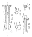
- FIG. 50 is a right side view in elevation, taken in longitudinal cross section of a sleeve incorporating a flap distal closure that is selectively actuated on a sleeve to shield a sharp tip;
- FIG. 51 is a front view in elevation of the distal flap closure and sharp tip of the obturator and sleeve of FIG. 50 ;
- FIG. 52 is a front view in elevation of an alternate distal flap closure with three flaps for the sleeve of FIG. 51 ;
- FIG. 53 is a right side view in elevation, taken in longitudinal cross section of a distal portion of the sleeve of FIG. 50 , with closed distal flap closure and an obturator with a protected sharp tip shown in phantom;
- FIG. 54 is a front view in elevation, taken in cross section along lines 54 - 54 of a proximal portion of the sleeve of FIG. 50 ;
- FIG. 55 is a right side view in elevation, taken in longitudinal cross section of a distal portion of an obturator having a lateral notch accentuated by an MRI visible marker and communicating with a marker deployment lumen;
- FIG. 56 is a right side view in elevation, taken in longitudinal cross section of a distal portion of an obturator having a lateral notch accentuated by flanking marker bands and communicating with an underlying vacuum lumen;
- FIG. 57 is a right side view in elevation, taken in longitudinal cross section of an obturator with a side notch with a deployment ramp and marker/tool lumen;
- FIG. 58 is a right side view in elevation, taken in longitudinal cross section of a core needle having an annular ring MRI visible marker about an open distal end that communicates with a longitudinal marker/tool lumen;
- FIG. 59 is a right side view in elevation, taken in longitudinal cross section of a sleeve with a distal opening and a side aperture that selectively communicates with a longitudinal lumen with an adapter positioned in a first position;
- FIG. 60 is a right side view in elevation, taken in longitudinal cross section of the sleeve of FIG. 59 with the adapter in a second position;
- FIG. 61 is a right side view in elevation of a curl-biased tool rotated to deflect tip up;
- FIG. 62 is a right side view in elevation taken in longitudinal cross section of a sleeve with the curl-biased tool tip extending through a side aperture of the sleeve;
- FIG. 63 is a right side view in elevation of the curl-biased tool of FIG. 61 rotated a half rotation to deflect tip down;
- FIG. 64 is a right side view in elevation taken in longitudinal cross section of the sleeve of FIG. 6 with the curl-biased tool tip extending through a distal opening of the sleeve;
- FIG. 65 is a right side view in elevation taken in longitudinal cross section of a sleeve having a push slide distally extended to direct a tool out a side aperture;
- FIG. 66 is a right side view in elevation taken in longitudinal cross section of the sleeve of FIG. 65 having the push slide retracted to allow the tool to extend out of a distal opening;
- FIG. 67 is a right side view in elevation taken in longitudinal cross section of the sleeve of FIG. 62 with a plug inserted into the distal end to divert a tool out the side aperture.
- FIG. 68 is a right side view in elevation taken in longitudinal cross section of a sleeve with an open distal end pneumatically sealed to a an obturator with an imagable side notch with an underlying MRI bright marker;
- FIG. 69 is a right side view in elevation taken in longitudinal cross section of the sleeve of FIG. 68 pneumatically sealed to a marker stylet with a side aperture accentuated by an underlying MRI bright marker and communicating with a marker/tool lumen proximally sealable by luer fitting a coupled cap/handle;
- FIG. 70 is a right side view in elevation taken in longitudinal cross section through the sleeve of FIG. 68 with a core needle stylet pneumatically sealed therein;
- FIG. 71 is a diagrammatic view of a process to produce polymide for an MRI biopsy device
- FIGS. 72A-7D are cross sectional views of a round, oval, square/rectangular, and complex-shaped sleeve
- FIG. 73A is a front view of a perform sleeve placed within a compression fixture
- FIG. 73B is a front view of the sleeve of FIG. 73A after lateral compression to form an oval cross sectional shape;
- FIG. 73C is a front view of the oval sleeve of FIG. 73B after heating to form a cohesive permanent shape
- FIG. 74A is a front view of a perform round sleeve positioned in a forming fixture of a waisted oval mandrel inserted through the sleeve and the sleeve placed between compression plates having opposing pinching portions;
- FIG. 74B is a front view of the perform round sleeve after compression and heating of the forming fixture of the compression plates against the mandrel with the perform sleeve trapped therebetween to acquire a waisted oval shape;
- FIG. 74C is a front view of the waisted oval sleeve after release from the forming fixture of FIG. 74B ;
- FIG. 74D is a front view of a forming fixture with compression plates and mandrel shaped to constrain the perform sleeve for compression and heating in a full circumference to form a waisted oval shape;
- FIG. 74E is a front view of the waisted oval shaped sleeve after release from the forming fixture of FIG. 74D ;
- FIG. 75 is a perspective view of a sleeve with laser formed proximal mounting holes for overmolding and side aperture;
- FIG. 76A is a right side view in elevation through a longitudinal cross section of a proximal portion of a sleeve having laser formed through holes over molded with a sleeve hub;
- FIG. 76B is a right side view in elevation through a longitudinal cross section of a proximal portion of a sleeve having a laser formed relieved area over molded to form a sleeve hub;
- FIG. 77 is a top diagrammatic view of a dual point flat blade attached in a slot in a conic distal piercing tip of an obturator or sleeve;
- FIG. 78A is a top diagrammatic view of a primary/secondary conic piercing tip of an obturator or sleeve;
- FIG. 78B is a front view in elevation of the primary/secondary conic piercing tip of FIG. 78A ;
- FIG. 79 is a geometric diagram of insertion torques for positive angles for the piercing tip of FIGS. 78A-78B ;
- FIG. 80 is a geometric diagram of insertion torques for negative angles for the piercing tip of FIGS. 78A-78B ;
- FIG. 81A is a perspective view of an alternate flat, triangular cutting member for a piercing portion of a sleeve or obturator;
- FIG. 81B is a top view of the alternate flat, triangular cutting member of FIG. 81A ;
- FIG. 82 is a left side view in elevation of an obturator with flat bladed piercing tip, lumen communicating between a lateral notch and fluid fitting on a proximal end with external engaging features for an obturator hub;
- FIG. 83 is a front view in elevation of the obturator of FIG. 82 ;
- FIG. 84 is a left side view in elevation of a longitudinal cross section of the obturator of FIG. 83 taken along lines 84 - 84 ;
- FIG. 85 is a front view in elevation of the obturator of FIG. 82 taken in cross section along lines 85 - 85 distal to a hub engaging portion;
- FIG. 86 is a front view in elevation of the obturator of FIG. 82 taken in cross section along lines 86 - 86 across the hub engaging portion;
- FIG. 87 is a right side view in elevation, taken in longitudinal cross section of the short fiducial instrument having a valve body attached to a hollow snout with a proximal fill spout sealed by a septum and proximally extending from the valve body and with the distal end of an elongate cavity in the hollow snout partially sealed by a porous plug; and
- FIG. 88 is a right side view in elevation, taken in longitudinal cross section of the long fiducial instrument having an integral valve body portion formed with a hollow snout portion with a proximal pipe fitting proximally extending from the valve body portion and with the distal end of an elongate cavity in the hollow snout portion partially sealed by a vent hole.
- a Magnetic Resonance Imaging (MRI) compatible biopsy system 10 includes a guide that guides a sleeve and introducer obturator that are separate from the biopsy device itself and advantageously incorporate an improved piercing portion, MRI imaging marker, and fluid handling capabilities. Mounting provisions allow for precise penetration along a desired trajectory without overshooting.
- MRI Magnetic Resonance Imaging
- the MRI compatible biopsy system 10 includes a control module 12 that typically is placed outside of a shielded room containing an MRI machine (not shown) or at least spaced away to mitigate detrimental interaction with its strong magnetic field and/or sensitive radio frequency (RF) signal detection antennas.
- the control module 12 controls and powers an MRI biopsy device 14 that is compatible for use in close proximity to the MRI machine.
- An example of an MRI biopsy device 14 is the afore-mentioned MAMMOTOMETM instrument.
- the MRI biopsy device 14 is accurately positioned by a localization fixture 16 that is attached to a breast coil 18 , which in turn supports a patient (not shown).
- a guidance assembly 20 and, in particular, a sleeve 22 , advantageously attaches to the localization fixture 16 to increase imaging and therapeutic flexibility and accuracy in conjunction with selective use of the MRI biopsy device 14 during particular parts of the procedure.
- the guidance assembly 20 may include one or more obturators 24 with one depicted that seals the sleeve 22 during insertion and during subsequent portions of the procedure in which the MRI biopsy device 14 is not inserted therein.
- a depth stop 26 is provided for use with the localization fixture 16 to advantageously prevent over-insertion of the sleeve 22 , inadvertent retraction of the sleeve 22 and/or to enhance accurate placement of the sleeve 22 to a desired location along the Z-Axis.
- a perforated barrier that is compressed along an outside side of the breast, with respect to a medial plane of the chest of the patient, defines an X-Y plane, with the X-axis being vertical (sagittal) with respect to a standing patient and which corresponds to a left to right axis as viewed by a clinician facing the externally exposed portion of the localization fixture 16 .
- a fiduciary marker (not shown)), attached to or positioned relative to the localization fixture 16 proximate to the patient's skin, defines the origin of this plane.
- Perpendicular to this X-Y plane and extending toward the medial side of the breast is the Z-axis, which typically corresponds to the orientation and depth of insertion of the MRI biopsy device 14 , although it should be appreciated that variations may allow insertion at an angle to this Z-axis.
- the term Z-axis may be used interchangeably with “axis of penetration”, although the latter may or may not be orthogonal to the spatial coordinates used to locate an insertion point on the patient.
- the MRI compatible biopsy system 10 is prepared for use by placing a cable management spool 30 upon a cable management attachment saddle 32 that projects from a side of the control module 12 .
- Wound upon the cable management spool 30 is a paired electrical cable 34 and mechanical cable 36 for communicating control signals and cutter rotation/advancement motions respectively.
- electrical and mechanical cables 34 , 36 each have one end connected to respective electrical and mechanical ports 40 , 42 in the control module 12 and another end connected to a holster 44 that receives the MRI biopsy device 14 .
- An MRI docking cup 46 which may hold the holster 44 when not in use, is hooked to the control module 12 by a docking station mounting bracket 48 .
- An interface lock box 50 mounted to a wall, provides a tether 52 to a lockout port 54 on the control module 12 .
- the tether 52 is advantageously, uniquely terminated and of short length to preclude inadvertent positioning of the control module 12 too close to the MRI machine.
- An in-line enclosure 56 may advantageously register the tether 52 , electrical cable 34 and mechanical cable 36 to their respective ports 54 , 40 , 42 on the control module 12 .
- a remote keypad 58 may be distally connected to the electrical cable 34 to enhance clinician control of the MRI biopsy device 14 , especially when controls on the MRI biopsy device 14 itself are not readily accessible after insertion into the localization fixture 16 .
- Vacuum assist is provided by a first vacuum line 60 that connects between the control module 12 and an outlet port 62 of a vacuum canister 64 that catches liquid and solid debris.
- a tubing kit 66 completes the pneumatic communication between the control module 12 and the MRI biopsy device 14 .
- a second vacuum line 68 is connected to an inlet port 70 of the vacuum canister 64 .
- the second vacuum line 68 divides into two vacuum lines 72 , 74 that are attached to the MRI biopsy device 14 .
- the control module 12 performs a functional check. Saline is manually injected into biopsy device 14 to serve as a lubricant and to assist in achieving a vacuum seal.
- the control module 12 actuates a cutter mechanism (not shown) in the MRI biopsy device 14 , monitoring full travel.
- the portion of the MRI compatible biopsy system 10 used near the MRI machine is also assembled.
- the generally known breast coil 18 is placed upon a gantry of the MRI machine, along with other body support pads (not shown).
- the localization fixture 16 which is attached within a recess on either lateral side of the breast coil 18 to access a patient's breast that is pendulously exposed therein, includes a horizontal medial plate 80 , a reusable base assembly 82 , a lateral assembly 84 , and a positioning pedestal 86 .
- the localization fixture 16 is also assembled with a disposable medial fence 90 and a lateral window (or perforated plate) 92 .
- the base assembly 82 is placed within a selected lateral recess of the breast coil 18 .
- the medial fence 90 attaches to a medial edge of the medial plate 80 , aligned vertically approximately along a longitudinal axis of the breast coil 18 under an inner edge of a selected breast aperture 94 that receives a patient's breast.
- the lateral window 92 is downwardly slid into a three-sided frame guide 96 of the lateral assembly 84 , which in turn is placed upon the medical plate 80 .
- the base assembly 82 and lateral assembly 84 are moved with respect to one another along the Z-axis to compress the patient's breast between the medial fence 90 and the lateral window 92 .
- a mechanism formed between the lateral assembly 84 , base assembly 82 , and medial plate 80 maintains this compression.
- Contrast agent may be injected into the patient to enhance the imaging.
- the gantry is advanced into the MRI machine bore to image the localization fixture 16 and breast tissue.
- the fiduciary marker on the lateral window 92 is located and designated as the origin of the X-Y-Z coordinates.
- a suspicious lesion is located within the image and a point thereon selected to determine its location relative to the origin. It should be appreciated that orienting the X-Y-Z axis of an initial scan may be facilitated by having the lateral window 92 formed of an imagable material, thus presenting an X-Y plane in addition to the origin point of the fiduciary marker. With the target location determined, the gantry is withdrawn from the MRI machine bore.
- the positioning pedestal 86 is slidably engaged along the X-axis of the lateral assembly 84 and defines a vertical guide for positioning a single targeting rail (“track”) 98 at a selected Y-axis coordinate.
- the track 98 in turn provides a depth guide along the Z-axis for positioning the depth stop 26 and the holster 44 at a desired Z-axis coordinate.
- the depth stop 26 is latched onto the track 98 . Thereafter, a marking instrument (not shown) may be inserted through the depth stop 26 to mark the insertion point on the breast. Thereafter, the depth stop 26 is moved out of the way. Anesthesia is injected superficially, followed by a scoring cut at the marked location and a subsequent injection of anesthesia more deeply into the scored cut. The depth stop 26 is then repositioned on the track 98 to the desired Z-axis coordinate reference.
- the obturator 24 is inserted into the sleeve 22 and may be positioned to close any apertures of the sleeve 22 (side and/or distal end) to present a closed surface to the breast tissue.
- the obturator may also be shaped or formed to enhance the visibility of the aperture location.
- One or the other of the obturator 24 and sleeve 22 presents a sharp tip (not shown) to penetrate breast tissue. For instance, if using a sleeve 22 having an open end, an obturator may provide a sharp tip.
- the obturator 24 is inserted into the sleeve 22 and the combination is guided by the track 98 to a proper orientation until an accurate depth is reached as set by the depth stop 26 . Once fully inserted, the depth stop 26 prevents over-insertion.
- the sleeve 22 advantageously latches to the track 98 and/or the depth stop 26 to prevent inadvertent retraction, such as when the obturator 24 is withdrawn, and pressure is received from the breast tissue or later when a probe 100 of the MRI biopsy device 14 is withdrawn from the sleeve 22 .
- imagable materials of the sleeve 22 and/or obturator 24 enhance the ability to confirm the location of the sleeve 22 and its sleeve side aperture 102 as positioned for subsequent biopsy samples.
- the patient is removed from the MRI machine by retracting the gantry and the holstered MRI biopsy device 14 is brought to the localization fixture 16 .
- a protective cap (not shown) is removed from the probe 100 of the MRI biopsy device 14 and the obturator 24 is removed from the sleeve 22 .
- Mounting of the holster 44 to the track 98 is shown in FIGS. 2 and 3 , wherein the holster 44 and MRI biopsy device 14 combination slide onto the track 98 that has been positioned at a certain location with respect to the pedestal 86 and lateral assembly 84 .
- the sleeve 22 and probe 100 may advantageously visually and mechanically orient a probe side aperture 104 of the probe 100 with the sleeve side aperture 102 , as well as forming a gas seal.
- the holster 44 and/or the probe 100 may latch onto the track 98 or sleeve 22 to confirm full insertion and prevent over-insertion and inadvertent retraction.
- the holster 44 allows an MRI biopsy device 14 , intended for handheld use, to have sufficient support in its attachment to the localization fixture 16 to accurately maintain its position and to avoid or minimize loads carried by the probe 100 .
- the MRI compatible biopsy system 10 may take tissue samples by activating a cutter mechanism in conjunction with vacuum assist, withdrawing the cutter and withdrawing a tissue sample, the latter perhaps also with vacuum assist.
- the probe 100 /sleeve 22 combination is capable of manual, or perhaps automatic, rotation to a desired angle with respect to their longitudinal axis for additional samples or additional samples may be taken at the current orientation by further resorting to vacuum assist.
- the cutter is then advanced to close the probe side aperture 104 and the holster 44 is withdrawn from the localization fixture 16 , thereby removing the probe 100 from the sleeve 22 .
- Additional steps or combinations of steps may be performed at this point, such as using the probe 100 , a specialized obturator 24 (e.g., stylet), or merely the sleeve 22 to guide various agents to the surgical site of the biopsy. Examples include draining fluids, inserting anesthetic agents, inserting hemostatic agents, insufflating with pneumatic pressure and inserting a marker for subsequently locating the site of the biopsy, or other diagnostic or therapeutic procedures.
- the patient is then typically drawn back into the MRI machine bore for reimaging to confirm removal of at least a portion of the suspicious lesion and possibly placement of a marker.
- the sleeve 22 is sealed with the obturator or stylet 24 .
- the localization fixture 16 is removed, the patient is bandaged and removed from the gantry, and the disposable portions of the MRI compatible biopsy system 10 are disposed of as medical waste.
- the single targeting rail 98 facilitates sequential mounting of separate components. First, the depth stop 26 , then the sleeve 22 (as in FIG. 1 ), and then the biopsy tool 14 is slid onto the single targeting rail 98 . Alternatively as depicted in FIGS. 2-3 , the single targeting rail 98 may receive the depth stop 26 and then an MRI biopsy device 14 is used without a separate sleeve 22 . The maximum depth of penetration into the patient's breast is preset by the location of the depth stop 26 on the single targeting rail 98 .
- An engagement mechanism between the holster 44 and the single targeting rail 98 (not shown) and/or an engagement mechanism formed by a catch, depicted as an upwardly projecting pin 110 , on an upper rail-gripping arm 112 of the depth stop 26 and a downwardly spring-biased rocker latch 114 that snaps onto the upwardly projecting pin 110 , preventing inadvertent retraction of the MRI biopsy device 14 .
- the holster 44 may be disengaged by downward pressure on a proximal actuating arm 116 of the rocker latch 114 .
- the single targeting rail 98 may be longitudinally sized to extend proximally sufficiently so that the MRI biopsy device 14 engages the single targeting rail 98 prior to the probe 100 contacting the patient's skin.
- the single targeting rail 98 is also sized to not extend proximally to the extent that it would preclude use in a closed bore MRI machine (not shown).
- Such an MRI compatible biopsy system 10 is believed to minimize the procedure turn-around time to less than 45 minutes as described above.
- a radiologist may position the probe 100 accurately to within 2 mm (5 mm maximum) of the lesion center. Further, the radiologist may maximize access to both breasts (left or right) during a procedure (both sides of the table) with minimal repositioning of the patient. Further, a minimal amount of force is needed to penetrate tissue, such as less than 4 lbs.
- the depth stop 26 serves to prevent overshooting, features for repositioning the depth stop 26 prior to further insertion of the probe 100 allow clinical flexibility in targeting another location.
- an alternative guidance assembly 200 for the MRI compatible biopsy system 10 incorporates a cradle 202 that attaches to a targeting rail 204 and provides a biopsy rail 206 for supporting the MRI biopsy device 14 , both rails 204 , 206 aligned to the Z axis.
- the targeting rail 204 is attached to the positioning pillar 86 (not shown in FIG. 4 ) and is vertically adjusted to a desired Y-position.
- a circular attachment point 208 may form a rotational engagement to the positional pedestal 86 to allow an angled targeting guide.
- a lateral face 210 of the targeting rail 204 includes an upper flange 212 and a lower flange 214 , each having an L-shaped cross section for slidingly receiving a sleeve mount 216 .
- Vertical rows of laterally projecting ridges 218 in each flange 212 , 214 serve as a locking surface for the sleeve mount 216 .
- a side channel 220 is recessed therein.
- the sleeve mount 216 guides a sleeve 222 by having its sleeve hub 224 proximally received in a hub receptacle 225 of the sleeve mount 216 and is distally positioned and constrained by a depth stop 226 .
- the depth stop 226 includes a slide member 228 that engages the side channel 220 .
- a depth stop housing 230 attaches thereto, terminating in a reticule 232 .
- a locking lever 234 is vertically pinned within a distally open recess (not shown), defined in the depth stop 226 with a lateral portion 236 spring biased away therefrom such that distally projecting feet 238 pivot against and engage the ridges 218 , especially against a proximal movement. Depressing the lateral portion 236 proximally against the distally open recess of the depth stop housing 230 releases the distally projecting feet 238 to allow repositioning the depth stop 226 distally.
- An axis of penetration of the biopsy device 14 is aligned with the axes defined by the targeting rail 204 and the biopsy rail 206 , which are laterally and vertically orthogonally offset therefrom, respectively. Extending a horizontal plane from the targeting rail 204 and extending a vertical plane from the biopsy rail 206 intersect at a common centerline that is the axis of penetration. Having the biopsy rail 206 vertically aligned and parallel to the axis of penetration advantageously provides support for the weight of the biopsy device 14 with a minimum of torsion loads that may otherwise create deflections of an inserted distal end.
- the cradle 202 below the axis of penetration pedestal 86 in the illustrative version may be replaced by one vertically displaced above the axis of penetration.
- a bottom dovetail channel 240 in the targeting rail 204 receives a top dovetail extension 242 on the cradle 202 , which is slid therein. It should be appreciated that mounting is shown herein on the right side of the positioning pedestal 86 when viewed proximally, but that the guidance assembly 200 advantageously comprises symmetric parts that allow mounting and use on either side of the positioning pedestal 86 to increase flexibility in positioning the probe 100 .
- a horizontal base 244 of the cradle 202 forms the biopsy rail 206 as a biopsy guide channel 246 flanked by a first and second pair of monocle receptacles 248 , 250 so that a pair of locking hooks 252 on a monocle 254 may be inserted in either pair of monocle receptacles 248 , 250 , depending on which is closer to the patient.
- a cradle may be directly attached to the positioning pedestal 86 (not shown).
- the cradle 202 is mechanically robust and can support the gross weight of the MRI biopsy device 14 . Since the MRI biopsy device 14 does not share the cradle 202 , the cradle 202 may be optimized to support the MRI biopsy device 14 when either shallow or deep lesions need to be accessed.
- a guide bushing 256 inserted in a monocle reticule 258 guides a marking instrument and/or a scoring scalpel (not shown) as an initial step in locating and preparing an insertion point.
- the monocle 254 may be removed thereafter or left in place to guide the sleeve 222 in addition to the reticule 232 of the depth stop 226 , the latter which may also hold a guide bushing 260 for guiding the sleeve 222 .
- Removing the guide bushings 256 , 260 allows for the reticules 258 , 232 of the monocle 254 and depth stop 226 to guide a larger component, such as a fiducial 262 used for locating a suspicious lesion relative to the guidance assembly 200 .
- the alignment of the sleeve 222 is maintained by first passing through the hub receptacle 225 of the sleeve mount 216 , which receives the sleeve hub 224 .
- the sleeve 222 has an open ended shaft 266 for receiving an introducer obturator 268 that includes a piercing tip (e.g., flat blade) 270 at a distal end of solid obturator shaft 272 .
- a beveled recess 276 into the solid obturator shaft 272 is aligned with a sleeve side aperture 278 of the sleeve 222 , and thus ultimately of the probe 100 ( FIGS. 1-3 ).
- the materials of the obturator 268 may be selected to aid in locating the sleeve side aperture 278 of the sleeve 222 , which otherwise may be more difficult to visualize and locate in an MRI scan slice.
- the sleeve hub 224 has its proximal cylindrical edge 280 attached to a guidance thumbwheel 282 that proximally extends from the hub receptacle 225 of the sleeve mount 216 for rotating the sleeve 222 to position its sleeve side aperture 278 with reference to a visual mark, depicted as a locking slot 284 , on the thumbwheel 282 corresponding thereto.
- the thumbwheel 282 includes a central through hole 286 sealed by a wiper seal 288 and a duckbill seal 290 trapped between the thumbwheel 282 and the proximal cylindrical edge 280 of the sleeve hub 224 .
- insertion of the obturator 268 which includes a locking tab 292 that enters the locking slot 284 , closes the central through hole 286 and forms a dynamic seal against the wiper seal 288 .
- a stylet 298 may be inserted into the sleeve 222 so that a proximally presented hose nib 300 of the stylet 298 may be used to insufflate the surgical site or used for other purposes such as draining bodily fluids or inserting therapeutic or diagnostic agents through a stylet shaft 302 of the stylet 298 to a stylet side aperture 304 that is aligned with the side aperture 278 of the sleeve 222 .
- the stylet 298 also includes a locking tab 306 .
- the sleeve mount 216 includes a downwardly spring-biased rocker latch 308 that snaps onto a ramped catch 310 on the depth stop 226 , preventing inadvertent retraction of the sleeve 222 .
- the sleeve mount 216 may be disengaged by downward pressure on a proximal actuating arm 312 of the rocker latch 308 .
- An upwardly spring-based rocker latch 314 attached to the bottom of the sleeve mount 216 , similarly engages the depth stop 226 .
- the sleeve mount 216 may be distally advanced without overshooting and subsequently may be held in place when removing implements therefrom such as the obturator 268 , stylet 298 , and MRI biopsy device 14 .
- a further alternative guidance assembly 400 for the MRI compatible biopsy system 10 includes a cradle 402 that engages a bottom channel 403 of a primary targeting rail 404 .
- a secondary targeting rail 406 includes a lateral channel 408 that is guided along a longitudinal guide tab 410 of the primary targeting rail 404 .
- a pawl 412 pivoting under urging of a pawl spring 414 about a vertical pawl pin 416 in a lateral window 418 proximally positioned in the secondary targeting rail 406 , drops into a proximal detent 420 proximally positioned on the primary targeting rail 404 .
- a sleeve 422 includes a hollow shaft (or cannula) 423 that is proximally attached to a cylindrical hub 424 and has a lateral aperture 426 proximate to an open distal end 428 .
- the cylindrical hub 424 has an exteriorly presented thumbwheel 430 for rotating the lateral aperture 426 .
- the cylindrical hub 424 has an interior recess 432 that encompasses a duckbill seal 434 , wiper seal 436 and a seal retainer 438 to provide a fluid seal when the shaft 423 is empty and to seal to an inserted introducer obturator 440 .
- a hollow shaft 442 includes a fluid lumen 444 that communicates between a side opening 446 and a proximal port 448 .
- the hollow shaft 442 is longitudinally sized to extend a piercing tip 449 , when fully engaged, out of the distal end 428 of the sleeve 422 .
- An obturator thumbwheel cap 450 encompasses the proximal port 448 and includes a locking feature 452 , which includes a visible angle indicator 454 , that engages the sleeve thumbwheel 430 to ensure that the side opening 446 is registered to the lateral aperture 426 in the sleeve 422 .
- An obturator seal cap 456 may be engaged proximally into the obturator thumbwheel cap 450 to close the fluid lumen 444 .
- the obturator seal cap 456 includes a locking feature 458 that includes a visible angle indicator 459 that corresponds with the visible angle indicator 454 on the obturator thumbwheel cap 450 .
- the sleeve 422 is guided, during penetration of tissue, by a sleeve mount 460 having a sleeve hub 462 that receives the cylindrical hub 424 of the sleeve 422 .
- the sleeve mount 460 has a lateral sleeve hub channel 464 that slides along top and bottom guide flanges 466 , 468 of the secondary targeting rail 406 , each having an aligned and recess ridged, ratcheting surface 470 that interacts with a respective top and bottom ratcheting feature 472 , 474 on respective top and bottom rail lock rocker latches 476 , 478 that are engaged by respective top and bottom latch pins 480 , 482 in respective sides of the sleeve mount 460 .
- the ratcheting features 472 , 474 are proximally ramped such as to allow distal movement. Distal portions of each rail lock rocker latches 476 , 478 are biased away from the sleeve mount 460 by respective rail lock compression springs 484 , 486 to bias the ratcheting features 472 , 474 into contact with the ridges surfaces 470 of the guide flanges 466 , 468 .
- Simultaneous depression of the rail lock rocker latches 476 , 478 allow the sleeve mount 460 to be drawn proximally, withdrawing any sleeve 422 supported therein, until the sleeve mount 460 reaches a proximal end of the secondary targeting rail 406 , whereupon the sleeve mount 460 rotates the pawl 412 clockwise (as viewed from the top) and is thus engaged to the secondary targeting rail 406 as the secondary targeting rail 406 is unlocked from the primary targeting rail 404 , causing removal therefrom with continued proximal movement.
- a depth guide 490 is formed by a crescent-shaped depth indicator 492 having a lateral channel 496 shaped to engage the top and bottom guide flanges 466 , 468 .
- Forward ramped surfaces 498 on the top and bottom of the lateral channel 496 are positioned to engage the ridged ratcheting surfaces 470 on the secondary targeting rail 406 , allowing assembly by inserting the depth indicator 492 from a distal end of the secondary targeting rail 406 .
- Frictional engagement thereafter resists further proximal movement and strongly opposes any distal movement, especially from a depth lead screw 500 of the depth guide 490 , whose distal end 502 rotates within an outboard hole 504 in the depth indicator 492 and whose proximal end deflects laterally as a depth actuator lever 505 is used to rotate and longitudinally position the depth lead screw 500 therein.
- a mid portion of the depth lead screw 500 is received in a longitudinal through hole 506 formed in the sleeve mount 460 outboard to its lateral channel 408 .
- outer lead threads 507 on the depth lead screw 500 selectively engage the sleeve mount 460 until top and bottom coarse adjust buttons 508 , 510 are inwardly depressed into the sleeve mount 460 , compressing respective top and bottom coarse adjust compression springs 512 , 514 .
- Each coarse adjust button 508 , 510 includes a respective vertically elongate aperture 516 , 518 whose inward surface presents a worm gear segment 520 , 522 to engage the outer lead threads 507 on the depth lead screw 500 when urged into engagement by relaxed coarse adjust compression screws 512 , 514 .
- a separate sleeve and obturator capability provides even additional clinical flexibility. It should be appreciated, that various combinations of features may be selected for specific applications or preferences. Having a side aperture in a sleeve, corresponding to a sample-taking side aperture in the biopsy device, is often desirable. For instance, an open ended probe or biopsy needle that is inserted by necessity into a suspicious lesion may create hematomas that fill with residual contrast agent making it difficult to perform further imaging studies at that site. For another, piercing a suspicious lesion may pose a risk of track metastasis. Further, the tip of such a needle or probe may be difficult to image with respect to the suspicious lesion to accurately locate the latter, being essentially a point.
- a side aperture 600 of a sleeve 602 may be positioned beside a suspicious lesion so that a piercing tip 604 need not pass through the suspicious lesion. Locating this side aperture 600 in an MRI scan slice would seem to be easier in that the side aperture 600 defines a line that more readily allows orienting an imaging slice along its length with a geometric reference that readily shows from what direction tissue may be drawn into the side aperture 600 for biopsying. However, slices that are not ideally oriented or that pass through MRI compatible materials that may form the sleeve 602 may still complicate accurate and expedient identification of the side aperture 600 . To assist in this identification, an obturator 606 assists during introduction of the sleeve 602 by substantially or completely blocking the side aperture 600 so that tissue does not prolapse into the side aperture 600 and impede insertion and/or cause tissue trauma.
- the obturator 606 thus advantageously includes the piercing tip 604 that extends distally out of the distal opening 608 in the sleeve 602 .
- the obturator 606 further has a lateral recess (e.g., notch, bevel, canoe dug-out) 610 aligned with the side aperture 600 in the sleeve 602 when the obturator 606 is fully inserted therein. Being radially asymmetric, this lateral recess 610 provides a rapidly acquired and interpreted reference for locating the side aperture 600 .
- a side aperture 620 is formed in a sleeve 622 that has a closed distal end 628 that forms or supports a piercing tip 624 .
- An obturator 626 serves to shape the prolapse of tissue into the side aperture 600 during introduction and includes a lateral recess (e.g., notch, bevel, canoe dug-out) 630 aligned with the side aperture 620 in the sleeve 622 when the obturator 626 is fully inserted therein.
- a lateral recess e.g., notch, bevel, canoe dug-out
- an obturator 646 includes a piercing tip 644 that extends out of the distal opening 608 in the sleeve 602 of FIG. 6 .
- the obturator 646 creates a distinctive cross section by having an upper longitudinal portion 649 and a lower longitudinal portion 651 .
- the upper longitudinal portion 649 is shaped to control the prolapse of tissue into the side aperture 600 as well as present a readily located reference for an MRI scan slice.
- the sleeve 622 of FIG. 7 with the closed distal end 628 formed into or supporting the piercing tip 624 , is shown having its side aperture 620 closed during introduction by an obturator 656 having a distinctive cross section showing an upper longitudinal portion 659 and a lower longitudinal portion 661 .
- the upper longitudinal portion 649 has a cross sectional profile that is designed to shape the prolapse of tissue into the side aperture 620 as well as present a readily located reference for an MRI scan slice.
- a sleeve 702 has a side aperture 700 and a closed distal end 708 which are formed into an asymmetric piercing tip 704 that encompasses an obturator 706 .
- the obturator 706 has a continuous profile formed by an upper longitudinal portion 709 and a lower longitudinal portion 711 that create a distinctive cross section, such as an X-shape as depicted in FIGS. 11-12 .
- the obturator 706 may have a distinctive cross section such as an upward longitudinal spine 715 attached to a lower longitudinal half-cylinder 717 as depicted in FIGS. 13-14 . It should be appreciated that the prolapse of tissue at the side aperture 700 provides an MRI image return whereas in other portions of the obturator 706 , the air spaces between the sleeve 702 and the obturator 706 appear similarly dark.
- an obturator 806 includes a lateral notch 810 proximate to a piercing tip 804 .
- an MRI visible insert 807 e.g., an aqueous gel
- an obturator 826 may include a proximally accessed marker lumen 827 through which a marker insert 829 may be inserted proximate to a distal piercing tip 824 .
- an obturator 846 includes a vacuum lumen 848 that communicates with a lateral notch 850 to draw in sufficient bodily fluids 851 to present an MRI visible image of the side aperture of the sleeve (not shown).
- the obturator 846 employs vacuum assist through the vacuum lumen 848 to prolapse tissue 853 into the lateral notch 850 to present an MRI visible image.
- the obturator 846 further includes a thin sheath 855 that is slid overtop of the lateral notch 850 to capture an MRI visible material (e.g., aqueous fluid, gadolinium solution, etc.) 857 .
- an MRI visible material e.g., aqueous fluid, gadolinium solution, etc.
- an obturator 876 includes a solid stylet insert 879 substantially encompassed by a cylindrical sheath 877 , except for over a lateral notch 881 formed in the solid stylet insert 879 .
- the cylindrical sheath 877 is distally attached to a ceramic asymmetric piercing tip 874 .
- an obturator 896 has an open distal end 894 and a lateral aperture 890 with vacuum assisted air evacuation proximally from a marker lumen 893 formed therein, allowing the marker lumen 893 to fill with bodily fluids to present an MRI visible material.
- an obturator 906 has a piercing distal end 0904 and a lateral aperture 0900 with vacuum assisted air evacuation to allow a marker lumen 903 to fill with bodily fluids to present an MRI visible material.
- an obturator 916 has a closed, blunt distal end 914 and a marker lumen 918 containing an MRI visible material (e.g., gadolinium solution, aqueous solution) 911 .
- An MRI dark plug 913 e.g., collagen, nonferrous metal, plastic
- the MRI dark plug 913 contains longitudinal fluid leak passages 915 to allow MRI bright images to be formed to each side of the side aperture within the marker lumen 918 .
- an obturator 926 has a piercing distal end 924 and a marker lumen 928 containing an MRI visible material (e.g., gadolinium solution, aqueous solution) 921 .
- An MRI dark plug (e.g., collagen, nonferrous metal, plastic) 923 is positioned to correspond to a side aperture of a sleeve (not shown in FIG. 24 ).
- the MRI dark plug 923 contains longitudinal fluid leak passages 925 to allow MRI bright images to be formed to each side of the side aperture within the marker lumen 928 .
- an obturator 936 has a piercing distal end 934 and a marker lumen 938 containing an MRI visible material (e.g., gadolinium solution, aqueous solution) 931 .
- a side aperture 930 communicates with the marker lumen 938 via fluid leak passages 935 formed in an MRI dark plug (e.g., collagen, nonferrous metal, plastic), 933 otherwise blocking the marker lumen 938 .
- an MRI dark plug e.g., collagen, nonferrous metal, plastic
- FIGS. 26-37 further illustrative versions of the shape of a sleeve and obturator are depicted that advantageously enhance the ability to locate suspicious lesions and to confirm proper placement of the side aperture thereof prior to taking biopsy samples by presenting a closed shape during penetration that may be changed to a shape that corresponds to a relieved area where samples will be taken, this shape visibly solid so as to be readily recognizable even when viewed from various angles of imaging slices.
- This feature addresses drawbacks from relying upon the probe for imaging. Having a metallic substance in the imaging field may cause an artifact (local blooming) that may obscure the tissue of interest, such as attempting to use the biopsy probe itself to obturate the sleeve. Removing the probe during imaging and relying upon only the sleeve allows another imaging challenge to occur as an imaging slice through the hollow sleeve 22 may pose difficulties in identifying the side aperture. Often, the MRI compatible material selected gives no MRI return image, just as an air-filled void present across a side aperture thus presenting no return.
- an MRI compatible biopsy system 1210 includes a sleeve 1222 having a notch 1202 that corresponds to the location and size of the probe side aperture of the probe of the MRI biopsy device (not shown in FIG. 26 ). Moreover, the depth of the notch 1202 may be deeper than the probe side aperture in some instances to accentuate this location on the sleeve 1222 for imaging purposes.
- An obturator 1224 shown in phantom in FIG. 26 in its “closed position” substantially blocking the notch 1202 of the sleeve 1222 , may be advantageously formed of a thermoplastic as described with a distally presented ceramic bladed portion 1220 that extends through an open distal end 1221 of the sleeve 1222 . Ceramic materials perform well in an MRI environment and hold a sharpened edge. With the notch 1202 closed by the coaxially inserted obturator 1224 , the sleeve 1222 may be inserted into breast tissue.
- the obturator 1224 depicted advantageously includes a longitudinally bifurcated design as shown in FIGS. 28-29 wherein the lower portion 1223 includes a dovetail channel 1225 down its length that slidingly engages a dovetail tab 1227 extending down from an upper portion 1229 of the obturator 1224 .
- the ceramic bladed portion 1220 is attached only to the lower portion 1223 .
- the upper portion 1229 may be proximally moved with the lower portion 1223 fully distally inserted into the sleeve 1222 to thereby open the notch 1202 of the sleeve 1222 .
- the obturator 1224 is solid, during the 3-4 mm image slices taken by the MRI machine, the lower portion 1223 of the obturator 1222 fills in the notch 1202 so that its location may be readily ascertained.
- This two-piece obturator 1224 advantageously accommodates sleeve lumens with complex cross sectional shapes, such as the depicted oval-shaped sleeve 1222 ( FIG. 27 ).
- a sleeve 1322 includes an integral sharp 1320 distally attached to its shaft 1319 that defines a circular cutter lumen 1321 and an underlying vacuum lumen 1323 ( FIG. 31 ).
- a round obturator 1324 is generally rod-shaped for insertion into the cutter lumen 1321 but with a notch recess 1325 formed corresponding to a notch 1302 of the sleeve 1322 ( FIG. 30 ).
- the notch recess 1325 may be selectively presented to open the notch 1302 in the sleeve 1322 or rotate about half a revolution to close the notch 1302 .
- FIGS. 34-35 The resulting effect in an MRI image scan is illustrated in FIGS. 34-35 wherein selectively closing the notch 1302 in the sleeve 1322 with the obturator 1324 presents a solid image but with little indication of where the notch 1302 is oriented.
- FIGS. 36-37 With the obturator 1324 rotated to open the notch 1302 , it is readily apparent where the notch 1302 is oriented.
- the obturator 1424 may selectively proximally attach to the sleeve 1422 to prevent inadvertent retraction and to assist maintaining a pneumatic/fluid seal with a bayonet-style attachment 1430 formed by cleats 1432 radially projecting from a cylindrical base 1434 of the obturator 1424 that is received within L-shaped recesses 1436 registered within a proximal bore 1438 of a sleeve lumen 1440 of the sleeve 1422 .
- FIG. 38 the obturator 1424 may selectively proximally attach to the sleeve 1422 to prevent inadvertent retraction and to assist maintaining a pneumatic/fluid seal with a bayonet-style attachment 1430 formed by cleats 1432 radially projecting from a cylindrical base 1434 of the obturator 1424 that is received within L-shaped recesses 1436 registered within a proximal bore 1438 of a
- a threaded attachment 1450 is formed by male threads 1452 about a cylindrical base 1454 of an obturator 1424 a that is threadingly received by female threads 1456 about a proximal bore 1458 of a sleeve lumen 1460 of a sleeve 1422 a .
- a button release attachment 1470 is formed by locking hooks 1472 radially exposed about a cylindrical base 1474 of an obturator 1424 b that are asserted into a proximal bore 1478 of a sleeve lumen 1480 of a sleeve 1422 b .
- the locking hooks 1472 engage a ramped recess 1481 in the proximal bore 1478 , holding the obturator 1422 b in its distal longitudinal position.
- a respective one of a pair of buttons 1476 extends through a respective ramped recess 1481 , initially forced outward upon insertion of the locking hooks 1472 .
- a user may depress the buttons 1476 while exerting a proximal pressure on the obturator 1424 b to disengage the locking hooks 1472 .
- Additional therapeutic and diagnostic abilities are provided by use of a sleeve that is separate and apart, but is used in conjunction with an MRI biopsy device. This utility is enhanced by incorporating fluid and pneumatic seals within the sleeve so that bodily fluids may be selectively drained, anaesthesia or other medical compounds may be inserted into the surgical site of the biopsy, insufflation or deflation of the surgical site may occur, and/or vacuum assist of the MRI compatible biopsy system may be maintained.
- a sleeve 1522 incorporates a full-diameter seal, or septum 1523 , across a proximal bore opening 1524 to a sleeve lumen 1526 .
- a degree of pneumatic pressure e.g., insufflation
- the sleeve 1522 advantageously incorporates a port 1530 in its base that communicates with a distal portion 1528 of the sleeve lumen 1526 to a side aperture 1502 for purposes such as draining fluids or adding anaesthesia.
- a similar sleeve 1522 a incorporates an O-ring dynamic seal 1550 instead of the full-diameter seal that forms a seal with an obturator 1524 , which may advantageously include a groove or passage 1552 down its length to allow fluid communication between the port 1530 and side aperture 1502 .
- a similar sleeve 1522 b incorporates a more distal O-ring dynamic seal 1560 and port 1562 to the proximal O-ring dynamic seal 1550 and proximal port 1530 .
- An obturator 1524 b may advantageously have two grooves or passages 1570 , 1572 that communicate between a respective port 1530 , 1562 and a respective side aperture 1502 and open distal end 1574 .
- an obturator 1600 includes a sharp piercing tip 1602 that is advantageously shielded when not being employed to pierce tissue by a cylindrical sheath 1604 . Thereby, the hazard of inadvertent injury and equipment damage is mitigated.
- the cylindrical sheath 1604 passes through a seal retainer 1608 and is captured within a duckbill seal 1610 held between the seal retainer 1608 and a sleeve hub 1612 .
- the piercing tip 1602 passes on through the sleeve hub 1612 and on through a cannula 1614 of the sleeve 1606 . It should be appreciated that upon retraction of the obturator 1600 , the piercing tip 1606 passes into the sheath 1604 and draws the sheath 1604 out of the sleeve hub 1612 .
- an alternate obturator 1630 has a sharp piercing tip 1632 selectively shielded by a sheath 1634 that may be stowed proximally in a cylindrical relieved area 1636 so that the sheath 1634 conforms to an outer diameter of a shaft 1638 of the obturator 1630 .
- a proximal control (not shown) actuates the sheath 1634 distally, either while inside of a sleeve 1640 as depicted or when the obturator 1630 is removed therefrom.
- the piercing tip 1632 is depicted as including a flat cutting blade 1642 that, at its base, extends the full diameter of the obturator shaft 1638 .
- a distal portion 1644 of the sheath 1634 is split to pass on either side of the flat cutting blade 1642 ( FIG. 49A ).
- the sleeve may be formed advantageously of a polymeric material, either homogenous or a composite, that is strong yet with thin walls so that the overall outer diameter need not be significantly larger than known biopsy probes, thereby being minimally invasive.
- the strength and small cross sectional area minimizes the size of the opening through the skin and thus typically avoids the need for sutures to close, reduces the force required to insert the probe, and minimizes trauma to breast tissue penetrated enroute to a suspicious lesion.
- the strength and rigidity advantageously maintain an open lumen for subsequent biopsy and other procedures therethrough.
- the sleeve is advantageously formed from materials that are biologically compatible to the patient and MRI compatible. Generally, the material thus does not create significant imaging artifacts that would obscure tissue images proximate to the sleeve 22 .
- polymeric materials examples include polyimide, polyetherimides (e.g., ULTEM®TM resin by GE PLASTICS), thermoplastic liquid crystal polymers (LCP) (e.g., VECTRA®TM by CELANESE AG), polyethylether ketones (e.g., PEEKTM by VITREX), polyamide, polycarbonate (e.g., MAKROLON by BAYER POLYMERS), polysulfone, polyethersulfone, polyphenylsulfone (e.g., RADEL®TM by ROWLAND TECHNOLOGIES), and nylon and nylon copolymers.
- an obturator 1660 with a piercing tip 1662 has a protective sheath 1664 drawn proximally by interference with a sleeve hub 1666 of a sleeve 1667 ( FIG. 50 ).
- Inward guide ridges 1668 of a proximal portion of the sheath 1664 move along guide slots 1670 formed in a shaft 1672 of the obturator 1660 .
- a distal portion of the sheath 1664 includes a plurality of radially spaced longitudinal slits 1674 to form a plurality of protective flaps 1676 (e.g., four flaps in FIG. 51 and three flaps in FIG.
- the inward bias of the protective flaps 1676 may be imparted to the sheath 1664 formed of spring metal, molded polymer, shape memory alloy annealed in closed position, etc.
- a piercing member (e.g., probe, multi-function obturator) 1700 has piercing tip 1702 as described below with regard to FIGS. 77-80B .
- a lateral notch 1704 is accentuated by an underlying MRI visible marker 1706 and communicates with a lumen 1708 that may be used for aspiration, hemostasis, introduction of anesthesia or pharmacological compound, and/or a marking material.
- Leading and trailing edges 1710 , 1712 of the lateral notch 1704 are rounded so as to avoid trauma to tissue during insertion and retraction.
- an alternate piercing member 1730 has a pair of MRI visible markers 1735 , 1736 that flank a lateral notch 1734 with a lower lumen 1738 aligned to terminate below the lateral notch 1734 and to communicate thereto via holes 1740 . Thereby, imageability and fluid introduction/extraction is facilitated by the piercing member 1730 .
- FIG. 57 a combination of the features of FIGS. 55-56 is shown with a further alternate piercing member 1760 having a pair of MRI visible markers 1765 , 1766 that flank a lateral notch 1764 .
- a marker lumen 1768 is aligned to enter a trailing edge 1770 of the lateral notch 1764 with a leading edge 1772 of the lateral notch 1764 ramped to eject a tool such as an inserted marker deployment tool 1769 .
- a lower lumen 1771 terminates below the lateral notch 1764 and communicates thereto via holes 1775 for insufflation during marker deployment or for transferal of fluids.
- a core needle 1800 having a lumen 1802 aligned to a longitudinal centerline thereof communicates to an open distal end 1804 for deploying core biopsy tools, a marker tool, wire for localization, an ablation device, etc.
- An imagable marker 1806 advantageously surrounds the open distal end 1804 to assist in proper placement of the core needle 1800 .
- an obturator 1830 includes a distal opening 1832 and a side deployment opening 1842 that selectively communicates with a longitudinal lumen 1836 with an adapter sheath 1840 that aligns the side deployment opening 1842 with a side aperture 1844 in a sleeve 1846 , directing deployment of a tool 1848 through the side aperture 1844 .
- the adapter sheath 1840 is rotated to misalign the side deployment opening 1842 with the side aperture 1844 of the sleeve 1846 , directing deployment of the tool 1848 through the distal opening 1832 .
- a curl-biased tool 1870 is shown rotated to upward a deflected tip 1872 .
- the curl-biased tool 1870 is inserted into an obturator 1874 in FIG. 62 with the deflected tip 1872 aligned such that the tool 1870 is allowed to pass through a lumen 1875 to a side deployment guide 1876 aligned with a lateral aperture 1878 in a sleeve 1880 .
- the curl-biased tool 1870 is rotated a half rotation to orient the deflected tip 1872 downward.
- the tool 1870 deploys out of a distal opening 1882 .
- an obturator 1900 includes a side opening 1902 and a distal opening 1904 of a lumen 1906 .
- a distally-moving diverting member 1908 is ramped across the lumen 1906 , aligned to guide a tool 1910 toward the side opening 1902 , and thus extending out a lateral aperture 1912 of an encompassing sleeve 1914 .
- Retracting the diverting member 1908 in FIG. 66 opens up the lumen 1906 , allowing the tool 1910 to extend out of the distal opening 1904 .
- an obturator 1940 includes a side opening 1942 and a distal opening 1944 of a lumen 1946 .
- a plug 1948 may be inserted into the distal opening 1944 , configured such that a proximal end 1949 is ramped and aligned with the side opening 1942 to guide a tool 1950 toward the side opening 1942 , and thus extending out a lateral aperture 1952 of an encompassing sleeve 1954 . Removing the plug 1948 (not shown) opens up the lumen 1946 , allowing the tool 1950 to extend out of the distal opening 1944 .
- FIGS. 68-70 a sleeve 2000 with an open distal end 2002 , a side aperture 2004 , and a proximal septum or seal 2006 encompassed by a sleeve hub 2008 is shown.
- an obturator 2010 is inserted into the sleeve 2000 with a seal formed therebetween by the seal 2006 .
- the obturator 2010 provides a penetrating tip 2012 and an imagable side notch 2014 accentuated with an underlying marker 2016 .
- a marker stylet 2020 is inserted into the sleeve 2000 and sealed therein.
- the marker stylet 2020 includes a side notch 2022 accentuated by an underlying marker 2024 that communicates with a lumen 2026 that proximally terminates in a luer fitting 2028 , selectively sealed by a handle cap 2030 or attached to various pneumatic or fluid handling connections.
- a wire localizer/core needle stylet 2040 is inserted into the sleeve 2000 and sealed therein.
- a lumen 2042 communicates between a distal opening 2044 and a proximal luer fitting 2046 .
- a marker ring 2048 about the distal opening 2044 assists in confirmation imaging.
- a polyimide process may be used to form this material wherein a film is formed from solution.
- a standard practice is to coat continuous wire by passing wire from a spool, through a polyimide coating solution through a furnace to a take-up spool. The wire usually goes through multiple processes to build up the coating thickness.
- the inline furnace or heating element drives off the solvent and causes partial cross-linking of the polyimide Full cross-linking occurs usually when the desired coating thickness has been achieved.
- the full cross-linking temperature occurs at a much higher temperature than the temperature used during coating.
- the wire is then removed.
- lengths of the coated wire may be cut with the wire pulled or drawn from both ends to stretch it, thereby reducing its outer diameter until separated from the coating, then withdrawing the wire.
- an easily chemical etched material may be used for the wire.
- a cooper wire may be dissolved by a persulfate complexing solution leaving behind a free standing polyimide tube.
- the polyimide tube may be placed in a form prior to a final cross-linking heat step.
- a mandrel may be inserted through the polyimide tube to further define the shape, especially in cooperation with compressing outer forms, such as depicted in a sequence of FIGS. 73A-73C for an oval and in a sequence of FIGS. 74A-74E for a waisted oval.
- follow-on processes to create a side aperture at its distal end and/or mounting holes at its proximal end may then be formed.
- laser cutting by an eximer or YAG laser may form desired perforations.
- an eximer laser may not be used to form through holes but also reliefs sufficient to create enough mechanical interference with over-molded parts to ensure assembly integrity during normal loading and tension.
- Full perforations may be used to allow an over-molded part, such as proximal end mounting mechanisms, to flow through the holes before hardening.
- an eximer or YAG laser machine may create the perforations ( FIG. 76A ).
- the eximer laser may also be programmed to create not only through holes, but also reliefs. Reliefs may be substituted to create sufficient mechanical interference with an overmolded part to ensure assembly integrity during normal loading and tension ( FIG. 76B ).
- a punch or die-cut process may be integrated into the forming mold. The parts may be cut, trimmed and punched followed by heat treatment in the same form.
- the forming molds advantageously should be both hard and have high thermal conductivity. Steel, while hard, has low thermal conductivity. Copper and brass, by contrast, have high thermal conductivity, but are softer.
- An alloy of hardened aluminum may be a suitable material for the forming molds with steel inserts for punching holes.
- a sheath may also be formed from a braided composite. Individual fibers of the braid may be wound on an initial layer of polyimide and then sealed in a layer of polyimide.
- the braid may be of an MRI compatible ceramic fiber, such as NEXTEL by 3M.
- Portions of the sleeve and/or obturator may be formed from materials chosen for their imageability, either dark or bright. Under most standard MRI scan sequences used to image breast tissue for possible cancer, known engineering plastics appear dark or have low contrast, which may cause problems when identifying such components for localizing and diagnostic purposes. Consequently, in addition to considerations described above when forming a sleeve of sufficient strength and MRI compatibility, it may be advantageous to substitute or augment material that is bright to an MRI machine but that does not create a significant artifact. In addition or as an alternative, an overmold or coat or insert material that appears bright to an MRI machine may be formed over structural “dark” material.
- a “dark” material chosen for strength or other reasons may be overmolded or coated or inserted with materials that absorb a contrast enhanced or bright fluid.
- a composite or multilayered material may be formed with some layers chosen for properties such as strength and others chosen for their characteristic of being visible to the MRI machine.
- Particular patterns of marker bands may be placed inferior to the side aperture of the sleeve, or in spaced rings proximal to or distal to the side aperture about the sleeve.
- Dy 2 O 3 or Fe 2 O 3 may be mixed with an ink and then printed onto portions of the sleeve 22 or used to fill recessed grooves on the obturator 24 or stylet.
- Such patterns may also be created by dispersing Dy 2 O 3 or Fe 2 O 3 as filler into a thermoplastic so that it may be applied to the sleeve 24 and/or obturator by reflow or thermal bonding.
- Yet another approach is to insert mold Dy 2 O 3 or Fe 2 O 3 into the device, such as by loading a molded/extruded component plastic (e.g., PEEK, ULTEM) and attach (e.g., over mold a ring of 30% Dy 2 O 3 in PEEK).
- a molded/extruded component plastic e.g., PEEK, ULTEM
- attach e.g., over mold a ring of 30% Dy 2 O 3 in PEEK.
- regions of material may be capable of being infused or hydrated with a water based solution and/or a contrast agent (e.g., gadolinium chelate) that would thus appear bright when imaged.
- regions of material such as infusion or hydration, may occur immediately before use or such material may be pre-hydrated and aseptically packaged.
- certain polymers that appear bright to an MRI machine may be selected to include synthetic water soluable polymers that have high alcohol or carboxylic acid functionality.
- cellulose derivatives include carboxymethyl cellulose, ethyl cellulose, hydroxyethyl cellulose, carboxymethyl hydroxyethyl cellulose, ethylhydroxyethyl cellulose, and methyl cellulose.
- acrylates include polyacrylic acid salts and polyacrylamide.
- other artificial materials include polyvinyl alcohol (PVA), polyvinyl methyl ether, polyvinylpyrrolidone (PVP), and poly(ethylene) oxide (PEO).
- natural products and derivatives include cornstarch, gelatin, dextrins, alginates, casein, collagen (e.g., bovine, etc.) and natural gums (e.g., xanthum, tragacanth, karaya, etc.).
- silicone based materials such as siloxanes functionalized with hydroxyl (—OH) groups and carboxylic acid groups and such as silicones (i.e., both fluid and gum rubbers).
- dysprosium oxide Dy 2 O 3
- hermatite Fe 2 O 3
- a marker thus formed when integrated into a device such as the sleeve 22 or obturator 24 , improves device visibility under MRI (e.g., gradient echo EPI, flash, real-time true FISP).
- Dy 2 O 3 35%) was dispersed in Rilsan®TM Polyamides (75%) ATOFINA Chemicals, Inc.
- Flash appears to create the best visibility for susceptibility devices (includes Dy 2 O 3 and Fe 2 O 3 ), EPI was less visible, and real-time true FISP was not visible.
- polymers that appear bright to an MRI machine include hydrophilic polymer and polymeric foams such as urethane foams that rapidly absorb moisture when adding hydrophilic block-copolymer segments are added into the urethane backbone or use surface functionalization such as that effected by plasma oxidation or chemical oxidation.
- other polymers may be foamed such as starch with linear low density polyethylene, expanded polytetrafluoroethylene (PTFE), or other materials (e.g., polyimides, polyolefins, polystyrenes, polyesters, nylons, acrylics, acrylates, polycarbonates, melamines, polyvinylchloride, polyvinylacetate).
- such solutions include gadolinium based compounds for T1 enhancement in solution including diethylene triamenepentaacetic acid (DTPA), gadoteridol (GD-HP-D03A) (nonionic), gadodiamide (GD-DTPA-BMA) (nonionic), and GdDOTA (ionic).
- gadolinium based compounds for T1 enhancement in solution including diethylene triamenepentaacetic acid (DTPA), gadoteridol (GD-HP-D03A) (nonionic), gadodiamide (GD-DTPA-BMA) (nonionic), and GdDOTA (ionic).
- DTPA diethylene triamenepentaacetic acid
- GD-HP-D03A gadoteridol
- GD-DTPA-BMA gadodiamide
- GdDOTA ionic
- Such solutions also include iron-based solutions for T2 enhancement such as Feridex (super paramagnetic agent
- Accentuating the side aperture 102 of the sleeve 22 has been discussed above as in the choice of materials or shaping of the obturator that selectively closes the side aperture 102 . It is also mentioned above that specific regions of the sleeve 22 may be accentuated. With regard to the latter, marking the side aperture 102 with material that is bright under MRI imaging may be accomplished with commercially available contrast agents to leverage existing capital equipment and supply channels.
- contrast agents examples include gadolinium (Gd +3 ) (e.g., MAGNEVIST®TM (gadopentetate dimeglumine) by BERLEX); iron (Fe +3 ) (e.g., FERIDEX®TM (ferumoxides injectable solution); and manganese (Mn +2 ) MnDPDP (e.g., TESLASCANTM Mangafodipir by AMERSHAM HEALTH).
- Gd +3 e.g., MAGNEVIST®TM (gadopentetate dimeglumine) by BERLEX
- iron Fe +3
- Mn +2 MnDPDP e.g., TESLASCANTM Mangafodipir by AMERSHAM HEALTH
- a matrix of a polymer may swell in the presence of water to create a contained, hydrated environment for the contrast agent. These polymers would be permeable
- the contrast agents may be chemically bound to the matrix to reduce or limit their migration out of the matrix.
- polymers suitable for such a matrix include hydrogels, urethane acrylates with hydrophilic blocks, latex paints/emulsions, coatings loaded with hydrophilic particulate such as silica particles and particle aglomerates.
- a void within an obturator may include a vent and a septum. Contrast agent may be injected through the septum with air vented through the vent. Hydrophilic foam or cellulose material (e.g., cotton) within the void may be used to better retain the contrast agent. Alternatively, contrast chelate may be preloaded onto the hydrophilic foam or cellulose material and hydrated during the procedure.
- Contrast agent may be injected through the septum with air vented through the vent.
- Hydrophilic foam or cellulose material e.g., cotton
- contrast chelate may be preloaded onto the hydrophilic foam or cellulose material and hydrated during the procedure.
- active marker band technologies may be incorporated to illuminate a side or distal aperture in the sleeve 22 .
- active illumination used in different applications are described in U.S. Pat. Nos. 5,211,165; 5,307,808; 5,318,025; 5,437,277; 5,443,066; 5,445,150; 5,715,822; 5,882,305 and 6,289,233.
- Coils are formed proximate to the sampling aperture, such as side aperture 102 with electrical connections formed along the length of the sleeve 22 .
- Polyimide is a particularly good material choice for forming a substrate for such coils and electrical connections because of significant development of technology and processes to form thin film electronic circuits on polyimide. Electrical isolation may be achieved with overcoats of another layer of polyimide.
- An inductive coil about the base of the sleeve 22 that is in electrical communication with these marker bands would allow RF coupling to these coals and provides RF isolation for the patient.
- a dedicated integrated circuit and power source e.g., battery, capacitor
- These marker band coils may be in parallel or serial or separately excited.
- two coils may be serially arranged but with a center tap.
- thermocouples may be monitored for an unacceptable temperature rise (e.g., 4° C.) for automatic shutdown.
- optical converters may be incorporated into the sleeve so that light fibers may communicate a signal in and out.
- Iron Alloys There is at least one ferrous, austenitic alloy, which remains non-magnetic even after severe forming operations, Super Alloy Nitronic. Other related materials include Carpenter 22Cr-13Ni-5Mn, HPA 50, XM-19. Alloy 316 is also relatively nonmagnetic, but becomes more magnetic as it is work hardened.
- the alloy compositions are as follows:
- the ideal range is that range into which iron based alloys need to fall to have minimal magnetic properties.
- Cobalt Alloys are an excellent alternative. These alloys are hard and do not interact strongly with the magnetic fields. Examples of such alloys include L-605 and MP-35. Cobalt alloys are optimized for either wear resistance, high temperature use and/or corrosion resistance. For breast biopsy tools, the wear resistance and corrosion resistance properties are of greatest interest.
- the primary alloying element to provide these properties is the addition of chromium (U.S. Pat. No. 873,745). Molybdenum and tungsten are outstanding strengthening agents.
- the addition of carbon improves the wear resistance significantly.
- the addition of up to 2.4% carbon results in the formation of carbides.
- An example of this alloy is the trade name, Stellite.
- An alternate method for improving wear is the addition of the combination of molybdenum and silicon.
- Tribaloy This alloy has been deposited successfully as a thin film.
- nickel was found to improve the high temperature performance.
- An example of this alloy is Stellite 21 with approximately 2.5% nickel, Later alloys such as the X-40 and L-605 have increasing nickel content to around 10%.
- alloys with the following composition ranges are optimum for Co based, high tensile strength, high hardness materials:
- Nickel-Chromium-Molybdenum alloys are another approach to hard, non-magnetic metal alloys. Some members of this alloy class have greater than 5% iron (Inconel 600) and nickel based alloys, even without iron, can have significant magnetic properties. The composition and processing of the alloy is key to its magnetic and physical properties. Some alloys such as Inconel 625, have Rockwell hardness exceeding 95Rb.
- Soft metals such as titanium or fully annealed 316 SS have appropriate magnetic properties, but have poor hardness and thus poor cutting ability. These materials can be locally hardened at the cutting or penetrating surface by the follow processes: (1) Brazing, welding, or joining a hard material edge to the soft metal; (2) Vapor deposition (chemical, vacuum, etc) of a hard material such a titanium nitride; (3) Ion beam implantation; (4) Localized heat/work hardening via laser or frictional heating; (5) Or a combination of the above methods.
- Non-Metallic Materials Options include the following amorphous/ceramic materials: (1) Alumina; (2) Zirconia (including yttria stabilized); (3) Silica. Single crystal materials include: (1) Silicon; (2) Germanium; (3) Carbon in the diamond form; (4) Aluminum in the sapphire form; (5) Ruby.
- the single crystal cutting edges may be created using the single crystal properties of the materials. Preferential etches, such as alcohol-KOH on 1,0,0 silicon wafers, can be used too pattern precise angles and thus sharp edges.
- the blade geometry is important in the optimization of the force to penetrate tissue.
- the early pyramidal design on trocars has recently been superceded by flat blade designs.
- the theory of point and cutting angles date back to Augur bits in 1800's. Cutting theories have always been studied, developed and refined for wear issues, etc., in recent years.
- the key factor that governs this optimization is the geometry at the tip as torque and thrust force (the amount surgeon pushes the trocar) is fixed for a given diameter of blade.
- the majority (almost 90%) of penetration forces is controlled by the tip as it separates the layers of tissue. Using lower penetration forces is beneficial as this causes less pain.
- the thrust force with which the blade is pushed is not measured.
- Dynamic cutting angle ( ⁇ dyn ): The angle measured in a plane through a point on the cutting edge and perpendicular to the horizontal line that passes that point and intercepts with the drill center axis, between the rake face and normal line of that plane which contains both the cutting edge and the cutting velocity vector.
- the cutting velocity vector is the vector sum of the rotary cutting velocity vector and feed velocity vector. This is the cutting angle that may be used in separating tissue layers, with the geometry for positive angles depicted in FIG. 79 and for negative angles depicted in FIG. 80 .
- ⁇ d Dynamic Cutting Angle
- r(i) radius of each element from the axis of the drill
- the cutting edge can also have multiple blades like 4 to increase the WOC.
- the cutting edge shall not be sharp to avoid ploughing. It may have a 5 thousand radius to optimize penetration forces.
- the flat blade can be further optimized as follows as depicted in FIGS. 81A-81B .
- an obturator 3000 incorporates a flat blade 3002 onto a hollow shaft 3004 that provides a multi-function lumen 3006 .
- the flat blade 3002 is attached within a vertical slot 3008 formed between two distal ramped triangular supports 3010 , 3012 .
- a proximal end 3014 of the hollow shaft 3004 provides a pressure fitting 3016 for using the lumen 3006 for pneumatic or fluid transfers to an imagable side notch 3018 proximate to the flat blade 3002 .
- exterior engagement features on the proximal end 3014 include a circumferential raised ring 3020 proximal to a circumferential ring slot 3022 .
- a vent hole 3024 through an opposite lateral side to the imagable side notch 3018 allows equalization of pressure within a sleeve or the use of a vacuum lumen in the sleeve (not shown in FIGS. 82-86 ).
- FIGS. 82-86 exterior engagement features on the proximal end 3014 include a circumferential raised ring 3020 proximal to a circumferential ring slot 3022 .
- a top guide slot 3026 passes longitudinally down the proximal portion 3014 of the hollow shaft 3004 so that engagement with a sleeve may be keyed to align the imagable side notch 3018 with a side aperture in the sleeve.
- rounded leading and trailing edges 3028 , 3030 of the imagable side notch 3018 minimize tissue trauma.
- the top guide slot 3026 may allow visual indexing so that confirmation may be made that the imagable side notch 3018 is rotated out of alignment with a side aperture during penetration to prevent tissue entering the image side notch 3018 . Thereafter, the imagable side notch 3018 may be rotated into alignment for imaging confirmation and/or use of the multi-function lumen 3006 .
- fiducial instruments that advantageously are fillable by the end user and may even be disposable. Thereby, clinical flexibility is enhanced by allowing the empty fiducial instrument to have extended shelf life, simplified sterilization processes, simplified storage (e.g., broader temperature range), and reduced packaging requirements.
- the end user may select a contrast agent or other imagable material.
- a short fiducial instrument 3200 a is an example of the fudicial 262 in FIG. 4 used with a localization fixture to locate a coordinate at an external point on the patient's skin.
- a clear polycarbonate body 3202 a is assembled from a valve body 3204 a attached to a hollow snout 3206 a .
- An imaging lumen 3208 a passes longitudinally from a proximal fill spout 3210 a proximally extending from the valve body 3204 a , through a one-way valve chamber 3212 a into an elongate cavity 3214 a in the hollow snout 3206 a whose distal end is partially sealed by a porous plug 3216 a .
- porous plug 3216 a examples include porous PTFE, porous polyethylene, porous polypropylene, polystyrene, and glass frit.
- External threads 3218 a on a proximal end of the hollow snout 3206 a allow for engagement to a holder, such as a monocle or sleeve mount.
- imagable fluid such as but not limited to those materials described herein, are inserted into the proximal fill spout 3210 a by inserting a syringe needle (not shown) through a septum 3217 a that seals the proximal fill spout 3210 a , causing a seal 3220 a to unseat in the valve chamber 3212 a compressing valve spring 3222 a as the fluid enters the elongate chamber 3214 a as depicted by arrow 3224 a while air evacuates through porous plug 3216 a as depicted by arrow 3226 a .
- the end user continues to fill until evidently filled as viewed through a clear polycarbonate body 3202 a , when resistance is felt to forcing in more fluid, or when the fill spout 3210 a appears full, or when fluid begins to ooze through the porous plug 3216 a .
- a two-way valve may be included that would allow an over-pressure to release fluid or for a user to withdraw fluid.
- the septum 3217 a may suffice to hold fluid in the short fiducial instrument 3200 a.
- a long fiducial instrument 3200 b is an example of an imaging obturator or stylet or alternate features for a fiducial used external to the patient.
- a second open lumen may be included for inserting a tool.
- a piercing tip may also be included for use as an introducer obturator with an open ended sleeve.
- a clear polycarbonate body 3202 b has an integral valve body portion 3204 b formed with a hollow snout portion 3206 b .
- An imaging lumen 3208 b passes longitudinally from a proximal pipe fitting 3210 b proximally extending from the valve body portion 3204 b , through a one-way valve chamber 3212 b into an elongate cavity 3214 b in the hollow snout 3206 b whose distal end is partially sealed by a small vent hole 3216 b .
- External threads 3218 b on a proximal end of the hollow snout 3206 b allow for engagement to a holder, such as a sleeve hub.
- imagable fluid such as but not limited to those materials described herein, are inserted into the proximal pipe fitting 3210 b , causing a seal 3220 b to unseat in the valve chamber 3212 b compressing closure valve spring 3222 b as the fluid enters the elongate chamber 3214 b as depicted by arrow 3224 b while air evacuates through vent hole 3216 b as depicted by arrow 3226 b .
- surface tension of the liquid prevents loss of fluid through the vent hole 3216 b.
Abstract
An apparatus for use with a minimally invasive medical procedure into human breast tissue includes a cannula and an obturator. The cannula includes an open distal end, a lateral opening proximate to the open distal end, and a longitudinal lumen communicating with the lateral opening and the open distal end. The lumen has a non-circular cross-section. The obturator is sized for insertion into the cannula. The obturator has a distal end extending from the open distal end of the cannula when the obturator is inserted fully into the cannula. The obturator has a recess proximate of the distal end of the obturator. The recess is positioned along a portion of the length of the obturator to align with the lateral opening of the cannula when the obturator is inserted fully into the cannula.
Description
The present application is a continuation of U.S. patent application Ser. No. 12/467,347, entitled “MRI Biopsy Apparatus Incorporating A Sleeve and Multi-Function Obturator,” filed on May 18, 2009, which is a continuation of U.S. patent application Ser. No. 11/103,718, entitled “MRI Biopsy Apparatus Incorporating A Sleeve and Multi-Function Obturator,” filed on Apr. 12, 2005, which claims the benefit of U.S. Provisional Patent App. No. 60/573,510, entitled “MRI Biopsy Device,” filed on May 21, 2004, the disclosures of which are hereby incorporated by reference in their entirety.
The present invention relates, in general, to a method of imaging assisted tissue sampling and, more particularly, to an improved method for positioning a biopsy probe with respect to a magnetic resonance imaging (MRI) breast coil for acquiring subcutaneous biopsies and for removing lesions.
Recently, core biopsy devices have been combined with imaging technology to better target a lesion in breast tissues. One such commercially available product is marketed under the trademark name MAMMOTOME™, by Ethicon Endo-Surgery, Inc. An embodiment of such a device is described in U.S. Pat. No. 5,526,822 issued to Burbank, et al., on Jun. 18, 1996, and is hereby incorporated herein by reference. Its handle receives mechanical and electrical power as well as vacuum assist from a remotely positioned control module that is spaced away from the high magnetic field of a Magnetic Resonance Imaging (MRI) machine.
As seen from that reference, the instrument is a type of image-guided, percutaneous coring, breast biopsy instrument. It is vacuum-assisted, and some of the steps for retrieving the tissue samples have been automated. The physician uses this device to capture “actively” (using the vacuum) the tissue prior to severing it from the body. This allows the sampling of tissues of varying hardness. In addition, a side opening aperture is used, avoiding having to thrust into a lesion, which may tend to push the mass away, causing a track metastasis, or causing a hematoma that, with residual contrast agent circulating therein, may mimic enhancement in a suspicious lesion. The side aperture may be rotated about a longitudinal axis of the probe, thereby allowing multiple tissue samples without having to otherwise reposition the probe. These features allow for substantial sampling of large lesions and complete removal of small ones.
In MRI, the presence of both the magnetic and RF fields used in the imaging process place several constraints on each instrument to be positioned or manipulated near or in the imaging region of the MRI system. The MRI system imposes a strong constant magnetic field (e.g., 1 Tesla) to align electrons of the atoms of the body. Then a magnetic gradient is applied to disturb these aligned electrons. As the electrons return to alignment, a weak RF signal is emitted that must be detected and interpreted. Compatibility with such an environment requires that the instrument must be essentially non-ferromagnetic, so that it is not attracted by the magnetic field and thus posing, which would pose a safety problem. This consideration applies to any object that is used near (or that is inserted into or implanted within) the patient being imaged, because the magnetic field subjects such an object or implants, if ferro-magnetic, to undesirable forces and torques. In addition, an electrical instrument should be tolerant of the static and pulsed magnetic and RF fields in order to be operable in the presence of these fields. Further, an implant or instrument should not be unduly subject to induced heating due to eddy current from the applied RF field. Finally, the instrument should not create excessive imaging artifacts that obscure or distort the image of the target.
To address these constraints, MRI compatible biopsy instruments are generally assembled from non-ferrous materials; however, other materials that are MRI imagable. are sometimes used. In some instances, imageability relies upon the lack of an MRI RF return image to contrast with the image returned by adjacent tissue. Also, ferromagnetic particles or liquid lumens for holding aqueous paramagnetic ions. are sometimes incorporated.
While these generally-known MRI biopsy devices provide MRI compatibility and a degree of imageability, further improvements would be desirable. More particularly, a significant need exists for an MRI compatible biopsy device that may assist in penetrating tissue, that enhances locating a sampling aperture in an MRI compatible penetrating portion, even in an MRI scan slice that obliquely passes through the probe, and that facilitates other therapeutic steps through the penetrating portion.
The invention overcomes the above-noted and other deficiencies of the prior art by providing a sleeve and obturator combination that facilitate minimally invasive procedures guided by diagnostic imaging by providing improvements in confirmation of sleeve placement and hands free continued access through the sleeve for a myriad of diagnostic and therapeutic procedures.
In one aspect of the invention, an apparatus performs a minimally invasive medical procedure into human breast tissue through a cannula formed of a magnetic resonance imaging (MRI) compatible material and including an open proximal end and a more distal opening. An obturator has a hollow shaft also formed of MRI compatible material and sized for insertion into the cannula. The obturator has a structure proximate to the more distal opening of the cannula when thus inserted into the cannula that controls prolapsing of tissue therein. Confirmation of placement of the cannula is accentuated by an MRI imagable portion of the obturator proximate to the more distal opening of the cannula. A lumen formed in the obturator communicates between a proximal portion external to the human breast tissue and the more distal opening of the cannula. Thereby, the obturator provides flexibility in performing steps such as transferal of pneumatic pressure for insufflation and marker deployment, removal of excess fluid, insertion of pharmacological or anesthetic substances or other procedures. In situations in which MRI imaging allows real-time confirmation of placement, the sleeve and obturator provides a means of accurately placing the cannula while mitigating tissue trauma as well as enabling treatments through the combination.
In another aspect of the invention, an apparatus is included for use with a biopsy device in a medical procedure wherein a patient has a body portion localized within a localization fixture having a guidance portion. The apparatus includes a sleeve having a hub supported and guided by the guidance portion of the localization fixture. The sleeve has a cannula that is inserted into the tissue with the assistance of an obturator, one of the two having a piercing tip. The cannula is sized to receive the elongate probe from a proximal direction through the sleeve hub. Thereby, clinical flexibility is achieved by being able to perform a number of therapeutic and diagnostic procedures hands free through the sleeve even within the close confines of certain diagnostic imaging modalities such as magnetic resonance imaging.
The present invention shall be made apparent from the accompanying drawings and the description thereof.
The accompanying drawings, which are incorporated in and constitute a part of this specification, illustrate embodiments of the invention, and, together with the general description of the invention given above, and the detailed description of the embodiments given below, serve to explain the principles of the present invention.
Turning to the Drawings, wherein like numerals denote like components throughout the several views, in FIG. 1 , a Magnetic Resonance Imaging (MRI) compatible biopsy system 10 includes a guide that guides a sleeve and introducer obturator that are separate from the biopsy device itself and advantageously incorporate an improved piercing portion, MRI imaging marker, and fluid handling capabilities. Mounting provisions allow for precise penetration along a desired trajectory without overshooting.
The MRI compatible biopsy system 10 includes a control module 12 that typically is placed outside of a shielded room containing an MRI machine (not shown) or at least spaced away to mitigate detrimental interaction with its strong magnetic field and/or sensitive radio frequency (RF) signal detection antennas. The control module 12 controls and powers an MRI biopsy device 14 that is compatible for use in close proximity to the MRI machine. An example of an MRI biopsy device 14 is the afore-mentioned MAMMOTOME™ instrument. The MRI biopsy device 14 is accurately positioned by a localization fixture 16 that is attached to a breast coil 18, which in turn supports a patient (not shown). Examples of commercially available breast coils 18 include the BIOPSY BREAST COIL MODEL BBC by MRI DEVICES CORPORATION of Waukesha Wis. A guidance assembly 20, and, in particular, a sleeve 22, advantageously attaches to the localization fixture 16 to increase imaging and therapeutic flexibility and accuracy in conjunction with selective use of the MRI biopsy device 14 during particular parts of the procedure. The guidance assembly 20 may include one or more obturators 24 with one depicted that seals the sleeve 22 during insertion and during subsequent portions of the procedure in which the MRI biopsy device 14 is not inserted therein. A depth stop 26 is provided for use with the localization fixture 16 to advantageously prevent over-insertion of the sleeve 22, inadvertent retraction of the sleeve 22 and/or to enhance accurate placement of the sleeve 22 to a desired location along the Z-Axis.
For convenience, herein a convention is used for locating a suspicious lesion by Cartesian coordinates within breast tissue referenced to the localization fixture 16 and to thereafter position an instrument (e.g., sleeve 22) to this location without necessarily continuously imaging the region. As will be described in greater detail below, a perforated barrier that is compressed along an outside side of the breast, with respect to a medial plane of the chest of the patient, defines an X-Y plane, with the X-axis being vertical (sagittal) with respect to a standing patient and which corresponds to a left to right axis as viewed by a clinician facing the externally exposed portion of the localization fixture 16. A fiduciary marker (not shown)), attached to or positioned relative to the localization fixture 16 proximate to the patient's skin, defines the origin of this plane. Perpendicular to this X-Y plane and extending toward the medial side of the breast is the Z-axis, which typically corresponds to the orientation and depth of insertion of the MRI biopsy device 14, although it should be appreciated that variations may allow insertion at an angle to this Z-axis. Thus, for clarity, the term Z-axis may be used interchangeably with “axis of penetration”, although the latter may or may not be orthogonal to the spatial coordinates used to locate an insertion point on the patient.
Separating the tracking rail, that supports a mount/depth stop from a biopsy rail that supports the weight of the biopsy device, advantageously reduces interference between the various components, allowing a sequence of operation wherein certain components may be selectively installed and removed without interfering with other components.
In use, the MRI compatible biopsy system 10 is prepared for use by placing a cable management spool 30 upon a cable management attachment saddle 32 that projects from a side of the control module 12. Wound upon the cable management spool 30 is a paired electrical cable 34 and mechanical cable 36 for communicating control signals and cutter rotation/advancement motions respectively. In particular, electrical and mechanical cables 34, 36 each have one end connected to respective electrical and mechanical ports 40, 42 in the control module 12 and another end connected to a holster 44 that receives the MRI biopsy device 14. An MRI docking cup 46, which may hold the holster 44 when not in use, is hooked to the control module 12 by a docking station mounting bracket 48.
An interface lock box 50, mounted to a wall, provides a tether 52 to a lockout port 54 on the control module 12. The tether 52 is advantageously, uniquely terminated and of short length to preclude inadvertent positioning of the control module 12 too close to the MRI machine. An in-line enclosure 56 may advantageously register the tether 52, electrical cable 34 and mechanical cable 36 to their respective ports 54, 40, 42 on the control module 12. A remote keypad 58 may be distally connected to the electrical cable 34 to enhance clinician control of the MRI biopsy device 14, especially when controls on the MRI biopsy device 14 itself are not readily accessible after insertion into the localization fixture 16.
Vacuum assist is provided by a first vacuum line 60 that connects between the control module 12 and an outlet port 62 of a vacuum canister 64 that catches liquid and solid debris. A tubing kit 66 completes the pneumatic communication between the control module 12 and the MRI biopsy device 14. In particular, a second vacuum line 68 is connected to an inlet port 70 of the vacuum canister 64. The second vacuum line 68 divides into two vacuum lines 72, 74 that are attached to the MRI biopsy device 14. With the MRI biopsy device 14 installed in the holster 44, the control module 12 performs a functional check. Saline is manually injected into biopsy device 14 to serve as a lubricant and to assist in achieving a vacuum seal. The control module 12 actuates a cutter mechanism (not shown) in the MRI biopsy device 14, monitoring full travel.
The portion of the MRI compatible biopsy system 10 used near the MRI machine is also assembled. The generally known breast coil 18 is placed upon a gantry of the MRI machine, along with other body support pads (not shown). The localization fixture 16, which is attached within a recess on either lateral side of the breast coil 18 to access a patient's breast that is pendulously exposed therein, includes a horizontal medial plate 80, a reusable base assembly 82, a lateral assembly 84, and a positioning pedestal 86. The localization fixture 16 is also assembled with a disposable medial fence 90 and a lateral window (or perforated plate) 92.
The base assembly 82 is placed within a selected lateral recess of the breast coil 18. The medial fence 90 attaches to a medial edge of the medial plate 80, aligned vertically approximately along a longitudinal axis of the breast coil 18 under an inner edge of a selected breast aperture 94 that receives a patient's breast. With the patient thus positioned and the outer area of the breast sterilized, the lateral window 92 is downwardly slid into a three-sided frame guide 96 of the lateral assembly 84, which in turn is placed upon the medical plate 80. The base assembly 82 and lateral assembly 84 are moved with respect to one another along the Z-axis to compress the patient's breast between the medial fence 90 and the lateral window 92. A mechanism formed between the lateral assembly 84, base assembly 82, and medial plate 80 maintains this compression.
Contrast agent may be injected into the patient to enhance the imaging. The gantry is advanced into the MRI machine bore to image the localization fixture 16 and breast tissue. The fiduciary marker on the lateral window 92 is located and designated as the origin of the X-Y-Z coordinates. Then a suspicious lesion is located within the image and a point thereon selected to determine its location relative to the origin. It should be appreciated that orienting the X-Y-Z axis of an initial scan may be facilitated by having the lateral window 92 formed of an imagable material, thus presenting an X-Y plane in addition to the origin point of the fiduciary marker. With the target location determined, the gantry is withdrawn from the MRI machine bore.
The positioning pedestal 86 is slidably engaged along the X-axis of the lateral assembly 84 and defines a vertical guide for positioning a single targeting rail (“track”) 98 at a selected Y-axis coordinate. The track 98 in turn provides a depth guide along the Z-axis for positioning the depth stop 26 and the holster 44 at a desired Z-axis coordinate. The depth stop 26 is latched onto the track 98. Thereafter, a marking instrument (not shown) may be inserted through the depth stop 26 to mark the insertion point on the breast. Thereafter, the depth stop 26 is moved out of the way. Anesthesia is injected superficially, followed by a scoring cut at the marked location and a subsequent injection of anesthesia more deeply into the scored cut. The depth stop 26 is then repositioned on the track 98 to the desired Z-axis coordinate reference.
The obturator 24 is inserted into the sleeve 22 and may be positioned to close any apertures of the sleeve 22 (side and/or distal end) to present a closed surface to the breast tissue. The obturator may also be shaped or formed to enhance the visibility of the aperture location. One or the other of the obturator 24 and sleeve 22 presents a sharp tip (not shown) to penetrate breast tissue. For instance, if using a sleeve 22 having an open end, an obturator may provide a sharp tip.
The obturator 24 is inserted into the sleeve 22 and the combination is guided by the track 98 to a proper orientation until an accurate depth is reached as set by the depth stop 26. Once fully inserted, the depth stop 26 prevents over-insertion. The sleeve 22 advantageously latches to the track 98 and/or the depth stop 26 to prevent inadvertent retraction, such as when the obturator 24 is withdrawn, and pressure is received from the breast tissue or later when a probe 100 of the MRI biopsy device 14 is withdrawn from the sleeve 22.
The gantry is moved into the MRI machine bore and the patient is imaged again to confirm placement of the sleeve 22 with respect to the suspicious lesion. Advantageously, imagable materials of the sleeve 22 and/or obturator 24, perhaps comprising or including marker material, enhance the ability to confirm the location of the sleeve 22 and its sleeve side aperture 102 as positioned for subsequent biopsy samples.
The patient is removed from the MRI machine by retracting the gantry and the holstered MRI biopsy device 14 is brought to the localization fixture 16. A protective cap (not shown) is removed from the probe 100 of the MRI biopsy device 14 and the obturator 24 is removed from the sleeve 22. Mounting of the holster 44 to the track 98 is shown in FIGS. 2 and 3 , wherein the holster 44 and MRI biopsy device 14 combination slide onto the track 98 that has been positioned at a certain location with respect to the pedestal 86 and lateral assembly 84. Features of the sleeve 22 and probe 100 may advantageously visually and mechanically orient a probe side aperture 104 of the probe 100 with the sleeve side aperture 102, as well as forming a gas seal. Advantageously, the holster 44 and/or the probe 100 may latch onto the track 98 or sleeve 22 to confirm full insertion and prevent over-insertion and inadvertent retraction. The holster 44 allows an MRI biopsy device 14, intended for handheld use, to have sufficient support in its attachment to the localization fixture 16 to accurately maintain its position and to avoid or minimize loads carried by the probe 100.
Thereafter, the MRI compatible biopsy system 10 may take tissue samples by activating a cutter mechanism in conjunction with vacuum assist, withdrawing the cutter and withdrawing a tissue sample, the latter perhaps also with vacuum assist. The probe 100/sleeve 22 combination is capable of manual, or perhaps automatic, rotation to a desired angle with respect to their longitudinal axis for additional samples or additional samples may be taken at the current orientation by further resorting to vacuum assist. The cutter is then advanced to close the probe side aperture 104 and the holster 44 is withdrawn from the localization fixture 16, thereby removing the probe 100 from the sleeve 22.
Additional steps or combinations of steps may be performed at this point, such as using the probe 100, a specialized obturator 24 (e.g., stylet), or merely the sleeve 22 to guide various agents to the surgical site of the biopsy. Examples include draining fluids, inserting anesthetic agents, inserting hemostatic agents, insufflating with pneumatic pressure and inserting a marker for subsequently locating the site of the biopsy, or other diagnostic or therapeutic procedures.
The patient is then typically drawn back into the MRI machine bore for reimaging to confirm removal of at least a portion of the suspicious lesion and possibly placement of a marker. During this reimaging, the sleeve 22 is sealed with the obturator or stylet 24. Thereafter, the localization fixture 16 is removed, the patient is bandaged and removed from the gantry, and the disposable portions of the MRI compatible biopsy system 10 are disposed of as medical waste.
With particular reference to FIGS. 2-3 , the single targeting rail 98 facilitates sequential mounting of separate components. First, the depth stop 26, then the sleeve 22 (as in FIG. 1 ), and then the biopsy tool 14 is slid onto the single targeting rail 98. Alternatively as depicted in FIGS. 2-3 , the single targeting rail 98 may receive the depth stop 26 and then an MRI biopsy device 14 is used without a separate sleeve 22. The maximum depth of penetration into the patient's breast is preset by the location of the depth stop 26 on the single targeting rail 98. An engagement mechanism between the holster 44 and the single targeting rail 98 (not shown) and/or an engagement mechanism formed by a catch, depicted as an upwardly projecting pin 110, on an upper rail-gripping arm 112 of the depth stop 26 and a downwardly spring-biased rocker latch 114 that snaps onto the upwardly projecting pin 110, preventing inadvertent retraction of the MRI biopsy device 14. The holster 44 may be disengaged by downward pressure on a proximal actuating arm 116 of the rocker latch 114.
The single targeting rail 98 may be longitudinally sized to extend proximally sufficiently so that the MRI biopsy device 14 engages the single targeting rail 98 prior to the probe 100 contacting the patient's skin. The single targeting rail 98 is also sized to not extend proximally to the extent that it would preclude use in a closed bore MRI machine (not shown). Such an MRI compatible biopsy system 10 is believed to minimize the procedure turn-around time to less than 45 minutes as described above. However, despite the expeditious turn-around, a radiologist may position the probe 100 accurately to within 2 mm (5 mm maximum) of the lesion center. Further, the radiologist may maximize access to both breasts (left or right) during a procedure (both sides of the table) with minimal repositioning of the patient. Further, a minimal amount of force is needed to penetrate tissue, such as less than 4 lbs. Although the depth stop 26 serves to prevent overshooting, features for repositioning the depth stop 26 prior to further insertion of the probe 100 allow clinical flexibility in targeting another location.
In FIG. 4 , an alternative guidance assembly 200 for the MRI compatible biopsy system 10 incorporates a cradle 202 that attaches to a targeting rail 204 and provides a biopsy rail 206 for supporting the MRI biopsy device 14, both rails 204, 206 aligned to the Z axis. The targeting rail 204 is attached to the positioning pillar 86 (not shown in FIG. 4 ) and is vertically adjusted to a desired Y-position. A circular attachment point 208 may form a rotational engagement to the positional pedestal 86 to allow an angled targeting guide.
A lateral face 210 of the targeting rail 204 includes an upper flange 212 and a lower flange 214, each having an L-shaped cross section for slidingly receiving a sleeve mount 216. Vertical rows of laterally projecting ridges 218 in each flange 212, 214 serve as a locking surface for the sleeve mount 216. Between the flanges 212, 214, a side channel 220 is recessed therein. The sleeve mount 216 guides a sleeve 222 by having its sleeve hub 224 proximally received in a hub receptacle 225 of the sleeve mount 216 and is distally positioned and constrained by a depth stop 226.
The depth stop 226 includes a slide member 228 that engages the side channel 220. A depth stop housing 230 attaches thereto, terminating in a reticule 232. A locking lever 234 is vertically pinned within a distally open recess (not shown), defined in the depth stop 226 with a lateral portion 236 spring biased away therefrom such that distally projecting feet 238 pivot against and engage the ridges 218, especially against a proximal movement. Depressing the lateral portion 236 proximally against the distally open recess of the depth stop housing 230 releases the distally projecting feet 238 to allow repositioning the depth stop 226 distally.
An axis of penetration of the biopsy device 14 is aligned with the axes defined by the targeting rail 204 and the biopsy rail 206, which are laterally and vertically orthogonally offset therefrom, respectively. Extending a horizontal plane from the targeting rail 204 and extending a vertical plane from the biopsy rail 206 intersect at a common centerline that is the axis of penetration. Having the biopsy rail 206 vertically aligned and parallel to the axis of penetration advantageously provides support for the weight of the biopsy device 14 with a minimum of torsion loads that may otherwise create deflections of an inserted distal end. Thereby, even for a relatively heavy and elongated device, positioning and maintaining its distal end is achievable within 5 mm, and even 2 mm, of a desired insertion point. Thereby, a “hands free” procedure may be performed. As an alternative, the cradle 202 below the axis of penetration pedestal 86 in the illustrative version may be replaced by one vertically displaced above the axis of penetration.
While a “hands free” capability is advantageous for a single insertion/multiple sample biopsy device, it should be appreciated that such penetration guidance with a preset depth stop as described herein has application to even light-weight biopsy devices that employ a core needle biopsy with a single insertion per single sample. In particular, correct placement need not be conditional on continuous imaging. Over penetration during insertion and inadvertent displacement is avoided when hands are free.
A bottom dovetail channel 240 in the targeting rail 204 receives a top dovetail extension 242 on the cradle 202, which is slid therein. It should be appreciated that mounting is shown herein on the right side of the positioning pedestal 86 when viewed proximally, but that the guidance assembly 200 advantageously comprises symmetric parts that allow mounting and use on either side of the positioning pedestal 86 to increase flexibility in positioning the probe 100. Thus, a horizontal base 244 of the cradle 202 forms the biopsy rail 206 as a biopsy guide channel 246 flanked by a first and second pair of monocle receptacles 248, 250 so that a pair of locking hooks 252 on a monocle 254 may be inserted in either pair of monocle receptacles 248, 250, depending on which is closer to the patient. Rather than mounting the cradle 202 to the targeting rail 204 as depicted, a cradle may be directly attached to the positioning pedestal 86 (not shown). The cradle 202 is mechanically robust and can support the gross weight of the MRI biopsy device 14. Since the MRI biopsy device 14 does not share the cradle 202, the cradle 202 may be optimized to support the MRI biopsy device 14 when either shallow or deep lesions need to be accessed.
A guide bushing 256 inserted in a monocle reticule 258 guides a marking instrument and/or a scoring scalpel (not shown) as an initial step in locating and preparing an insertion point. The monocle 254 may be removed thereafter or left in place to guide the sleeve 222 in addition to the reticule 232 of the depth stop 226, the latter which may also hold a guide bushing 260 for guiding the sleeve 222. Removing the guide bushings 256, 260 allows for the reticules 258, 232 of the monocle 254 and depth stop 226 to guide a larger component, such as a fiducial 262 used for locating a suspicious lesion relative to the guidance assembly 200.
The alignment of the sleeve 222 is maintained by first passing through the hub receptacle 225 of the sleeve mount 216, which receives the sleeve hub 224. In the illustrative version, the sleeve 222 has an open ended shaft 266 for receiving an introducer obturator 268 that includes a piercing tip (e.g., flat blade) 270 at a distal end of solid obturator shaft 272. A beveled recess 276 into the solid obturator shaft 272 is aligned with a sleeve side aperture 278 of the sleeve 222, and thus ultimately of the probe 100 (FIGS. 1-3 ). The materials of the obturator 268 may be selected to aid in locating the sleeve side aperture 278 of the sleeve 222, which otherwise may be more difficult to visualize and locate in an MRI scan slice.
The sleeve hub 224 has its proximal cylindrical edge 280 attached to a guidance thumbwheel 282 that proximally extends from the hub receptacle 225 of the sleeve mount 216 for rotating the sleeve 222 to position its sleeve side aperture 278 with reference to a visual mark, depicted as a locking slot 284, on the thumbwheel 282 corresponding thereto. The thumbwheel 282 includes a central through hole 286 sealed by a wiper seal 288 and a duckbill seal 290 trapped between the thumbwheel 282 and the proximal cylindrical edge 280 of the sleeve hub 224. Thus, insertion of the obturator 268, which includes a locking tab 292 that enters the locking slot 284, closes the central through hole 286 and forms a dynamic seal against the wiper seal 288.
After removing the obturator 268, a stylet 298 may be inserted into the sleeve 222 so that a proximally presented hose nib 300 of the stylet 298 may be used to insufflate the surgical site or used for other purposes such as draining bodily fluids or inserting therapeutic or diagnostic agents through a stylet shaft 302 of the stylet 298 to a stylet side aperture 304 that is aligned with the side aperture 278 of the sleeve 222. The stylet 298 also includes a locking tab 306.
The sleeve mount 216 includes a downwardly spring-biased rocker latch 308 that snaps onto a ramped catch 310 on the depth stop 226, preventing inadvertent retraction of the sleeve 222. The sleeve mount 216 may be disengaged by downward pressure on a proximal actuating arm 312 of the rocker latch 308. An upwardly spring-based rocker latch 314, attached to the bottom of the sleeve mount 216, similarly engages the depth stop 226. Thus, after the depth stop 226 is set on the targeting rail 204 to a desired depth of insertion, the sleeve mount 216 may be distally advanced without overshooting and subsequently may be held in place when removing implements therefrom such as the obturator 268, stylet 298, and MRI biopsy device 14.
In FIG. 5 , a further alternative guidance assembly 400 for the MRI compatible biopsy system 10 includes a cradle 402 that engages a bottom channel 403 of a primary targeting rail 404. To provide additional guidance to the MRI biopsy device 14 of FIGS. 1-3 , a secondary targeting rail 406 includes a lateral channel 408 that is guided along a longitudinal guide tab 410 of the primary targeting rail 404. When fully engaged thereon, a pawl 412, pivoting under urging of a pawl spring 414 about a vertical pawl pin 416 in a lateral window 418 proximally positioned in the secondary targeting rail 406, drops into a proximal detent 420 proximally positioned on the primary targeting rail 404.
A sleeve 422 includes a hollow shaft (or cannula) 423 that is proximally attached to a cylindrical hub 424 and has a lateral aperture 426 proximate to an open distal end 428. The cylindrical hub 424 has an exteriorly presented thumbwheel 430 for rotating the lateral aperture 426. The cylindrical hub 424 has an interior recess 432 that encompasses a duckbill seal 434, wiper seal 436 and a seal retainer 438 to provide a fluid seal when the shaft 423 is empty and to seal to an inserted introducer obturator 440.
The introducer 440 advantageously incorporates a number of components with corresponding features. A hollow shaft 442 includes a fluid lumen 444 that communicates between a side opening 446 and a proximal port 448. The hollow shaft 442 is longitudinally sized to extend a piercing tip 449, when fully engaged, out of the distal end 428 of the sleeve 422. An obturator thumbwheel cap 450 encompasses the proximal port 448 and includes a locking feature 452, which includes a visible angle indicator 454, that engages the sleeve thumbwheel 430 to ensure that the side opening 446 is registered to the lateral aperture 426 in the sleeve 422. An obturator seal cap 456 may be engaged proximally into the obturator thumbwheel cap 450 to close the fluid lumen 444. The obturator seal cap 456 includes a locking feature 458 that includes a visible angle indicator 459 that corresponds with the visible angle indicator 454 on the obturator thumbwheel cap 450.
The sleeve 422 is guided, during penetration of tissue, by a sleeve mount 460 having a sleeve hub 462 that receives the cylindrical hub 424 of the sleeve 422. The sleeve mount 460 has a lateral sleeve hub channel 464 that slides along top and bottom guide flanges 466, 468 of the secondary targeting rail 406, each having an aligned and recess ridged, ratcheting surface 470 that interacts with a respective top and bottom ratcheting feature 472, 474 on respective top and bottom rail lock rocker latches 476, 478 that are engaged by respective top and bottom latch pins 480, 482 in respective sides of the sleeve mount 460. The ratcheting features 472, 474 are proximally ramped such as to allow distal movement. Distal portions of each rail lock rocker latches 476, 478 are biased away from the sleeve mount 460 by respective rail lock compression springs 484, 486 to bias the ratcheting features 472, 474 into contact with the ridges surfaces 470 of the guide flanges 466, 468. Simultaneous depression of the rail lock rocker latches 476, 478 allow the sleeve mount 460 to be drawn proximally, withdrawing any sleeve 422 supported therein, until the sleeve mount 460 reaches a proximal end of the secondary targeting rail 406, whereupon the sleeve mount 460 rotates the pawl 412 clockwise (as viewed from the top) and is thus engaged to the secondary targeting rail 406 as the secondary targeting rail 406 is unlocked from the primary targeting rail 404, causing removal therefrom with continued proximal movement.
Before mounting the secondary targeting rail 406 onto the primary targeting rail 404 in the first place, the sleeve mount 460 is advantageously adjustably positioned on the secondary targeting rail 406 to set a desired depth of penetration. In particular, a depth guide 490 is formed by a crescent-shaped depth indicator 492 having a lateral channel 496 shaped to engage the top and bottom guide flanges 466, 468. Forward ramped surfaces 498 on the top and bottom of the lateral channel 496 are positioned to engage the ridged ratcheting surfaces 470 on the secondary targeting rail 406, allowing assembly by inserting the depth indicator 492 from a distal end of the secondary targeting rail 406. Frictional engagement thereafter resists further proximal movement and strongly opposes any distal movement, especially from a depth lead screw 500 of the depth guide 490, whose distal end 502 rotates within an outboard hole 504 in the depth indicator 492 and whose proximal end deflects laterally as a depth actuator lever 505 is used to rotate and longitudinally position the depth lead screw 500 therein. A mid portion of the depth lead screw 500 is received in a longitudinal through hole 506 formed in the sleeve mount 460 outboard to its lateral channel 408. For coarse depth adjustment, outer lead threads 507 on the depth lead screw 500 selectively engage the sleeve mount 460 until top and bottom coarse adjust buttons 508, 510 are inwardly depressed into the sleeve mount 460, compressing respective top and bottom coarse adjust compression springs 512, 514. Each coarse adjust button 508, 510 includes a respective vertically elongate aperture 516, 518 whose inward surface presents a worm gear segment 520, 522 to engage the outer lead threads 507 on the depth lead screw 500 when urged into engagement by relaxed coarse adjust compression screws 512, 514.
In two U.S. patent applications entitled “AN MRI COMPATIBLE BIOPSY DEVICE WITH DETACHABLE PROBE’, to Hibner et al., Serial In the above-referenced U.S. patent application Ser. No. 10/170,535, filed on 23 Apr. 2002, and published on 23 Oct. 2003 as Pub. No. US 2003/0199753, and entitled “MRI BIOPSY DEVICE”, Ser. No. 11/076,612, filed 10 Mar. 2005, the disclosure of both of which are hereby incorporated by reference in its entirety, a detachable probe (or sleeve) is described that has a number of advantages, such as allowing MRI procedures to be performed with the probe remaining inserted during reimaging. In FIGS. 1-5 , a separate sleeve and obturator capability provides even additional clinical flexibility. It should be appreciated, that various combinations of features may be selected for specific applications or preferences. Having a side aperture in a sleeve, corresponding to a sample-taking side aperture in the biopsy device, is often desirable. For instance, an open ended probe or biopsy needle that is inserted by necessity into a suspicious lesion may create hematomas that fill with residual contrast agent making it difficult to perform further imaging studies at that site. For another, piercing a suspicious lesion may pose a risk of track metastasis. Further, the tip of such a needle or probe may be difficult to image with respect to the suspicious lesion to accurately locate the latter, being essentially a point.
By contrast, in FIG. 6 , a side aperture 600 of a sleeve 602 may be positioned beside a suspicious lesion so that a piercing tip 604 need not pass through the suspicious lesion. Locating this side aperture 600 in an MRI scan slice would seem to be easier in that the side aperture 600 defines a line that more readily allows orienting an imaging slice along its length with a geometric reference that readily shows from what direction tissue may be drawn into the side aperture 600 for biopsying. However, slices that are not ideally oriented or that pass through MRI compatible materials that may form the sleeve 602 may still complicate accurate and expedient identification of the side aperture 600. To assist in this identification, an obturator 606 assists during introduction of the sleeve 602 by substantially or completely blocking the side aperture 600 so that tissue does not prolapse into the side aperture 600 and impede insertion and/or cause tissue trauma.
In some applications, it is further desirable to have a distal opening 608 in the sleeve 602. The obturator 606 thus advantageously includes the piercing tip 604 that extends distally out of the distal opening 608 in the sleeve 602. The obturator 606 further has a lateral recess (e.g., notch, bevel, canoe dug-out) 610 aligned with the side aperture 600 in the sleeve 602 when the obturator 606 is fully inserted therein. Being radially asymmetric, this lateral recess 610 provides a rapidly acquired and interpreted reference for locating the side aperture 600.
In FIG. 7 , a side aperture 620 is formed in a sleeve 622 that has a closed distal end 628 that forms or supports a piercing tip 624. An obturator 626 serves to shape the prolapse of tissue into the side aperture 600 during introduction and includes a lateral recess (e.g., notch, bevel, canoe dug-out) 630 aligned with the side aperture 620 in the sleeve 622 when the obturator 626 is fully inserted therein.
In FIG. 8 , an obturator 646 includes a piercing tip 644 that extends out of the distal opening 608 in the sleeve 602 of FIG. 6 . The obturator 646 creates a distinctive cross section by having an upper longitudinal portion 649 and a lower longitudinal portion 651. The upper longitudinal portion 649 is shaped to control the prolapse of tissue into the side aperture 600 as well as present a readily located reference for an MRI scan slice.
In FIG. 9 , the sleeve 622 of FIG. 7 , with the closed distal end 628 formed into or supporting the piercing tip 624, is shown having its side aperture 620 closed during introduction by an obturator 656 having a distinctive cross section showing an upper longitudinal portion 659 and a lower longitudinal portion 661. The upper longitudinal portion 649 has a cross sectional profile that is designed to shape the prolapse of tissue into the side aperture 620 as well as present a readily located reference for an MRI scan slice.
In FIG. 10 , a sleeve 702 has a side aperture 700 and a closed distal end 708 which are formed into an asymmetric piercing tip 704 that encompasses an obturator 706. The obturator 706 has a continuous profile formed by an upper longitudinal portion 709 and a lower longitudinal portion 711 that create a distinctive cross section, such as an X-shape as depicted in FIGS. 11-12 . Alternatively, the obturator 706 may have a distinctive cross section such as an upward longitudinal spine 715 attached to a lower longitudinal half-cylinder 717 as depicted in FIGS. 13-14 . It should be appreciated that the prolapse of tissue at the side aperture 700 provides an MRI image return whereas in other portions of the obturator 706, the air spaces between the sleeve 702 and the obturator 706 appear similarly dark.
In FIG. 15 , an obturator 806 includes a lateral notch 810 proximate to a piercing tip 804. Rather than relying upon tissue prolapsing under forces of gravity, palpation or vacuum assist, an MRI visible insert 807 (e.g., an aqueous gel) may advantageously have sufficient stiffness to remain in place and to prevent prolapse of tissue into a side aperture of a sleeve (not shown in FIG. 15 ). In FIG. 16 , instead of being laterally inserted, an obturator 826 may include a proximally accessed marker lumen 827 through which a marker insert 829 may be inserted proximate to a distal piercing tip 824.
As an alternative to an added MRI visible material, in FIG. 17 , an obturator 846 includes a vacuum lumen 848 that communicates with a lateral notch 850 to draw in sufficient bodily fluids 851 to present an MRI visible image of the side aperture of the sleeve (not shown). In FIG. 18 , the obturator 846 employs vacuum assist through the vacuum lumen 848 to prolapse tissue 853 into the lateral notch 850 to present an MRI visible image. In FIG. 19 , the obturator 846 further includes a thin sheath 855 that is slid overtop of the lateral notch 850 to capture an MRI visible material (e.g., aqueous fluid, gadolinium solution, etc.) 857.
In FIG. 20 , an obturator 876 includes a solid stylet insert 879 substantially encompassed by a cylindrical sheath 877, except for over a lateral notch 881 formed in the solid stylet insert 879. The cylindrical sheath 877 is distally attached to a ceramic asymmetric piercing tip 874.
In FIG. 21 , an obturator 896 has an open distal end 894 and a lateral aperture 890 with vacuum assisted air evacuation proximally from a marker lumen 893 formed therein, allowing the marker lumen 893 to fill with bodily fluids to present an MRI visible material.
In FIG. 22 , an obturator 906 has a piercing distal end 0904 and a lateral aperture 0900 with vacuum assisted air evacuation to allow a marker lumen 903 to fill with bodily fluids to present an MRI visible material.
In FIG. 23 , an obturator 916 has a closed, blunt distal end 914 and a marker lumen 918 containing an MRI visible material (e.g., gadolinium solution, aqueous solution) 911. An MRI dark plug 913 (e.g., collagen, nonferrous metal, plastic) is positioned to correspond to a side aperture of a sleeve (not shown in FIG. 23 ). The MRI dark plug 913 contains longitudinal fluid leak passages 915 to allow MRI bright images to be formed to each side of the side aperture within the marker lumen 918.
In FIG. 24 , an obturator 926 has a piercing distal end 924 and a marker lumen 928 containing an MRI visible material (e.g., gadolinium solution, aqueous solution) 921. An MRI dark plug (e.g., collagen, nonferrous metal, plastic) 923 is positioned to correspond to a side aperture of a sleeve (not shown in FIG. 24 ). The MRI dark plug 923 contains longitudinal fluid leak passages 925 to allow MRI bright images to be formed to each side of the side aperture within the marker lumen 928.
In FIG. 25 , an obturator 936 has a piercing distal end 934 and a marker lumen 938 containing an MRI visible material (e.g., gadolinium solution, aqueous solution) 931. A side aperture 930 communicates with the marker lumen 938 via fluid leak passages 935 formed in an MRI dark plug (e.g., collagen, nonferrous metal, plastic), 933 otherwise blocking the marker lumen 938.
In FIGS. 26-37 , further illustrative versions of the shape of a sleeve and obturator are depicted that advantageously enhance the ability to locate suspicious lesions and to confirm proper placement of the side aperture thereof prior to taking biopsy samples by presenting a closed shape during penetration that may be changed to a shape that corresponds to a relieved area where samples will be taken, this shape visibly solid so as to be readily recognizable even when viewed from various angles of imaging slices.
This feature addresses drawbacks from relying upon the probe for imaging. Having a metallic substance in the imaging field may cause an artifact (local blooming) that may obscure the tissue of interest, such as attempting to use the biopsy probe itself to obturate the sleeve. Removing the probe during imaging and relying upon only the sleeve allows another imaging challenge to occur as an imaging slice through the hollow sleeve 22 may pose difficulties in identifying the side aperture. Often, the MRI compatible material selected gives no MRI return image, just as an air-filled void present across a side aperture thus presenting no return.
In FIGS. 26-27 , an MRI compatible biopsy system 1210 includes a sleeve 1222 having a notch 1202 that corresponds to the location and size of the probe side aperture of the probe of the MRI biopsy device (not shown in FIG. 26 ). Moreover, the depth of the notch 1202 may be deeper than the probe side aperture in some instances to accentuate this location on the sleeve 1222 for imaging purposes.
An obturator 1224, shown in phantom in FIG. 26 in its “closed position” substantially blocking the notch 1202 of the sleeve 1222, may be advantageously formed of a thermoplastic as described with a distally presented ceramic bladed portion 1220 that extends through an open distal end 1221 of the sleeve 1222. Ceramic materials perform well in an MRI environment and hold a sharpened edge. With the notch 1202 closed by the coaxially inserted obturator 1224, the sleeve 1222 may be inserted into breast tissue.
In FIGS. 28-29 , the obturator 1224 depicted advantageously includes a longitudinally bifurcated design as shown in FIGS. 28-29 wherein the lower portion 1223 includes a dovetail channel 1225 down its length that slidingly engages a dovetail tab 1227 extending down from an upper portion 1229 of the obturator 1224. The ceramic bladed portion 1220 is attached only to the lower portion 1223. As shown in FIG. 28 , the upper portion 1229 may be proximally moved with the lower portion 1223 fully distally inserted into the sleeve 1222 to thereby open the notch 1202 of the sleeve 1222. Since the obturator 1224 is solid, during the 3-4 mm image slices taken by the MRI machine, the lower portion 1223 of the obturator 1222 fills in the notch 1202 so that its location may be readily ascertained. This two-piece obturator 1224 advantageously accommodates sleeve lumens with complex cross sectional shapes, such as the depicted oval-shaped sleeve 1222 (FIG. 27 ).
In FIGS. 30-31 , a sleeve 1322 includes an integral sharp 1320 distally attached to its shaft 1319 that defines a circular cutter lumen 1321 and an underlying vacuum lumen 1323 (FIG. 31 ). In FIGS. 32-33 , a round obturator 1324 is generally rod-shaped for insertion into the cutter lumen 1321 but with a notch recess 1325 formed corresponding to a notch 1302 of the sleeve 1322 (FIG. 30 ). Insofar as the round obturator 1324 is rotatable within the cutter lumen 1323, the notch recess 1325 may be selectively presented to open the notch 1302 in the sleeve 1322 or rotate about half a revolution to close the notch 1302.
The resulting effect in an MRI image scan is illustrated in FIGS. 34-35 wherein selectively closing the notch 1302 in the sleeve 1322 with the obturator 1324 presents a solid image but with little indication of where the notch 1302 is oriented. In FIGS. 36-37 , with the obturator 1324 rotated to open the notch 1302, it is readily apparent where the notch 1302 is oriented.
As an alternative to a latch locking feature between an obturator 1424 and a sleeve 1422, as described above for FIGS. 4-5 , in FIG. 38 , the obturator 1424 may selectively proximally attach to the sleeve 1422 to prevent inadvertent retraction and to assist maintaining a pneumatic/fluid seal with a bayonet-style attachment 1430 formed by cleats 1432 radially projecting from a cylindrical base 1434 of the obturator 1424 that is received within L-shaped recesses 1436 registered within a proximal bore 1438 of a sleeve lumen 1440 of the sleeve 1422. In FIG. 39 , a threaded attachment 1450 is formed by male threads 1452 about a cylindrical base 1454 of an obturator 1424 a that is threadingly received by female threads 1456 about a proximal bore 1458 of a sleeve lumen 1460 of a sleeve 1422 a. In FIG. 40 , a button release attachment 1470 is formed by locking hooks 1472 radially exposed about a cylindrical base 1474 of an obturator 1424 b that are asserted into a proximal bore 1478 of a sleeve lumen 1480 of a sleeve 1422 b. The locking hooks 1472 engage a ramped recess 1481 in the proximal bore 1478, holding the obturator 1422 b in its distal longitudinal position. For each locking hook 1472, a respective one of a pair of buttons 1476 extends through a respective ramped recess 1481, initially forced outward upon insertion of the locking hooks 1472. A user may depress the buttons 1476 while exerting a proximal pressure on the obturator 1424 b to disengage the locking hooks 1472.
Additional therapeutic and diagnostic abilities are provided by use of a sleeve that is separate and apart, but is used in conjunction with an MRI biopsy device. This utility is enhanced by incorporating fluid and pneumatic seals within the sleeve so that bodily fluids may be selectively drained, anaesthesia or other medical compounds may be inserted into the surgical site of the biopsy, insufflation or deflation of the surgical site may occur, and/or vacuum assist of the MRI compatible biopsy system may be maintained.
In FIGS. 41-42 , a sleeve 1522 incorporates a full-diameter seal, or septum 1523, across a proximal bore opening 1524 to a sleeve lumen 1526. Thereby, without an obturator, stylet or probe of an MRI biopsy device inserted coaxially in the sleeve 1522, a degree of pneumatic pressure (e.g., insufflation) may be maintained in the breast tissue and/or leaks of fluid prevented. The sleeve 1522 advantageously incorporates a port 1530 in its base that communicates with a distal portion 1528 of the sleeve lumen 1526 to a side aperture 1502 for purposes such as draining fluids or adding anaesthesia.
In FIGS. 43-44 , a similar sleeve 1522 a incorporates an O-ring dynamic seal 1550 instead of the full-diameter seal that forms a seal with an obturator 1524, which may advantageously include a groove or passage 1552 down its length to allow fluid communication between the port 1530 and side aperture 1502.
In FIGS. 45-46 , a similar sleeve 1522 b incorporates a more distal O-ring dynamic seal 1560 and port 1562 to the proximal O-ring dynamic seal 1550 and proximal port 1530. An obturator 1524 b may advantageously have two grooves or passages 1570, 1572 that communicate between a respective port 1530, 1562 and a respective side aperture 1502 and open distal end 1574.
With reference to FIG. 47 , an obturator 1600 includes a sharp piercing tip 1602 that is advantageously shielded when not being employed to pierce tissue by a cylindrical sheath 1604. Thereby, the hazard of inadvertent injury and equipment damage is mitigated. In FIG. 48 , as the obturator 1600 is inserted through a sleeve 1606, the cylindrical sheath 1604 passes through a seal retainer 1608 and is captured within a duckbill seal 1610 held between the seal retainer 1608 and a sleeve hub 1612. The piercing tip 1602 passes on through the sleeve hub 1612 and on through a cannula 1614 of the sleeve 1606. It should be appreciated that upon retraction of the obturator 1600, the piercing tip 1606 passes into the sheath 1604 and draws the sheath 1604 out of the sleeve hub 1612.
In FIGS. 49, 49A , an alternate obturator 1630 has a sharp piercing tip 1632 selectively shielded by a sheath 1634 that may be stowed proximally in a cylindrical relieved area 1636 so that the sheath 1634 conforms to an outer diameter of a shaft 1638 of the obturator 1630. A proximal control (not shown) actuates the sheath 1634 distally, either while inside of a sleeve 1640 as depicted or when the obturator 1630 is removed therefrom. The piercing tip 1632 is depicted as including a flat cutting blade 1642 that, at its base, extends the full diameter of the obturator shaft 1638. Thus, a distal portion 1644 of the sheath 1634 is split to pass on either side of the flat cutting blade 1642 (FIG. 49A ).
The sleeve may be formed advantageously of a polymeric material, either homogenous or a composite, that is strong yet with thin walls so that the overall outer diameter need not be significantly larger than known biopsy probes, thereby being minimally invasive. The strength and small cross sectional area minimizes the size of the opening through the skin and thus typically avoids the need for sutures to close, reduces the force required to insert the probe, and minimizes trauma to breast tissue penetrated enroute to a suspicious lesion. The strength and rigidity advantageously maintain an open lumen for subsequent biopsy and other procedures therethrough. In addition, the sleeve is advantageously formed from materials that are biologically compatible to the patient and MRI compatible. Generally, the material thus does not create significant imaging artifacts that would obscure tissue images proximate to the sleeve 22.
Examples of polymeric materials that may be used, although not an all inclusive list, include polyimide, polyetherimides (e.g., ULTEM®™ resin by GE PLASTICS), thermoplastic liquid crystal polymers (LCP) (e.g., VECTRA®™ by CELANESE AG), polyethylether ketones (e.g., PEEK™ by VITREX), polyamide, polycarbonate (e.g., MAKROLON by BAYER POLYMERS), polysulfone, polyethersulfone, polyphenylsulfone (e.g., RADEL®™ by ROWLAND TECHNOLOGIES), and nylon and nylon copolymers.
In FIGS. 50-54 , an obturator 1660 with a piercing tip 1662 has a protective sheath 1664 drawn proximally by interference with a sleeve hub 1666 of a sleeve 1667 (FIG. 50 ). Inward guide ridges 1668 of a proximal portion of the sheath 1664 move along guide slots 1670 formed in a shaft 1672 of the obturator 1660. A distal portion of the sheath 1664 includes a plurality of radially spaced longitudinal slits 1674 to form a plurality of protective flaps 1676 (e.g., four flaps in FIG. 51 and three flaps in FIG. 52 ) that are biased to deflect toward the longitudinal centerline when not held out by the shaft 1672 (FIG. 53 ). The inward bias of the protective flaps 1676 may be imparted to the sheath 1664 formed of spring metal, molded polymer, shape memory alloy annealed in closed position, etc.
In FIG. 55 , a piercing member (e.g., probe, multi-function obturator) 1700 has piercing tip 1702 as described below with regard to FIGS. 77-80B . A lateral notch 1704 is accentuated by an underlying MRI visible marker 1706 and communicates with a lumen 1708 that may be used for aspiration, hemostasis, introduction of anesthesia or pharmacological compound, and/or a marking material. Leading and trailing edges 1710, 1712 of the lateral notch 1704 are rounded so as to avoid trauma to tissue during insertion and retraction.
In FIG. 56 , an alternate piercing member 1730 has a pair of MRI visible markers 1735, 1736 that flank a lateral notch 1734 with a lower lumen 1738 aligned to terminate below the lateral notch 1734 and to communicate thereto via holes 1740. Thereby, imageability and fluid introduction/extraction is facilitated by the piercing member 1730.
In FIG. 57 , a combination of the features of FIGS. 55-56 is shown with a further alternate piercing member 1760 having a pair of MRI visible markers 1765, 1766 that flank a lateral notch 1764. A marker lumen 1768 is aligned to enter a trailing edge 1770 of the lateral notch 1764 with a leading edge 1772 of the lateral notch 1764 ramped to eject a tool such as an inserted marker deployment tool 1769. A lower lumen 1771 terminates below the lateral notch 1764 and communicates thereto via holes 1775 for insufflation during marker deployment or for transferal of fluids.
In FIG. 58 , a core needle 1800 having a lumen 1802 aligned to a longitudinal centerline thereof communicates to an open distal end 1804 for deploying core biopsy tools, a marker tool, wire for localization, an ablation device, etc. An imagable marker 1806 advantageously surrounds the open distal end 1804 to assist in proper placement of the core needle 1800.
In FIG. 59 , an obturator 1830 includes a distal opening 1832 and a side deployment opening 1842 that selectively communicates with a longitudinal lumen 1836 with an adapter sheath 1840 that aligns the side deployment opening 1842 with a side aperture 1844 in a sleeve 1846, directing deployment of a tool 1848 through the side aperture 1844. In FIG. 60 , the adapter sheath 1840 is rotated to misalign the side deployment opening 1842 with the side aperture 1844 of the sleeve 1846, directing deployment of the tool 1848 through the distal opening 1832.
In FIG. 61 , a curl-biased tool 1870 is shown rotated to upward a deflected tip 1872. The curl-biased tool 1870 is inserted into an obturator 1874 in FIG. 62 with the deflected tip 1872 aligned such that the tool 1870 is allowed to pass through a lumen 1875 to a side deployment guide 1876 aligned with a lateral aperture 1878 in a sleeve 1880. In FIG. 63 , the curl-biased tool 1870 is rotated a half rotation to orient the deflected tip 1872 downward. When inserted into the obturator 1874 in FIG. 64 , the tool 1870 deploys out of a distal opening 1882.
In FIG. 65 , an obturator 1900 includes a side opening 1902 and a distal opening 1904 of a lumen 1906. A distally-moving diverting member 1908 is ramped across the lumen 1906, aligned to guide a tool 1910 toward the side opening 1902, and thus extending out a lateral aperture 1912 of an encompassing sleeve 1914. Retracting the diverting member 1908 in FIG. 66 opens up the lumen 1906, allowing the tool 1910 to extend out of the distal opening 1904.
In FIG. 67 , an obturator 1940 includes a side opening 1942 and a distal opening 1944 of a lumen 1946. A plug 1948 may be inserted into the distal opening 1944, configured such that a proximal end 1949 is ramped and aligned with the side opening 1942 to guide a tool 1950 toward the side opening 1942, and thus extending out a lateral aperture 1952 of an encompassing sleeve 1954. Removing the plug 1948 (not shown) opens up the lumen 1946, allowing the tool 1950 to extend out of the distal opening 1944.
In FIGS. 68-70 , a sleeve 2000 with an open distal end 2002, a side aperture 2004, and a proximal septum or seal 2006 encompassed by a sleeve hub 2008 is shown. In FIG. 68 , during penetration and guidance/confirmation imaging, an obturator 2010 is inserted into the sleeve 2000 with a seal formed therebetween by the seal 2006. The obturator 2010 provides a penetrating tip 2012 and an imagable side notch 2014 accentuated with an underlying marker 2016. In FIG. 69 , a marker stylet 2020 is inserted into the sleeve 2000 and sealed therein. The marker stylet 2020 includes a side notch 2022 accentuated by an underlying marker 2024 that communicates with a lumen 2026 that proximally terminates in a luer fitting 2028, selectively sealed by a handle cap 2030 or attached to various pneumatic or fluid handling connections. In FIG. 70 , a wire localizer/core needle stylet 2040 is inserted into the sleeve 2000 and sealed therein. A lumen 2042 communicates between a distal opening 2044 and a proximal luer fitting 2046. A marker ring 2048 about the distal opening 2044 assists in confirmation imaging.
In FIG. 71 , a polyimide process may be used to form this material wherein a film is formed from solution. A standard practice is to coat continuous wire by passing wire from a spool, through a polyimide coating solution through a furnace to a take-up spool. The wire usually goes through multiple processes to build up the coating thickness. The inline furnace or heating element drives off the solvent and causes partial cross-linking of the polyimide Full cross-linking occurs usually when the desired coating thickness has been achieved. The full cross-linking temperature occurs at a much higher temperature than the temperature used during coating.
To create the free standing polyimide tube, the wire is then removed. For example, lengths of the coated wire may be cut with the wire pulled or drawn from both ends to stretch it, thereby reducing its outer diameter until separated from the coating, then withdrawing the wire. Alternatively, an easily chemical etched material may be used for the wire. For instance, a cooper wire may be dissolved by a persulfate complexing solution leaving behind a free standing polyimide tube.
Further, to create more complex cross sectional shapes (FIG. 72A-72D ) (e.g., oval, etc.) the polyimide tube may be placed in a form prior to a final cross-linking heat step. In addition, a mandrel may be inserted through the polyimide tube to further define the shape, especially in cooperation with compressing outer forms, such as depicted in a sequence of FIGS. 73A-73C for an oval and in a sequence of FIGS. 74A-74E for a waisted oval.
In FIGS. 75, 76A-76B , follow-on processes to create a side aperture at its distal end and/or mounting holes at its proximal end may then be formed. For instance, laser cutting by an eximer or YAG laser may form desired perforations. Further, an eximer laser may not be used to form through holes but also reliefs sufficient to create enough mechanical interference with over-molded parts to ensure assembly integrity during normal loading and tension. Full perforations may be used to allow an over-molded part, such as proximal end mounting mechanisms, to flow through the holes before hardening.
To achieve holes in the tube of FIG. 75 , several methods may be employed. For instance, an eximer or YAG laser machine may create the perforations (FIG. 76A ). The eximer laser may also be programmed to create not only through holes, but also reliefs. Reliefs may be substituted to create sufficient mechanical interference with an overmolded part to ensure assembly integrity during normal loading and tension (FIG. 76B ). As another example, a punch or die-cut process may be integrated into the forming mold. The parts may be cut, trimmed and punched followed by heat treatment in the same form.
The forming molds advantageously should be both hard and have high thermal conductivity. Steel, while hard, has low thermal conductivity. Copper and brass, by contrast, have high thermal conductivity, but are softer. An alloy of hardened aluminum may be a suitable material for the forming molds with steel inserts for punching holes.
A sheath may also be formed from a braided composite. Individual fibers of the braid may be wound on an initial layer of polyimide and then sealed in a layer of polyimide. The braid may be of an MRI compatible ceramic fiber, such as NEXTEL by 3M.
Portions of the sleeve and/or obturator may be formed from materials chosen for their imageability, either dark or bright. Under most standard MRI scan sequences used to image breast tissue for possible cancer, known engineering plastics appear dark or have low contrast, which may cause problems when identifying such components for localizing and diagnostic purposes. Consequently, in addition to considerations described above when forming a sleeve of sufficient strength and MRI compatibility, it may be advantageous to substitute or augment material that is bright to an MRI machine but that does not create a significant artifact. In addition or as an alternative, an overmold or coat or insert material that appears bright to an MRI machine may be formed over structural “dark” material. In addition or as an additional alternative, a “dark” material chosen for strength or other reasons may be overmolded or coated or inserted with materials that absorb a contrast enhanced or bright fluid. In addition or as yet another alternative, a composite or multilayered material may be formed with some layers chosen for properties such as strength and others chosen for their characteristic of being visible to the MRI machine.
Particular patterns of marker bands, for instance, may be placed inferior to the side aperture of the sleeve, or in spaced rings proximal to or distal to the side aperture about the sleeve. As an example, Dy2O3 or Fe2O3 may be mixed with an ink and then printed onto portions of the sleeve 22 or used to fill recessed grooves on the obturator 24 or stylet. Such patterns may also be created by dispersing Dy2O3 or Fe2O3 as filler into a thermoplastic so that it may be applied to the sleeve 24 and/or obturator by reflow or thermal bonding. Yet another approach is to insert mold Dy2O3 or Fe2O3 into the device, such as by loading a molded/extruded component plastic (e.g., PEEK, ULTEM) and attach (e.g., over mold a ring of 30% Dy2O3 in PEEK).
As yet a further alternative, regions of material may be capable of being infused or hydrated with a water based solution and/or a contrast agent (e.g., gadolinium chelate) that would thus appear bright when imaged. As yet another alternative, regions of material, such as infusion or hydration, may occur immediately before use or such material may be pre-hydrated and aseptically packaged.
In particular, certain polymers that appear bright to an MRI machine may be selected to include synthetic water soluable polymers that have high alcohol or carboxylic acid functionality. For example, cellulose derivatives include carboxymethyl cellulose, ethyl cellulose, hydroxyethyl cellulose, carboxymethyl hydroxyethyl cellulose, ethylhydroxyethyl cellulose, and methyl cellulose. As another example, acrylates include polyacrylic acid salts and polyacrylamide. For yet another example, other artificial materials include polyvinyl alcohol (PVA), polyvinyl methyl ether, polyvinylpyrrolidone (PVP), and poly(ethylene) oxide (PEO). As yet a further example, natural products and derivatives include cornstarch, gelatin, dextrins, alginates, casein, collagen (e.g., bovine, etc.) and natural gums (e.g., xanthum, tragacanth, karaya, etc.). As yet an additional example, biopolymers include polylactic acid, di-lactide-co-glycolide (PLG) (i.e., as an example of lactide isomers (D, L, DL) (MP=225-230° C.)), polycaprolactone (MP=60° C.), lactates and gluconates, polydioxanone, polyglactin (i.e., suture materials).
Other polymers that appear bright to an MRI machine include silicone based materials such as siloxanes functionalized with hydroxyl (—OH) groups and carboxylic acid groups and such as silicones (i.e., both fluid and gum rubbers).
In an illustrative version when making polymeric materials image without excessive artifact in MRI, dysprosium oxide (Dy2O3) or hermatite (Fe2O3) was dispersed as a filler in a thermoplastic carrier that can be thermoformed (e.g., extruded, molded, etc.). A marker thus formed, when integrated into a device such as the sleeve 22 or obturator 24, improves device visibility under MRI (e.g., gradient echo EPI, flash, real-time true FISP). In particular, Dy2O3 (35%) was dispersed in Rilsan®™ Polyamides (75%) ATOFINA Chemicals, Inc. This combination was extruded into thin-walled (i.e., 0.002 inch) tubing, which was quite visible using Flash. Further, Flash appears to create the best visibility for susceptibility devices (includes Dy2O3 and Fe2O3), EPI was less visible, and real-time true FISP was not visible.
Other polymers that appear bright to an MRI machine include hydrophilic polymer and polymeric foams such as urethane foams that rapidly absorb moisture when adding hydrophilic block-copolymer segments are added into the urethane backbone or use surface functionalization such as that effected by plasma oxidation or chemical oxidation. Similarly, other polymers may be foamed such as starch with linear low density polyethylene, expanded polytetrafluoroethylene (PTFE), or other materials (e.g., polyimides, polyolefins, polystyrenes, polyesters, nylons, acrylics, acrylates, polycarbonates, melamines, polyvinylchloride, polyvinylacetate).
As implementations wherein aqueous based solutions are infused or hydrated into such materials, such solutions include gadolinium based compounds for T1 enhancement in solution including diethylene triamenepentaacetic acid (DTPA), gadoteridol (GD-HP-D03A) (nonionic), gadodiamide (GD-DTPA-BMA) (nonionic), and GdDOTA (ionic). Such solutions also include iron-based solutions for T2 enhancement such as Feridex (super paramagnetic agent).
Accentuating the side aperture 102 of the sleeve 22 has been discussed above as in the choice of materials or shaping of the obturator that selectively closes the side aperture 102. It is also mentioned above that specific regions of the sleeve 22 may be accentuated. With regard to the latter, marking the side aperture 102 with material that is bright under MRI imaging may be accomplished with commercially available contrast agents to leverage existing capital equipment and supply channels. Examples of such contrast agents are gadolinium (Gd+3) (e.g., MAGNEVIST®™ (gadopentetate dimeglumine) by BERLEX); iron (Fe+3) (e.g., FERIDEX®™ (ferumoxides injectable solution); and manganese (Mn+2) MnDPDP (e.g., TESLASCAN™ Mangafodipir by AMERSHAM HEALTH). A matrix of a polymer may swell in the presence of water to create a contained, hydrated environment for the contrast agent. These polymers would be permeable to water, but have limited permeability of the contrast agent molecules. The contrast agents may be chemically bound to the matrix to reduce or limit their migration out of the matrix. Examples of polymers suitable for such a matrix include hydrogels, urethane acrylates with hydrophilic blocks, latex paints/emulsions, coatings loaded with hydrophilic particulate such as silica particles and particle aglomerates.
A void within an obturator may include a vent and a septum. Contrast agent may be injected through the septum with air vented through the vent. Hydrophilic foam or cellulose material (e.g., cotton) within the void may be used to better retain the contrast agent. Alternatively, contrast chelate may be preloaded onto the hydrophilic foam or cellulose material and hydrated during the procedure.
As an alternative or an addition to materials that are bright under MRI, active marker band technologies may be incorporated to illuminate a side or distal aperture in the sleeve 22. Examples of active illumination used in different applications are described in U.S. Pat. Nos. 5,211,165; 5,307,808; 5,318,025; 5,437,277; 5,443,066; 5,445,150; 5,715,822; 5,882,305 and 6,289,233. Coils are formed proximate to the sampling aperture, such as side aperture 102 with electrical connections formed along the length of the sleeve 22. Polyimide is a particularly good material choice for forming a substrate for such coils and electrical connections because of significant development of technology and processes to form thin film electronic circuits on polyimide. Electrical isolation may be achieved with overcoats of another layer of polyimide. An inductive coil about the base of the sleeve 22 that is in electrical communication with these marker bands would allow RF coupling to these coals and provides RF isolation for the patient. Alternatively, a dedicated integrated circuit and power source (e.g., battery, capacitor) may be integrated into the sleeve 22 to eliminate the need for external excitation. These marker band coils may be in parallel or serial or separately excited. As another alternative, two coils may be serially arranged but with a center tap.
In some applications, it may be desirable to incorporate thermistors or thermocouples that may be monitored for an unacceptable temperature rise (e.g., 4° C.) for automatic shutdown. As a further alternative, optical converters may be incorporated into the sleeve so that light fibers may communicate a signal in and out.
Similar considerations are applicable to the piercing portion of the sleeve or obturator; however, the needs for piercing tissue may lead to other choices. As an introduction, metallic components used for MRI safe medical devices must be biocompatible and not interact with the strong magnetic fields used during MRI imaging. Standard 300 and 400 series stainless steels are ubiquitous in medical device design. These materials combine the features of corrosion resistance, biocompatibility, hardness and tensile properties. These materials are primarily ferrous. The 300 series materials have less interaction with magnetic fields than the 400 series materials, but have lower hardness properties, which limits their utility for sharp edges for cutting and/or penetrating tissue. All 300 and 400 series materials have significant concentrations of iron, which limits their utility for MRI imaging applications.
Iron Alloys: There is at least one ferrous, austenitic alloy, which remains non-magnetic even after severe forming operations, Super Alloy Nitronic. Other related materials include Carpenter 22Cr-13Ni-5Mn, HPA 50, XM-19. Alloy 316 is also relatively nonmagnetic, but becomes more magnetic as it is work hardened. The alloy compositions are as follows:
| TABLE 1 | ||
| Steel Composition Range (%) | ||
| | Nitronic | 50 | 316L | Ideal | |
| Carbon | 0.06 max | 0.03 max | 0.06 max | ||
| Manganese | 4-6 | 2.0 | 2-6 | ||
| Phosphorus | 0.04 max | 0.045 max | 0.045 max | ||
| Sulfur | 0.03 max | 0.03 max | 0.03 max | ||
| Silicon | 1.0 max | 1.0 max | 1.0 max | ||
| Chromium | 20.5-23.5 | 16-18 | 16-24 | ||
| Nickel | 11.5-13.5 | 10-14 | 10-14 | ||
| Molybdenum | 1.5-3 | 2-3 | 1-3 | ||
| Copper | |||||
| Cobalt | 0.1-0.3 | 0.3 max | |||
| Titanium | |||||
| Columbium | 0.1-0.3 | 0.3 max | |||
| Aluminum | |||||
| Tantalum | |||||
| Vanadium | 0.1-0.3 | 0.3 max | |||
| Tungsten | |||||
| Boron | |||||
| Nitrogen | 0.2-0.4 | 0.4 max | |||
| Iron | Balance | Balance | Balance | ||
The ideal range is that range into which iron based alloys need to fall to have minimal magnetic properties.
Cobalt Alloys Cobalt alloys are an excellent alternative. These alloys are hard and do not interact strongly with the magnetic fields. Examples of such alloys include L-605 and MP-35. Cobalt alloys are optimized for either wear resistance, high temperature use and/or corrosion resistance. For breast biopsy tools, the wear resistance and corrosion resistance properties are of greatest interest. The primary alloying element to provide these properties is the addition of chromium (U.S. Pat. No. 873,745). Molybdenum and tungsten are outstanding strengthening agents. The addition of carbon improves the wear resistance significantly. The addition of up to 2.4% carbon results in the formation of carbides. An example of this alloy is the trade name, Stellite. An alternate method for improving wear is the addition of the combination of molybdenum and silicon. An example of this alloy is the trade name Tribaloy. This alloy has been deposited successfully as a thin film.
The addition of nickel was found to improve the high temperature performance. An example of this alloy is Stellite 21 with approximately 2.5% nickel, Later alloys such as the X-40 and L-605 have increasing nickel content to around 10%. In general alloys with the following composition ranges are optimum for Co based, high tensile strength, high hardness materials:
| TABLE 2 | ||
| Composition Range (%) | ||
| Element | L-605 | MP-35 | CCM | Ideal |
| Carbon | 0.05-0.15 | 0.025 max | 0.1 max | 2.4 max |
| Manganese | 1-2 | 0.15 max | 1 max | 0-2 |
| Phosphorus | 0.03 max | 0.015 max | 0.2 max | |
| Sulfur | 0.03 max | 0.01 max | 0.05 max | |
| Silicon | 0.4 max | 0.15 max | 1 max | 0-2 |
| Chromium | 19-21 | 19-21 | 26-30 | 19-35 |
| Nickel | 9-11 | 33-37 | 1 max | 0-40 |
| Molybdenum | 9-11 | 5-7 | 0-15 | |
| Copper | 0-1 | |||
| Cobalt | Balance | Balance | Balance | |
| Titanium | 1 max | 0-2 | ||
| Columbium/ | 0-1 | |||
| Niobium | ||||
| Aluminum | 0-1 | |||
| Columbium + | 0-1 | |||
| Tantalum | ||||
| Vanadium | 0-1 | |||
| Tungsten | 14-16 | 0-20 | ||
| Boron | 0.01 | 0-0.05 | ||
| Nitrogen | 0.25 max | 0.25 | ||
| Iron | ||||
| 3 max | 1 max | 0.75 max | 5 max | |
Nickel Based Alloys: Nickel-Chromium-Molybdenum alloys are another approach to hard, non-magnetic metal alloys. Some members of this alloy class have greater than 5% iron (Inconel 600) and nickel based alloys, even without iron, can have significant magnetic properties. The composition and processing of the alloy is key to its magnetic and physical properties. Some alloys such as Inconel 625, have Rockwell hardness exceeding 95Rb.
| TABLE 3 | ||
| Composition Range (%) | ||
| | Inconel | 600 | Inconel X750 | M252 | Ideal |
| Carbon | 0.08 | 0.1 | 0.1 | 2 max |
| Manganese | 0.5 | 1.0 | 1.0 | 0-2 |
| Phosphorus | 0.2 max | |||
| Sulfur | 0.05 max | |||
| Silicon | .25 | 0.5 | 0.7 | 0-2 |
| Chromium | 15.5 | 15. | 19 | 10-20 |
| Nickel | 76 | 72 | 53.5 | |
| Molybdenum | ||||
| 10 | 0-15 | |||
| Copper | 0.25 | 0-1 | ||
| Cobalt | 1.0 | 10 | ||
| Titanium | 2.5 | 2.5 | 0-2 | |
| Columbium/Niobium | 0-1 | |||
| Aluminum | 0.7 | 0.75 | 0-2 | |
| Columbium + | 0-1 | |||
| Tantalum | ||||
| Vanadium | 0-1 | |||
| Tungsten | 0-2 | |||
| Boron | 0-0.05 | |||
| Nitrogen | 0.25 max | |||
| Iron | 8 | 7 | 2 | 10 max |
Composite Approaches: Soft metals, such as titanium or fully annealed 316 SS have appropriate magnetic properties, but have poor hardness and thus poor cutting ability. These materials can be locally hardened at the cutting or penetrating surface by the follow processes: (1) Brazing, welding, or joining a hard material edge to the soft metal; (2) Vapor deposition (chemical, vacuum, etc) of a hard material such a titanium nitride; (3) Ion beam implantation; (4) Localized heat/work hardening via laser or frictional heating; (5) Or a combination of the above methods.
Non-Metallic Materials Options: Other non-metallic materials useful for creating sharp, cutting surfaces include the following amorphous/ceramic materials: (1) Alumina; (2) Zirconia (including yttria stabilized); (3) Silica. Single crystal materials include: (1) Silicon; (2) Germanium; (3) Carbon in the diamond form; (4) Aluminum in the sapphire form; (5) Ruby. The single crystal cutting edges may be created using the single crystal properties of the materials. Preferential etches, such as alcohol-KOH on 1,0,0 silicon wafers, can be used too pattern precise angles and thus sharp edges.
Penetrating Member Geometries: The blade geometry is important in the optimization of the force to penetrate tissue. The early pyramidal design on trocars has recently been superceded by flat blade designs. The theory of point and cutting angles date back to Augur bits in 1800's. Cutting theories have always been studied, developed and refined for wear issues, etc., in recent years. The key factor that governs this optimization is the geometry at the tip as torque and thrust force (the amount surgeon pushes the trocar) is fixed for a given diameter of blade. The majority (almost 90%) of penetration forces is controlled by the tip as it separates the layers of tissue. Using lower penetration forces is beneficial as this causes less pain. There is 120 degree motion of torque in both direction while inserting the blade. The thrust force with which the blade is pushed is not measured. An assumption may be made that the trocars are pushed at around 5 lbs. The cutting blade is the major element of the tip, which separates (cuts) the tissue. In the current design (FIG. 77 ) there is sharp cone angle of 30 to 35 degrees with a flat blade perpendicular to the surface. This invention explores to optimize the optimization of the tip design with offset cutting edges with a cutting angle and a secondary flat point angle at the center, as depicted in FIGS. 78A-78B .
Definitions: Dynamic cutting angle (αdyn): The angle measured in a plane through a point on the cutting edge and perpendicular to the horizontal line that passes that point and intercepts with the drill center axis, between the rake face and normal line of that plane which contains both the cutting edge and the cutting velocity vector. The cutting velocity vector is the vector sum of the rotary cutting velocity vector and feed velocity vector. This is the cutting angle that may be used in separating tissue layers, with the geometry for positive angles depicted in FIG. 79 and for negative angles depicted in FIG. 80 .
As explained above at any given point in the cutting blade there are two velocity vectors. In the current design α=0 as the blade is perpendicular to the cutting edge. Assume the cutting edge of the blade is divided into number of small elements (N). Each element is assumed to experience orthogonal cutting. The method of calculating dynamic rake angle at any instant and spatial position on the cutting edge can be developed based of geometric factors. Torque at each instant can be determined by the following equation:
Where αd (Dynamic Cutting Angle), and r(i) (radius of each element from the axis of the drill) is varying for each element on the cutting edge.
The difference between the current design and proposed design is the width of the cutting edge (WOC) change, and cutting angles may be steeper (range from 40 to 60 degrees). This is a converse problem of cutting as given 1 in-lb torque and X lbs thrust. The best geometry at the tip to obtain lower penetration force may be analytically developed and tested in the wet lab. The problem statement is: Ttotal=constant−Reduce Fn based of geometry. This is possible with an offset cutting edge and making more aggressive cutting angles from 40 to 60 degrees.
The cutting edge can also have multiple blades like 4 to increase the WOC. The cutting edge shall not be sharp to avoid ploughing. It may have a 5 thousand radius to optimize penetration forces. The flat blade can be further optimized as follows as depicted in FIGS. 81A-81B .
In FIGS. 82-86 , an obturator 3000 incorporates a flat blade 3002 onto a hollow shaft 3004 that provides a multi-function lumen 3006. In FIG. 83 , the flat blade 3002 is attached within a vertical slot 3008 formed between two distal ramped triangular supports 3010, 3012. A proximal end 3014 of the hollow shaft 3004 provides a pressure fitting 3016 for using the lumen 3006 for pneumatic or fluid transfers to an imagable side notch 3018 proximate to the flat blade 3002. In FIGS. 82, 84 , exterior engagement features on the proximal end 3014 include a circumferential raised ring 3020 proximal to a circumferential ring slot 3022. In FIG. 84 , a vent hole 3024 through an opposite lateral side to the imagable side notch 3018 allows equalization of pressure within a sleeve or the use of a vacuum lumen in the sleeve (not shown in FIGS. 82-86 ). In FIGS. 85, 86 , a top guide slot 3026 passes longitudinally down the proximal portion 3014 of the hollow shaft 3004 so that engagement with a sleeve may be keyed to align the imagable side notch 3018 with a side aperture in the sleeve. In FIGS. 82, 84 , rounded leading and trailing edges 3028, 3030 of the imagable side notch 3018 minimize tissue trauma. Alternatively, the top guide slot 3026 may allow visual indexing so that confirmation may be made that the imagable side notch 3018 is rotated out of alignment with a side aperture during penetration to prevent tissue entering the image side notch 3018. Thereafter, the imagable side notch 3018 may be rotated into alignment for imaging confirmation and/or use of the multi-function lumen 3006.
It would be desirable to have disposable fiducial instruments that advantageously are fillable by the end user and may even be disposable. Thereby, clinical flexibility is enhanced by allowing the empty fiducial instrument to have extended shelf life, simplified sterilization processes, simplified storage (e.g., broader temperature range), and reduced packaging requirements. In addition, the end user may select a contrast agent or other imagable material.
In FIG. 87 , a short fiducial instrument 3200 a is an example of the fudicial 262 in FIG. 4 used with a localization fixture to locate a coordinate at an external point on the patient's skin. A clear polycarbonate body 3202 a is assembled from a valve body 3204 a attached to a hollow snout 3206 a. An imaging lumen 3208 a passes longitudinally from a proximal fill spout 3210 a proximally extending from the valve body 3204 a, through a one-way valve chamber 3212 a into an elongate cavity 3214 a in the hollow snout 3206 a whose distal end is partially sealed by a porous plug 3216 a. Examples of materials for the porous plug 3216 a include porous PTFE, porous polyethylene, porous polypropylene, polystyrene, and glass frit. External threads 3218 a on a proximal end of the hollow snout 3206 a allow for engagement to a holder, such as a monocle or sleeve mount. In use, imagable fluid, such as but not limited to those materials described herein, are inserted into the proximal fill spout 3210 a by inserting a syringe needle (not shown) through a septum 3217 a that seals the proximal fill spout 3210 a, causing a seal 3220 a to unseat in the valve chamber 3212 a compressing valve spring 3222 a as the fluid enters the elongate chamber 3214 a as depicted by arrow 3224 a while air evacuates through porous plug 3216 a as depicted by arrow 3226 a. The end user continues to fill until evidently filled as viewed through a clear polycarbonate body 3202 a, when resistance is felt to forcing in more fluid, or when the fill spout 3210 a appears full, or when fluid begins to ooze through the porous plug 3216 a. It should be appreciated that a two-way valve may be included that would allow an over-pressure to release fluid or for a user to withdraw fluid. In addition, the septum 3217 a may suffice to hold fluid in the short fiducial instrument 3200 a.
In FIG. 88 , a long fiducial instrument 3200 b is an example of an imaging obturator or stylet or alternate features for a fiducial used external to the patient. Although not shown in FIG. 88 for clarity, a second open lumen may be included for inserting a tool. A piercing tip may also be included for use as an introducer obturator with an open ended sleeve. A clear polycarbonate body 3202 b has an integral valve body portion 3204 b formed with a hollow snout portion 3206 b. An imaging lumen 3208 b passes longitudinally from a proximal pipe fitting 3210 b proximally extending from the valve body portion 3204 b, through a one-way valve chamber 3212 b into an elongate cavity 3214 b in the hollow snout 3206 b whose distal end is partially sealed by a small vent hole 3216 b. External threads 3218 b on a proximal end of the hollow snout 3206 b allow for engagement to a holder, such as a sleeve hub. In use, imagable fluid, such as but not limited to those materials described herein, are inserted into the proximal pipe fitting 3210 b, causing a seal 3220 b to unseat in the valve chamber 3212 b compressing closure valve spring 3222 b as the fluid enters the elongate chamber 3214 b as depicted by arrow 3224 b while air evacuates through vent hole 3216 b as depicted by arrow 3226 b. After filling, surface tension of the liquid prevents loss of fluid through the vent hole 3216 b.
While the present invention has been illustrated by description of several embodiments and while the illustrative embodiments have been described in considerable detail, it is not the intention of the applicant to restrict or in any way limit the scope of the appended claims to such detail. Additional advantages and modifications may readily appear to those skilled in the art. For example, other imaging modalities may benefit from aspects of the present invention.
Claims (15)
1. A targeting set for use in a minimally invasive magnetic resonance imaging (MRI) guided procedure for obtaining tissue samples of human breast tissue, the targeting set comprising:
(a) a cannula having an open distal end and an open proximal end sized for receiving a tissue biopsy device for obtaining tissue samples from a breast, wherein the cannula is formed of an MIRI compatible matetial, wherein the cannula further defines a lateral opening having a proximal end and a distal end, wherein the distal end of the lateral opening is proximate to the open distal end of the cannula, wherein the cannula further includes a longitudinal lumen communicating with the lateral opening and the open distal end, the lumen having a non-circular cross-section; and
(b) an obturator, wherein the obturator is formed of an MRI compatible material, wherein the cannula is sized to receive the obturator for targeting purposes prior to receiving the biopsy device for obtaining tissue samples, the obturator having a tissue piercing distal end extending from the open distal end of the cannula when the obturator is inserted fully into the cannula, and the obturator having a recess proximate to the distal end of the obturator, wherein the recess includes a proximal end and a distal end, wherein the recess is positioned along a portion of the length of the obturator such that the proximal and distal ends of the recess are respectively adjacent to the proximal and distal ends of the lateral opening of the cannula when the obturator is inserted fully into the cannula, wherein the lateral opening of the cannula and the recess of the obturator together define a tissue receiving dug-out, wherein the tissue receiving dug-out is configured to receive tissue thereby providing a reference for locating the lateral opening of the cannula under MRI imaging.
2. The targeting set of claim 1 , wherein the longitudinal lumen of cannula is configured to receive a biopsy cutter member.
3. The targeting set of claim 2 , wherein the obturator is configured to be inserted within the cannula in lieu of the biopsy cutting member.
4. The targeting set of claim 1 , wherein the obturator includes a lumen extending from a proximal end of the obturator and communicating with the obturator recess.
5. The targeting set of claim 4 , wherein the obturator includes a marker insert with fluid leak passages positioned in the lumen.
6. The targeting set of claim 1 , wherein the recess is configured to receive an MRI visible material to enhance local contrast to provide positive identification of the lateral opening of the cannula.
7. The targeting set of claim 1 , wherein a selected one of the cannula and the obturator includes a liquid crystal polymer.
8. The targeting set of claim 1 , wherein a selected one of the cannula and the obturator includes a poly ether ketone (PEEK) material.
9. The targeting set of claim 1 , further includes a hub coupled to the proximal end of the obturator.
10. The targeting set of claim 9 , wherein the hub is configured to engage the proximal end of the cannula to align the lateral opening of the cannula proximate to the recess of the obturator.
11. The targeting set of claim 1 , wherein the obturator includes a non-circular cross section.
12. A targeting set for use with a minimally invasive magnetic resonance imaging (MRI) guided biopsy procedure into human breast tissue, the targeting set comprising:
(a) a cannula having an open distal end, a lateral opening
proximate to the open distal end, and a longitudinal lumen communicating with the lateral opening and the open distal end, wherein the cannula is formed of an MRI compatible material, wherein the longitudinal lumen is sized to receive a needle of a biopsy device to permit the needle to collect tissue samples though the lateral opening of the cannula; and
(b) an obturator sized for insertion into the cannula in lieu of the needle of the biopsy device, wherein the obturator is formed of an MRI compatible material, the obturator having an open proximal end, a closed tissue piercing distal end, and a lateral recess disposed proximate to the closed
distal end, wherein the closed distal end of the obturator is configured to extend from the open distal end of the cannula when the obturator is inserted fully into the cannula, and wherein the lateral recess of the obturator is disposed along the length of the obturator such that the lateral recess aligns with the lateral opening of the cannula when the obturator is inserted fully into the cannula, wherein the lateral recess of the obturator extends along a longitudinal length matching a longitudinal length of the lateral opening of the cannula; and
wherein the obturator comprises a lumen extending from a proximal end of the obturator and communicating with the lateral recess of the obturator, wherein the lateral recess of the obturator and the lateral opening of the cannula together define a tissue receiving feature when the obturator is inserted fully into the cannula, wherein the tissue receiving feature is configured to receive tissue for visibility of the position of the lateral opening of the cannula under MRI imaging.
13. A targeting assembly for use with a minimally invasive biopsy procedure into human breast tissue under magnetic resonance imaging (MRI) based guidance, the targeting assembly comprising:
(a) a hub;
(b) a cannula extending distally from the hub, wherein the cannula is formed of an MRI compatible material, the cannula including an open distal end, a lateral opening proximate to the open distal end, wherein the lateral opening has a first length, and a longitudinal lumen communicating with the lateral opening and the open distal end, wherein the longitudinal lumen is sized to receive a needle of a biopsy device to collect tissue samples though the lateral opening of the cannula, wherein the lateral opening of the cannula is sized and shaped to correspond to a lateral aperture of the needle of the biopsy device; and
(c) an obturator sized for insertion through the hub and into the cannula in
lieu of the needle of the biopsy device, wherein the obturator is formed of an MRI compatible material, the obturator having a proximal end and a sharp tissue piercing distal end, the distal end extending from the open distal end of the cannula when the obturator is inserted fully into the cannula, and the obturator having a recess proximate to the distal end of the obturator, wherein the recess includes a first portion having the first length, wherein the recess includes a second portion having a second length, wherein the second length is less than the first length, wherein the recess comprises a tapered portion between the first and second portions, wherein the recess is positioned along the length of the obturator to align with the lateral opening of the cannula when the obturator is inserted fully into the cannula, wherein the recess of the obturator and the lateral opening of the cannula together define an MRI targeting notch, wherein the targeting notch is configured to receive tissue, wherein the obturator further comprises a lumen in fluid communication with the recess, wherein the obturator defines the lumen such that the lumen extends through the obturator from the proximal end to the recess, wherein the obturator defines at least a portion of the lumen extending distally into the obturator from the recess, wherein the lumen is sized to define a contrast under MRI imaging between the lumen and the recess when tissue is received within the MRI targeting notch defined by the recess of the obturator and the lateral opening of the cannula, wherein the obturator further defines a vent extending laterally from the lumen through the obturator to an exterior of the obturator, wherein the vent is defined by the obturator at a longitudinal position that is opposite of the recess.
14. A targeting set for use with a minimally invasive biopsy procedure into human breast tissue under magnetic resonance imaging (MRI) guidance, the targeting set comprising:
(a) a cannula formed of an MRI compatible material, wherein the cannula comprises a lateral opening proximate to a distal end and a longitudinal lumen sized to receive a needle of a biopsy device, wherein the lateral opening of the cannula is configured to align with a corresponding lateral aperture of the needle of the biopsy device when the needle is received within the lumen of the cannula;
(b) an obturator including a shaft formed of an MRI compatible material and sized for insertion into the cannula in lieu of the needle of the biopsy device, wherein the obturator comprises a non-circular cross section; and
(c) a recess formed in the obturator proximate to the lateral opening of the cannula, wherein the obturator further comprises an MRI visible material for local contrast to provide positive identification of the lateral opening of the cannula, wherein the MRI visible material is positioned below the recess formed in the obturator, wherein the MRI visible material defines a pair of fluid leak paths, wherein each fluid leak path is positioned to correspond with a proximal or distal end of the recess for visualization of the positioning of the lateral opening of the cannula when the combination of the obturator and the cannula is viewed using MRI imaging.
15. A targeting set for use with a minimally invasive magnetic resonance imaging (MRI) guided, breast biopsy procedure, the targeting set comprising:
(a) a cannula assembly formed of an MRI compatible material, wherein the cannula assembly comprises a cannula and a cannula mount extending outwardly from the cannula, wherein the cannula comprises a lateral opening proximate to a distal end and a longitudinal lumen sized to receive a needle of a biopsy device, wherein the cannula comprises a proximal end;
(b) an obturator including a shaft formed of an MRI compatible material and sized for insertion into the cannula in lieu of the needle of the biopsy device, wherein the obturator comprises a proximal end;
(c) a recess formed in the obturator proximate to the lateral opening of the cannula and operably configured to receive an MRI visible material for local contrast to provide positive identification of the lateral opening of the cannula; and
(d) a hub coupled to the proximal end of the obturator, wherein the hub is configured to engage the proximal end of the cannula to angularly align the lateral opening of the cannula proximate to the recess of the obturator, wherein the hub includes at least one seal, wherein the seal is configured to sealingly engage the obturator.
Priority Applications (1)
| Application Number | Priority Date | Filing Date | Title |
|---|---|---|---|
| US13/869,273 US9795365B2 (en) | 2004-05-21 | 2013-04-24 | MRI biopsy apparatus incorporating a sleeve and multi-function obturator |
Applications Claiming Priority (4)
| Application Number | Priority Date | Filing Date | Title |
|---|---|---|---|
| US57351004P | 2004-05-21 | 2004-05-21 | |
| US11/103,718 US7693567B2 (en) | 2004-05-21 | 2005-04-12 | MRI biopsy apparatus incorporating a sleeve and multi-function obturator |
| US12/467,347 US20090281453A1 (en) | 2004-05-21 | 2009-05-18 | MRI Biopsy Apparatus Incorporating a Sleeve and Multi-Function Obturator |
| US13/869,273 US9795365B2 (en) | 2004-05-21 | 2013-04-24 | MRI biopsy apparatus incorporating a sleeve and multi-function obturator |
Related Parent Applications (1)
| Application Number | Title | Priority Date | Filing Date |
|---|---|---|---|
| US12/467,347 Continuation US20090281453A1 (en) | 2004-05-21 | 2009-05-18 | MRI Biopsy Apparatus Incorporating a Sleeve and Multi-Function Obturator |
Publications (2)
| Publication Number | Publication Date |
|---|---|
| US20130231586A1 US20130231586A1 (en) | 2013-09-05 |
| US9795365B2 true US9795365B2 (en) | 2017-10-24 |
Family
ID=34941406
Family Applications (8)
| Application Number | Title | Priority Date | Filing Date |
|---|---|---|---|
| US11/076,612 Active 2028-01-27 US7708751B2 (en) | 2004-05-21 | 2005-03-10 | MRI biopsy device |
| US11/103,718 Active 2028-04-30 US7693567B2 (en) | 2004-05-21 | 2005-04-12 | MRI biopsy apparatus incorporating a sleeve and multi-function obturator |
| US11/103,959 Expired - Fee Related US7831290B2 (en) | 2004-05-21 | 2005-04-12 | MRI biopsy device localization fixture |
| US11/463,346 Active 2026-01-02 US7711407B2 (en) | 2004-05-21 | 2006-08-09 | MRI biopsy device localization fixture |
| US11/834,034 Expired - Fee Related US7862517B2 (en) | 2004-05-21 | 2007-08-06 | MRI biopsy device |
| US12/467,347 Abandoned US20090281453A1 (en) | 2004-05-21 | 2009-05-18 | MRI Biopsy Apparatus Incorporating a Sleeve and Multi-Function Obturator |
| US12/889,801 Abandoned US20110015517A1 (en) | 2004-05-21 | 2010-09-24 | Mri biopsy device localization fixture |
| US13/869,273 Expired - Fee Related US9795365B2 (en) | 2004-05-21 | 2013-04-24 | MRI biopsy apparatus incorporating a sleeve and multi-function obturator |
Family Applications Before (7)
| Application Number | Title | Priority Date | Filing Date |
|---|---|---|---|
| US11/076,612 Active 2028-01-27 US7708751B2 (en) | 2004-05-21 | 2005-03-10 | MRI biopsy device |
| US11/103,718 Active 2028-04-30 US7693567B2 (en) | 2004-05-21 | 2005-04-12 | MRI biopsy apparatus incorporating a sleeve and multi-function obturator |
| US11/103,959 Expired - Fee Related US7831290B2 (en) | 2004-05-21 | 2005-04-12 | MRI biopsy device localization fixture |
| US11/463,346 Active 2026-01-02 US7711407B2 (en) | 2004-05-21 | 2006-08-09 | MRI biopsy device localization fixture |
| US11/834,034 Expired - Fee Related US7862517B2 (en) | 2004-05-21 | 2007-08-06 | MRI biopsy device |
| US12/467,347 Abandoned US20090281453A1 (en) | 2004-05-21 | 2009-05-18 | MRI Biopsy Apparatus Incorporating a Sleeve and Multi-Function Obturator |
| US12/889,801 Abandoned US20110015517A1 (en) | 2004-05-21 | 2010-09-24 | Mri biopsy device localization fixture |
Country Status (7)
| Country | Link |
|---|---|
| US (8) | US7708751B2 (en) |
| EP (3) | EP1598006B1 (en) |
| CN (5) | CN100477967C (en) |
| AU (3) | AU2005202206A1 (en) |
| CA (4) | CA2507963C (en) |
| DE (2) | DE602005005548T2 (en) |
| ES (1) | ES2303994T3 (en) |
Families Citing this family (476)
| Publication number | Priority date | Publication date | Assignee | Title |
|---|---|---|---|---|
| US11229472B2 (en) | 2001-06-12 | 2022-01-25 | Cilag Gmbh International | Modular battery powered handheld surgical instrument with multiple magnetic position sensors |
| EP1524940B1 (en) | 2002-03-19 | 2011-08-24 | Bard Dublin ITC Limited | Biopsy device and biopsy needle module that can be inserted into the biopsy device |
| ES2247529T3 (en) | 2002-03-19 | 2006-03-01 | Bard Dublin Itc Limited | DEVICE FOR EMPTY BIOPSIES. |
| US7826883B2 (en) * | 2002-04-23 | 2010-11-02 | Devicor Medical Products, Inc. | Localization mechanism for an MRI compatible biopsy device |
| US20030199753A1 (en) | 2002-04-23 | 2003-10-23 | Ethicon Endo-Surgery | MRI compatible biopsy device with detachable probe |
| EP1545316B1 (en) * | 2002-08-01 | 2008-01-09 | James E. Selis | Biopsy devices |
| US20070260267A1 (en) * | 2002-10-07 | 2007-11-08 | Nicoson Zachary R | Localizing obturator |
| US20080161720A1 (en) * | 2002-10-07 | 2008-07-03 | Nicoson Zachary R | Registration system |
| US7347829B2 (en) * | 2002-10-07 | 2008-03-25 | Suros Surgical Systems, Inc. | Introduction system for minimally invasive surgical instruments |
| EP2311408B1 (en) | 2003-03-14 | 2019-02-20 | DePuy Spine, Inc. | Hydraulic device for injection of bone cement in percutaneous vertebroplasty |
| DE10314240A1 (en) | 2003-03-29 | 2004-10-07 | Bard Dublin Itc Ltd., Crawley | Pressure generating unit |
| US8066713B2 (en) | 2003-03-31 | 2011-11-29 | Depuy Spine, Inc. | Remotely-activated vertebroplasty injection device |
| US8415407B2 (en) | 2004-03-21 | 2013-04-09 | Depuy Spine, Inc. | Methods, materials, and apparatus for treating bone and other tissue |
| WO2005030034A2 (en) | 2003-09-26 | 2005-04-07 | Depuy Spine, Inc. | Device for delivering viscous material |
| US7379769B2 (en) | 2003-09-30 | 2008-05-27 | Sunnybrook Health Sciences Center | Hybrid imaging method to monitor medical device delivery and patient support for use in the method |
| US8357103B2 (en) | 2003-10-14 | 2013-01-22 | Suros Surgical Systems, Inc. | Vacuum assisted biopsy needle set |
| US7988642B2 (en) * | 2003-10-14 | 2011-08-02 | Suros Surgical Systems, Inc. | Vacuum assisted biopsy device |
| US7390306B2 (en) | 2003-10-14 | 2008-06-24 | Suros Surgical Systems, Inc. | Vacuum assisted biopsy needle set |
| US8048003B2 (en) * | 2003-10-14 | 2011-11-01 | Suros Surgical Systems, Inc. | Vacuum assisted biopsy device |
| US20090312817A1 (en) * | 2003-11-26 | 2009-12-17 | Wicab, Inc. | Systems and methods for altering brain and body functions and for treating conditions and diseases of the same |
| US8182501B2 (en) | 2004-02-27 | 2012-05-22 | Ethicon Endo-Surgery, Inc. | Ultrasonic surgical shears and method for sealing a blood vessel using same |
| US8932233B2 (en) | 2004-05-21 | 2015-01-13 | Devicor Medical Products, Inc. | MRI biopsy device |
| EP1913883A3 (en) * | 2004-05-21 | 2010-02-24 | Ethicon Endo-Surgery, Inc. | MRI biopsy device localization fixture |
| US20070066988A1 (en) * | 2005-09-22 | 2007-03-22 | Keshava Datta | Trocar obturator with cutting edges |
| US7708751B2 (en) * | 2004-05-21 | 2010-05-04 | Ethicon Endo-Surgery, Inc. | MRI biopsy device |
| US9638770B2 (en) * | 2004-05-21 | 2017-05-02 | Devicor Medical Products, Inc. | MRI biopsy apparatus incorporating an imageable penetrating portion |
| US8075568B2 (en) | 2004-06-11 | 2011-12-13 | Selis James E | Biopsy devices and methods |
| DK1768572T3 (en) | 2004-07-09 | 2008-07-28 | Bard Peripheral Vascular Inc | Length detection system for biopsy device |
| CN101065080B (en) | 2004-07-30 | 2021-10-29 | 德普伊新特斯产品有限责任公司 | Materials and instruments for treating bone and other tissue |
| MX2007004151A (en) | 2004-10-08 | 2007-09-11 | Johnson & Johnson | Ultrasonic surgical instrument. |
| US9265523B2 (en) | 2011-10-24 | 2016-02-23 | Nico Corporation | Surgical access system with navigation element and method of using same |
| US9186175B2 (en) * | 2004-10-28 | 2015-11-17 | Nico Corporation | Surgical access assembly and method of using same |
| US9770261B2 (en) | 2004-10-28 | 2017-09-26 | Nico Corporation | Surgical access assembly and method of using same |
| US8795195B2 (en) * | 2004-11-29 | 2014-08-05 | Senorx, Inc. | Graphical user interface for tissue biopsy system |
| SE529741C2 (en) * | 2005-01-17 | 2007-11-13 | Sandvik Intellectual Property | Procedure for thermal insulation of weld joint and sleeve therefor |
| US7517321B2 (en) | 2005-01-31 | 2009-04-14 | C. R. Bard, Inc. | Quick cycle biopsy system |
| US7517322B2 (en) | 2005-03-04 | 2009-04-14 | Ethicon Endo-Surgery, Inc. | Biopsy device with variable side aperture |
| US20060200041A1 (en) | 2005-03-04 | 2006-09-07 | Ethicon Endo-Surgery, Inc. | Biopsy device incorporating an adjustable probe sleeve |
| US20060241385A1 (en) * | 2005-04-12 | 2006-10-26 | Ethicon Endo-Surgery, Inc. | Guided disposable fiducial for breast biopsy localization fixture |
| GB2425610A (en) * | 2005-04-29 | 2006-11-01 | Univ London | Magnetic properties sensing system |
| US9381024B2 (en) | 2005-07-31 | 2016-07-05 | DePuy Synthes Products, Inc. | Marked tools |
| US9918767B2 (en) | 2005-08-01 | 2018-03-20 | DePuy Synthes Products, Inc. | Temperature control system |
| US7867173B2 (en) * | 2005-08-05 | 2011-01-11 | Devicor Medical Products, Inc. | Biopsy device with replaceable probe and incorporating vibration insertion assist and static vacuum source sample stacking retrieval |
| US8262585B2 (en) | 2005-08-10 | 2012-09-11 | C. R. Bard, Inc. | Single-insertion, multiple sampling biopsy device with linear drive |
| WO2007021904A2 (en) | 2005-08-10 | 2007-02-22 | C.R. Bard Inc. | Single-insertion, multiple sampling biopsy device usable with various transport systems and integrated markers |
| WO2007021905A2 (en) | 2005-08-10 | 2007-02-22 | C.R. Bard Inc. | Single-insertion, multiple sample biopsy device with integrated markers |
| US20070191713A1 (en) | 2005-10-14 | 2007-08-16 | Eichmann Stephen E | Ultrasonic device for cutting and coagulating |
| US8360629B2 (en) | 2005-11-22 | 2013-01-29 | Depuy Spine, Inc. | Mixing apparatus having central and planetary mixing elements |
| US7740593B2 (en) | 2005-12-09 | 2010-06-22 | Senorx, Inc | Guide block for biopsy or surgical devices |
| US7621930B2 (en) | 2006-01-20 | 2009-11-24 | Ethicon Endo-Surgery, Inc. | Ultrasound medical instrument having a medical ultrasonic blade |
| DE102006004993A1 (en) * | 2006-02-01 | 2007-08-09 | Innomedic Gmbh | Method and device for performing minimally invasive interventions |
| US7766843B2 (en) * | 2006-03-03 | 2010-08-03 | Ethicon Endo-Surgery, Inc. | Biopsy method |
| US20070232953A1 (en) * | 2006-03-31 | 2007-10-04 | Ethicon Endo-Surgery, Inc. | MRI biopsy device |
| US7520876B2 (en) | 2006-04-21 | 2009-04-21 | Entellus Medical, Inc. | Device and method for treatment of sinusitis |
| US8657846B2 (en) | 2006-04-21 | 2014-02-25 | Entellus Medical, Inc. | Guide catheter and method of use |
| US7507210B2 (en) * | 2006-05-01 | 2009-03-24 | Ethicon Endo-Surgery, Inc. | Biopsy cannula adjustable depth stop |
| US8568333B2 (en) * | 2006-05-01 | 2013-10-29 | Devicor Medical Products, Inc. | Grid and rotatable cube guide localization fixture for biopsy device |
| DE102007002855A1 (en) * | 2006-06-06 | 2007-12-13 | Wolfram Schnepp-Pesch | Sampling device, in particular biopsy needle |
| WO2008001385A2 (en) | 2006-06-29 | 2008-01-03 | Depuy Spine, Inc. | Integrated bone biopsy and therapy apparatus |
| US8886284B2 (en) * | 2006-07-31 | 2014-11-11 | The Trustees Of Dartmouth College | Devices and methods for combined optical and magnetic resonance imaging |
| WO2008024684A2 (en) | 2006-08-21 | 2008-02-28 | C.R. Bard, Inc. | Self-contained handheld biopsy needle |
| EP2068898A4 (en) | 2006-09-14 | 2011-07-20 | Depuy Spine Inc | Bone cement and methods of use thereof |
| ES2663296T3 (en) | 2006-10-06 | 2018-04-11 | Bard Peripheral Vascular, Inc. | Tissue handling system with reduced operator exposure |
| US8950929B2 (en) | 2006-10-19 | 2015-02-10 | DePuy Synthes Products, LLC | Fluid delivery system |
| EP3714798A3 (en) | 2006-10-24 | 2020-12-16 | C. R. Bard, Inc. | Large sample low aspect ratio biopsy needle |
| US8326401B2 (en) * | 2006-11-24 | 2012-12-04 | Senorx, Inc. | MRI detectable obturator |
| US20080139925A1 (en) * | 2006-11-24 | 2008-06-12 | Senorx, Inc. | MRI detectable obturator |
| IL187667A (en) * | 2006-11-27 | 2011-12-29 | Mediguide Ltd | System and method for navigating a surgical needle toward an organ of the body of a patient |
| US9345457B2 (en) * | 2006-12-13 | 2016-05-24 | Devicor Medical Products, Inc. | Presentation of biopsy sample by biopsy device |
| EP1932481B1 (en) * | 2006-12-13 | 2010-06-30 | Ethicon Endo-Surgery, Inc. | Biopsy system with vacuum control module |
| US20140039343A1 (en) | 2006-12-13 | 2014-02-06 | Devicor Medical Products, Inc. | Biopsy system |
| US8702623B2 (en) | 2008-12-18 | 2014-04-22 | Devicor Medical Products, Inc. | Biopsy device with discrete tissue chambers |
| US20120283563A1 (en) * | 2011-05-03 | 2012-11-08 | Moore Kyle P | Biopsy device with manifold alignment feature and tissue sensor |
| US7981049B2 (en) * | 2006-12-13 | 2011-07-19 | Devicor Medical Products, Inc. | Engagement interface for biopsy system vacuum module |
| US20080172033A1 (en) | 2007-01-16 | 2008-07-17 | Entellus Medical, Inc. | Apparatus and method for treatment of sinusitis |
| US20080221444A1 (en) * | 2007-03-07 | 2008-09-11 | Ritchie Paul G | Integrated Imaging and Biopsy System with Integrated Surgical, Therapy, and Diagnostic Devices |
| US8142461B2 (en) | 2007-03-22 | 2012-03-27 | Ethicon Endo-Surgery, Inc. | Surgical instruments |
| US20080234709A1 (en) | 2007-03-22 | 2008-09-25 | Houser Kevin L | Ultrasonic surgical instrument and cartilage and bone shaping blades therefor |
| US8911460B2 (en) | 2007-03-22 | 2014-12-16 | Ethicon Endo-Surgery, Inc. | Ultrasonic surgical instruments |
| US8057498B2 (en) | 2007-11-30 | 2011-11-15 | Ethicon Endo-Surgery, Inc. | Ultrasonic surgical instrument blades |
| US8226675B2 (en) | 2007-03-22 | 2012-07-24 | Ethicon Endo-Surgery, Inc. | Surgical instruments |
| US8241266B2 (en) | 2007-04-05 | 2012-08-14 | Entellus Medical, Inc. | Apparatus and method for treatment of ethmoids |
| US7715679B2 (en) * | 2007-05-07 | 2010-05-11 | Adc Telecommunications, Inc. | Fiber optic enclosure with external cable spool |
| WO2009045248A1 (en) * | 2007-07-26 | 2009-04-09 | Alpha Scientific Corporation | Surgical suturing device, method and tools used therewith |
| US9226748B2 (en) * | 2007-07-26 | 2016-01-05 | Alpha Scientific Corporation | Surgical suturing device, method and tools used therewith |
| US8348967B2 (en) | 2007-07-27 | 2013-01-08 | Ethicon Endo-Surgery, Inc. | Ultrasonic surgical instruments |
| US8523889B2 (en) | 2007-07-27 | 2013-09-03 | Ethicon Endo-Surgery, Inc. | Ultrasonic end effectors with increased active length |
| US8808319B2 (en) | 2007-07-27 | 2014-08-19 | Ethicon Endo-Surgery, Inc. | Surgical instruments |
| US8257377B2 (en) | 2007-07-27 | 2012-09-04 | Ethicon Endo-Surgery, Inc. | Multiple end effectors ultrasonic surgical instruments |
| US8882791B2 (en) | 2007-07-27 | 2014-11-11 | Ethicon Endo-Surgery, Inc. | Ultrasonic surgical instruments |
| US8252012B2 (en) | 2007-07-31 | 2012-08-28 | Ethicon Endo-Surgery, Inc. | Ultrasonic surgical instrument with modulator |
| US8512365B2 (en) | 2007-07-31 | 2013-08-20 | Ethicon Endo-Surgery, Inc. | Surgical instruments |
| US8430898B2 (en) | 2007-07-31 | 2013-04-30 | Ethicon Endo-Surgery, Inc. | Ultrasonic surgical instruments |
| US9044261B2 (en) | 2007-07-31 | 2015-06-02 | Ethicon Endo-Surgery, Inc. | Temperature controlled ultrasonic surgical instruments |
| US7756379B2 (en) | 2007-08-06 | 2010-07-13 | Adc Telecommunications, Inc. | Fiber optic enclosure with internal cable spool |
| US8808200B2 (en) | 2007-10-01 | 2014-08-19 | Suros Surgical Systems, Inc. | Surgical device and method of using same |
| US20090088625A1 (en) * | 2007-10-01 | 2009-04-02 | Kenneth Oosting | Photonic Based Non-Invasive Surgery System That Includes Automated Cell Control and Eradication Via Pre-Calculated Feed-Forward Control Plus Image Feedback Control For Targeted Energy Delivery |
| US8202229B2 (en) * | 2007-10-01 | 2012-06-19 | Suros Surgical Systems, Inc. | Surgical device |
| US8623027B2 (en) | 2007-10-05 | 2014-01-07 | Ethicon Endo-Surgery, Inc. | Ergonomic surgical instruments |
| USD594983S1 (en) | 2007-10-05 | 2009-06-23 | Ethicon Endo-Surgery, Inc. | Handle assembly for surgical instrument |
| US7940047B2 (en) | 2007-11-23 | 2011-05-10 | Sentinelle Medical, Inc. | Microcontroller system for identifying RF coils in the bore of a magnetic resonance imaging system |
| US8374676B2 (en) * | 2007-11-23 | 2013-02-12 | Hologic, Inc. | Chest wall coil array for breast imaging |
| US9076203B2 (en) * | 2007-11-26 | 2015-07-07 | The Invention Science Fund I, Llc | Image guided surgery with dynamic image reconstruction |
| US7614202B2 (en) * | 2007-11-27 | 2009-11-10 | Atlas Vac Machine Co., Llc | Sealer and interchangeable tooling therefor |
| US7901423B2 (en) | 2007-11-30 | 2011-03-08 | Ethicon Endo-Surgery, Inc. | Folded ultrasonic end effectors with increased active length |
| US10010339B2 (en) | 2007-11-30 | 2018-07-03 | Ethicon Llc | Ultrasonic surgical blades |
| US8241225B2 (en) | 2007-12-20 | 2012-08-14 | C. R. Bard, Inc. | Biopsy device |
| US20090163870A1 (en) * | 2007-12-20 | 2009-06-25 | Jake Flagle | Targeting obturator |
| US7854706B2 (en) | 2007-12-27 | 2010-12-21 | Devicor Medical Products, Inc. | Clutch and valving system for tetherless biopsy device |
| US20090209854A1 (en) * | 2008-02-19 | 2009-08-20 | Parihar Shailendra K | Biopsy method |
| US8801670B2 (en) | 2008-02-27 | 2014-08-12 | Entellus Medical, Inc. | Apparatus and method for accessing a sinus cavity |
| US20090247900A1 (en) * | 2008-03-25 | 2009-10-01 | Brian Zimmer | Push button adjustable spacer |
| US20090247901A1 (en) * | 2008-03-25 | 2009-10-01 | Brian Zimmer | Latching side removal spacer |
| US8909319B2 (en) * | 2008-04-14 | 2014-12-09 | Mri Robotics Llc | Device and method for MRI-guided breast interventions |
| AU2009201610A1 (en) | 2008-04-23 | 2009-11-19 | Devicor Medical Products, Inc. | PEM and BSGI biopsy devices and methods |
| US20090270726A1 (en) | 2008-04-23 | 2009-10-29 | Leimbach Jessica P | Methods For Imaging |
| US8864681B2 (en) * | 2008-04-23 | 2014-10-21 | Devicor Medical Products, Inc. | Biopsy devices |
| US8532748B2 (en) | 2008-04-23 | 2013-09-10 | Devicor Medical Products, Inc. | Devices useful in imaging |
| US8043316B2 (en) * | 2008-05-02 | 2011-10-25 | Suros Surgical Systems, Inc. | Adjustable spacer |
| US8449478B2 (en) * | 2008-05-16 | 2013-05-28 | Conquest Medical Technologies | Biopsy device |
| US20090292224A1 (en) * | 2008-05-22 | 2009-11-26 | Bowman Bryan J | Positioning mechanism for an introducer device |
| US9089360B2 (en) | 2008-08-06 | 2015-07-28 | Ethicon Endo-Surgery, Inc. | Devices and techniques for cutting and coagulating tissue |
| US8058771B2 (en) | 2008-08-06 | 2011-11-15 | Ethicon Endo-Surgery, Inc. | Ultrasonic device for cutting and coagulating with stepped output |
| DE102008038414B4 (en) | 2008-08-19 | 2019-04-11 | Bip Biomed.-Instrumente & Produkte Gmbh | Triggering device for the tension slide of a hand-grip biopsy gun |
| US9080425B2 (en) * | 2008-10-17 | 2015-07-14 | Foro Energy, Inc. | High power laser photo-conversion assemblies, apparatuses and methods of use |
| US8162852B2 (en) * | 2008-10-23 | 2012-04-24 | Devicor Medical Products, Inc. | Methods for medical device alignment |
| US20100106015A1 (en) * | 2008-10-23 | 2010-04-29 | Norris Perry R | Medical device alignment |
| US9398922B2 (en) | 2008-12-18 | 2016-07-26 | Devicor Medical Products, Inc. | Targeting set for MRI biopsy device with probe holster support |
| US8167815B2 (en) * | 2008-12-18 | 2012-05-01 | Devicor Medical Products, Inc. | Biopsy device with retractable cutter |
| US7862518B2 (en) | 2008-12-18 | 2011-01-04 | Devicor Medical Products, Inc. | Biopsy device with telescoping cutter cover |
| US20100160819A1 (en) * | 2008-12-18 | 2010-06-24 | Parihar Shailendra K | Biopsy Device with Central Thumbwheel |
| US20100160811A1 (en) * | 2008-12-18 | 2010-06-24 | Parihar Shailendra K | Z-Stop Feature of Targeting Set for MRI Biopsy Device |
| US8460206B2 (en) * | 2008-12-18 | 2013-06-11 | Devicor Medical Products, Inc. | Multi-orientation targeting set for MRI biopsy device |
| US8366635B2 (en) | 2008-12-18 | 2013-02-05 | Devicor Medical Products, Inc. | Biopsy probe and targeting set interface |
| US7846109B2 (en) * | 2008-12-18 | 2010-12-07 | Devicor Medical Products, Inc. | Biopsy device with sliding cutter cover |
| US20100160822A1 (en) | 2008-12-18 | 2010-06-24 | Parihar Shailendra K | Biopsy Device with Detachable Needle |
| US8217649B2 (en) * | 2009-01-09 | 2012-07-10 | Siemens Medical Solutions Usa, Inc. | System for use in MR imaging using tissue mechanical resonance |
| CN102348418A (en) * | 2009-03-16 | 2012-02-08 | C·R·巴德公司 | Biopsy device having rotational cutting |
| WO2010120294A1 (en) | 2009-04-15 | 2010-10-21 | C.R. Bard, Inc. | Biopsy apparatus having integrated fluid management |
| US9700339B2 (en) | 2009-05-20 | 2017-07-11 | Ethicon Endo-Surgery, Inc. | Coupling arrangements and methods for attaching tools to ultrasonic surgical instruments |
| US8282667B2 (en) | 2009-06-05 | 2012-10-09 | Entellus Medical, Inc. | Sinus dilation catheter |
| US8834513B2 (en) | 2009-06-05 | 2014-09-16 | Entellus Medical, Inc. | Method and articles for treating the sinus system |
| US8206316B2 (en) | 2009-06-12 | 2012-06-26 | Devicor Medical Products, Inc. | Tetherless biopsy device with reusable portion |
| US8858537B2 (en) * | 2009-06-16 | 2014-10-14 | Devicor Medical Products, Inc. | Biopsy targeting cube with living hinges |
| US8366634B2 (en) | 2009-06-16 | 2013-02-05 | Devicor Medical Products, Inc. | Biopsy targeting cube with elastomeric body |
| US8241302B2 (en) * | 2009-06-16 | 2012-08-14 | Devicor Medical Products, Inc. | Biopsy targeting cube with angled interface |
| US8197495B2 (en) * | 2009-06-16 | 2012-06-12 | Devicor Medical Products, Inc. | Biopsy targeting cube with elastomeric edges |
| US8167814B2 (en) * | 2009-06-16 | 2012-05-01 | Devicor Medical Products, Inc. | Biopsy targeting cube with malleable members |
| US8206314B2 (en) | 2009-06-17 | 2012-06-26 | Devicor Medical Products, Inc. | MRI biopsy targeting grid with round openings |
| US20100324445A1 (en) * | 2009-06-17 | 2010-12-23 | Mollere Rebecca J | MRI Biopsy Cylindraceous Targeting Guide |
| US20100324444A1 (en) | 2009-06-17 | 2010-12-23 | Mollere Rebecca J | MRI Biopsy Targeting Grid Wall Guide |
| EP2445413B1 (en) * | 2009-06-23 | 2020-02-12 | Invivo Corporation | Variable angle guide holder for a biopsy guide plug |
| US8319400B2 (en) | 2009-06-24 | 2012-11-27 | Ethicon Endo-Surgery, Inc. | Ultrasonic surgical instruments |
| US9017326B2 (en) | 2009-07-15 | 2015-04-28 | Ethicon Endo-Surgery, Inc. | Impedance monitoring apparatus, system, and method for ultrasonic surgical instruments |
| US8461744B2 (en) | 2009-07-15 | 2013-06-11 | Ethicon Endo-Surgery, Inc. | Rotating transducer mount for ultrasonic surgical instruments |
| US8663220B2 (en) | 2009-07-15 | 2014-03-04 | Ethicon Endo-Surgery, Inc. | Ultrasonic surgical instruments |
| WO2011019343A1 (en) | 2009-08-12 | 2011-02-17 | C.R. Bard, Inc. | Biopsy appaparatus having integrated thumbwheel mechanism for manual rotation of biopsy cannula |
| US8485989B2 (en) | 2009-09-01 | 2013-07-16 | Bard Peripheral Vascular, Inc. | Biopsy apparatus having a tissue sample retrieval mechanism |
| US8283890B2 (en) | 2009-09-25 | 2012-10-09 | Bard Peripheral Vascular, Inc. | Charging station for battery powered biopsy apparatus |
| US8430824B2 (en) | 2009-10-29 | 2013-04-30 | Bard Peripheral Vascular, Inc. | Biopsy driver assembly having a control circuit for conserving battery power |
| US8888686B2 (en) | 2009-09-23 | 2014-11-18 | Entellus Medical, Inc. | Endoscope system for treatment of sinusitis |
| US20110071391A1 (en) * | 2009-09-24 | 2011-03-24 | Speeg Trevor W V | Biopsy marker delivery device with positioning component |
| US8529465B2 (en) * | 2009-09-24 | 2013-09-10 | Devicor Medical Products, Inc. | Biopsy marker delivery devices and methods |
| US20110082364A1 (en) | 2009-10-05 | 2011-04-07 | Hibner John A | MRI Biopsy Targeting Cube with Retention Wiper |
| US11090104B2 (en) | 2009-10-09 | 2021-08-17 | Cilag Gmbh International | Surgical generator for ultrasonic and electrosurgical devices |
| US8986302B2 (en) | 2009-10-09 | 2015-03-24 | Ethicon Endo-Surgery, Inc. | Surgical generator for ultrasonic and electrosurgical devices |
| US10172669B2 (en) | 2009-10-09 | 2019-01-08 | Ethicon Llc | Surgical instrument comprising an energy trigger lockout |
| US8747404B2 (en) | 2009-10-09 | 2014-06-10 | Ethicon Endo-Surgery, Inc. | Surgical instrument for transmitting energy to tissue comprising non-conductive grasping portions |
| US8574231B2 (en) | 2009-10-09 | 2013-11-05 | Ethicon Endo-Surgery, Inc. | Surgical instrument for transmitting energy to tissue comprising a movable electrode or insulator |
| US9168054B2 (en) | 2009-10-09 | 2015-10-27 | Ethicon Endo-Surgery, Inc. | Surgical generator for ultrasonic and electrosurgical devices |
| USRE47996E1 (en) | 2009-10-09 | 2020-05-19 | Ethicon Llc | Surgical generator for ultrasonic and electrosurgical devices |
| US10441345B2 (en) | 2009-10-09 | 2019-10-15 | Ethicon Llc | Surgical generator for ultrasonic and electrosurgical devices |
| US8939974B2 (en) | 2009-10-09 | 2015-01-27 | Ethicon Endo-Surgery, Inc. | Surgical instrument comprising first and second drive systems actuatable by a common trigger mechanism |
| US8906016B2 (en) | 2009-10-09 | 2014-12-09 | Ethicon Endo-Surgery, Inc. | Surgical instrument for transmitting energy to tissue comprising steam control paths |
| US8597206B2 (en) | 2009-10-12 | 2013-12-03 | Bard Peripheral Vascular, Inc. | Biopsy probe assembly having a mechanism to prevent misalignment of components prior to installation |
| US8162847B2 (en) * | 2009-10-16 | 2012-04-24 | Devicor Medical Products, Inc. | MRI biopsy targeting cube with snap corners |
| US20110092850A1 (en) * | 2009-10-16 | 2011-04-21 | Kulkarni Abhijit G | MRI Biopsy Targeting Guide with Rotational Lock |
| US8162848B2 (en) * | 2009-10-16 | 2012-04-24 | Devicor Medical Products, Inc. | MRI biopsy targeting cube with eccentric lock |
| US8162849B2 (en) * | 2009-10-16 | 2012-04-24 | Devicor Medical Products, Inc. | MRI biopsy targeting cube with gripping arms |
| US20110092983A1 (en) * | 2009-10-16 | 2011-04-21 | Pawar Ajay D | MRI Biopsy Targeting Cube with Locking Flap |
| WO2011066470A1 (en) * | 2009-11-25 | 2011-06-03 | Clements Robert M | Device and system for multiple core biopsy |
| EP3960075A1 (en) | 2009-11-27 | 2022-03-02 | Hologic, Inc. | Systems and methods for tracking positions between imaging modalities and transforming a displayed three-dimensional image corresponding to a position and orientation of a probe |
| US9427186B2 (en) | 2009-12-04 | 2016-08-30 | Endomagnetics Ltd. | Magnetic probe apparatus |
| US10634741B2 (en) | 2009-12-04 | 2020-04-28 | Endomagnetics Ltd. | Magnetic probe apparatus |
| US8347689B2 (en) * | 2009-12-08 | 2013-01-08 | GM Global Technology Operations LLC | Tool for assisting leak testing of an enclosed volume and method incorporating the tool |
| US8480592B2 (en) * | 2009-12-23 | 2013-07-09 | C. R. Bard, Inc. | Biopsy probe mechanism having multiple echogenic features |
| US8382782B2 (en) | 2010-02-11 | 2013-02-26 | Ethicon Endo-Surgery, Inc. | Ultrasonic surgical instruments with partially rotating blade and fixed pad arrangement |
| US8323302B2 (en) | 2010-02-11 | 2012-12-04 | Ethicon Endo-Surgery, Inc. | Methods of using ultrasonically powered surgical instruments with rotatable cutting implements |
| US8469981B2 (en) | 2010-02-11 | 2013-06-25 | Ethicon Endo-Surgery, Inc. | Rotatable cutting implement arrangements for ultrasonic surgical instruments |
| US8961547B2 (en) | 2010-02-11 | 2015-02-24 | Ethicon Endo-Surgery, Inc. | Ultrasonic surgical instruments with moving cutting implement |
| US8486096B2 (en) | 2010-02-11 | 2013-07-16 | Ethicon Endo-Surgery, Inc. | Dual purpose surgical instrument for cutting and coagulating tissue |
| US8951272B2 (en) | 2010-02-11 | 2015-02-10 | Ethicon Endo-Surgery, Inc. | Seal arrangements for ultrasonically powered surgical instruments |
| US8419759B2 (en) | 2010-02-11 | 2013-04-16 | Ethicon Endo-Surgery, Inc. | Ultrasonic surgical instrument with comb-like tissue trimming device |
| US8531064B2 (en) | 2010-02-11 | 2013-09-10 | Ethicon Endo-Surgery, Inc. | Ultrasonically powered surgical instruments with rotating cutting implement |
| US8579928B2 (en) | 2010-02-11 | 2013-11-12 | Ethicon Endo-Surgery, Inc. | Outer sheath and blade arrangements for ultrasonic surgical instruments |
| US9259234B2 (en) | 2010-02-11 | 2016-02-16 | Ethicon Endo-Surgery, Llc | Ultrasonic surgical instruments with rotatable blade and hollow sheath arrangements |
| US8696665B2 (en) | 2010-03-26 | 2014-04-15 | Ethicon Endo-Surgery, Inc. | Surgical cutting and sealing instrument with reduced firing force |
| WO2011123446A1 (en) | 2010-03-30 | 2011-10-06 | Flatland Martin L | Tissue excision device |
| EP2556797B1 (en) | 2010-04-08 | 2019-06-19 | Kurume University | Puncture aspiration device |
| US8623044B2 (en) | 2010-04-12 | 2014-01-07 | Ethicon Endo-Surgery, Inc. | Cable actuated end-effector for a surgical instrument |
| US8834518B2 (en) | 2010-04-12 | 2014-09-16 | Ethicon Endo-Surgery, Inc. | Electrosurgical cutting and sealing instruments with cam-actuated jaws |
| US8709035B2 (en) | 2010-04-12 | 2014-04-29 | Ethicon Endo-Surgery, Inc. | Electrosurgical cutting and sealing instruments with jaws having a parallel closure motion |
| US8496682B2 (en) | 2010-04-12 | 2013-07-30 | Ethicon Endo-Surgery, Inc. | Electrosurgical cutting and sealing instruments with cam-actuated jaws |
| WO2011130639A1 (en) | 2010-04-15 | 2011-10-20 | Entellus Medical, Inc. | Method and apparatus for treating dilating the ethmoid infundibulum |
| WO2011130107A2 (en) * | 2010-04-16 | 2011-10-20 | Surgivision, Inc. | Mri surgical systems including mri-compatible surgical cannulae for transferring a substance to and/or from a patient |
| US8535311B2 (en) | 2010-04-22 | 2013-09-17 | Ethicon Endo-Surgery, Inc. | Electrosurgical instrument comprising closing and firing systems |
| US8685020B2 (en) | 2010-05-17 | 2014-04-01 | Ethicon Endo-Surgery, Inc. | Surgical instruments and end effectors therefor |
| GB2480498A (en) | 2010-05-21 | 2011-11-23 | Ethicon Endo Surgery Inc | Medical device comprising RF circuitry |
| US8926607B2 (en) | 2010-06-09 | 2015-01-06 | Ethicon Endo-Surgery, Inc. | Electrosurgical instrument employing multiple positive temperature coefficient electrodes |
| US8888776B2 (en) | 2010-06-09 | 2014-11-18 | Ethicon Endo-Surgery, Inc. | Electrosurgical instrument employing an electrode |
| US8790342B2 (en) | 2010-06-09 | 2014-07-29 | Ethicon Endo-Surgery, Inc. | Electrosurgical instrument employing pressure-variation electrodes |
| US8795276B2 (en) | 2010-06-09 | 2014-08-05 | Ethicon Endo-Surgery, Inc. | Electrosurgical instrument employing a plurality of electrodes |
| US8764747B2 (en) | 2010-06-10 | 2014-07-01 | Ethicon Endo-Surgery, Inc. | Electrosurgical instrument comprising sequentially activated electrodes |
| US8753338B2 (en) | 2010-06-10 | 2014-06-17 | Ethicon Endo-Surgery, Inc. | Electrosurgical instrument employing a thermal management system |
| US9005199B2 (en) | 2010-06-10 | 2015-04-14 | Ethicon Endo-Surgery, Inc. | Heat management configurations for controlling heat dissipation from electrosurgical instruments |
| US8834466B2 (en) | 2010-07-08 | 2014-09-16 | Ethicon Endo-Surgery, Inc. | Surgical instrument comprising an articulatable end effector |
| US9149324B2 (en) | 2010-07-08 | 2015-10-06 | Ethicon Endo-Surgery, Inc. | Surgical instrument comprising an articulatable end effector |
| US8453906B2 (en) | 2010-07-14 | 2013-06-04 | Ethicon Endo-Surgery, Inc. | Surgical instruments with electrodes |
| US20120016413A1 (en) | 2010-07-14 | 2012-01-19 | Ethicon Endo-Surgery, Inc. | Surgical fastening devices comprising rivets |
| US8795327B2 (en) | 2010-07-22 | 2014-08-05 | Ethicon Endo-Surgery, Inc. | Electrosurgical instrument with separate closure and cutting members |
| US9192431B2 (en) | 2010-07-23 | 2015-11-24 | Ethicon Endo-Surgery, Inc. | Electrosurgical cutting and sealing instrument |
| US8702704B2 (en) | 2010-07-23 | 2014-04-22 | Ethicon Endo-Surgery, Inc. | Electrosurgical cutting and sealing instrument |
| US9011437B2 (en) | 2010-07-23 | 2015-04-21 | Ethicon Endo-Surgery, Inc. | Electrosurgical cutting and sealing instrument |
| US8979844B2 (en) | 2010-07-23 | 2015-03-17 | Ethicon Endo-Surgery, Inc. | Electrosurgical cutting and sealing instrument |
| US8979843B2 (en) | 2010-07-23 | 2015-03-17 | Ethicon Endo-Surgery, Inc. | Electrosurgical cutting and sealing instrument |
| US8979890B2 (en) | 2010-10-01 | 2015-03-17 | Ethicon Endo-Surgery, Inc. | Surgical instrument with jaw member |
| US8888809B2 (en) | 2010-10-01 | 2014-11-18 | Ethicon Endo-Surgery, Inc. | Surgical instrument with jaw member |
| US8628529B2 (en) | 2010-10-26 | 2014-01-14 | Ethicon Endo-Surgery, Inc. | Surgical instrument with magnetic clamping force |
| US8971993B2 (en) | 2010-11-19 | 2015-03-03 | Mediguide Ltd. | Systems and methods for navigating a surgical device |
| FR2967567B1 (en) * | 2010-11-19 | 2012-12-14 | Jean-Charles Persat | VECTOR FOR TISSUE PARTICULARLY ADIPOSE |
| US9913596B2 (en) | 2010-11-25 | 2018-03-13 | Invivo Corporation | Systems and methods for MRI guided trans-orifice and transperineal intervention apparatus with adjustable biopsy needle insertion |
| US8715277B2 (en) | 2010-12-08 | 2014-05-06 | Ethicon Endo-Surgery, Inc. | Control of jaw compression in surgical instrument having end effector with opposing jaw members |
| US20120245486A1 (en) * | 2011-03-25 | 2012-09-27 | Anthony Melchiorri | Ghost-core biopsy needle |
| EP2636375B1 (en) | 2011-03-25 | 2016-10-05 | Olympus Corporation | Tool for biopsy and tissue collecting method |
| US8945011B2 (en) * | 2011-04-05 | 2015-02-03 | Houston Medical Robotics, Inc. | Systems and methods for accessing the lumen of a vessel |
| US8968293B2 (en) | 2011-04-12 | 2015-03-03 | Covidien Lp | Systems and methods for calibrating power measurements in an electrosurgical generator |
| US9414816B2 (en) | 2011-06-23 | 2016-08-16 | Devicor Medical Products, Inc. | Introducer for biopsy device |
| JP5231690B1 (en) * | 2011-07-06 | 2013-07-10 | オリンパスメディカルシステムズ株式会社 | Sample collection treatment tool |
| US9259265B2 (en) | 2011-07-22 | 2016-02-16 | Ethicon Endo-Surgery, Llc | Surgical instruments for tensioning tissue |
| USD700967S1 (en) | 2011-08-23 | 2014-03-11 | Covidien Ag | Handle for portable surgical device |
| US9044243B2 (en) | 2011-08-30 | 2015-06-02 | Ethcon Endo-Surgery, Inc. | Surgical cutting and fastening device with descendible second trigger arrangement |
| US11284869B2 (en) * | 2011-09-16 | 2022-03-29 | Hologic, Inc. | Breast biopsy lateral arm system |
| US9308017B2 (en) | 2011-09-16 | 2016-04-12 | Hologic, Inc. | Breast biopsy lateral arm system |
| US20220370052A1 (en) * | 2011-09-16 | 2022-11-24 | Hologic, Inc. | Breast biopsy lateral arm system |
| TWI449516B (en) * | 2011-10-14 | 2014-08-21 | Iner Aec Executive Yuan | Lesion |
| US9314292B2 (en) | 2011-10-24 | 2016-04-19 | Ethicon Endo-Surgery, Llc | Trigger lockout mechanism |
| USD687549S1 (en) | 2011-10-24 | 2013-08-06 | Ethicon Endo-Surgery, Inc. | Surgical instrument |
| US9283360B2 (en) | 2011-11-10 | 2016-03-15 | Entellus Medical, Inc. | Methods and devices for treating sinusitis |
| EP2811932B1 (en) | 2012-02-10 | 2019-06-26 | Ethicon LLC | Robotically controlled surgical instrument |
| US9724118B2 (en) | 2012-04-09 | 2017-08-08 | Ethicon Endo-Surgery, Llc | Techniques for cutting and coagulating tissue for ultrasonic surgical instruments |
| US9226766B2 (en) | 2012-04-09 | 2016-01-05 | Ethicon Endo-Surgery, Inc. | Serial communication protocol for medical device |
| US9241731B2 (en) | 2012-04-09 | 2016-01-26 | Ethicon Endo-Surgery, Inc. | Rotatable electrical connection for ultrasonic surgical instruments |
| US9237921B2 (en) | 2012-04-09 | 2016-01-19 | Ethicon Endo-Surgery, Inc. | Devices and techniques for cutting and coagulating tissue |
| US9439668B2 (en) | 2012-04-09 | 2016-09-13 | Ethicon Endo-Surgery, Llc | Switch arrangements for ultrasonic surgical instruments |
| US9757147B2 (en) | 2012-04-11 | 2017-09-12 | Nico Corporation | Surgical access system with navigation element and method of using same |
| EP2838435B1 (en) | 2012-04-16 | 2020-03-25 | Hathaway, Jeff M. | Biopsy device |
| US9072823B2 (en) | 2012-05-16 | 2015-07-07 | The Seaberg Company, Inc. | Safety needle |
| JP6085674B2 (en) | 2012-05-24 | 2017-02-22 | ボストン サイエンティフィック サイムド,インコーポレイテッドBoston Scientific Scimed,Inc. | Subintimal re-entry device |
| US20140005705A1 (en) | 2012-06-29 | 2014-01-02 | Ethicon Endo-Surgery, Inc. | Surgical instruments with articulating shafts |
| US20140005640A1 (en) | 2012-06-28 | 2014-01-02 | Ethicon Endo-Surgery, Inc. | Surgical end effector jaw and electrode configurations |
| US9326788B2 (en) | 2012-06-29 | 2016-05-03 | Ethicon Endo-Surgery, Llc | Lockout mechanism for use with robotic electrosurgical device |
| US9820768B2 (en) | 2012-06-29 | 2017-11-21 | Ethicon Llc | Ultrasonic surgical instruments with control mechanisms |
| US9283045B2 (en) | 2012-06-29 | 2016-03-15 | Ethicon Endo-Surgery, Llc | Surgical instruments with fluid management system |
| US20140005702A1 (en) | 2012-06-29 | 2014-01-02 | Ethicon Endo-Surgery, Inc. | Ultrasonic surgical instruments with distally positioned transducers |
| US9351754B2 (en) | 2012-06-29 | 2016-05-31 | Ethicon Endo-Surgery, Llc | Ultrasonic surgical instruments with distally positioned jaw assemblies |
| US9393037B2 (en) | 2012-06-29 | 2016-07-19 | Ethicon Endo-Surgery, Llc | Surgical instruments with articulating shafts |
| US9198714B2 (en) | 2012-06-29 | 2015-12-01 | Ethicon Endo-Surgery, Inc. | Haptic feedback devices for surgical robot |
| US9226767B2 (en) | 2012-06-29 | 2016-01-05 | Ethicon Endo-Surgery, Inc. | Closed feedback control for electrosurgical device |
| US9408622B2 (en) | 2012-06-29 | 2016-08-09 | Ethicon Endo-Surgery, Llc | Surgical instruments with articulating shafts |
| JP6275727B2 (en) | 2012-09-28 | 2018-02-07 | エシコン・エンド−サージェリィ・インコーポレイテッドEthicon Endo−Surgery,Inc. | Multifunctional bipolar forceps |
| US10201365B2 (en) | 2012-10-22 | 2019-02-12 | Ethicon Llc | Surgeon feedback sensing and display methods |
| US9095367B2 (en) | 2012-10-22 | 2015-08-04 | Ethicon Endo-Surgery, Inc. | Flexible harmonic waveguides/blades for surgical instruments |
| US9014784B2 (en) * | 2012-11-06 | 2015-04-21 | Xiaoyu Yang | Reconfigurable MRI-guided surgical apparatus |
| US20140135804A1 (en) | 2012-11-15 | 2014-05-15 | Ethicon Endo-Surgery, Inc. | Ultrasonic and electrosurgical devices |
| JP6400919B2 (en) * | 2013-03-07 | 2018-10-03 | 芝浦メカトロニクス株式会社 | Substrate processing apparatus and substrate processing method |
| US9808539B2 (en) | 2013-03-11 | 2017-11-07 | Endomagnetics Ltd. | Hypoosmotic solutions for lymph node detection |
| US9234877B2 (en) | 2013-03-13 | 2016-01-12 | Endomagnetics Ltd. | Magnetic detector |
| US9636110B2 (en) | 2013-03-13 | 2017-05-02 | Alpha Scientific Corporation | Structural support incorporating multiple strands |
| US9239314B2 (en) | 2013-03-13 | 2016-01-19 | Endomagnetics Ltd. | Magnetic detector |
| WO2014158669A1 (en) * | 2013-03-14 | 2014-10-02 | Boston Medical Center Corporation | A combination introducer and stylet |
| US10226273B2 (en) | 2013-03-14 | 2019-03-12 | Ethicon Llc | Mechanical fasteners for use with surgical energy devices |
| AU2014237346B2 (en) | 2013-03-15 | 2020-02-27 | Hologic, Inc. | System and method for reviewing and analyzing cytological specimens |
| CA2906862A1 (en) | 2013-03-15 | 2014-09-18 | Alpha Scientific Corporation | Surgical suturing device with transverse engagement |
| US9730762B2 (en) | 2013-03-15 | 2017-08-15 | Neocoil, Llc | Automatic needle insertion location identification |
| US9222996B2 (en) | 2013-03-15 | 2015-12-29 | The Brigham And Women's Hospital, Inc. | Needle placement manipulator with two rotary guides |
| US9241728B2 (en) | 2013-03-15 | 2016-01-26 | Ethicon Endo-Surgery, Inc. | Surgical instrument with multiple clamping mechanisms |
| US10274553B2 (en) | 2013-03-15 | 2019-04-30 | Canon U.S.A., Inc. | Needle placement manipulator with attachment for RF-coil |
| WO2014153410A1 (en) | 2013-03-20 | 2014-09-25 | Bard Peripheral Vascular, Inc. | Biopsy device |
| JP6132636B2 (en) * | 2013-04-10 | 2017-05-24 | 東芝メディカルシステムズ株式会社 | RF coil and magnetic resonance imaging apparatus |
| CN105377149B (en) | 2013-07-19 | 2018-12-11 | 德威科医疗产品公司 | Biopsy apparatus targets feature |
| CA2918879A1 (en) | 2013-07-24 | 2015-01-29 | Centre For Surgical Invention & Innovation | Multi-function mounting interface for an image-guided robotic system and quick release interventional toolset |
| US9295514B2 (en) | 2013-08-30 | 2016-03-29 | Ethicon Endo-Surgery, Llc | Surgical devices with close quarter articulation features |
| US9891296B2 (en) | 2013-09-13 | 2018-02-13 | MRI Interventions, Inc. | Intrabody fluid transfer devices, systems and methods |
| US9814514B2 (en) | 2013-09-13 | 2017-11-14 | Ethicon Llc | Electrosurgical (RF) medical instruments for cutting and coagulating tissue |
| US9861428B2 (en) | 2013-09-16 | 2018-01-09 | Ethicon Llc | Integrated systems for electrosurgical steam or smoke control |
| AU2013404993B2 (en) | 2013-11-05 | 2019-08-08 | C.R. Bard, Inc. | Biopsy device having integrated vacuum |
| US9526565B2 (en) | 2013-11-08 | 2016-12-27 | Ethicon Endo-Surgery, Llc | Electrosurgical devices |
| US9265926B2 (en) | 2013-11-08 | 2016-02-23 | Ethicon Endo-Surgery, Llc | Electrosurgical devices |
| GB2521229A (en) | 2013-12-16 | 2015-06-17 | Ethicon Endo Surgery Inc | Medical device |
| GB2521228A (en) | 2013-12-16 | 2015-06-17 | Ethicon Endo Surgery Inc | Medical device |
| US9795436B2 (en) | 2014-01-07 | 2017-10-24 | Ethicon Llc | Harvesting energy from a surgical generator |
| US9408660B2 (en) | 2014-01-17 | 2016-08-09 | Ethicon Endo-Surgery, Llc | Device trigger dampening mechanism |
| US9867667B2 (en) | 2014-02-27 | 2018-01-16 | Canon Usa Inc. | Placement apparatus |
| CN103876785B (en) * | 2014-03-05 | 2015-09-30 | 中国人民解放军第二军医大学 | Solid tumor Minimal Invasive Biopsy and melt multi-functional needle |
| EP3119315B1 (en) | 2014-03-17 | 2020-03-11 | Intuitive Surgical Operations, Inc. | Surgical cannulas with identification features |
| US9554854B2 (en) | 2014-03-18 | 2017-01-31 | Ethicon Endo-Surgery, Llc | Detecting short circuits in electrosurgical medical devices |
| USD773664S1 (en) | 2014-03-26 | 2016-12-06 | BioTE Medical, LLC | Trocar |
| US10092310B2 (en) | 2014-03-27 | 2018-10-09 | Ethicon Llc | Electrosurgical devices |
| US10463421B2 (en) | 2014-03-27 | 2019-11-05 | Ethicon Llc | Two stage trigger, clamp and cut bipolar vessel sealer |
| JP6321818B2 (en) * | 2014-03-27 | 2018-05-09 | コーニンクレッカ フィリップス エヌ ヴェKoninklijke Philips N.V. | Vacuum splint with radio frequency coil for magnetic resonance imaging |
| US10524852B1 (en) | 2014-03-28 | 2020-01-07 | Ethicon Llc | Distal sealing end effector with spacers |
| US9737355B2 (en) | 2014-03-31 | 2017-08-22 | Ethicon Llc | Controlling impedance rise in electrosurgical medical devices |
| US9913680B2 (en) | 2014-04-15 | 2018-03-13 | Ethicon Llc | Software algorithms for electrosurgical instruments |
| US9757186B2 (en) | 2014-04-17 | 2017-09-12 | Ethicon Llc | Device status feedback for bipolar tissue spacer |
| US10251670B2 (en) | 2014-05-09 | 2019-04-09 | Canon U.S.A., Inc. | Positioning apparatus |
| EP3142566B1 (en) * | 2014-05-12 | 2023-08-09 | Plass Rescue Technologies AG | Wound occlusion device |
| US9993232B2 (en) | 2014-05-22 | 2018-06-12 | Andrew N. Ellingson | Biopsy with marker device and method |
| US9700333B2 (en) | 2014-06-30 | 2017-07-11 | Ethicon Llc | Surgical instrument with variable tissue compression |
| US10285724B2 (en) | 2014-07-31 | 2019-05-14 | Ethicon Llc | Actuation mechanisms and load adjustment assemblies for surgical instruments |
| US10710246B2 (en) * | 2014-08-15 | 2020-07-14 | Intuitive Surgical Operations, Inc. | Surgical system with variable entry guide configurations |
| US9877776B2 (en) | 2014-08-25 | 2018-01-30 | Ethicon Llc | Simultaneous I-beam and spring driven cam jaw closure mechanism |
| US10194976B2 (en) | 2014-08-25 | 2019-02-05 | Ethicon Llc | Lockout disabling mechanism |
| US10194972B2 (en) | 2014-08-26 | 2019-02-05 | Ethicon Llc | Managing tissue treatment |
| JP7045664B2 (en) | 2014-09-12 | 2022-04-01 | ザ ブリガム アンド ウィメンズ ホスピタル インコーポレイテッド | Needle positioning device |
| EP3766440A1 (en) | 2014-09-18 | 2021-01-20 | Mayo Foundation for Medical Education and Research | Soft tissue cutting device |
| US10201333B2 (en) | 2014-09-24 | 2019-02-12 | Devicor Medical Products, Inc. | MRI biopsy system |
| US10314563B2 (en) | 2014-11-26 | 2019-06-11 | Devicor Medical Products, Inc. | Graphical user interface for biopsy device |
| US10639092B2 (en) | 2014-12-08 | 2020-05-05 | Ethicon Llc | Electrode configurations for surgical instruments |
| US9848937B2 (en) | 2014-12-22 | 2017-12-26 | Ethicon Llc | End effector with detectable configurations |
| US10111699B2 (en) | 2014-12-22 | 2018-10-30 | Ethicon Llc | RF tissue sealer, shear grip, trigger lock mechanism and energy activation |
| US10159524B2 (en) | 2014-12-22 | 2018-12-25 | Ethicon Llc | High power battery powered RF amplifier topology |
| US10092348B2 (en) | 2014-12-22 | 2018-10-09 | Ethicon Llc | RF tissue sealer, shear grip, trigger lock mechanism and energy activation |
| US10245095B2 (en) | 2015-02-06 | 2019-04-02 | Ethicon Llc | Electrosurgical instrument with rotation and articulation mechanisms |
| US10321950B2 (en) | 2015-03-17 | 2019-06-18 | Ethicon Llc | Managing tissue treatment |
| US10342602B2 (en) | 2015-03-17 | 2019-07-09 | Ethicon Llc | Managing tissue treatment |
| US10595929B2 (en) | 2015-03-24 | 2020-03-24 | Ethicon Llc | Surgical instruments with firing system overload protection mechanisms |
| US10314638B2 (en) | 2015-04-07 | 2019-06-11 | Ethicon Llc | Articulating radio frequency (RF) tissue seal with articulating state sensing |
| US10117702B2 (en) | 2015-04-10 | 2018-11-06 | Ethicon Llc | Surgical generator systems and related methods |
| US10130410B2 (en) | 2015-04-17 | 2018-11-20 | Ethicon Llc | Electrosurgical instrument including a cutting member decouplable from a cutting member trigger |
| US9872725B2 (en) | 2015-04-29 | 2018-01-23 | Ethicon Llc | RF tissue sealer with mode selection |
| AU2015393933B2 (en) | 2015-05-01 | 2020-03-19 | C. R. Bard, Inc. | Biopsy device |
| WO2016179147A1 (en) | 2015-05-06 | 2016-11-10 | Devicor Medical Products, Inc. | Marker delivery device for use with mri breast biopsy system |
| WO2016179145A1 (en) | 2015-05-06 | 2016-11-10 | Devicor Medical Products, Inc. | Mri guided breast biopsy targeting assembly with obturator overshoot feature |
| GB2538088B (en) * | 2015-05-06 | 2019-01-16 | Caldbeck Overseas Ltd | Clinical sampling device |
| US10682156B2 (en) | 2015-05-28 | 2020-06-16 | Akm A. Rahman | Angle-guidance device and method for CT guided drainage and biopsy procedures |
| US10595957B2 (en) | 2015-06-04 | 2020-03-24 | Endomagnetics Ltd | Marker materials and forms for magnetic marker localization (MML) |
| KR20180026729A (en) | 2015-06-11 | 2018-03-13 | 데비코어 메디컬 프로덕츠, 인코포레이티드 | MRI biopsy system |
| US10034684B2 (en) | 2015-06-15 | 2018-07-31 | Ethicon Llc | Apparatus and method for dissecting and coagulating tissue |
| US11020140B2 (en) | 2015-06-17 | 2021-06-01 | Cilag Gmbh International | Ultrasonic surgical blade for use with ultrasonic surgical instruments |
| US10898256B2 (en) | 2015-06-30 | 2021-01-26 | Ethicon Llc | Surgical system with user adaptable techniques based on tissue impedance |
| US10357303B2 (en) | 2015-06-30 | 2019-07-23 | Ethicon Llc | Translatable outer tube for sealing using shielded lap chole dissector |
| US10034704B2 (en) | 2015-06-30 | 2018-07-31 | Ethicon Llc | Surgical instrument with user adaptable algorithms |
| US11129669B2 (en) | 2015-06-30 | 2021-09-28 | Cilag Gmbh International | Surgical system with user adaptable techniques based on tissue type |
| US11141213B2 (en) | 2015-06-30 | 2021-10-12 | Cilag Gmbh International | Surgical instrument with user adaptable techniques |
| US11051873B2 (en) | 2015-06-30 | 2021-07-06 | Cilag Gmbh International | Surgical system with user adaptable techniques employing multiple energy modalities based on tissue parameters |
| US10154852B2 (en) | 2015-07-01 | 2018-12-18 | Ethicon Llc | Ultrasonic surgical blade with improved cutting and coagulation features |
| US9867673B2 (en) | 2015-07-14 | 2018-01-16 | Canon U.S.A, Inc. | Medical support device |
| US10639065B2 (en) | 2015-07-21 | 2020-05-05 | Canon U.S.A., Inc. | Medical assist device |
| US11207059B2 (en) | 2015-07-29 | 2021-12-28 | Devicor Medical Products, Inc. | Biopsy imaging rod with an egress port, with a biopsy marker and with a biased pushrod |
| CA2995312C (en) * | 2015-08-21 | 2021-08-17 | Synaptive Medical (Barbados) Inc. | Method, system and apparatus for tracking cortical stimulator locations |
| US10194973B2 (en) | 2015-09-30 | 2019-02-05 | Ethicon Llc | Generator for digitally generating electrical signal waveforms for electrosurgical and ultrasonic surgical instruments |
| US10595930B2 (en) | 2015-10-16 | 2020-03-24 | Ethicon Llc | Electrode wiping surgical device |
| US10959771B2 (en) | 2015-10-16 | 2021-03-30 | Ethicon Llc | Suction and irrigation sealing grasper |
| WO2017083412A1 (en) * | 2015-11-11 | 2017-05-18 | Devicor Medical Products, Inc. | Marker delivery device and method of deploying a marker |
| US10179022B2 (en) | 2015-12-30 | 2019-01-15 | Ethicon Llc | Jaw position impedance limiter for electrosurgical instrument |
| US10959806B2 (en) | 2015-12-30 | 2021-03-30 | Ethicon Llc | Energized medical device with reusable handle |
| US10575892B2 (en) | 2015-12-31 | 2020-03-03 | Ethicon Llc | Adapter for electrical surgical instruments |
| CN105686865B (en) * | 2016-01-14 | 2018-03-02 | 深圳安科高技术股份有限公司 | A kind of full-automatic mammary gland 3 D positioning equipment and system |
| US11129670B2 (en) | 2016-01-15 | 2021-09-28 | Cilag Gmbh International | Modular battery powered handheld surgical instrument with selective application of energy based on button displacement, intensity, or local tissue characterization |
| US11229471B2 (en) | 2016-01-15 | 2022-01-25 | Cilag Gmbh International | Modular battery powered handheld surgical instrument with selective application of energy based on tissue characterization |
| US10716615B2 (en) | 2016-01-15 | 2020-07-21 | Ethicon Llc | Modular battery powered handheld surgical instrument with curved end effectors having asymmetric engagement between jaw and blade |
| US11229450B2 (en) | 2016-01-15 | 2022-01-25 | Cilag Gmbh International | Modular battery powered handheld surgical instrument with motor drive |
| US10092317B2 (en) | 2016-01-22 | 2018-10-09 | Lsi Solutions, Inc. | Thoracic cannula, obturator, and assembly thereof |
| WO2017132505A1 (en) | 2016-01-29 | 2017-08-03 | Canon U.S.A., Inc. | Tool placement manipulator |
| WO2017142698A1 (en) | 2016-02-17 | 2017-08-24 | MRI Interventions, Inc. | Intrabody surgical fluid transfer assemblies with adjustable exposed cannula to needle tip length, related systems and methods |
| US10555769B2 (en) | 2016-02-22 | 2020-02-11 | Ethicon Llc | Flexible circuits for electrosurgical instrument |
| USD800307S1 (en) | 2016-02-25 | 2017-10-17 | BioTE Medical, LLC | Trocar |
| US10335124B1 (en) | 2016-02-29 | 2019-07-02 | Devicor Medical Products, Inc. | Marker delivery device with adaptor for biopsy site marking and method of use thereof |
| US10786224B2 (en) | 2016-04-21 | 2020-09-29 | Covidien Lp | Biopsy devices and methods of use thereof |
| US10856934B2 (en) | 2016-04-29 | 2020-12-08 | Ethicon Llc | Electrosurgical instrument with electrically conductive gap setting and tissue engaging members |
| US10702329B2 (en) | 2016-04-29 | 2020-07-07 | Ethicon Llc | Jaw structure with distal post for electrosurgical instruments |
| US20170311933A1 (en) | 2016-04-29 | 2017-11-02 | Devicor Medical Products, Inc. | Mri guided biopsy targeting set with firing obturator |
| US10987156B2 (en) | 2016-04-29 | 2021-04-27 | Ethicon Llc | Electrosurgical instrument with electrically conductive gap setting member and electrically insulative tissue engaging members |
| US10485607B2 (en) | 2016-04-29 | 2019-11-26 | Ethicon Llc | Jaw structure with distal closure for electrosurgical instruments |
| US10646269B2 (en) | 2016-04-29 | 2020-05-12 | Ethicon Llc | Non-linear jaw gap for electrosurgical instruments |
| US10456193B2 (en) | 2016-05-03 | 2019-10-29 | Ethicon Llc | Medical device with a bilateral jaw configuration for nerve stimulation |
| WO2017205640A1 (en) * | 2016-05-25 | 2017-11-30 | 3D Biopsy, Inc. | Biopsy needle design |
| US10245064B2 (en) | 2016-07-12 | 2019-04-02 | Ethicon Llc | Ultrasonic surgical instrument with piezoelectric central lumen transducer |
| US10893883B2 (en) | 2016-07-13 | 2021-01-19 | Ethicon Llc | Ultrasonic assembly for use with ultrasonic surgical instruments |
| US10842522B2 (en) | 2016-07-15 | 2020-11-24 | Ethicon Llc | Ultrasonic surgical instruments having offset blades |
| US10357326B1 (en) | 2016-07-29 | 2019-07-23 | Devicor Medical Products, Inc. | MRI breast biopsy targeting grid and cube |
| US10729856B1 (en) | 2016-07-29 | 2020-08-04 | Devicor Medical Products, Inc. | Guide and filter for biopsy device |
| US10376305B2 (en) | 2016-08-05 | 2019-08-13 | Ethicon Llc | Methods and systems for advanced harmonic energy |
| US10285723B2 (en) | 2016-08-09 | 2019-05-14 | Ethicon Llc | Ultrasonic surgical blade with improved heel portion |
| USD847990S1 (en) | 2016-08-16 | 2019-05-07 | Ethicon Llc | Surgical instrument |
| CN110191667B (en) | 2016-08-18 | 2022-06-03 | 海王星医疗公司 | Device and method for enhancing the visual effects of the small intestine |
| US10420580B2 (en) | 2016-08-25 | 2019-09-24 | Ethicon Llc | Ultrasonic transducer for surgical instrument |
| US10952759B2 (en) | 2016-08-25 | 2021-03-23 | Ethicon Llc | Tissue loading of a surgical instrument |
| US10751117B2 (en) | 2016-09-23 | 2020-08-25 | Ethicon Llc | Electrosurgical instrument with fluid diverter |
| US10695087B2 (en) | 2016-10-19 | 2020-06-30 | Canon U.S.A., Inc. | Placement manipulator and attachment for positioning a puncture instrument |
| US11160538B2 (en) | 2016-10-31 | 2021-11-02 | Devicor Medical Products, Inc. | Biopsy device with linear actuator |
| US10603064B2 (en) | 2016-11-28 | 2020-03-31 | Ethicon Llc | Ultrasonic transducer |
| US11266430B2 (en) | 2016-11-29 | 2022-03-08 | Cilag Gmbh International | End effector control and calibration |
| CN106618687B (en) * | 2016-12-09 | 2023-05-26 | 成都五义医疗科技有限公司 | Touch feedback type puncture needle |
| US11033325B2 (en) | 2017-02-16 | 2021-06-15 | Cilag Gmbh International | Electrosurgical instrument with telescoping suction port and debris cleaner |
| DE102017104301A1 (en) * | 2017-03-01 | 2018-09-06 | Hubert Noras | Biopsy needle guide with two-stage fixation |
| US10799284B2 (en) | 2017-03-15 | 2020-10-13 | Ethicon Llc | Electrosurgical instrument with textured jaws |
| US11497546B2 (en) | 2017-03-31 | 2022-11-15 | Cilag Gmbh International | Area ratios of patterned coatings on RF electrodes to reduce sticking |
| CN106995779B (en) * | 2017-05-03 | 2023-06-02 | 浙江天科高新技术发展有限公司 | Microorganism sampler for inner wall and crack surface of pipeline and sampling method thereof |
| US11844500B2 (en) | 2017-05-19 | 2023-12-19 | Merit Medical Systems, Inc. | Semi-automatic biopsy needle device and methods of use |
| US11793498B2 (en) | 2017-05-19 | 2023-10-24 | Merit Medical Systems, Inc. | Biopsy needle devices and methods of use |
| US11116483B2 (en) | 2017-05-19 | 2021-09-14 | Merit Medical Systems, Inc. | Rotating biopsy needle |
| CN110636800A (en) | 2017-05-22 | 2019-12-31 | Devicor医疗产业收购公司 | MRI targeting kit with improved targeting sleeve |
| WO2018237045A1 (en) * | 2017-06-21 | 2018-12-27 | Boston Scientific Limited | Surgical guidance systems and devices. |
| US10603117B2 (en) | 2017-06-28 | 2020-03-31 | Ethicon Llc | Articulation state detection mechanisms |
| US10820920B2 (en) | 2017-07-05 | 2020-11-03 | Ethicon Llc | Reusable ultrasonic medical devices and methods of their use |
| EP3654822B1 (en) * | 2017-07-20 | 2023-11-15 | Neptune Medical Inc. | Dynamically rigidizing overtube |
| US11033323B2 (en) | 2017-09-29 | 2021-06-15 | Cilag Gmbh International | Systems and methods for managing fluid and suction in electrosurgical systems |
| US11490951B2 (en) | 2017-09-29 | 2022-11-08 | Cilag Gmbh International | Saline contact with electrodes |
| US11484358B2 (en) | 2017-09-29 | 2022-11-01 | Cilag Gmbh International | Flexible electrosurgical instrument |
| US10864055B2 (en) | 2017-10-13 | 2020-12-15 | Sonex Health, Inc. | Tray for a soft tissue cutting device and methods of use |
| JP7082677B2 (en) * | 2017-11-23 | 2022-06-08 | キューワンテック・アクチェンゲゼルシャフト | NMR probe head with piezoelectric actuator |
| EP3713500A4 (en) * | 2017-11-24 | 2021-08-25 | National University Hospital (Singapore) Pte Ltd | Balloon-anchored biopsy device |
| US11331161B2 (en) | 2018-03-23 | 2022-05-17 | Covidien Lp | Surgical assemblies facilitating tissue marking and methods of use thereof |
| US11253237B2 (en) | 2018-05-09 | 2022-02-22 | Clearpoint Neuro, Inc. | MRI compatible intrabody fluid transfer systems and related devices and methods |
| WO2019216953A1 (en) | 2018-05-09 | 2019-11-14 | MRI Interventions, Inc. | Mri compatible intrabody fluid transfer systems and related devices and methods |
| US11887777B2 (en) * | 2018-06-22 | 2024-01-30 | Florida State University Research Foundation, Inc. | System and method to manage high stresses in Bi-2212 wire wound compact superconducting magnets |
| US11737851B2 (en) | 2018-06-28 | 2023-08-29 | Cook Medical Technologies Llc | Medical devices for magnetic resonance imaging and related methods |
| US11723633B2 (en) | 2018-07-13 | 2023-08-15 | Devicor Medical Products, Inc. | Biopsy device with self-reversing cutter drive |
| AU2019307743A1 (en) | 2018-07-19 | 2021-01-28 | Neptune Medical Inc. | Dynamically rigidizing composite medical structures |
| DE102018121733A1 (en) * | 2018-09-06 | 2020-03-12 | Pajunk GmbH Medizintechnologie | Cannula |
| US11937845B2 (en) | 2019-01-11 | 2024-03-26 | Mayo Foundation For Medical Education And Research | Micro-invasive surgical device and methods of use |
| CN109655773B (en) * | 2019-01-22 | 2020-03-20 | 厦门大学 | Pluggable roll-printing coil probe of nuclear magnetic resonance apparatus and design method thereof |
| US11432733B2 (en) | 2019-03-13 | 2022-09-06 | Blossom Innovations | Tissue detection devices, systems and methods |
| US11793392B2 (en) | 2019-04-17 | 2023-10-24 | Neptune Medical Inc. | External working channels |
| US11517294B2 (en) | 2019-05-07 | 2022-12-06 | Covidien Lp | Biopsy devices and methods of use thereof |
| US11160468B2 (en) * | 2019-06-26 | 2021-11-02 | Profound Medical Inc. | MRI-compatible patient support system |
| US11723729B2 (en) | 2019-06-27 | 2023-08-15 | Cilag Gmbh International | Robotic surgical assembly coupling safety mechanisms |
| US11413102B2 (en) | 2019-06-27 | 2022-08-16 | Cilag Gmbh International | Multi-access port for surgical robotic systems |
| US11612445B2 (en) | 2019-06-27 | 2023-03-28 | Cilag Gmbh International | Cooperative operation of robotic arms |
| US11607278B2 (en) | 2019-06-27 | 2023-03-21 | Cilag Gmbh International | Cooperative robotic surgical systems |
| US11547468B2 (en) | 2019-06-27 | 2023-01-10 | Cilag Gmbh International | Robotic surgical system with safety and cooperative sensing control |
| CN112336418A (en) * | 2019-09-16 | 2021-02-09 | 李升锦 | Positioning fence for percutaneous aspiration biopsy |
| US11684750B2 (en) | 2019-10-08 | 2023-06-27 | Clearpoint Neuro, Inc. | Extension tube assembly and related medical fluid transfer systems and methods |
| CN113081263A (en) * | 2019-12-23 | 2021-07-09 | 武汉联影智融医疗科技有限公司 | Intervene puncture system and have its diagnosis and treatment equipment |
| US11696776B2 (en) | 2019-12-30 | 2023-07-11 | Cilag Gmbh International | Articulatable surgical instrument |
| US11937863B2 (en) | 2019-12-30 | 2024-03-26 | Cilag Gmbh International | Deflectable electrode with variable compression bias along the length of the deflectable electrode |
| US11786291B2 (en) | 2019-12-30 | 2023-10-17 | Cilag Gmbh International | Deflectable support of RF energy electrode with respect to opposing ultrasonic blade |
| US11759251B2 (en) | 2019-12-30 | 2023-09-19 | Cilag Gmbh International | Control program adaptation based on device status and user input |
| US11950797B2 (en) | 2019-12-30 | 2024-04-09 | Cilag Gmbh International | Deflectable electrode with higher distal bias relative to proximal bias |
| US11684412B2 (en) | 2019-12-30 | 2023-06-27 | Cilag Gmbh International | Surgical instrument with rotatable and articulatable surgical end effector |
| US11812957B2 (en) | 2019-12-30 | 2023-11-14 | Cilag Gmbh International | Surgical instrument comprising a signal interference resolution system |
| US20210196358A1 (en) | 2019-12-30 | 2021-07-01 | Ethicon Llc | Electrosurgical instrument with electrodes biasing support |
| US11944366B2 (en) | 2019-12-30 | 2024-04-02 | Cilag Gmbh International | Asymmetric segmented ultrasonic support pad for cooperative engagement with a movable RF electrode |
| US11911063B2 (en) | 2019-12-30 | 2024-02-27 | Cilag Gmbh International | Techniques for detecting ultrasonic blade to electrode contact and reducing power to ultrasonic blade |
| US11452525B2 (en) | 2019-12-30 | 2022-09-27 | Cilag Gmbh International | Surgical instrument comprising an adjustment system |
| US11660089B2 (en) | 2019-12-30 | 2023-05-30 | Cilag Gmbh International | Surgical instrument comprising a sensing system |
| US11779387B2 (en) | 2019-12-30 | 2023-10-10 | Cilag Gmbh International | Clamp arm jaw to minimize tissue sticking and improve tissue control |
| US11937866B2 (en) | 2019-12-30 | 2024-03-26 | Cilag Gmbh International | Method for an electrosurgical procedure |
| US11779329B2 (en) | 2019-12-30 | 2023-10-10 | Cilag Gmbh International | Surgical instrument comprising a flex circuit including a sensor system |
| US20210196361A1 (en) | 2019-12-30 | 2021-07-01 | Ethicon Llc | Electrosurgical instrument with monopolar and bipolar energy capabilities |
| WO2021154309A1 (en) * | 2020-02-01 | 2021-08-05 | Blockwise Engineering Llc | Marker band locator system |
| CN115666676A (en) | 2020-03-30 | 2023-01-31 | 海王星医疗公司 | Laminar wall for rigidifying device |
| CN111493941A (en) * | 2020-04-27 | 2020-08-07 | 青岛大学附属医院 | Fixing device of liver puncture biopsy device |
| CN111821034B (en) * | 2020-06-29 | 2022-03-18 | 西安交通大学医学院第一附属医院 | Magnetic anchoring lung nodule positioning device for thoracoscopic surgery |
| CN112451052B (en) * | 2020-12-11 | 2022-03-29 | 中国人民解放军陆军特色医学中心 | Breast tumor resection device |
| US20220218392A1 (en) * | 2021-01-11 | 2022-07-14 | Cook Medical Technologies Llc | Access Devices, Treatment Devices, and Kits Useful for Performing Treatment under Magnetic Resonance Imaging and Related Methods |
| USD989961S1 (en) | 2021-04-30 | 2023-06-20 | Sonex Health, Inc. | Soft tissue cutting device |
| CN113397662B (en) * | 2021-06-17 | 2022-12-09 | 黎涛 | Puncture device for thoracic surgery |
| US11931026B2 (en) | 2021-06-30 | 2024-03-19 | Cilag Gmbh International | Staple cartridge replacement |
| CN113491585B (en) * | 2021-07-16 | 2022-09-20 | 泰州市人民医院 | Local anesthesia device with noninvasive fixing function |
| CN114469284B (en) * | 2022-03-31 | 2022-07-01 | 真健康(北京)医疗科技有限公司 | Four-freedom-degree puncture needle positioning and guiding device |
| US20230346205A1 (en) | 2022-04-27 | 2023-11-02 | Neptune Medical Inc. | Multi-lumen port adapter manifold devices and methods of use |
| CN115350353B (en) * | 2022-08-10 | 2023-09-01 | 吉林大学 | Perianal disease washs anus with nursing device that changes dressings |
| CN115337054B (en) * | 2022-10-19 | 2023-01-10 | 成都美创医疗科技股份有限公司 | Plasma-assisted rotary-cut biopsy needle for breast tumors |
| CN115792747B (en) | 2023-02-13 | 2023-04-28 | 北京航空航天大学 | Multi-mode magnetic particle imaging fixing and registering calibration system |
Citations (358)
| Publication number | Priority date | Publication date | Assignee | Title |
|---|---|---|---|---|
| US873745A (en) | 1907-04-23 | 1907-12-17 | Elwood Haynes | Metal alloy. |
| US1337733A (en) | 1920-04-20 | Ernest j | ||
| US1693741A (en) | 1927-05-23 | 1928-12-04 | Wuest Andrew | Liquid filter |
| US1734652A (en) | 1924-05-17 | 1929-11-05 | United Filters Corp | Filter |
| US1941982A (en) | 1930-12-02 | 1934-01-02 | Darco Sales Corp | Filtering device |
| US2047714A (en) | 1934-12-29 | 1936-07-14 | Ingersoll Rand Co | Hose coupling |
| US2656930A (en) | 1950-10-25 | 1953-10-27 | Revere Sugar Refinery | Drainage leaf attachment means for leaf type filters |
| US2689048A (en) | 1950-01-11 | 1954-09-14 | Milton A Powers | Refillable filter |
| US3401684A (en) | 1965-12-16 | 1968-09-17 | Weck & Co Edward | Biopsy capsules |
| US3456806A (en) | 1966-01-20 | 1969-07-22 | Sidney M Borston | Stands,particularly for hair curlers |
| US3561429A (en) | 1968-05-23 | 1971-02-09 | Eversharp Inc | Instrument for obtaining a biopsy specimen |
| GB1252170A (en) | 1969-02-28 | 1971-11-03 | ||
| US3732858A (en) | 1968-09-16 | 1973-05-15 | Surgical Design Corp | Apparatus for removing blood clots, cataracts and other objects from the eye |
| US3734099A (en) | 1971-04-07 | 1973-05-22 | H Bender | Powered surgical cutter |
| US3785380A (en) | 1972-02-22 | 1974-01-15 | R Brumfield | Filtering blood sucker |
| US3815604A (en) | 1972-06-19 | 1974-06-11 | Malley C O | Apparatus for intraocular surgery |
| US3833000A (en) | 1972-06-02 | 1974-09-03 | H Bridgman | Medical aspiration system |
| US3844272A (en) | 1969-02-14 | 1974-10-29 | A Banko | Surgical instruments |
| US3889657A (en) | 1974-02-12 | 1975-06-17 | Gomco Surgical Mfg Co | Uterine aspirating curette |
| US3890712A (en) | 1973-08-29 | 1975-06-24 | Oscar Lopez | Saliva ejector |
| US3937222A (en) | 1973-11-09 | 1976-02-10 | Surgical Design Corporation | Surgical instrument employing cutter means |
| US3938505A (en) | 1974-08-16 | 1976-02-17 | Khosrow Jamshidi | Soft tissue biopsy aspirating device |
| US3945375A (en) | 1972-04-04 | 1976-03-23 | Surgical Design Corporation | Rotatable surgical instrument |
| US3994297A (en) | 1974-12-09 | 1976-11-30 | Kopf J David | Ophthalmic instrument |
| US3996935A (en) | 1969-02-14 | 1976-12-14 | Surgical Design Corporation | Surgical-type method for removing material |
| US4007742A (en) | 1974-06-03 | 1977-02-15 | Surgical Design Corporation. | Surgical system for controlling the infusion of fluid to and the evacuation of fluid and material from an operating field |
| USD243559S (en) | 1975-08-15 | 1977-03-01 | James Irwin Hoyle | Stand for hair dryer and curling iron |
| US4019514A (en) | 1974-06-03 | 1977-04-26 | Surgical Design Corporation | Surgical system for controlling the infusion of fluid to and the evacuation of fluid and material from an operating field |
| US4030719A (en) | 1976-08-30 | 1977-06-21 | Contour Fabricators, Inc. | Child immobilizing device for X-rays |
| FR2332743A1 (en) | 1975-11-28 | 1977-06-24 | Inst Nat Sante Rech Med | Probe for cerebral biopsy - has coaxial internal and external needles with lateral openings in line |
| US4083706A (en) | 1974-10-25 | 1978-04-11 | Wiley Corless W | Sterile trap accessory for use with surgical aspirator |
| US4101756A (en) | 1976-03-18 | 1978-07-18 | Jiichi Yamano | Electrically heated curling iron and stand therefor |
| US4117843A (en) | 1977-05-12 | 1978-10-03 | Surgical Design Corp. | Surgical operating system with upper pressure limit |
| US4159773A (en) | 1976-08-09 | 1979-07-03 | Losenno Luigi G | Beautician's tool hanger |
| US4167944A (en) | 1977-06-27 | 1979-09-18 | Surgical Design Corp. | Rotatable surgical cutting instrument with improved cutter blade wear |
| US4167943A (en) | 1977-06-27 | 1979-09-18 | Surgical Design Corp. | Blade type rotatable surgical cutting instrument with improved cutter blade wear |
| US4169060A (en) | 1977-10-25 | 1979-09-25 | Eastman Kodak Company | Blood-collecting and serum-dispensing device |
| GB2018601A (en) | 1978-03-28 | 1979-10-24 | Microsurgical Administrative S | Surgical cutting apparatus |
| US4177814A (en) | 1978-01-18 | 1979-12-11 | KLI, Incorporated | Self-sealing cannula |
| US4203444A (en) | 1977-11-07 | 1980-05-20 | Dyonics, Inc. | Surgical instrument suitable for closed surgery such as of the knee |
| US4210146A (en) | 1978-06-01 | 1980-07-01 | Anton Banko | Surgical instrument with flexible blade |
| US4221225A (en) | 1978-11-13 | 1980-09-09 | Sloan Noah H | Body cavity examination device |
| US4257425A (en) | 1979-06-04 | 1981-03-24 | Codman & Shurtleff, Inc. | Biopsy specimen collector |
| US4282098A (en) | 1980-05-19 | 1981-08-04 | Filter Specialists, Inc. | Filter top hinge |
| US4308878A (en) | 1979-11-29 | 1982-01-05 | Silva Wilbur W | Curling iron holder |
| US4316465A (en) | 1979-03-30 | 1982-02-23 | Dotson Robert S Jun | Ophthalmic handpiece with pneumatically operated cutter |
| US4320761A (en) | 1979-02-06 | 1982-03-23 | Haddad Heskel M | Surgical device for excision of tissue |
| US4354093A (en) | 1980-05-19 | 1982-10-12 | Zago Jean Claude | Electrically heated hair curling instrument and temperature control stand therefore |
| US4368734A (en) | 1978-01-27 | 1983-01-18 | Surgical Design Corp. | Surgical instrument |
| US4382808A (en) | 1981-06-26 | 1983-05-10 | Beckman Instruments, Inc. | Assembly for holding a filter |
| US4393879A (en) | 1980-04-11 | 1983-07-19 | Milex Products, Inc. | Tissue-collecting apparatus |
| US4468217A (en) | 1982-07-09 | 1984-08-28 | Kuzmick Kenneth M | Surgical suction tip with filter |
| US4513745A (en) | 1978-06-21 | 1985-04-30 | Amoils Selig P | Surgical instruments and methods particularly adapted for intra-ocular cutting and the like |
| US4517977A (en) | 1981-07-24 | 1985-05-21 | Unisearch Limited | Co-axial tube surgical infusion/suction cutter tip |
| US4530356A (en) | 1983-02-08 | 1985-07-23 | Helfgott Maxwell A | Ophthalmic surgical instrument with beveled tip |
| US4533818A (en) | 1983-02-16 | 1985-08-06 | Sara Green | Electric hair curler with self-contained battery power supply |
| US4549554A (en) | 1984-01-03 | 1985-10-29 | Markham Charles W | Aspiration biopsy device |
| EP0161606A2 (en) | 1982-09-27 | 1985-11-21 | Health Research, Inc. | Drug, and methods of preparing and using it for treatment of tumors |
| US4562838A (en) | 1981-01-23 | 1986-01-07 | Walker William S | Electrosurgery instrument |
| US4644951A (en) | 1985-09-16 | 1987-02-24 | Concept, Inc. | Vacuum sleeve for a surgical appliance |
| US4651753A (en) | 1984-10-12 | 1987-03-24 | Jayco Pharmaceuticals | Endoscopic multiple biopsy instrument |
| US4669465A (en) | 1984-12-10 | 1987-06-02 | Gv Medical, Inc. | Laser catheter control and connecting apparatus |
| US4696298A (en) | 1985-11-19 | 1987-09-29 | Storz Instrument Company | Vitrectomy cutting mechanism |
| US4708147A (en) | 1985-02-25 | 1987-11-24 | Haaga John R | Universal biopsy needle |
| US4776848A (en) | 1987-07-20 | 1988-10-11 | Anthony Solazzo | Urethral fluid application device and system |
| US4781198A (en) | 1986-09-08 | 1988-11-01 | Kanabrocki Eugene L | Biopsy tracer needle |
| US4803341A (en) | 1985-10-30 | 1989-02-07 | Braun Aktiengesellschaft | Cordless curling iron with separate electric heating station |
| US4817631A (en) | 1985-05-23 | 1989-04-04 | Schnepp Pesch Wolfram | Method for removing tissue from a body |
| US4850373A (en) | 1987-04-13 | 1989-07-25 | Immuno Aktiengesellschaft Fur Chemisch-Medizinische Produkte | Biopsy device |
| US4871074A (en) | 1988-12-01 | 1989-10-03 | Bryson Ronald D | Hair appliance organizer |
| US4875478A (en) | 1987-04-10 | 1989-10-24 | Chen Harry H | Portable compression grid & needle holder |
| US4886492A (en) | 1987-03-24 | 1989-12-12 | Brooke Gerard M | Surgical suction tip with filter |
| US4893635A (en) | 1986-10-15 | 1990-01-16 | Groot William J De | Apparatus for performing a biopsy |
| US4919146A (en) | 1988-10-25 | 1990-04-24 | Medrad, Inc. | Biopsy device |
| US4926877A (en) | 1989-04-24 | 1990-05-22 | Bookwalter John R | Biopsy needle with completely closable cutting end bore |
| USRE33258E (en) | 1984-07-23 | 1990-07-10 | Surgical Dynamics Inc. | Irrigating, cutting and aspirating system for percutaneous surgery |
| EP0378692A1 (en) | 1988-06-06 | 1990-07-25 | Sumitomo Electric Industries, Ltd. | Catheter for medical treatment |
| WO1990008508A1 (en) | 1989-02-06 | 1990-08-09 | The Board Of Regents For The University Of Oklahoma | Biosample aspirator |
| US4973019A (en) | 1989-10-02 | 1990-11-27 | Baird Barbara D | Curling iron safety holder apparatus |
| US4985027A (en) | 1990-02-26 | 1991-01-15 | Dressel Thomas D | Soft tissue aspiration device and method |
| US4989614A (en) | 1988-02-23 | 1991-02-05 | Vance Products Incorporated | Fine-needle aspiration cell sampling methods |
| US4995877A (en) | 1988-02-19 | 1991-02-26 | Richard Wolf Gmbh | Device with a rotationally-driven surgical instrument |
| US5027827A (en) | 1990-03-28 | 1991-07-02 | Cody Michael P | Vacuum biopsy apparatus |
| US5031778A (en) | 1990-03-15 | 1991-07-16 | Vernald Edgecombe | Support assembly for a hair dryer and like instruments |
| US5054615A (en) | 1990-12-28 | 1991-10-08 | Stillwagon Ross I | Hot work organizer |
| US5057085A (en) | 1989-11-24 | 1991-10-15 | Medical Device Technologies, Inc. | Stabilized aspiration biopsy needle assembly |
| US5074311A (en) | 1989-12-06 | 1991-12-24 | Hasson Harrith M | Biopsy device |
| US5090649A (en) | 1990-03-27 | 1992-02-25 | Tipp Charles S | Portable support for curling iron |
| US5108381A (en) | 1991-03-11 | 1992-04-28 | Kolozsi William Z | Tissue sample collection trap |
| US5112299A (en) | 1989-10-25 | 1992-05-12 | Hall Surgical Division Of Zimmer, Inc. | Arthroscopic surgical apparatus and method |
| US5124532A (en) | 1990-07-09 | 1992-06-23 | Hafey Marilyn J | Organizer for cordless electrically energized hair salon utensils |
| US5133359A (en) | 1990-11-14 | 1992-07-28 | Du-Kedem Technologies Ltd. | Hard tissue biopsy instrument with rotary drive |
| US5141189A (en) | 1991-05-06 | 1992-08-25 | Andrew David R | Curling iron holder |
| USD329304S (en) | 1990-03-27 | 1992-09-08 | Tipp Charles S | Stand for handheld curling iron or similar article |
| DE9206853U1 (en) | 1991-05-31 | 1992-10-22 | Heske, Norbert, 8087 Tuerkenfeld, De | |
| US5172701A (en) | 1990-02-28 | 1992-12-22 | Medical Device Technologies, Inc. | Single use automated soft tissue aspiration biopsy device |
| USD332670S (en) | 1990-10-09 | 1993-01-19 | Mcfarland James G | Hair curling iron support stand |
| US5183052A (en) | 1990-11-07 | 1993-02-02 | Terwilliger Richard A | Automatic biopsy instrument with cutting cannula |
| US5192439A (en) | 1992-02-03 | 1993-03-09 | Electromedics, Inc. | Blood collection reservoir and filter device |
| US5195985A (en) | 1990-05-25 | 1993-03-23 | Hall John E | Syringe having a retractable needle |
| US5197968A (en) | 1991-08-14 | 1993-03-30 | Mectra Labs, Inc. | Disposable tissue retrieval assembly |
| US5197484A (en) | 1990-09-18 | 1993-03-30 | Peb Biopsy Corporation | Method and device for precutaneous excisional breast biopsy |
| US5211165A (en) | 1991-09-03 | 1993-05-18 | General Electric Company | Tracking system to follow the position and orientation of a device with radiofrequency field gradients |
| EP0541970A1 (en) | 1991-10-15 | 1993-05-19 | Apple Medical Corporation | Endoscopic cannula |
| US5213110A (en) | 1992-03-16 | 1993-05-25 | Du-Kedem Projects Ltd. | Pistol-grip vacuum soft tissue biopsy device |
| US5217479A (en) | 1991-02-14 | 1993-06-08 | Linvatec Corporation | Surgical cutting instrument |
| US5217478A (en) | 1987-02-18 | 1993-06-08 | Linvatec Corporation | Arthroscopic surgical instrument drive system |
| US5226909A (en) | 1989-09-12 | 1993-07-13 | Devices For Vascular Intervention, Inc. | Atherectomy device having helical blade and blade guide |
| WO1993014707A1 (en) | 1992-01-22 | 1993-08-05 | Devices For Vascular Intervention, Inc. | Atherectomy catheter having flexible nose cone |
| US5234000A (en) | 1992-09-25 | 1993-08-10 | Hakky Said I | Automatic biopsy device housing a plurality of stylets |
| US5243994A (en) | 1990-03-16 | 1993-09-14 | Ryder International Corporation | Instrument for tissue sampling including a carriage assembly |
| WO1993017620A1 (en) | 1992-03-12 | 1993-09-16 | Fischer Imaging Corporation | Isocentric puncture instrument aiming device |
| US5256160A (en) | 1989-11-06 | 1993-10-26 | Mectra Labs, Inc. | Medical device valving mechanism |
| USD342585S (en) | 1990-11-26 | 1993-12-21 | Fernando Fischbach | Organizer for curling irons |
| US5275609A (en) | 1990-06-22 | 1994-01-04 | Vance Products Incorporated | Surgical cutting instrument |
| US5281197A (en) | 1992-07-27 | 1994-01-25 | Symbiosis Corporation | Endoscopic hemostatic agent delivery system |
| US5284156A (en) | 1991-08-30 | 1994-02-08 | M3 Systems, Inc. | Automatic tissue sampling apparatus |
| US5285795A (en) | 1991-09-12 | 1994-02-15 | Surgical Dynamics, Inc. | Percutaneous discectomy system having a bendable discectomy probe and a steerable cannula |
| US5290303A (en) | 1990-06-22 | 1994-03-01 | Vance Products Incorporated D/B/A Cook Urological Incorporated | Surgical cutting instrument |
| US5289831A (en) | 1989-03-09 | 1994-03-01 | Vance Products Incorporated | Surface-treated stent, catheter, cannula, and the like |
| US5295980A (en) | 1989-10-30 | 1994-03-22 | Ersek Robert A | Multi-use cannula system |
| US5295890A (en) | 1993-01-19 | 1994-03-22 | Myers Jeff D | Remotely controlled toy vehicle with water ejection capabilities |
| US5307808A (en) | 1992-04-01 | 1994-05-03 | General Electric Company | Tracking system and pulse sequences to monitor the position of a device using magnetic resonance |
| US5318025A (en) | 1992-04-01 | 1994-06-07 | General Electric Company | Tracking system to monitor the position and orientation of a device using multiplexed magnetic resonance detection |
| US5320110A (en) | 1991-10-29 | 1994-06-14 | Wang Ko P | Pleural biopsy syringe-needles |
| US5320635A (en) | 1990-10-19 | 1994-06-14 | Smith & Nephew Dyonics, Inc. | Surgical device with surgical element removably connected to drive element |
| US5353804A (en) | 1990-09-18 | 1994-10-11 | Peb Biopsy Corporation | Method and device for percutaneous exisional breast biopsy |
| US5358638A (en) | 1993-08-27 | 1994-10-25 | Isp Investments Inc. | Multiple layer filter bag including abrasion-resistant material |
| US5399167A (en) | 1988-07-06 | 1995-03-21 | Ethicon, Inc. | Safety trocar |
| US5403276A (en) | 1993-02-16 | 1995-04-04 | Danek Medical, Inc. | Apparatus for minimally invasive tissue removal |
| US5411513A (en) | 1994-02-24 | 1995-05-02 | Danek Medical, Inc. | Transmission mechanism for a surgical cutting instrument |
| US5415169A (en) | 1989-11-21 | 1995-05-16 | Fischer Imaging Corporation | Motorized mammographic biopsy apparatus |
| US5423844A (en) | 1993-10-22 | 1995-06-13 | Promex, Inc. | Rotary surgical cutting instrument |
| US5429138A (en) | 1993-06-03 | 1995-07-04 | Kormed, Inc. | Biopsy needle with sample retaining means |
| US5431645A (en) | 1990-05-10 | 1995-07-11 | Symbiosis Corporation | Remotely activated endoscopic tools such as endoscopic biopsy forceps |
| US5437277A (en) | 1991-11-18 | 1995-08-01 | General Electric Company | Inductively coupled RF tracking system for use in invasive imaging of a living body |
| US5443066A (en) | 1991-11-18 | 1995-08-22 | General Electric Company | Invasive system employing a radiofrequency tracking system |
| US5448022A (en) | 1995-01-13 | 1995-09-05 | Rishel; Richard C. | Tip-on wheelchair scale adaptor |
| WO1995025465A2 (en) | 1994-03-24 | 1995-09-28 | Biopsys Medical, Inc. | Automated biopsy apparatus |
| US5455766A (en) | 1986-11-06 | 1995-10-03 | Storz Instrument Company | Control system for ophthalmic surgical instruments |
| US5456267A (en) | 1994-03-18 | 1995-10-10 | Stark; John G. | Bone marrow harvesting systems and methods and bone biopsy systems and methods |
| US5458112A (en) | 1994-08-15 | 1995-10-17 | Arrow Precision Products, Inc. | Biliary biopsy device |
| US5464300A (en) | 1993-04-29 | 1995-11-07 | Crainich; Lawrence | Medical instrument and coupling apparatus for same |
| US5505210A (en) | 1989-11-06 | 1996-04-09 | Mectra Labs, Inc. | Lavage with tissue cutting cannula |
| US5514131A (en) | 1992-08-12 | 1996-05-07 | Stuart D. Edwards | Method for the ablation treatment of the uvula |
| WO1996014023A1 (en) | 1994-11-04 | 1996-05-17 | Norbert Heske | Plastic canula for intracorporeal tissue examination |
| US5520801A (en) | 1993-07-09 | 1996-05-28 | Filterwerk Mann & Hummel Gmbh | Liquid filter |
| US5520635A (en) | 1994-12-16 | 1996-05-28 | Gelbfish; Gary A. | Method and associated device for removing clot |
| USD371220S (en) | 1994-10-31 | 1996-06-25 | Behrens Kathie J | Curling iron holder |
| US5531703A (en) | 1992-04-28 | 1996-07-02 | Schering-Plough Healthcare Products, Inc. | Applicator for semisolid medications |
| US5541972A (en) | 1993-04-23 | 1996-07-30 | Anthony; Betty J. | Disposable padding device for a mammography X-ray plate |
| US5543645A (en) | 1992-11-24 | 1996-08-06 | Sgs-Thomson Microelectronics S.A. | Forward overvoltage protection circuit for a vertical semiconductor component |
| US5543695A (en) | 1993-12-15 | 1996-08-06 | Stryker Corporation | Medical instrument with programmable torque control |
| US5560373A (en) | 1994-04-11 | 1996-10-01 | De Santis; Stephen A. | Needle core biopsy instrument with durable or disposable cannula assembly |
| WO1996032067A1 (en) | 1995-04-11 | 1996-10-17 | Smith & Nephew, Inc. | Motor controlled surgical system and method having positional control |
| US5575293A (en) | 1995-02-06 | 1996-11-19 | Promex, Inc. | Apparatus for collecting and staging tissue |
| US5580347A (en) | 1991-07-31 | 1996-12-03 | Mentor Ophthalmics, Inc. | Controlling operation of handpieces during ophthalmic surgery |
| USD377996S (en) | 1995-10-25 | 1997-02-11 | Gilbert Scarla B | Curling iron stand |
| US5601585A (en) | 1994-02-08 | 1997-02-11 | Boston Scientific Corporation | Multi-motion side-cutting biopsy sampling device |
| US5611352A (en) | 1995-09-14 | 1997-03-18 | Kobren; Myles S. | Cervical biopsy device |
| US5615782A (en) | 1995-05-18 | 1997-04-01 | Choe; In J. | Work stand |
| US5630939A (en) | 1995-09-15 | 1997-05-20 | Imtec Corporation | Filter assembly device for use in surgical aspirated suction |
| USD379554S (en) | 1994-11-29 | 1997-05-27 | Landers Osiris R | Curling iron and stove combination |
| US5643304A (en) | 1993-02-16 | 1997-07-01 | Danek Medical, Inc. | Method and apparatus for minimally invasive tissue removal |
| US5647374A (en) | 1994-12-30 | 1997-07-15 | North American Scientific | Needle for imaging and sampling |
| WO1997024991A1 (en) | 1996-01-04 | 1997-07-17 | Orsco International | A driver |
| US5649547A (en) | 1994-03-24 | 1997-07-22 | Biopsys Medical, Inc. | Methods and devices for automated biopsy and collection of soft tissue |
| US5669923A (en) | 1996-01-24 | 1997-09-23 | Gordon; Mark G. | Anterior capsulotomy device and procedure |
| US5678549A (en) | 1992-07-29 | 1997-10-21 | Siemens Aktiengesellschaft | Stereotactic auxiliary attachment for a nuclear magnetic resonance tomography apparatus |
| USD386818S (en) | 1996-09-30 | 1997-11-25 | Cindy Boomfield | Receptacle for a hair curling iron |
| US5715822A (en) | 1995-09-28 | 1998-02-10 | General Electric Company | Magnetic resonance devices suitable for both tracking and imaging |
| WO1998006338A2 (en) | 1996-08-15 | 1998-02-19 | Stryker Corporation | Integrated system for powered surgical tools |
| US5741272A (en) | 1995-01-13 | 1998-04-21 | Kuehne; Udo | Apparatus for the fragmentation of concretions in the medical field |
| WO1998022022A1 (en) | 1996-11-19 | 1998-05-28 | Iti Medical Technologies, Inc. | Fiber composite invasive medical instruments and methods for use in interventional imaging procedures |
| WO1998025556A1 (en) | 1996-12-11 | 1998-06-18 | Chiron Vision Corporation | Remote control for ophthalmic surgical control console |
| US5769086A (en) | 1995-12-06 | 1998-06-23 | Biopsys Medical, Inc. | Control system and method for automated biopsy device |
| US5779649A (en) | 1996-12-17 | 1998-07-14 | Pabban Development, Inc. | Surgical suction wand with filter |
| US5782849A (en) | 1993-05-07 | 1998-07-21 | Sdgi Holdings, Inc. | Surgical cutting instrument |
| US5788673A (en) | 1995-06-05 | 1998-08-04 | Atrion Medical Products, Inc. | Drug infusion system |
| US5788651A (en) | 1995-01-26 | 1998-08-04 | Weilandt; Anders | Instrument and apparatus for biopsy |
| US5791908A (en) | 1995-03-29 | 1998-08-11 | Gillio; Robert G. | Apparatus and method for telesurgery |
| US5794626A (en) | 1994-08-18 | 1998-08-18 | Kieturakis; Maciej J. | Excisional stereotactic apparatus |
| US5794799A (en) | 1996-09-25 | 1998-08-18 | Collins; Joyce E. | Curling iron organizer with temperature display |
| US5800389A (en) | 1996-02-09 | 1998-09-01 | Emx, Inc. | Biopsy device |
| US5804936A (en) | 1995-10-31 | 1998-09-08 | Smith & Nephew, Inc. | Motor controlled surgical system |
| US5810806A (en) | 1996-08-29 | 1998-09-22 | Ethicon Endo-Surgery | Methods and devices for collection of soft tissue |
| US5817048A (en) | 1997-03-20 | 1998-10-06 | Brown University Research Foundation | Ultrasonic alternative to laser-based photodynamic therapy |
| US5827305A (en) | 1996-01-24 | 1998-10-27 | Gordon; Mark G. | Tissue sampling device |
| US5830219A (en) | 1997-02-24 | 1998-11-03 | Trex Medical Corporation | Apparatus for holding and driving a surgical cutting device using stereotactic mammography guidance |
| US5843111A (en) | 1995-06-19 | 1998-12-01 | Ophthalmic Research Center International Bv | Vitreous removing apparatus |
| WO1998055016A1 (en) | 1997-06-06 | 1998-12-10 | Cordis Corporation | Glass core guidewire compatible with magnetic resonance having reinforcing fibers |
| US5848978A (en) | 1995-11-14 | 1998-12-15 | Genx International, Inc. | Surgical biopsy device |
| US5853205A (en) | 1996-02-29 | 1998-12-29 | Okidata Corporation | Apparatus having body, cover, and locking mechanism |
| USD403810S (en) | 1997-03-28 | 1999-01-05 | Owens Miron J | Combined hair curling iron and support with timer switch |
| US5855554A (en) | 1997-03-17 | 1999-01-05 | General Electric Company | Image guided breast lesion localization device |
| US5871454A (en) | 1997-04-22 | 1999-02-16 | Majlessi; Heshmat | Percutaneous excisional biopsy device |
| US5882305A (en) | 1996-09-09 | 1999-03-16 | General Electric Company | Optical coupling for invasive devices |
| US5893862A (en) | 1997-04-10 | 1999-04-13 | Pratt; Arthur William | Surgical apparatus |
| US5910139A (en) | 1996-08-29 | 1999-06-08 | Storz Instrument Co. | Numeric keypad simulated on touchscreen |
| US5911701A (en) | 1998-01-29 | 1999-06-15 | Sdgi Holidings, Inc. | Surgical cutting instrument |
| US5913857A (en) | 1996-08-29 | 1999-06-22 | Ethicon End0-Surgery, Inc. | Methods and devices for collection of soft tissue |
| US5913863A (en) | 1997-03-06 | 1999-06-22 | Siemens Aktiengesellschaft | Compression part, and medical compression apparatus employing same |
| US5916229A (en) | 1996-02-07 | 1999-06-29 | Evans; Donald | Rotating needle biopsy device and method |
| US5921943A (en) | 1994-04-26 | 1999-07-13 | Kass; Erik S. | Controlled surgical core biopsy system |
| US5928218A (en) | 1994-12-16 | 1999-07-27 | Gelbfish; Gary A. | Medical material removal method and associated instrumentation |
| US5928137A (en) | 1996-05-03 | 1999-07-27 | Green; Philip S. | System and method for endoscopic imaging and endosurgery |
| US5938604A (en) | 1997-05-28 | 1999-08-17 | Capintec, Inc. | Radioactive needle for biopsy localization and a method for making the radioactive needle |
| US5944673A (en) | 1998-05-14 | 1999-08-31 | Ethicon Endo-Surgery, Inc. | Biopsy instrument with multi-port needle |
| US5954670A (en) | 1994-10-05 | 1999-09-21 | Baker; Gary H. | Mandrel-guided tandem multiple channel biopsy guide device and method of use |
| US5964716A (en) | 1998-05-14 | 1999-10-12 | Ethicon Endo-Surgery, Inc. | Method of use for a multi-port biopsy instrument |
| US5976164A (en) | 1996-09-13 | 1999-11-02 | Eclipse Surgical Technologies, Inc. | Method and apparatus for myocardial revascularization and/or biopsy of the heart |
| US5980546A (en) | 1998-04-13 | 1999-11-09 | Nexus Medical System, Inc. Llc | Guillotine cutter used with medical procedures |
| US5997560A (en) | 1994-07-21 | 1999-12-07 | Sdgi Holdings, Inc. | Surgical cutting instrument |
| US6007497A (en) | 1998-06-30 | 1999-12-28 | Ethicon Endo-Surgery, Inc. | Surgical biopsy device |
| US6017316A (en) | 1997-06-18 | 2000-01-25 | Biopsys Medical | Vacuum control system and method for automated biopsy device |
| US6019733A (en) | 1997-09-19 | 2000-02-01 | United States Surgical Corporation | Biopsy apparatus and method |
| US6022324A (en) | 1998-01-02 | 2000-02-08 | Skinner; Bruce A. J. | Biopsy instrument |
| US6036632A (en) | 1998-05-28 | 2000-03-14 | Barzell-Whitmore Maroon Bells, Inc. | Sterile disposable template grid system |
| US6048321A (en) | 1997-10-10 | 2000-04-11 | William E. McPherson | Guide assembly for a biopsy device |
| US6050955A (en) | 1997-09-19 | 2000-04-18 | United States Surgical Corporation | Biopsy apparatus and method |
| USD423717S (en) | 1999-08-19 | 2000-04-25 | Curling iron holder | |
| EP0995400A1 (en) | 1998-10-23 | 2000-04-26 | Ethicon Endo-Surgery | A surgical device for the collection of soft tissue |
| USD426025S (en) | 1998-02-27 | 2000-05-30 | Alan Lind Holmes | Curling iron organizer |
| US6077230A (en) | 1998-05-14 | 2000-06-20 | Ethicon Endo-Surgery, Inc. | Biopsy instrument with removable extractor |
| US6077231A (en) | 1996-06-14 | 2000-06-20 | United States Surgical Corporation | Apparatus and method for localizing and removing tissue |
| US6080113A (en) | 1998-09-11 | 2000-06-27 | Imagyn Medical Technologies California, Inc. | Incisional breast biopsy device |
| US6086544A (en) | 1999-03-31 | 2000-07-11 | Ethicon Endo-Surgery, Inc. | Control apparatus for an automated surgical biopsy device |
| US6085749A (en) | 1996-02-26 | 2000-07-11 | Ethicon Endo-Surgery, Inc. | Articulating guide arm for medical applications |
| US6109446A (en) | 1999-10-08 | 2000-08-29 | Foote; Antoinette | Collapsible curling iron organizer |
| US6120462A (en) | 1999-03-31 | 2000-09-19 | Ethicon Endo-Surgery, Inc. | Control method for an automated surgical biopsy device |
| US6120463A (en) | 1997-04-03 | 2000-09-19 | Allegiance Corporation | Biopsy surgical appliance |
| US6123299A (en) | 1999-07-01 | 2000-09-26 | Zach, Sr.; Howard L. | Electrical outlet curling iron |
| US6142955A (en) | 1997-09-19 | 2000-11-07 | United States Surgical Corporation | Biopsy apparatus and method |
| US6161034A (en) | 1999-02-02 | 2000-12-12 | Senorx, Inc. | Methods and chemical preparations for time-limited marking of biopsy sites |
| US6162187A (en) | 1999-08-02 | 2000-12-19 | Ethicon Endo-Surgery, Inc. | Fluid collection apparatus for a surgical device |
| US6174291B1 (en) | 1998-03-09 | 2001-01-16 | Spectrascience, Inc. | Optical biopsy system and methods for tissue diagnosis |
| US6193414B1 (en) | 1998-01-06 | 2001-02-27 | Alfiero Balzano | Dual protected instant temperature detector |
| US6192583B1 (en) | 1996-11-22 | 2001-02-27 | Spiro Research B.V. | Heat exchanger tube and method of manufacturing same |
| US6193673B1 (en) | 1998-02-20 | 2001-02-27 | United States Surgical Corporation | Biopsy instrument driver apparatus |
| US6203524B1 (en) | 1997-02-10 | 2001-03-20 | Emx, Inc. | Surgical and pharmaceutical site access guide and methods |
| US6213988B1 (en) | 1998-02-10 | 2001-04-10 | Medtronic, Inc. | Introducer with external hemostasis clip |
| US6245084B1 (en) | 1998-10-20 | 2001-06-12 | Promex, Inc. | System for controlling a motor driven surgical cutting instrument |
| US6251418B1 (en) | 1997-12-18 | 2001-06-26 | C.R. Bard, Inc. | Systems and methods for local delivery of an agent |
| US6261241B1 (en) | 1998-03-03 | 2001-07-17 | Senorx, Inc. | Electrosurgical biopsy device and method |
| US6261243B1 (en) | 1998-10-13 | 2001-07-17 | Emx, Inc. | Biopsy marker assembly and method of use |
| US6264670B1 (en) | 1995-04-12 | 2001-07-24 | Origin Medsystems, Inc. | Tissue dissection method |
| WO2001054763A2 (en) | 2000-01-25 | 2001-08-02 | Daig Corporation | Hemostasis valve |
| US6272372B1 (en) | 1999-06-09 | 2001-08-07 | Biopsy Sciences, Llc | Needle having inflatable position indicator |
| US6270506B1 (en) | 1998-07-31 | 2001-08-07 | Siemens Aktiengesellschaft | Medical targeting apparatus |
| US6276661B1 (en) | 1996-11-06 | 2001-08-21 | Medtronic, Inc. | Pressure actuated introducer valve |
| US6280399B1 (en) | 1998-10-06 | 2001-08-28 | Allegiance Corporation | Substance delivery device for use with a procedure performing instrument |
| US6289233B1 (en) | 1998-11-25 | 2001-09-11 | General Electric Company | High speed tracking of interventional devices using an MRI system |
| US6293957B1 (en) | 1995-04-17 | 2001-09-25 | Medtronic Xomed, Inc. | Method of performing sinus surgery utilizing & sinus debrider instrument |
| US20010032649A1 (en) | 2000-02-29 | 2001-10-25 | Shigeo Nagano | Intruded object and magnetic resonance imaging apparatus |
| WO2001082810A1 (en) | 2000-04-27 | 2001-11-08 | Cryocath Technologies, Inc. | Catheter |
| US6321613B1 (en) | 2000-06-28 | 2001-11-27 | Joseph Avidor | Continuously variable transmission |
| US20010049502A1 (en) | 1998-11-25 | 2001-12-06 | Light Sciences Corporation | Guide sheath for repeated placement of a device |
| US6331165B1 (en) | 1996-11-25 | 2001-12-18 | Scimed Life Systems, Inc. | Biopsy instrument having irrigation and aspiration capabilities |
| WO2001097702A1 (en) | 2000-06-21 | 2001-12-27 | Sanarus Medical, Inc. | Device for biopsy and treatment of breast tumors |
| US6347241B2 (en) | 1999-02-02 | 2002-02-12 | Senorx, Inc. | Ultrasonic and x-ray detectable biopsy site marker and apparatus for applying it |
| US6346107B1 (en) | 1990-12-14 | 2002-02-12 | Robert L. Cucin | Power-assisted liposuction instrument with cauterizing cannual assembly |
| WO2002013709A1 (en) | 2000-08-01 | 2002-02-21 | Oliver Wendt | Device for navigating and positioning medical instruments in magnetic resonance tomographs |
| US6356782B1 (en) * | 1998-12-24 | 2002-03-12 | Vivant Medical, Inc. | Subcutaneous cavity marking device and method |
| US6402701B1 (en) | 1999-03-23 | 2002-06-11 | Fna Concepts, Llc | Biopsy needle instrument |
| US6416510B1 (en) | 1997-03-13 | 2002-07-09 | Biocardia, Inc. | Drug delivery catheters that attach to tissue and methods for their use |
| US6428498B2 (en) | 1998-04-14 | 2002-08-06 | Renan Uflacker | Suction catheter for rapidly debriding abscesses |
| US6428487B1 (en) | 1999-12-17 | 2002-08-06 | Ethicon Endo-Surgery, Inc. | Surgical biopsy system with remote control for selecting an operational mode |
| US6432045B2 (en) | 2000-03-31 | 2002-08-13 | Artes Medical | Urethra surgical device |
| US6432064B1 (en) | 2001-04-09 | 2002-08-13 | Ethicon Endo-Surgery, Inc. | Biopsy instrument with tissue marking element |
| US6461350B1 (en) | 1995-11-22 | 2002-10-08 | Arthrocare Corporation | Systems and methods for electrosurgical-assisted lipectomy |
| US6468225B1 (en) | 1994-09-20 | 2002-10-22 | Astra Tech Ab | Method and apparatus for collecting bone tissue fragments |
| US6468227B2 (en) | 2000-03-17 | 2002-10-22 | Zimmon Science Corporation | Device for performing a medical procedure |
| US6471700B1 (en) * | 1998-04-08 | 2002-10-29 | Senorx, Inc. | Apparatus and method for accessing biopsy site |
| US6485436B1 (en) | 2000-08-10 | 2002-11-26 | Csaba Truckai | Pressure-assisted biopsy needle apparatus and technique |
| US20030004529A1 (en) | 2001-06-28 | 2003-01-02 | Mark Tsonton | Trocar having an improved seal design |
| US6527731B2 (en) | 2000-12-22 | 2003-03-04 | David Weiss | Control systems for biopsy devices |
| WO2003026509A2 (en) | 2001-09-20 | 2003-04-03 | The Government Of The United States Of America, Asrepresented By The Secretary Of The Department Of Health And Human Services | Tissue-sampling instrument and methods of use |
| US6558337B2 (en) | 2001-04-17 | 2003-05-06 | Wisconsin Alumni Research Foundation | Positioner for medical devices such as biopsy needles |
| US20030097079A1 (en) | 2001-10-19 | 2003-05-22 | Garcia Maurice M. | Biopsy needle sheath |
| US20030099307A1 (en) | 2001-11-13 | 2003-05-29 | Narad Networks, Inc. | Differential slicer circuit for data communication |
| US20030109803A1 (en) * | 2001-11-01 | 2003-06-12 | Huitema Thomas W. | MRI compatible surgical biopsy device |
| US20030109802A1 (en) | 2001-12-12 | 2003-06-12 | Laeseke Paul F. | Cauterizing biopsy system |
| US6589254B2 (en) | 1999-09-14 | 2003-07-08 | Mark G. Fontenot | Breast bracket |
| US6592508B1 (en) | 1995-12-18 | 2003-07-15 | Integrated Implant Systems, Llc | Fiberoptic-guided interstitial seed manual applicator and seed cartridge |
| US6602227B1 (en) | 1998-09-25 | 2003-08-05 | Sherwood Services Ag | Surgical system console |
| US6632182B1 (en) | 1998-10-23 | 2003-10-14 | The Trustees Of Columbia University In The City Of New York | Multiple bit, multiple specimen endoscopic biopsy forceps |
| US20030199753A1 (en) | 2002-04-23 | 2003-10-23 | Ethicon Endo-Surgery | MRI compatible biopsy device with detachable probe |
| US6638235B2 (en) | 2000-11-06 | 2003-10-28 | Suros Surgical Systems, Inc. | Biopsy apparatus |
| US6659338B1 (en) | 1997-09-11 | 2003-12-09 | Biopsytec Gmbh | Method and device for withdrawing biological samples |
| US6675037B1 (en) | 1999-09-29 | 2004-01-06 | Regents Of The University Of Minnesota | MRI-guided interventional mammary procedures |
| US6676658B2 (en) | 1998-04-08 | 2004-01-13 | Senorx, Inc. | Tissue specimen isolating and damaging device and method |
| US6676628B2 (en) | 1998-06-04 | 2004-01-13 | Alcon Manufacturing, Ltd. | Pumping chamber for a liquefracture handpiece |
| US6693552B1 (en) | 1999-08-13 | 2004-02-17 | Dewert Antriebs- Und Systemtechnik Gmbh & Co. Kg | Hand-held control device |
| US6712773B1 (en) | 2000-09-11 | 2004-03-30 | Tyco Healthcare Group Lp | Biopsy system |
| US6716619B1 (en) * | 2001-02-08 | 2004-04-06 | Clinomics Biosciences, Inc. | Stylet for use with tissue microarrayer and molds |
| US6725083B1 (en) | 1999-02-02 | 2004-04-20 | Senorx, Inc. | Tissue site markers for in VIVO imaging |
| EP1410764A1 (en) | 2002-10-18 | 2004-04-21 | Ethicon Endo-Surgery, Inc. | Localization mechanism for an mri compatible biopsy device |
| US6730044B2 (en) | 2000-10-13 | 2004-05-04 | Ethicon Endo-Surgery, Inc. | Firing mechanism for use in a surgical biopsy device |
| WO2004043531A2 (en) | 2002-11-06 | 2004-05-27 | Senorx, Inc. | Vaccum device for treating tissus adjacent a body cavity |
| US6744824B1 (en) | 1999-11-05 | 2004-06-01 | Alcatel | Multiple access method, devices for performing this method and communications systems using these methods |
| US6758848B2 (en) | 1998-03-03 | 2004-07-06 | Senorx, Inc. | Apparatus and method for accessing a body site |
| US6770063B2 (en) | 2002-04-23 | 2004-08-03 | Uresil, L.P. | Thoracic vent kit |
| US20040222145A1 (en) | 2003-03-10 | 2004-11-11 | Seiichi Onoue | Filtration device for replaceable filter media |
| US6832988B2 (en) | 2002-07-05 | 2004-12-21 | Yacmur, Ltd. | Ultrasonic cannula system |
| US6846320B2 (en) | 1998-05-01 | 2005-01-25 | Sub-Q, Inc. | Device and method for facilitating hemostasis of a biopsy tract |
| WO2005017775A1 (en) | 2003-08-19 | 2005-02-24 | Koninklijke Philips Electronics N.V. | Method of caching data assets |
| US6863676B2 (en) | 1998-09-03 | 2005-03-08 | Rubicor Medical, Inc. | Excisional biopsy devices and methods |
| US6889073B2 (en) | 2000-05-08 | 2005-05-03 | David A. Lampman | Breast biopsy and therapy system for magnetic resonance imagers |
| US20050113715A1 (en) | 2000-11-06 | 2005-05-26 | Jeffrey Schwindt | Biopsy apparatus |
| US6921943B2 (en) | 2002-09-18 | 2005-07-26 | Globitech Incorporated | System and method for reducing soft error rate utilizing customized epitaxial layers |
| US6942627B2 (en) | 2001-07-19 | 2005-09-13 | Ethicon Endo-Surgery, Inc. | Surgical biopsy device having a flexible cutter |
| US20050215922A1 (en) | 2004-03-24 | 2005-09-29 | Mark Tsonton | Biopsy device |
| US6951611B2 (en) | 1999-01-29 | 2005-10-04 | Gambro Dialysatoren Gmbh & Co. Kg | Filters and method for producing filters |
| CA2508099A1 (en) | 2004-05-21 | 2005-11-21 | Ethicon Endo-Surgery, Inc. | Mri biopsy apparatus incorporating a sleeve and multi-function obturator |
| US6969358B2 (en) | 2000-08-30 | 2005-11-29 | Forschungszentrum Karlsruhe Gmbh | Automatic biopsy device for use in an MRT |
| WO2005112778A1 (en) | 2004-05-21 | 2005-12-01 | Ethicon Endo-Surgery, Inc. | Mri biopsy apparatus incorporating an imagable penetrating portion |
| US6975701B2 (en) | 2001-11-23 | 2005-12-13 | Galkin Benjamin M | Devices for patient comfort in mammography and methods of use |
| US6999553B2 (en) | 2003-03-04 | 2006-02-14 | Livingston Products, Inc. | Method and apparatus for x-ray mammography imaging |
| US7001341B2 (en) * | 2003-08-13 | 2006-02-21 | Scimed Life Systems, Inc. | Marking biopsy sites |
| US7041217B1 (en) | 2004-12-20 | 2006-05-09 | Filtertek Inc. | Filter rings |
| US7044957B2 (en) | 1994-09-16 | 2006-05-16 | Ethicon Endo-Surgery, Inc. | Devices for defining and marking tissue |
| US7066893B2 (en) | 2002-06-06 | 2006-06-27 | Ethicon Endo-Surgery, Inc. | Biopsy method |
| US7112275B2 (en) | 2003-05-06 | 2006-09-26 | Yugen Kaisha Houseki-No-Angel | Water tank filter and purifier |
| US7149566B2 (en) | 2002-10-31 | 2006-12-12 | Manoa Medical, Inc. | Soft tissue orientation and imaging guide systems and methods |
| US7160292B2 (en) | 1999-06-17 | 2007-01-09 | Vivant Medical, Inc. | Needle kit and method for microwave ablation, track coagulation, and biopsy |
| US7171256B1 (en) | 2001-11-21 | 2007-01-30 | Aurora Imaging Technology, Inc. | Breast magnetic resonace imaging system with curved breast paddles |
| US7192404B2 (en) | 2001-12-12 | 2007-03-20 | Ethicon Endo-Surgery, Inc. | MRI compatible surgical biopsy device having a tip which leaves an artifact |
| US20070167736A1 (en) | 2004-05-21 | 2007-07-19 | Dietz Timothy G | MRI biopsy apparatus incorporating an imageable penetrating portion |
| US7276032B2 (en) | 2004-09-29 | 2007-10-02 | Ethicon Endo-Surgery, Inc. | Biopsy apparatus and method |
| US7311672B2 (en) | 2000-10-16 | 2007-12-25 | Sanarus Medical, Inc. | Device for biopsy of tumors |
| US7316726B2 (en) | 2002-04-23 | 2008-01-08 | Tissue Extraction Devices, Llc | Evaporation valve |
| US20080033454A1 (en) | 2005-01-24 | 2008-02-07 | Andreas Lukoschek | Device for Holding and /or Guiding Instruments or Cannulas |
| US7347829B2 (en) | 2002-10-07 | 2008-03-25 | Suros Surgical Systems, Inc. | Introduction system for minimally invasive surgical instruments |
| US7351210B2 (en) | 2002-12-11 | 2008-04-01 | Ethicon-Endo-Surgery, Inc. | Biopsy device with piston advance |
| US7351228B2 (en) | 2003-11-06 | 2008-04-01 | Becton, Dickinson And Company | Plunger rod for arterial blood collection syringes |
| US20080161720A1 (en) | 2002-10-07 | 2008-07-03 | Nicoson Zachary R | Registration system |
| US7415301B2 (en) | 1998-03-25 | 2008-08-19 | Olympus Optical Co., Ltd. | Therapeutic system |
| US20080200835A1 (en) | 2006-06-30 | 2008-08-21 | Monson Gavin M | Energy Biopsy Device for Tissue Penetration and Hemostasis |
| US20080200834A1 (en) | 2005-09-28 | 2008-08-21 | Mark Joseph L | Introducer device for improved imaging |
| US7442171B2 (en) | 2000-10-13 | 2008-10-28 | Ethicon Endo-Surgery, Inc. | Remote thumbwheel for a surgical biopsy device |
| US7445739B2 (en) | 2004-03-24 | 2008-11-04 | Ethicon Endo-Surgery, Inc. | Method of forming a biopsy device |
| US7458940B2 (en) | 2000-11-06 | 2008-12-02 | Suros Surgical Systems, Inc. | Biopsy apparatus |
| US20080300506A1 (en) | 2007-05-29 | 2008-12-04 | Boston Scientific Scimed, Inc. | Biopsy device with multiple cutters |
| US7470237B2 (en) | 2005-01-10 | 2008-12-30 | Ethicon Endo-Surgery, Inc. | Biopsy instrument with improved needle penetration |
| US7611474B2 (en) | 2004-12-29 | 2009-11-03 | Ethicon Endo-Surgery, Inc. | Core sampling biopsy device with short coupled MRI-compatible driver |
| US7641668B2 (en) | 2003-05-16 | 2010-01-05 | Scimed Life Systems, Inc. | Fluid delivery system and related methods of use |
| US7645240B2 (en) | 2003-02-25 | 2010-01-12 | Ethicon Endo-Surgery, Inc | Biopsy device with variable speed cutter advance |
| US7699855B2 (en) | 1996-12-12 | 2010-04-20 | Intuitive Surgical Operations, Inc. | Sterile surgical adaptor |
| US7769426B2 (en) | 2002-04-23 | 2010-08-03 | Ethicon Endo-Surgery, Inc. | Method for using an MRI compatible biopsy device with detachable probe |
| US7787936B2 (en) | 2004-01-23 | 2010-08-31 | Traxyz Medical, Inc. | Methods and apparatus for performing procedures on target locations in the body |
| US7792568B2 (en) * | 2003-03-17 | 2010-09-07 | Boston Scientific Scimed, Inc. | MRI-visible medical devices |
| US7826883B2 (en) | 2002-04-23 | 2010-11-02 | Devicor Medical Products, Inc. | Localization mechanism for an MRI compatible biopsy device |
| US8016844B2 (en) | 1998-10-23 | 2011-09-13 | Devicor Medical Products, Inc. | Surgical device for the collection of soft tissue |
| US8109885B2 (en) | 2002-03-19 | 2012-02-07 | C. R. Bard, Inc. | Biopsy device for removing tissue specimens using a vacuum |
| US8277474B2 (en) | 2004-05-26 | 2012-10-02 | Medtronic, Inc. | Surgical cutting instrument |
| US8280490B2 (en) | 2004-12-02 | 2012-10-02 | Siemens Aktiengesellschaft | Registration aid for medical images |
| US8282573B2 (en) | 2003-02-24 | 2012-10-09 | Senorx, Inc. | Biopsy device with selectable tissue receiving aperture orientation and site illumination |
| AU2012200479B2 (en) | 2004-05-21 | 2014-08-14 | Devicor Medical Products, Inc. | MRI biopsy apparatus incorporating a sleeve and multi-function obturator |
Family Cites Families (11)
| Publication number | Priority date | Publication date | Assignee | Title |
|---|---|---|---|---|
| US277829A (en) * | 1883-05-15 | Hammock | ||
| US277970A (en) * | 1883-05-22 | Burial-case | ||
| US184014A (en) * | 1876-11-07 | Improvement in pump-valves | ||
| US875475A (en) | 1905-12-05 | 1907-12-31 | Frank D Warren | Boiler-setting. |
| US875745A (en) | 1907-04-29 | 1908-01-07 | George Richard Steward | Apparatus for the rapid generation of steam. |
| US3270506A (en) * | 1961-10-31 | 1966-09-06 | Gen Electric | Liquid-vapor fuel injector flameholder |
| GB9206853D0 (en) | 1992-03-28 | 1992-05-13 | Archer Christopher C | Marry frame |
| US6083177A (en) * | 1995-09-14 | 2000-07-04 | Kobren; Myles S. | Cervical biopsy device and method |
| AU9326398A (en) * | 1997-11-24 | 1999-06-10 | Johnson & Johnson Research Pty. Limited | Biopsy assembly including an expandable sleeve |
| US6551283B1 (en) * | 2000-01-25 | 2003-04-22 | St. Jude Medical, Daig Division | Hemostasis valve |
| US20060004258A1 (en) | 2004-07-02 | 2006-01-05 | Wei-Zen Sun | Image-type intubation-aiding device |
-
2005
- 2005-03-10 US US11/076,612 patent/US7708751B2/en active Active
- 2005-04-12 US US11/103,718 patent/US7693567B2/en active Active
- 2005-04-12 US US11/103,959 patent/US7831290B2/en not_active Expired - Fee Related
- 2005-05-19 CA CA2507963A patent/CA2507963C/en not_active Expired - Fee Related
- 2005-05-19 AU AU2005202206A patent/AU2005202206A1/en not_active Abandoned
- 2005-05-19 AU AU2005202204A patent/AU2005202204B2/en not_active Ceased
- 2005-05-20 EP EP05253140A patent/EP1598006B1/en not_active Expired - Fee Related
- 2005-05-20 EP EP05253141A patent/EP1598015B1/en not_active Expired - Fee Related
- 2005-05-20 DE DE602005005548T patent/DE602005005548T2/en active Active
- 2005-05-20 CA CA002508100A patent/CA2508100A1/en not_active Abandoned
- 2005-05-20 DE DE602005023807T patent/DE602005023807D1/en active Active
- 2005-05-20 CA CA2887799A patent/CA2887799C/en not_active Expired - Fee Related
- 2005-05-20 CN CNB2005800214885A patent/CN100477967C/en not_active Expired - Fee Related
- 2005-05-20 EP EP10179264A patent/EP2283772B1/en not_active Expired - Fee Related
- 2005-05-20 ES ES05253140T patent/ES2303994T3/en active Active
- 2005-05-20 CA CA2508099A patent/CA2508099C/en not_active Expired - Fee Related
- 2005-05-23 AU AU2005202242A patent/AU2005202242B2/en not_active Ceased
- 2005-05-23 CN CNB2005100746342A patent/CN100462056C/en not_active Expired - Fee Related
- 2005-05-23 CN CNB2005100746357A patent/CN100443057C/en not_active Expired - Fee Related
- 2005-05-23 CN CNB2005100746361A patent/CN100493462C/en not_active Expired - Fee Related
- 2005-05-23 CN CN2009101301255A patent/CN101554333B/en not_active Expired - Fee Related
-
2006
- 2006-08-09 US US11/463,346 patent/US7711407B2/en active Active
-
2007
- 2007-08-06 US US11/834,034 patent/US7862517B2/en not_active Expired - Fee Related
-
2009
- 2009-05-18 US US12/467,347 patent/US20090281453A1/en not_active Abandoned
-
2010
- 2010-09-24 US US12/889,801 patent/US20110015517A1/en not_active Abandoned
-
2013
- 2013-04-24 US US13/869,273 patent/US9795365B2/en not_active Expired - Fee Related
Patent Citations (419)
| Publication number | Priority date | Publication date | Assignee | Title |
|---|---|---|---|---|
| US1337733A (en) | 1920-04-20 | Ernest j | ||
| US873745A (en) | 1907-04-23 | 1907-12-17 | Elwood Haynes | Metal alloy. |
| US1734652A (en) | 1924-05-17 | 1929-11-05 | United Filters Corp | Filter |
| US1693741A (en) | 1927-05-23 | 1928-12-04 | Wuest Andrew | Liquid filter |
| US1941982A (en) | 1930-12-02 | 1934-01-02 | Darco Sales Corp | Filtering device |
| US2047714A (en) | 1934-12-29 | 1936-07-14 | Ingersoll Rand Co | Hose coupling |
| US2689048A (en) | 1950-01-11 | 1954-09-14 | Milton A Powers | Refillable filter |
| US2656930A (en) | 1950-10-25 | 1953-10-27 | Revere Sugar Refinery | Drainage leaf attachment means for leaf type filters |
| US3401684A (en) | 1965-12-16 | 1968-09-17 | Weck & Co Edward | Biopsy capsules |
| US3456806A (en) | 1966-01-20 | 1969-07-22 | Sidney M Borston | Stands,particularly for hair curlers |
| US3561429A (en) | 1968-05-23 | 1971-02-09 | Eversharp Inc | Instrument for obtaining a biopsy specimen |
| US3732858A (en) | 1968-09-16 | 1973-05-15 | Surgical Design Corp | Apparatus for removing blood clots, cataracts and other objects from the eye |
| US3844272A (en) | 1969-02-14 | 1974-10-29 | A Banko | Surgical instruments |
| US3996935A (en) | 1969-02-14 | 1976-12-14 | Surgical Design Corporation | Surgical-type method for removing material |
| GB1252170A (en) | 1969-02-28 | 1971-11-03 | ||
| US3734099A (en) | 1971-04-07 | 1973-05-22 | H Bender | Powered surgical cutter |
| US3785380A (en) | 1972-02-22 | 1974-01-15 | R Brumfield | Filtering blood sucker |
| US3945375A (en) | 1972-04-04 | 1976-03-23 | Surgical Design Corporation | Rotatable surgical instrument |
| US3833000A (en) | 1972-06-02 | 1974-09-03 | H Bridgman | Medical aspiration system |
| US3815604A (en) | 1972-06-19 | 1974-06-11 | Malley C O | Apparatus for intraocular surgery |
| US3890712A (en) | 1973-08-29 | 1975-06-24 | Oscar Lopez | Saliva ejector |
| US3937222A (en) | 1973-11-09 | 1976-02-10 | Surgical Design Corporation | Surgical instrument employing cutter means |
| US3889657A (en) | 1974-02-12 | 1975-06-17 | Gomco Surgical Mfg Co | Uterine aspirating curette |
| US4007742A (en) | 1974-06-03 | 1977-02-15 | Surgical Design Corporation. | Surgical system for controlling the infusion of fluid to and the evacuation of fluid and material from an operating field |
| US4019514A (en) | 1974-06-03 | 1977-04-26 | Surgical Design Corporation | Surgical system for controlling the infusion of fluid to and the evacuation of fluid and material from an operating field |
| US3938505A (en) | 1974-08-16 | 1976-02-17 | Khosrow Jamshidi | Soft tissue biopsy aspirating device |
| US4083706A (en) | 1974-10-25 | 1978-04-11 | Wiley Corless W | Sterile trap accessory for use with surgical aspirator |
| US3994297A (en) | 1974-12-09 | 1976-11-30 | Kopf J David | Ophthalmic instrument |
| USD243559S (en) | 1975-08-15 | 1977-03-01 | James Irwin Hoyle | Stand for hair dryer and curling iron |
| FR2332743A1 (en) | 1975-11-28 | 1977-06-24 | Inst Nat Sante Rech Med | Probe for cerebral biopsy - has coaxial internal and external needles with lateral openings in line |
| US4101756A (en) | 1976-03-18 | 1978-07-18 | Jiichi Yamano | Electrically heated curling iron and stand therefor |
| US4159773A (en) | 1976-08-09 | 1979-07-03 | Losenno Luigi G | Beautician's tool hanger |
| US4030719A (en) | 1976-08-30 | 1977-06-21 | Contour Fabricators, Inc. | Child immobilizing device for X-rays |
| US4117843A (en) | 1977-05-12 | 1978-10-03 | Surgical Design Corp. | Surgical operating system with upper pressure limit |
| US4167944A (en) | 1977-06-27 | 1979-09-18 | Surgical Design Corp. | Rotatable surgical cutting instrument with improved cutter blade wear |
| US4167943A (en) | 1977-06-27 | 1979-09-18 | Surgical Design Corp. | Blade type rotatable surgical cutting instrument with improved cutter blade wear |
| US4169060A (en) | 1977-10-25 | 1979-09-25 | Eastman Kodak Company | Blood-collecting and serum-dispensing device |
| US4203444A (en) | 1977-11-07 | 1980-05-20 | Dyonics, Inc. | Surgical instrument suitable for closed surgery such as of the knee |
| US4203444B1 (en) | 1977-11-07 | 1987-07-21 | ||
| US4177814A (en) | 1978-01-18 | 1979-12-11 | KLI, Incorporated | Self-sealing cannula |
| US4368734A (en) | 1978-01-27 | 1983-01-18 | Surgical Design Corp. | Surgical instrument |
| GB2018601A (en) | 1978-03-28 | 1979-10-24 | Microsurgical Administrative S | Surgical cutting apparatus |
| US4210146A (en) | 1978-06-01 | 1980-07-01 | Anton Banko | Surgical instrument with flexible blade |
| US4513745A (en) | 1978-06-21 | 1985-04-30 | Amoils Selig P | Surgical instruments and methods particularly adapted for intra-ocular cutting and the like |
| US4221225A (en) | 1978-11-13 | 1980-09-09 | Sloan Noah H | Body cavity examination device |
| US4320761A (en) | 1979-02-06 | 1982-03-23 | Haddad Heskel M | Surgical device for excision of tissue |
| US4316465A (en) | 1979-03-30 | 1982-02-23 | Dotson Robert S Jun | Ophthalmic handpiece with pneumatically operated cutter |
| US4257425A (en) | 1979-06-04 | 1981-03-24 | Codman & Shurtleff, Inc. | Biopsy specimen collector |
| US4308878A (en) | 1979-11-29 | 1982-01-05 | Silva Wilbur W | Curling iron holder |
| US4393879A (en) | 1980-04-11 | 1983-07-19 | Milex Products, Inc. | Tissue-collecting apparatus |
| US4282098A (en) | 1980-05-19 | 1981-08-04 | Filter Specialists, Inc. | Filter top hinge |
| US4354093A (en) | 1980-05-19 | 1982-10-12 | Zago Jean Claude | Electrically heated hair curling instrument and temperature control stand therefore |
| US4562838A (en) | 1981-01-23 | 1986-01-07 | Walker William S | Electrosurgery instrument |
| US4382808A (en) | 1981-06-26 | 1983-05-10 | Beckman Instruments, Inc. | Assembly for holding a filter |
| US4517977A (en) | 1981-07-24 | 1985-05-21 | Unisearch Limited | Co-axial tube surgical infusion/suction cutter tip |
| US4468217A (en) | 1982-07-09 | 1984-08-28 | Kuzmick Kenneth M | Surgical suction tip with filter |
| EP0161606A2 (en) | 1982-09-27 | 1985-11-21 | Health Research, Inc. | Drug, and methods of preparing and using it for treatment of tumors |
| US4530356A (en) | 1983-02-08 | 1985-07-23 | Helfgott Maxwell A | Ophthalmic surgical instrument with beveled tip |
| US4533818A (en) | 1983-02-16 | 1985-08-06 | Sara Green | Electric hair curler with self-contained battery power supply |
| US4549554A (en) | 1984-01-03 | 1985-10-29 | Markham Charles W | Aspiration biopsy device |
| USRE33258E (en) | 1984-07-23 | 1990-07-10 | Surgical Dynamics Inc. | Irrigating, cutting and aspirating system for percutaneous surgery |
| US4651753A (en) | 1984-10-12 | 1987-03-24 | Jayco Pharmaceuticals | Endoscopic multiple biopsy instrument |
| US4669465A (en) | 1984-12-10 | 1987-06-02 | Gv Medical, Inc. | Laser catheter control and connecting apparatus |
| US4708147A (en) | 1985-02-25 | 1987-11-24 | Haaga John R | Universal biopsy needle |
| US4817631A (en) | 1985-05-23 | 1989-04-04 | Schnepp Pesch Wolfram | Method for removing tissue from a body |
| US4644951A (en) | 1985-09-16 | 1987-02-24 | Concept, Inc. | Vacuum sleeve for a surgical appliance |
| US4803341A (en) | 1985-10-30 | 1989-02-07 | Braun Aktiengesellschaft | Cordless curling iron with separate electric heating station |
| US4696298A (en) | 1985-11-19 | 1987-09-29 | Storz Instrument Company | Vitrectomy cutting mechanism |
| US4781198A (en) | 1986-09-08 | 1988-11-01 | Kanabrocki Eugene L | Biopsy tracer needle |
| US4893635A (en) | 1986-10-15 | 1990-01-16 | Groot William J De | Apparatus for performing a biopsy |
| US5455766A (en) | 1986-11-06 | 1995-10-03 | Storz Instrument Company | Control system for ophthalmic surgical instruments |
| US5217478A (en) | 1987-02-18 | 1993-06-08 | Linvatec Corporation | Arthroscopic surgical instrument drive system |
| US4886492A (en) | 1987-03-24 | 1989-12-12 | Brooke Gerard M | Surgical suction tip with filter |
| US4875478A (en) | 1987-04-10 | 1989-10-24 | Chen Harry H | Portable compression grid & needle holder |
| US4850373A (en) | 1987-04-13 | 1989-07-25 | Immuno Aktiengesellschaft Fur Chemisch-Medizinische Produkte | Biopsy device |
| US4776848A (en) | 1987-07-20 | 1988-10-11 | Anthony Solazzo | Urethral fluid application device and system |
| US4995877A (en) | 1988-02-19 | 1991-02-26 | Richard Wolf Gmbh | Device with a rotationally-driven surgical instrument |
| US4989614A (en) | 1988-02-23 | 1991-02-05 | Vance Products Incorporated | Fine-needle aspiration cell sampling methods |
| EP0378692A1 (en) | 1988-06-06 | 1990-07-25 | Sumitomo Electric Industries, Ltd. | Catheter for medical treatment |
| US5399167A (en) | 1988-07-06 | 1995-03-21 | Ethicon, Inc. | Safety trocar |
| US4919146A (en) | 1988-10-25 | 1990-04-24 | Medrad, Inc. | Biopsy device |
| US4871074A (en) | 1988-12-01 | 1989-10-03 | Bryson Ronald D | Hair appliance organizer |
| US4982739A (en) | 1989-02-06 | 1991-01-08 | Board Of Regents For The Univeristy Of Oklahoma | Biosample aspirator |
| WO1990008508A1 (en) | 1989-02-06 | 1990-08-09 | The Board Of Regents For The University Of Oklahoma | Biosample aspirator |
| US5289831A (en) | 1989-03-09 | 1994-03-01 | Vance Products Incorporated | Surface-treated stent, catheter, cannula, and the like |
| US4926877A (en) | 1989-04-24 | 1990-05-22 | Bookwalter John R | Biopsy needle with completely closable cutting end bore |
| US5226909A (en) | 1989-09-12 | 1993-07-13 | Devices For Vascular Intervention, Inc. | Atherectomy device having helical blade and blade guide |
| US5312425A (en) | 1989-09-12 | 1994-05-17 | Devices For Vascular Intervention, Inc. | Atherectomy device having helical blade and blade guide |
| US4973019A (en) | 1989-10-02 | 1990-11-27 | Baird Barbara D | Curling iron safety holder apparatus |
| US5112299A (en) | 1989-10-25 | 1992-05-12 | Hall Surgical Division Of Zimmer, Inc. | Arthroscopic surgical apparatus and method |
| US5295980A (en) | 1989-10-30 | 1994-03-22 | Ersek Robert A | Multi-use cannula system |
| US5256160A (en) | 1989-11-06 | 1993-10-26 | Mectra Labs, Inc. | Medical device valving mechanism |
| US5505210A (en) | 1989-11-06 | 1996-04-09 | Mectra Labs, Inc. | Lavage with tissue cutting cannula |
| US5415169A (en) | 1989-11-21 | 1995-05-16 | Fischer Imaging Corporation | Motorized mammographic biopsy apparatus |
| US6022325A (en) | 1989-11-21 | 2000-02-08 | Fischer Imaging Corporation | Mammographic biopsy apparatus |
| US5057085A (en) | 1989-11-24 | 1991-10-15 | Medical Device Technologies, Inc. | Stabilized aspiration biopsy needle assembly |
| US5074311A (en) | 1989-12-06 | 1991-12-24 | Hasson Harrith M | Biopsy device |
| US4985027A (en) | 1990-02-26 | 1991-01-15 | Dressel Thomas D | Soft tissue aspiration device and method |
| US5172701A (en) | 1990-02-28 | 1992-12-22 | Medical Device Technologies, Inc. | Single use automated soft tissue aspiration biopsy device |
| US5031778A (en) | 1990-03-15 | 1991-07-16 | Vernald Edgecombe | Support assembly for a hair dryer and like instruments |
| US5243994A (en) | 1990-03-16 | 1993-09-14 | Ryder International Corporation | Instrument for tissue sampling including a carriage assembly |
| USD329304S (en) | 1990-03-27 | 1992-09-08 | Tipp Charles S | Stand for handheld curling iron or similar article |
| US5090649A (en) | 1990-03-27 | 1992-02-25 | Tipp Charles S | Portable support for curling iron |
| US5027827A (en) | 1990-03-28 | 1991-07-02 | Cody Michael P | Vacuum biopsy apparatus |
| US5431645A (en) | 1990-05-10 | 1995-07-11 | Symbiosis Corporation | Remotely activated endoscopic tools such as endoscopic biopsy forceps |
| US5195985A (en) | 1990-05-25 | 1993-03-23 | Hall John E | Syringe having a retractable needle |
| US5290303A (en) | 1990-06-22 | 1994-03-01 | Vance Products Incorporated D/B/A Cook Urological Incorporated | Surgical cutting instrument |
| US5275609A (en) | 1990-06-22 | 1994-01-04 | Vance Products Incorporated | Surgical cutting instrument |
| US5124532A (en) | 1990-07-09 | 1992-06-23 | Hafey Marilyn J | Organizer for cordless electrically energized hair salon utensils |
| US5353804A (en) | 1990-09-18 | 1994-10-11 | Peb Biopsy Corporation | Method and device for percutaneous exisional breast biopsy |
| US5197484A (en) | 1990-09-18 | 1993-03-30 | Peb Biopsy Corporation | Method and device for precutaneous excisional breast biopsy |
| USD332670S (en) | 1990-10-09 | 1993-01-19 | Mcfarland James G | Hair curling iron support stand |
| US5320635A (en) | 1990-10-19 | 1994-06-14 | Smith & Nephew Dyonics, Inc. | Surgical device with surgical element removably connected to drive element |
| US5183052A (en) | 1990-11-07 | 1993-02-02 | Terwilliger Richard A | Automatic biopsy instrument with cutting cannula |
| US5133359A (en) | 1990-11-14 | 1992-07-28 | Du-Kedem Technologies Ltd. | Hard tissue biopsy instrument with rotary drive |
| USD342585S (en) | 1990-11-26 | 1993-12-21 | Fernando Fischbach | Organizer for curling irons |
| US6346107B1 (en) | 1990-12-14 | 2002-02-12 | Robert L. Cucin | Power-assisted liposuction instrument with cauterizing cannual assembly |
| US5054615B1 (en) | 1990-12-28 | 1997-01-28 | Ross I Stillwagon | Hot work organizer |
| US5054615A (en) | 1990-12-28 | 1991-10-08 | Stillwagon Ross I | Hot work organizer |
| US5217479A (en) | 1991-02-14 | 1993-06-08 | Linvatec Corporation | Surgical cutting instrument |
| US5108381A (en) | 1991-03-11 | 1992-04-28 | Kolozsi William Z | Tissue sample collection trap |
| US5141189A (en) | 1991-05-06 | 1992-08-25 | Andrew David R | Curling iron holder |
| DE4216694A1 (en) | 1991-05-31 | 1992-12-03 | Norbert Heske | Biopsy sample cannula - has inner solid needle enclosed in tubular outer needle and sheath forming guide needle |
| DE9206853U1 (en) | 1991-05-31 | 1992-10-22 | Heske, Norbert, 8087 Tuerkenfeld, De | |
| US5580347A (en) | 1991-07-31 | 1996-12-03 | Mentor Ophthalmics, Inc. | Controlling operation of handpieces during ophthalmic surgery |
| US5197968A (en) | 1991-08-14 | 1993-03-30 | Mectra Labs, Inc. | Disposable tissue retrieval assembly |
| US5284156A (en) | 1991-08-30 | 1994-02-08 | M3 Systems, Inc. | Automatic tissue sampling apparatus |
| US5211165A (en) | 1991-09-03 | 1993-05-18 | General Electric Company | Tracking system to follow the position and orientation of a device with radiofrequency field gradients |
| US5285795A (en) | 1991-09-12 | 1994-02-15 | Surgical Dynamics, Inc. | Percutaneous discectomy system having a bendable discectomy probe and a steerable cannula |
| EP0541970A1 (en) | 1991-10-15 | 1993-05-19 | Apple Medical Corporation | Endoscopic cannula |
| US5320110A (en) | 1991-10-29 | 1994-06-14 | Wang Ko P | Pleural biopsy syringe-needles |
| US5437277A (en) | 1991-11-18 | 1995-08-01 | General Electric Company | Inductively coupled RF tracking system for use in invasive imaging of a living body |
| US5445150A (en) | 1991-11-18 | 1995-08-29 | General Electric Company | Invasive system employing a radiofrequency tracking system |
| US5443066A (en) | 1991-11-18 | 1995-08-22 | General Electric Company | Invasive system employing a radiofrequency tracking system |
| WO1993014707A1 (en) | 1992-01-22 | 1993-08-05 | Devices For Vascular Intervention, Inc. | Atherectomy catheter having flexible nose cone |
| US5192439A (en) | 1992-02-03 | 1993-03-09 | Electromedics, Inc. | Blood collection reservoir and filter device |
| WO1993017620A1 (en) | 1992-03-12 | 1993-09-16 | Fischer Imaging Corporation | Isocentric puncture instrument aiming device |
| US5213110A (en) | 1992-03-16 | 1993-05-25 | Du-Kedem Projects Ltd. | Pistol-grip vacuum soft tissue biopsy device |
| US5307808A (en) | 1992-04-01 | 1994-05-03 | General Electric Company | Tracking system and pulse sequences to monitor the position of a device using magnetic resonance |
| US5318025A (en) | 1992-04-01 | 1994-06-07 | General Electric Company | Tracking system to monitor the position and orientation of a device using multiplexed magnetic resonance detection |
| US5531703A (en) | 1992-04-28 | 1996-07-02 | Schering-Plough Healthcare Products, Inc. | Applicator for semisolid medications |
| US5281197A (en) | 1992-07-27 | 1994-01-25 | Symbiosis Corporation | Endoscopic hemostatic agent delivery system |
| US5678549A (en) | 1992-07-29 | 1997-10-21 | Siemens Aktiengesellschaft | Stereotactic auxiliary attachment for a nuclear magnetic resonance tomography apparatus |
| US5514131A (en) | 1992-08-12 | 1996-05-07 | Stuart D. Edwards | Method for the ablation treatment of the uvula |
| US5234000A (en) | 1992-09-25 | 1993-08-10 | Hakky Said I | Automatic biopsy device housing a plurality of stylets |
| US5543645A (en) | 1992-11-24 | 1996-08-06 | Sgs-Thomson Microelectronics S.A. | Forward overvoltage protection circuit for a vertical semiconductor component |
| US5295890A (en) | 1993-01-19 | 1994-03-22 | Myers Jeff D | Remotely controlled toy vehicle with water ejection capabilities |
| US5403276A (en) | 1993-02-16 | 1995-04-04 | Danek Medical, Inc. | Apparatus for minimally invasive tissue removal |
| US5643304A (en) | 1993-02-16 | 1997-07-01 | Danek Medical, Inc. | Method and apparatus for minimally invasive tissue removal |
| US5669876A (en) | 1993-02-16 | 1997-09-23 | Danek Medical, Inc. | Method for minimally invasive tissue removal |
| US5685840A (en) | 1993-02-16 | 1997-11-11 | Danek Medical, Inc. | Method and apparatus for minimally invasive tissue removal |
| US5541972A (en) | 1993-04-23 | 1996-07-30 | Anthony; Betty J. | Disposable padding device for a mammography X-ray plate |
| US5464300A (en) | 1993-04-29 | 1995-11-07 | Crainich; Lawrence | Medical instrument and coupling apparatus for same |
| US5782849A (en) | 1993-05-07 | 1998-07-21 | Sdgi Holdings, Inc. | Surgical cutting instrument |
| US5429138A (en) | 1993-06-03 | 1995-07-04 | Kormed, Inc. | Biopsy needle with sample retaining means |
| US5520801A (en) | 1993-07-09 | 1996-05-28 | Filterwerk Mann & Hummel Gmbh | Liquid filter |
| US5358638A (en) | 1993-08-27 | 1994-10-25 | Isp Investments Inc. | Multiple layer filter bag including abrasion-resistant material |
| US5423844A (en) | 1993-10-22 | 1995-06-13 | Promex, Inc. | Rotary surgical cutting instrument |
| US5689159A (en) | 1993-12-15 | 1997-11-18 | Stryker Corporation | Surgical tool system with brushless, sensorless motor |
| US5543695A (en) | 1993-12-15 | 1996-08-06 | Stryker Corporation | Medical instrument with programmable torque control |
| US5601585A (en) | 1994-02-08 | 1997-02-11 | Boston Scientific Corporation | Multi-motion side-cutting biopsy sampling device |
| US5411513A (en) | 1994-02-24 | 1995-05-02 | Danek Medical, Inc. | Transmission mechanism for a surgical cutting instrument |
| US5456267A (en) | 1994-03-18 | 1995-10-10 | Stark; John G. | Bone marrow harvesting systems and methods and bone biopsy systems and methods |
| US5928164A (en) | 1994-03-24 | 1999-07-27 | Ethicon Endo-Surgery, Inc. | Apparatus for automated biopsy and collection of soft tissue |
| US5526822A (en) | 1994-03-24 | 1996-06-18 | Biopsys Medical, Inc. | Method and apparatus for automated biopsy and collection of soft tissue |
| US5775333A (en) | 1994-03-24 | 1998-07-07 | Ethicon Endo-Surgery, Inc. | Apparatus for automated biopsy and collection of soft tissue |
| US7226424B2 (en) | 1994-03-24 | 2007-06-05 | Ethicon Endo-Surgery, Inc. | Methods and devices for automated biopsy and collection of soft tissue |
| US5980469A (en) | 1994-03-24 | 1999-11-09 | Ethicon Endo-Surgery, Inc. | Method and apparatus for automated biopsy and collection of soft tissue |
| US20020120212A1 (en) | 1994-03-24 | 2002-08-29 | Ritchart Mark A. | Methods and devices for automated biopsy and collection of soft tissue |
| US5649547A (en) | 1994-03-24 | 1997-07-22 | Biopsys Medical, Inc. | Methods and devices for automated biopsy and collection of soft tissue |
| WO1995025465A2 (en) | 1994-03-24 | 1995-09-28 | Biopsys Medical, Inc. | Automated biopsy apparatus |
| US5560373A (en) | 1994-04-11 | 1996-10-01 | De Santis; Stephen A. | Needle core biopsy instrument with durable or disposable cannula assembly |
| US5921943A (en) | 1994-04-26 | 1999-07-13 | Kass; Erik S. | Controlled surgical core biopsy system |
| US5997560A (en) | 1994-07-21 | 1999-12-07 | Sdgi Holdings, Inc. | Surgical cutting instrument |
| US5458112A (en) | 1994-08-15 | 1995-10-17 | Arrow Precision Products, Inc. | Biliary biopsy device |
| US5794626A (en) | 1994-08-18 | 1998-08-18 | Kieturakis; Maciej J. | Excisional stereotactic apparatus |
| US7044957B2 (en) | 1994-09-16 | 2006-05-16 | Ethicon Endo-Surgery, Inc. | Devices for defining and marking tissue |
| US6468225B1 (en) | 1994-09-20 | 2002-10-22 | Astra Tech Ab | Method and apparatus for collecting bone tissue fragments |
| US5954670A (en) | 1994-10-05 | 1999-09-21 | Baker; Gary H. | Mandrel-guided tandem multiple channel biopsy guide device and method of use |
| USD371220S (en) | 1994-10-31 | 1996-06-25 | Behrens Kathie J | Curling iron holder |
| WO1996014023A1 (en) | 1994-11-04 | 1996-05-17 | Norbert Heske | Plastic canula for intracorporeal tissue examination |
| USD379554S (en) | 1994-11-29 | 1997-05-27 | Landers Osiris R | Curling iron and stove combination |
| US5928218A (en) | 1994-12-16 | 1999-07-27 | Gelbfish; Gary A. | Medical material removal method and associated instrumentation |
| US5520635A (en) | 1994-12-16 | 1996-05-28 | Gelbfish; Gary A. | Method and associated device for removing clot |
| US5730717A (en) | 1994-12-16 | 1998-03-24 | Gelbfish; Gary A. | Method and associated device for removing material from body |
| US5647374A (en) | 1994-12-30 | 1997-07-15 | North American Scientific | Needle for imaging and sampling |
| US5741272A (en) | 1995-01-13 | 1998-04-21 | Kuehne; Udo | Apparatus for the fragmentation of concretions in the medical field |
| US5448022A (en) | 1995-01-13 | 1995-09-05 | Rishel; Richard C. | Tip-on wheelchair scale adaptor |
| US5788651A (en) | 1995-01-26 | 1998-08-04 | Weilandt; Anders | Instrument and apparatus for biopsy |
| US5575293A (en) | 1995-02-06 | 1996-11-19 | Promex, Inc. | Apparatus for collecting and staging tissue |
| JPH10513384A (en) | 1995-02-10 | 1998-12-22 | バイオプシス メディカル インコーポレイテッド | Method and apparatus for automatic biopsy and collection of soft tissue |
| US5791908A (en) | 1995-03-29 | 1998-08-11 | Gillio; Robert G. | Apparatus and method for telesurgery |
| WO1996032067A1 (en) | 1995-04-11 | 1996-10-17 | Smith & Nephew, Inc. | Motor controlled surgical system and method having positional control |
| US6264670B1 (en) | 1995-04-12 | 2001-07-24 | Origin Medsystems, Inc. | Tissue dissection method |
| US6293957B1 (en) | 1995-04-17 | 2001-09-25 | Medtronic Xomed, Inc. | Method of performing sinus surgery utilizing & sinus debrider instrument |
| US5615782A (en) | 1995-05-18 | 1997-04-01 | Choe; In J. | Work stand |
| US5788673A (en) | 1995-06-05 | 1998-08-04 | Atrion Medical Products, Inc. | Drug infusion system |
| US5843111A (en) | 1995-06-19 | 1998-12-01 | Ophthalmic Research Center International Bv | Vitreous removing apparatus |
| US5611352A (en) | 1995-09-14 | 1997-03-18 | Kobren; Myles S. | Cervical biopsy device |
| US5630939A (en) | 1995-09-15 | 1997-05-20 | Imtec Corporation | Filter assembly device for use in surgical aspirated suction |
| US5715822A (en) | 1995-09-28 | 1998-02-10 | General Electric Company | Magnetic resonance devices suitable for both tracking and imaging |
| USD377996S (en) | 1995-10-25 | 1997-02-11 | Gilbert Scarla B | Curling iron stand |
| US5804936A (en) | 1995-10-31 | 1998-09-08 | Smith & Nephew, Inc. | Motor controlled surgical system |
| US5782764A (en) | 1995-11-07 | 1998-07-21 | Iti Medical Technologies, Inc. | Fiber composite invasive medical instruments and methods for use in interventional imaging procedures |
| US5848978A (en) | 1995-11-14 | 1998-12-15 | Genx International, Inc. | Surgical biopsy device |
| US6461350B1 (en) | 1995-11-22 | 2002-10-08 | Arthrocare Corporation | Systems and methods for electrosurgical-assisted lipectomy |
| US5769086A (en) | 1995-12-06 | 1998-06-23 | Biopsys Medical, Inc. | Control system and method for automated biopsy device |
| US6592508B1 (en) | 1995-12-18 | 2003-07-15 | Integrated Implant Systems, Llc | Fiberoptic-guided interstitial seed manual applicator and seed cartridge |
| WO1997024991A1 (en) | 1996-01-04 | 1997-07-17 | Orsco International | A driver |
| US6096042A (en) | 1996-01-04 | 2000-08-01 | Herbert; Timothy James | Driver |
| US5827305A (en) | 1996-01-24 | 1998-10-27 | Gordon; Mark G. | Tissue sampling device |
| US5669923A (en) | 1996-01-24 | 1997-09-23 | Gordon; Mark G. | Anterior capsulotomy device and procedure |
| US5916229A (en) | 1996-02-07 | 1999-06-29 | Evans; Donald | Rotating needle biopsy device and method |
| US6447477B2 (en) | 1996-02-09 | 2002-09-10 | Emx, Inc. | Surgical and pharmaceutical site access guide and methods |
| US5800389A (en) | 1996-02-09 | 1998-09-01 | Emx, Inc. | Biopsy device |
| US6085749A (en) | 1996-02-26 | 2000-07-11 | Ethicon Endo-Surgery, Inc. | Articulating guide arm for medical applications |
| US5853205A (en) | 1996-02-29 | 1998-12-29 | Okidata Corporation | Apparatus having body, cover, and locking mechanism |
| US5928137A (en) | 1996-05-03 | 1999-07-27 | Green; Philip S. | System and method for endoscopic imaging and endosurgery |
| US6077231A (en) | 1996-06-14 | 2000-06-20 | United States Surgical Corporation | Apparatus and method for localizing and removing tissue |
| US6165137A (en) | 1996-06-14 | 2000-12-26 | United States Surgical Corporation | Apparatus and method for localizing and removing tissue |
| WO1998006338A2 (en) | 1996-08-15 | 1998-02-19 | Stryker Corporation | Integrated system for powered surgical tools |
| US5910139A (en) | 1996-08-29 | 1999-06-08 | Storz Instrument Co. | Numeric keypad simulated on touchscreen |
| US5810806A (en) | 1996-08-29 | 1998-09-22 | Ethicon Endo-Surgery | Methods and devices for collection of soft tissue |
| US5913857A (en) | 1996-08-29 | 1999-06-22 | Ethicon End0-Surgery, Inc. | Methods and devices for collection of soft tissue |
| US6106512A (en) | 1996-08-29 | 2000-08-22 | Bausch & Lomb Surgical, Inc. | Numeric keypad simulated on touchscreen |
| US5882305A (en) | 1996-09-09 | 1999-03-16 | General Electric Company | Optical coupling for invasive devices |
| US5976164A (en) | 1996-09-13 | 1999-11-02 | Eclipse Surgical Technologies, Inc. | Method and apparatus for myocardial revascularization and/or biopsy of the heart |
| US5794799A (en) | 1996-09-25 | 1998-08-18 | Collins; Joyce E. | Curling iron organizer with temperature display |
| USD386818S (en) | 1996-09-30 | 1997-11-25 | Cindy Boomfield | Receptacle for a hair curling iron |
| US6276661B1 (en) | 1996-11-06 | 2001-08-21 | Medtronic, Inc. | Pressure actuated introducer valve |
| WO1998022022A1 (en) | 1996-11-19 | 1998-05-28 | Iti Medical Technologies, Inc. | Fiber composite invasive medical instruments and methods for use in interventional imaging procedures |
| US6192583B1 (en) | 1996-11-22 | 2001-02-27 | Spiro Research B.V. | Heat exchanger tube and method of manufacturing same |
| US6331165B1 (en) | 1996-11-25 | 2001-12-18 | Scimed Life Systems, Inc. | Biopsy instrument having irrigation and aspiration capabilities |
| WO1998025556A1 (en) | 1996-12-11 | 1998-06-18 | Chiron Vision Corporation | Remote control for ophthalmic surgical control console |
| US7699855B2 (en) | 1996-12-12 | 2010-04-20 | Intuitive Surgical Operations, Inc. | Sterile surgical adaptor |
| US5779649A (en) | 1996-12-17 | 1998-07-14 | Pabban Development, Inc. | Surgical suction wand with filter |
| US6203524B1 (en) | 1997-02-10 | 2001-03-20 | Emx, Inc. | Surgical and pharmaceutical site access guide and methods |
| US5830219A (en) | 1997-02-24 | 1998-11-03 | Trex Medical Corporation | Apparatus for holding and driving a surgical cutting device using stereotactic mammography guidance |
| US5913863A (en) | 1997-03-06 | 1999-06-22 | Siemens Aktiengesellschaft | Compression part, and medical compression apparatus employing same |
| US6416510B1 (en) | 1997-03-13 | 2002-07-09 | Biocardia, Inc. | Drug delivery catheters that attach to tissue and methods for their use |
| US5855554A (en) | 1997-03-17 | 1999-01-05 | General Electric Company | Image guided breast lesion localization device |
| US5817048A (en) | 1997-03-20 | 1998-10-06 | Brown University Research Foundation | Ultrasonic alternative to laser-based photodynamic therapy |
| USD403810S (en) | 1997-03-28 | 1999-01-05 | Owens Miron J | Combined hair curling iron and support with timer switch |
| US6120463A (en) | 1997-04-03 | 2000-09-19 | Allegiance Corporation | Biopsy surgical appliance |
| US5893862A (en) | 1997-04-10 | 1999-04-13 | Pratt; Arthur William | Surgical apparatus |
| US5871454A (en) | 1997-04-22 | 1999-02-16 | Majlessi; Heshmat | Percutaneous excisional biopsy device |
| US5938604A (en) | 1997-05-28 | 1999-08-17 | Capintec, Inc. | Radioactive needle for biopsy localization and a method for making the radioactive needle |
| WO1998055016A1 (en) | 1997-06-06 | 1998-12-10 | Cordis Corporation | Glass core guidewire compatible with magnetic resonance having reinforcing fibers |
| US6017316A (en) | 1997-06-18 | 2000-01-25 | Biopsys Medical | Vacuum control system and method for automated biopsy device |
| US6659338B1 (en) | 1997-09-11 | 2003-12-09 | Biopsytec Gmbh | Method and device for withdrawing biological samples |
| US6142955A (en) | 1997-09-19 | 2000-11-07 | United States Surgical Corporation | Biopsy apparatus and method |
| US6019733A (en) | 1997-09-19 | 2000-02-01 | United States Surgical Corporation | Biopsy apparatus and method |
| US6050955A (en) | 1997-09-19 | 2000-04-18 | United States Surgical Corporation | Biopsy apparatus and method |
| US6048321A (en) | 1997-10-10 | 2000-04-11 | William E. McPherson | Guide assembly for a biopsy device |
| US6251418B1 (en) | 1997-12-18 | 2001-06-26 | C.R. Bard, Inc. | Systems and methods for local delivery of an agent |
| US6022324A (en) | 1998-01-02 | 2000-02-08 | Skinner; Bruce A. J. | Biopsy instrument |
| US6193414B1 (en) | 1998-01-06 | 2001-02-27 | Alfiero Balzano | Dual protected instant temperature detector |
| US5911701A (en) | 1998-01-29 | 1999-06-15 | Sdgi Holidings, Inc. | Surgical cutting instrument |
| US6213988B1 (en) | 1998-02-10 | 2001-04-10 | Medtronic, Inc. | Introducer with external hemostasis clip |
| US6193673B1 (en) | 1998-02-20 | 2001-02-27 | United States Surgical Corporation | Biopsy instrument driver apparatus |
| USD426025S (en) | 1998-02-27 | 2000-05-30 | Alan Lind Holmes | Curling iron organizer |
| US6261241B1 (en) | 1998-03-03 | 2001-07-17 | Senorx, Inc. | Electrosurgical biopsy device and method |
| US6758848B2 (en) | 1998-03-03 | 2004-07-06 | Senorx, Inc. | Apparatus and method for accessing a body site |
| US6174291B1 (en) | 1998-03-09 | 2001-01-16 | Spectrascience, Inc. | Optical biopsy system and methods for tissue diagnosis |
| US7415301B2 (en) | 1998-03-25 | 2008-08-19 | Olympus Optical Co., Ltd. | Therapeutic system |
| US6471700B1 (en) * | 1998-04-08 | 2002-10-29 | Senorx, Inc. | Apparatus and method for accessing biopsy site |
| US6676658B2 (en) | 1998-04-08 | 2004-01-13 | Senorx, Inc. | Tissue specimen isolating and damaging device and method |
| US5980546A (en) | 1998-04-13 | 1999-11-09 | Nexus Medical System, Inc. Llc | Guillotine cutter used with medical procedures |
| US6428498B2 (en) | 1998-04-14 | 2002-08-06 | Renan Uflacker | Suction catheter for rapidly debriding abscesses |
| US6846320B2 (en) | 1998-05-01 | 2005-01-25 | Sub-Q, Inc. | Device and method for facilitating hemostasis of a biopsy tract |
| US5964716A (en) | 1998-05-14 | 1999-10-12 | Ethicon Endo-Surgery, Inc. | Method of use for a multi-port biopsy instrument |
| US6077230A (en) | 1998-05-14 | 2000-06-20 | Ethicon Endo-Surgery, Inc. | Biopsy instrument with removable extractor |
| US5944673A (en) | 1998-05-14 | 1999-08-31 | Ethicon Endo-Surgery, Inc. | Biopsy instrument with multi-port needle |
| US6036632A (en) | 1998-05-28 | 2000-03-14 | Barzell-Whitmore Maroon Bells, Inc. | Sterile disposable template grid system |
| US6676628B2 (en) | 1998-06-04 | 2004-01-13 | Alcon Manufacturing, Ltd. | Pumping chamber for a liquefracture handpiece |
| US6007497A (en) | 1998-06-30 | 1999-12-28 | Ethicon Endo-Surgery, Inc. | Surgical biopsy device |
| US6270506B1 (en) | 1998-07-31 | 2001-08-07 | Siemens Aktiengesellschaft | Medical targeting apparatus |
| US6863676B2 (en) | 1998-09-03 | 2005-03-08 | Rubicor Medical, Inc. | Excisional biopsy devices and methods |
| US6080113A (en) | 1998-09-11 | 2000-06-27 | Imagyn Medical Technologies California, Inc. | Incisional breast biopsy device |
| US6602227B1 (en) | 1998-09-25 | 2003-08-05 | Sherwood Services Ag | Surgical system console |
| US6280399B1 (en) | 1998-10-06 | 2001-08-28 | Allegiance Corporation | Substance delivery device for use with a procedure performing instrument |
| US6261243B1 (en) | 1998-10-13 | 2001-07-17 | Emx, Inc. | Biopsy marker assembly and method of use |
| US6245084B1 (en) | 1998-10-20 | 2001-06-12 | Promex, Inc. | System for controlling a motor driven surgical cutting instrument |
| US6273862B1 (en) | 1998-10-23 | 2001-08-14 | Ethicon Endo-Surgery, Inc | Surgical device for the collection of soft tissue |
| US8016844B2 (en) | 1998-10-23 | 2011-09-13 | Devicor Medical Products, Inc. | Surgical device for the collection of soft tissue |
| EP0995400A1 (en) | 1998-10-23 | 2000-04-26 | Ethicon Endo-Surgery | A surgical device for the collection of soft tissue |
| US6632182B1 (en) | 1998-10-23 | 2003-10-14 | The Trustees Of Columbia University In The City Of New York | Multiple bit, multiple specimen endoscopic biopsy forceps |
| US20010049502A1 (en) | 1998-11-25 | 2001-12-06 | Light Sciences Corporation | Guide sheath for repeated placement of a device |
| US6289233B1 (en) | 1998-11-25 | 2001-09-11 | General Electric Company | High speed tracking of interventional devices using an MRI system |
| US6356782B1 (en) * | 1998-12-24 | 2002-03-12 | Vivant Medical, Inc. | Subcutaneous cavity marking device and method |
| US6951611B2 (en) | 1999-01-29 | 2005-10-04 | Gambro Dialysatoren Gmbh & Co. Kg | Filters and method for producing filters |
| US6347241B2 (en) | 1999-02-02 | 2002-02-12 | Senorx, Inc. | Ultrasonic and x-ray detectable biopsy site marker and apparatus for applying it |
| US6161034A (en) | 1999-02-02 | 2000-12-12 | Senorx, Inc. | Methods and chemical preparations for time-limited marking of biopsy sites |
| US6725083B1 (en) | 1999-02-02 | 2004-04-20 | Senorx, Inc. | Tissue site markers for in VIVO imaging |
| US20040162505A1 (en) | 1999-03-23 | 2004-08-19 | Kaplan Leopold S. | Biopsy needle instrument |
| US6402701B1 (en) | 1999-03-23 | 2002-06-11 | Fna Concepts, Llc | Biopsy needle instrument |
| US6120462A (en) | 1999-03-31 | 2000-09-19 | Ethicon Endo-Surgery, Inc. | Control method for an automated surgical biopsy device |
| US6086544A (en) | 1999-03-31 | 2000-07-11 | Ethicon Endo-Surgery, Inc. | Control apparatus for an automated surgical biopsy device |
| US6272372B1 (en) | 1999-06-09 | 2001-08-07 | Biopsy Sciences, Llc | Needle having inflatable position indicator |
| US7160292B2 (en) | 1999-06-17 | 2007-01-09 | Vivant Medical, Inc. | Needle kit and method for microwave ablation, track coagulation, and biopsy |
| US6123299A (en) | 1999-07-01 | 2000-09-26 | Zach, Sr.; Howard L. | Electrical outlet curling iron |
| US6162187A (en) | 1999-08-02 | 2000-12-19 | Ethicon Endo-Surgery, Inc. | Fluid collection apparatus for a surgical device |
| US6693552B1 (en) | 1999-08-13 | 2004-02-17 | Dewert Antriebs- Und Systemtechnik Gmbh & Co. Kg | Hand-held control device |
| USD423717S (en) | 1999-08-19 | 2000-04-25 | Curling iron holder | |
| US6589254B2 (en) | 1999-09-14 | 2003-07-08 | Mark G. Fontenot | Breast bracket |
| US6675037B1 (en) | 1999-09-29 | 2004-01-06 | Regents Of The University Of Minnesota | MRI-guided interventional mammary procedures |
| US6904305B2 (en) | 1999-09-29 | 2005-06-07 | Regents Of The University Of Minnesota | System for MRI-guided interventional mammary procedures |
| US6109446A (en) | 1999-10-08 | 2000-08-29 | Foote; Antoinette | Collapsible curling iron organizer |
| US6744824B1 (en) | 1999-11-05 | 2004-06-01 | Alcatel | Multiple access method, devices for performing this method and communications systems using these methods |
| US7914464B2 (en) | 1999-12-17 | 2011-03-29 | Devicor Medical Products, Inc. | Surgical biopsy system with control unit for selecting an operational mode |
| US6752768B2 (en) | 1999-12-17 | 2004-06-22 | Ethicon Endo-Surgery | Surgical biopsy system with remote control for selecting an operational mode |
| US6428487B1 (en) | 1999-12-17 | 2002-08-06 | Ethicon Endo-Surgery, Inc. | Surgical biopsy system with remote control for selecting an operational mode |
| WO2001054763A2 (en) | 2000-01-25 | 2001-08-02 | Daig Corporation | Hemostasis valve |
| US20010032649A1 (en) | 2000-02-29 | 2001-10-25 | Shigeo Nagano | Intruded object and magnetic resonance imaging apparatus |
| US6468227B2 (en) | 2000-03-17 | 2002-10-22 | Zimmon Science Corporation | Device for performing a medical procedure |
| US6432045B2 (en) | 2000-03-31 | 2002-08-13 | Artes Medical | Urethra surgical device |
| WO2001082810A1 (en) | 2000-04-27 | 2001-11-08 | Cryocath Technologies, Inc. | Catheter |
| US6889073B2 (en) | 2000-05-08 | 2005-05-03 | David A. Lampman | Breast biopsy and therapy system for magnetic resonance imagers |
| WO2001097702A1 (en) | 2000-06-21 | 2001-12-27 | Sanarus Medical, Inc. | Device for biopsy and treatment of breast tumors |
| US6945942B2 (en) | 2000-06-21 | 2005-09-20 | Sanarus Medical, Inc. | Device for biopsy and treatment of breast tumors |
| US20060009712A1 (en) | 2000-06-21 | 2006-01-12 | Sanarus, Inc. | Dual lumen device for biopsy and treatment of breast tumors and method for use |
| US6494844B1 (en) | 2000-06-21 | 2002-12-17 | Sanarus Medical, Inc. | Device for biopsy and treatment of breast tumors |
| US6321613B1 (en) | 2000-06-28 | 2001-11-27 | Joseph Avidor | Continuously variable transmission |
| WO2002013709A1 (en) | 2000-08-01 | 2002-02-21 | Oliver Wendt | Device for navigating and positioning medical instruments in magnetic resonance tomographs |
| US6485436B1 (en) | 2000-08-10 | 2002-11-26 | Csaba Truckai | Pressure-assisted biopsy needle apparatus and technique |
| US6969358B2 (en) | 2000-08-30 | 2005-11-29 | Forschungszentrum Karlsruhe Gmbh | Automatic biopsy device for use in an MRT |
| US6712773B1 (en) | 2000-09-11 | 2004-03-30 | Tyco Healthcare Group Lp | Biopsy system |
| US7189207B2 (en) | 2000-09-11 | 2007-03-13 | Tyco Healthcare Group Lp | Biopsy system having a single use loading unit operable with a trocar driver, a knife driver and firing module |
| US6730044B2 (en) | 2000-10-13 | 2004-05-04 | Ethicon Endo-Surgery, Inc. | Firing mechanism for use in a surgical biopsy device |
| US7442171B2 (en) | 2000-10-13 | 2008-10-28 | Ethicon Endo-Surgery, Inc. | Remote thumbwheel for a surgical biopsy device |
| US7311672B2 (en) | 2000-10-16 | 2007-12-25 | Sanarus Medical, Inc. | Device for biopsy of tumors |
| US8109886B2 (en) | 2000-11-06 | 2012-02-07 | Suros Surgical Systems, Inc. | Biopsy apparatus |
| US7458940B2 (en) | 2000-11-06 | 2008-12-02 | Suros Surgical Systems, Inc. | Biopsy apparatus |
| US6638235B2 (en) | 2000-11-06 | 2003-10-28 | Suros Surgical Systems, Inc. | Biopsy apparatus |
| US20050049521A1 (en) | 2000-11-06 | 2005-03-03 | Suros Surgical Systems, Inc. | Collection filter for biopsy apparatus |
| US6758824B1 (en) | 2000-11-06 | 2004-07-06 | Suros Surgical Systems, Inc. | Biopsy apparatus |
| US20050113715A1 (en) | 2000-11-06 | 2005-05-26 | Jeffrey Schwindt | Biopsy apparatus |
| US6527731B2 (en) | 2000-12-22 | 2003-03-04 | David Weiss | Control systems for biopsy devices |
| US6716619B1 (en) * | 2001-02-08 | 2004-04-06 | Clinomics Biosciences, Inc. | Stylet for use with tissue microarrayer and molds |
| US6432064B1 (en) | 2001-04-09 | 2002-08-13 | Ethicon Endo-Surgery, Inc. | Biopsy instrument with tissue marking element |
| US6558337B2 (en) | 2001-04-17 | 2003-05-06 | Wisconsin Alumni Research Foundation | Positioner for medical devices such as biopsy needles |
| US20030004529A1 (en) | 2001-06-28 | 2003-01-02 | Mark Tsonton | Trocar having an improved seal design |
| US6942627B2 (en) | 2001-07-19 | 2005-09-13 | Ethicon Endo-Surgery, Inc. | Surgical biopsy device having a flexible cutter |
| WO2003026509A2 (en) | 2001-09-20 | 2003-04-03 | The Government Of The United States Of America, Asrepresented By The Secretary Of The Department Of Health And Human Services | Tissue-sampling instrument and methods of use |
| US20030097079A1 (en) | 2001-10-19 | 2003-05-22 | Garcia Maurice M. | Biopsy needle sheath |
| US6626849B2 (en) | 2001-11-01 | 2003-09-30 | Ethicon Endo-Surgery, Inc. | MRI compatible surgical biopsy device |
| US20030109803A1 (en) * | 2001-11-01 | 2003-06-12 | Huitema Thomas W. | MRI compatible surgical biopsy device |
| US20030099307A1 (en) | 2001-11-13 | 2003-05-29 | Narad Networks, Inc. | Differential slicer circuit for data communication |
| US7171256B1 (en) | 2001-11-21 | 2007-01-30 | Aurora Imaging Technology, Inc. | Breast magnetic resonace imaging system with curved breast paddles |
| US6975701B2 (en) | 2001-11-23 | 2005-12-13 | Galkin Benjamin M | Devices for patient comfort in mammography and methods of use |
| US7192404B2 (en) | 2001-12-12 | 2007-03-20 | Ethicon Endo-Surgery, Inc. | MRI compatible surgical biopsy device having a tip which leaves an artifact |
| US20030109802A1 (en) | 2001-12-12 | 2003-06-12 | Laeseke Paul F. | Cauterizing biopsy system |
| US8109885B2 (en) | 2002-03-19 | 2012-02-07 | C. R. Bard, Inc. | Biopsy device for removing tissue specimens using a vacuum |
| US6770063B2 (en) | 2002-04-23 | 2004-08-03 | Uresil, L.P. | Thoracic vent kit |
| US7316726B2 (en) | 2002-04-23 | 2008-01-08 | Tissue Extraction Devices, Llc | Evaporation valve |
| US7769426B2 (en) | 2002-04-23 | 2010-08-03 | Ethicon Endo-Surgery, Inc. | Method for using an MRI compatible biopsy device with detachable probe |
| US20030199753A1 (en) | 2002-04-23 | 2003-10-23 | Ethicon Endo-Surgery | MRI compatible biopsy device with detachable probe |
| EP1356772A2 (en) | 2002-04-23 | 2003-10-29 | Ethicon Endo-Surgery, Inc. | An MRI compatible biopsy device with detachable probe |
| US7826883B2 (en) | 2002-04-23 | 2010-11-02 | Devicor Medical Products, Inc. | Localization mechanism for an MRI compatible biopsy device |
| JP2004033752A (en) | 2002-04-23 | 2004-02-05 | Ethicon Endo Surgery Inc | Magnetic resonance imaging compatible biopsy device having detachable probe |
| US7066893B2 (en) | 2002-06-06 | 2006-06-27 | Ethicon Endo-Surgery, Inc. | Biopsy method |
| US6832988B2 (en) | 2002-07-05 | 2004-12-21 | Yacmur, Ltd. | Ultrasonic cannula system |
| US6921943B2 (en) | 2002-09-18 | 2005-07-26 | Globitech Incorporated | System and method for reducing soft error rate utilizing customized epitaxial layers |
| US20080161720A1 (en) | 2002-10-07 | 2008-07-03 | Nicoson Zachary R | Registration system |
| US7347829B2 (en) | 2002-10-07 | 2008-03-25 | Suros Surgical Systems, Inc. | Introduction system for minimally invasive surgical instruments |
| EP1410764A1 (en) | 2002-10-18 | 2004-04-21 | Ethicon Endo-Surgery, Inc. | Localization mechanism for an mri compatible biopsy device |
| US7438692B2 (en) | 2002-10-18 | 2008-10-21 | Mark Tsonton | Localization mechanism for an MRI compatible biopsy device |
| US7149566B2 (en) | 2002-10-31 | 2006-12-12 | Manoa Medical, Inc. | Soft tissue orientation and imaging guide systems and methods |
| US7935044B2 (en) | 2002-11-06 | 2011-05-03 | Senorx, Inc. | Vacuum device and method for treating tissue adjacent a body cavity |
| US6923754B2 (en) | 2002-11-06 | 2005-08-02 | Senorx, Inc. | Vacuum device and method for treating tissue adjacent a body cavity |
| WO2004043531A2 (en) | 2002-11-06 | 2004-05-27 | Senorx, Inc. | Vaccum device for treating tissus adjacent a body cavity |
| US6955641B2 (en) | 2002-11-06 | 2005-10-18 | Senorx, Inc. | Vacuum device and method for treating tissue adjacent a body cavity |
| US7727164B2 (en) | 2002-12-11 | 2010-06-01 | Ethicon Endo-Surgery, Inc. | Method for operating a biopsy device |
| US7351210B2 (en) | 2002-12-11 | 2008-04-01 | Ethicon-Endo-Surgery, Inc. | Biopsy device with piston advance |
| US8282573B2 (en) | 2003-02-24 | 2012-10-09 | Senorx, Inc. | Biopsy device with selectable tissue receiving aperture orientation and site illumination |
| US7645240B2 (en) | 2003-02-25 | 2010-01-12 | Ethicon Endo-Surgery, Inc | Biopsy device with variable speed cutter advance |
| US6999553B2 (en) | 2003-03-04 | 2006-02-14 | Livingston Products, Inc. | Method and apparatus for x-ray mammography imaging |
| US20040222145A1 (en) | 2003-03-10 | 2004-11-11 | Seiichi Onoue | Filtration device for replaceable filter media |
| US7792568B2 (en) * | 2003-03-17 | 2010-09-07 | Boston Scientific Scimed, Inc. | MRI-visible medical devices |
| US7112275B2 (en) | 2003-05-06 | 2006-09-26 | Yugen Kaisha Houseki-No-Angel | Water tank filter and purifier |
| US7641668B2 (en) | 2003-05-16 | 2010-01-05 | Scimed Life Systems, Inc. | Fluid delivery system and related methods of use |
| US7001341B2 (en) * | 2003-08-13 | 2006-02-21 | Scimed Life Systems, Inc. | Marking biopsy sites |
| WO2005017775A1 (en) | 2003-08-19 | 2005-02-24 | Koninklijke Philips Electronics N.V. | Method of caching data assets |
| US7351228B2 (en) | 2003-11-06 | 2008-04-01 | Becton, Dickinson And Company | Plunger rod for arterial blood collection syringes |
| US7787936B2 (en) | 2004-01-23 | 2010-08-31 | Traxyz Medical, Inc. | Methods and apparatus for performing procedures on target locations in the body |
| US20050215922A1 (en) | 2004-03-24 | 2005-09-29 | Mark Tsonton | Biopsy device |
| US7445739B2 (en) | 2004-03-24 | 2008-11-04 | Ethicon Endo-Surgery, Inc. | Method of forming a biopsy device |
| CA2508099A1 (en) | 2004-05-21 | 2005-11-21 | Ethicon Endo-Surgery, Inc. | Mri biopsy apparatus incorporating a sleeve and multi-function obturator |
| AU2005202204A1 (en) | 2004-05-21 | 2005-12-08 | Devicor Medical Products, Inc. | MRI biopsy apparatus incorporating a sleeve and multi-function obturator |
| EP2005908A1 (en) | 2004-05-21 | 2008-12-24 | Ethicon Endo-Surgery, Inc. | MRI biopsy device |
| AU2012200479B2 (en) | 2004-05-21 | 2014-08-14 | Devicor Medical Products, Inc. | MRI biopsy apparatus incorporating a sleeve and multi-function obturator |
| JP5279983B2 (en) | 2004-05-21 | 2013-09-04 | デビコー・メディカル・プロダクツ・インコーポレイテッド | MRI biopsy device including sleeve and multi-function obturator |
| US20090281453A1 (en) | 2004-05-21 | 2009-11-12 | Ethicon Endo-Surgery, Inc. | MRI Biopsy Apparatus Incorporating a Sleeve and Multi-Function Obturator |
| CN1976638A (en) | 2004-05-21 | 2007-06-06 | 伊西康内外科公司 | MRI biopsy apparatus incorporating an imagable penetrating portion |
| US20070167736A1 (en) | 2004-05-21 | 2007-07-19 | Dietz Timothy G | MRI biopsy apparatus incorporating an imageable penetrating portion |
| US7693567B2 (en) | 2004-05-21 | 2010-04-06 | Ethicon Endo-Surgery, Inc. | MRI biopsy apparatus incorporating a sleeve and multi-function obturator |
| EP1761174A1 (en) | 2004-05-21 | 2007-03-14 | Ethicon Endo-Surgery, Inc. | Mri biopsy apparatus incorporating an imagable penetrating portion |
| US7708751B2 (en) | 2004-05-21 | 2010-05-04 | Ethicon Endo-Surgery, Inc. | MRI biopsy device |
| US7711407B2 (en) | 2004-05-21 | 2010-05-04 | Ethicon Endo-Surgery, Inc. | MRI biopsy device localization fixture |
| CA2569101A1 (en) | 2004-05-21 | 2005-12-01 | Timothy G. Dietz | Mri biopsy apparatus incorporating an imageable penetrating portion |
| EP1598006A2 (en) | 2004-05-21 | 2005-11-23 | Ethicon Endo-Surgery | MRI biopsy device localization fixture |
| CN1706348A (en) | 2004-05-21 | 2005-12-14 | 伊西康内外科公司 | MRI biopsy apparatus incorporating a sleeve and multi-function obturator |
| WO2005112778A1 (en) | 2004-05-21 | 2005-12-01 | Ethicon Endo-Surgery, Inc. | Mri biopsy apparatus incorporating an imagable penetrating portion |
| AU2005244978B2 (en) | 2004-05-21 | 2011-10-06 | Devicor Medical Products, Inc. | MRI biopsy apparatus incorporating an imagable penetrating portion |
| US7831290B2 (en) | 2004-05-21 | 2010-11-09 | Devicor Medical Products, Inc. | MRI biopsy device localization fixture |
| US7862517B2 (en) | 2004-05-21 | 2011-01-04 | Devicor Medical Products, Inc. | MRI biopsy device |
| JP4615565B2 (en) | 2004-05-21 | 2011-01-19 | エシコン・エンド−サージェリィ・インコーポレイテッド | MRI biopsy device including a piercing part that can be imaged |
| EP2283772A1 (en) | 2004-05-21 | 2011-02-16 | Ethicon Endo-Surgery, Inc. | MRI Biopsy Device Localization Fixture |
| EP1598015A1 (en) | 2004-05-21 | 2005-11-23 | Ethicon Endo-Surgery, Inc. | MRI biopsy apparatus incorporating a sleeve and multi-function obturator |
| US8277474B2 (en) | 2004-05-26 | 2012-10-02 | Medtronic, Inc. | Surgical cutting instrument |
| US7276032B2 (en) | 2004-09-29 | 2007-10-02 | Ethicon Endo-Surgery, Inc. | Biopsy apparatus and method |
| US8280490B2 (en) | 2004-12-02 | 2012-10-02 | Siemens Aktiengesellschaft | Registration aid for medical images |
| US7041217B1 (en) | 2004-12-20 | 2006-05-09 | Filtertek Inc. | Filter rings |
| US7611474B2 (en) | 2004-12-29 | 2009-11-03 | Ethicon Endo-Surgery, Inc. | Core sampling biopsy device with short coupled MRI-compatible driver |
| US7470237B2 (en) | 2005-01-10 | 2008-12-30 | Ethicon Endo-Surgery, Inc. | Biopsy instrument with improved needle penetration |
| US20080033454A1 (en) | 2005-01-24 | 2008-02-07 | Andreas Lukoschek | Device for Holding and /or Guiding Instruments or Cannulas |
| US20080200834A1 (en) | 2005-09-28 | 2008-08-21 | Mark Joseph L | Introducer device for improved imaging |
| US20080200835A1 (en) | 2006-06-30 | 2008-08-21 | Monson Gavin M | Energy Biopsy Device for Tissue Penetration and Hemostasis |
| US20080300506A1 (en) | 2007-05-29 | 2008-12-04 | Boston Scientific Scimed, Inc. | Biopsy device with multiple cutters |
Non-Patent Citations (53)
| Title |
|---|
| "Adjacent" The American Heritage Dictionary of the English Language, 5th Ed. (2015), Houghton Mifflin Harcourt Publishing Company. Retrieved from <https://ahdictionary.com/word/search.html?q=adjacent> on Sep. 10, 2015. * |
| AU Examiner's Report dated Feb. 21, 2012 for App No. 2007202271. |
| Australian Office Action dated Aug. 2, 2013 for Application No. AU 2012200479, 4 pgs. |
| Australian Office Action dated Jun. 22, 2011 for Application No. AU 2005202204, 2 pgs. |
| Australian Patent Examination Report No. 1, dated Jun. 2, 2014, for Application No. AU 2012233005. |
| Australian Patent Examination Report No. 2, dated Jun. 3, 2014, for Application No. AU 2012233005. |
| Canadian Office Action dated Apr. 18, 2012 for Application No. CA 2,569,101, 3 pgs. |
| Canadian Office Action dated Jan. 24, 2014 for Application No. CA 2,589,569. |
| Canadian Office Action dated Jul. 12, 2013 for Application No. CA 2,508,099. |
| Canadian Office Action dated Mar. 19, 2015 for Application No. CA 2,589,569. |
| Canadian Office Action dated May 22, 2012 for Application No. CA 2,508,099. |
| Canadian Office Action dated Oct. 16, 2014 for Application No. CA 2,508,099. |
| Daniel, B.L. et al., "An MRI-Compatible Semiautomated Vacuum-Assisted Breast Biopsy System: Initial Feasibility Study," J. of Magnetic Resonance Imaging, vol. 2 (2005) pp. 637-644. |
| Dictionary.com, "Corresponding," in Dictionary.com Unabridged. Random House, Inc. Retrieved from <http://dictionary.reference.com/browse/corresponding> on Mar. 18, 2015. * |
| Encor TM MRI Specifications and Breast Biopsy System, SenoRx, 2005, pp. 1-2. |
| English Machine Translation of Application No. FR2332743. |
| European Communication dated Feb. 16, 2007 for Application No. 05253141.5, 4 pgs. |
| European Communication dated Jul. 18, 2006 for Application No. 05253141.5, 4 pgs. |
| European Communication dated Jun. 20, 2011 for Application No. 08015872.8, 4 pgs. |
| European Communication dated Mar. 11, 2009 for Application No. 05253141.5, 4 pgs. |
| European Communication dated May 18, 2007 for Application No. 05752244.3, 3 pgs. |
| European Communication dated May 5, 2008 for Application No. 05752244.3, 6 pgs. |
| European Communication dated Nov. 14, 2007 for Application No. 05253141.5, 4 pgs. |
| European Search Report and Written Opinion dated Nov. 19, 2008 for Application 08015872.8, 6 pgs. |
| European Search Report dated Jan. 5, 2004 for EPO Application 03252518.0. |
| European Search Report dated May 21, 2007 for Application No. 07250438.4, pp. 1-5. |
| European Search Report dated Sep. 20, 2005 for Application No. PCT/US2005/017775. |
| European Search Report dated Sep. 23, 2005 for Application EP 052543171. |
| European Search Report dated Sep. 25, 2007 for Application No. 07252089.3. |
| European Search Report dated Sep. 28, 2005 for Application No. 05253141.5, 3 pgs. |
| Heywant-Köbrunner et al. "MR-guided percutaneous excisional and incisional biopsy of breast lesions," Eur. Radiol., vol. 9 (1999) pp. 1656-1665. |
| Indian Office Action dated Nov. 27, 2015 for Application No. 424/KOL/2005, 2 pgs. |
| International Search Report dated May 21, 2004 for Application No. PCT/US2005/017775. |
| Japanese Office Action dated Aug. 9, 2011 for Application No. JP 2005-149958, 4 pgs. |
| Japanese Office Action dated Feb. 15, 2011 for Application No. JP 2005-149958, 6 pgs. |
| Japanese Office Action dated Jun. 5, 2012 for Application No. JP 2005-149958, 4 pgs. |
| Japanese Office Action, Trial Decision, dated May 7, 2013 for Application No. JP 2005-149958, 4 pgs. |
| Kuhl, C.K. et al., "Interventional Breast MR Imaging: Clinical Use of a Stereotactic Localization and Biopsy Device," Radiology, vol. 204 (1997) pp. 667-675. |
| Noras Medizintechnik, Operator Manual, Model MR-B1 160, Revision 3, pp. 1-11. |
| Office Action dated Apr. 4, 2008 for U.S. Appl. No. 11/103,959. |
| Office Action dated Jul. 1, 2008 for U.S. Appl. No. 11/463,346. |
| Office Action dated Jul. 3, 2008 for U.S. Appl. No. 11/076,612. |
| Office Action dated Mar. 21, 2008 for U.S. Appl. No. 11/103,718. |
| Office Action dated May 23, 2008 for Chinese Application No. 200510074636.1. |
| Office Action dated Sep. 23, 2008 for U.S. Appl. No. 11/323,535. |
| Perlot, C. et al., "Multicenter study for the evaluation of a dedicated biopsy device for MR-guided vacuum biopsy of the breast," Eur Radiol., vol. 12 (2002) pp. 1463-1470. |
| Preliminary Patentability Report dated Nov. 21, 2006 for PCT/US2005/017775. |
| Savitz, M.H., "CT-Guided Needle Procedures for Brain Lesions: 20 Years' Experience," The Mount Sinai Journal of Medicine, vol. 67(4) (Sep. 2000) pp. 318-321. |
| Savitz, M.H., "Free-hand CT-guided Needle for Biopsy and Drainage of Intracerebral Lesions. Ten Years Experience," Int. Surg., vol. 77 (1992) pp. 211-215. |
| Translation of Japanese OA dated Jan. 11, 2012 for App No. 2007134436. |
| U.S. Appl. No. 60/573,510, filed May 21, 2004. |
| Viehweg, P. et al., "MR-guided interventional breast procedures considering vacuum biopsy in particular," Eur. J. of Radiol., vol. 42 (2002) pp. 32-39. |
| Written Opinion dated Sep. 29, 2005 for PCT/US2005/017775. |
Also Published As
Similar Documents
| Publication | Publication Date | Title |
|---|---|---|
| US9795365B2 (en) | MRI biopsy apparatus incorporating a sleeve and multi-function obturator | |
| US9638770B2 (en) | MRI biopsy apparatus incorporating an imageable penetrating portion | |
| AU2005244978B2 (en) | MRI biopsy apparatus incorporating an imagable penetrating portion | |
| US20060241385A1 (en) | Guided disposable fiducial for breast biopsy localization fixture | |
| US20100324445A1 (en) | MRI Biopsy Cylindraceous Targeting Guide | |
| US20090163870A1 (en) | Targeting obturator | |
| AU2012200479B2 (en) | MRI biopsy apparatus incorporating a sleeve and multi-function obturator | |
| US11202621B2 (en) | Adjustable targeting set for MRI guided biopsy procedure | |
| Bauer et al. | Fine-needle aspiration and core biopsy |
Legal Events
| Date | Code | Title | Description |
|---|---|---|---|
| STCF | Information on status: patent grant |
Free format text: PATENTED CASE |
|
| FEPP | Fee payment procedure |
Free format text: MAINTENANCE FEE REMINDER MAILED (ORIGINAL EVENT CODE: REM.); ENTITY STATUS OF PATENT OWNER: LARGE ENTITY |
|
| LAPS | Lapse for failure to pay maintenance fees |
Free format text: PATENT EXPIRED FOR FAILURE TO PAY MAINTENANCE FEES (ORIGINAL EVENT CODE: EXP.); ENTITY STATUS OF PATENT OWNER: LARGE ENTITY |
|
| STCH | Information on status: patent discontinuation |
Free format text: PATENT EXPIRED DUE TO NONPAYMENT OF MAINTENANCE FEES UNDER 37 CFR 1.362 |
|
| FP | Lapsed due to failure to pay maintenance fee |
Effective date: 20211024 |