US9794563B2 - Image processing apparatus and method - Google Patents
Image processing apparatus and method Download PDFInfo
- Publication number
- US9794563B2 US9794563B2 US14/403,747 US201314403747A US9794563B2 US 9794563 B2 US9794563 B2 US 9794563B2 US 201314403747 A US201314403747 A US 201314403747A US 9794563 B2 US9794563 B2 US 9794563B2
- Authority
- US
- United States
- Prior art keywords
- unit
- image
- orthogonal transform
- processing
- skip
- Prior art date
- Legal status (The legal status is an assumption and is not a legal conclusion. Google has not performed a legal analysis and makes no representation as to the accuracy of the status listed.)
- Active, expires
Links
Images


Classifications
-
- H—ELECTRICITY
- H04—ELECTRIC COMMUNICATION TECHNIQUE
- H04N—PICTORIAL COMMUNICATION, e.g. TELEVISION
- H04N19/00—Methods or arrangements for coding, decoding, compressing or decompressing digital video signals
- H04N19/10—Methods or arrangements for coding, decoding, compressing or decompressing digital video signals using adaptive coding
- H04N19/102—Methods or arrangements for coding, decoding, compressing or decompressing digital video signals using adaptive coding characterised by the element, parameter or selection affected or controlled by the adaptive coding
- H04N19/124—Quantisation
-
- H—ELECTRICITY
- H04—ELECTRIC COMMUNICATION TECHNIQUE
- H04N—PICTORIAL COMMUNICATION, e.g. TELEVISION
- H04N19/00—Methods or arrangements for coding, decoding, compressing or decompressing digital video signals
- H04N19/10—Methods or arrangements for coding, decoding, compressing or decompressing digital video signals using adaptive coding
- H04N19/102—Methods or arrangements for coding, decoding, compressing or decompressing digital video signals using adaptive coding characterised by the element, parameter or selection affected or controlled by the adaptive coding
- H04N19/103—Selection of coding mode or of prediction mode
-
- H—ELECTRICITY
- H04—ELECTRIC COMMUNICATION TECHNIQUE
- H04N—PICTORIAL COMMUNICATION, e.g. TELEVISION
- H04N19/00—Methods or arrangements for coding, decoding, compressing or decompressing digital video signals
- H04N19/10—Methods or arrangements for coding, decoding, compressing or decompressing digital video signals using adaptive coding
- H04N19/102—Methods or arrangements for coding, decoding, compressing or decompressing digital video signals using adaptive coding characterised by the element, parameter or selection affected or controlled by the adaptive coding
- H04N19/12—Selection from among a plurality of transforms or standards, e.g. selection between discrete cosine transform [DCT] and sub-band transform or selection between H.263 and H.264
-
- H—ELECTRICITY
- H04—ELECTRIC COMMUNICATION TECHNIQUE
- H04N—PICTORIAL COMMUNICATION, e.g. TELEVISION
- H04N19/00—Methods or arrangements for coding, decoding, compressing or decompressing digital video signals
- H04N19/10—Methods or arrangements for coding, decoding, compressing or decompressing digital video signals using adaptive coding
- H04N19/134—Methods or arrangements for coding, decoding, compressing or decompressing digital video signals using adaptive coding characterised by the element, parameter or criterion affecting or controlling the adaptive coding
- H04N19/157—Assigned coding mode, i.e. the coding mode being predefined or preselected to be further used for selection of another element or parameter
-
- H—ELECTRICITY
- H04—ELECTRIC COMMUNICATION TECHNIQUE
- H04N—PICTORIAL COMMUNICATION, e.g. TELEVISION
- H04N19/00—Methods or arrangements for coding, decoding, compressing or decompressing digital video signals
- H04N19/10—Methods or arrangements for coding, decoding, compressing or decompressing digital video signals using adaptive coding
- H04N19/169—Methods or arrangements for coding, decoding, compressing or decompressing digital video signals using adaptive coding characterised by the coding unit, i.e. the structural portion or semantic portion of the video signal being the object or the subject of the adaptive coding
- H04N19/17—Methods or arrangements for coding, decoding, compressing or decompressing digital video signals using adaptive coding characterised by the coding unit, i.e. the structural portion or semantic portion of the video signal being the object or the subject of the adaptive coding the unit being an image region, e.g. an object
- H04N19/176—Methods or arrangements for coding, decoding, compressing or decompressing digital video signals using adaptive coding characterised by the coding unit, i.e. the structural portion or semantic portion of the video signal being the object or the subject of the adaptive coding the unit being an image region, e.g. an object the region being a block, e.g. a macroblock
-
- H—ELECTRICITY
- H04—ELECTRIC COMMUNICATION TECHNIQUE
- H04N—PICTORIAL COMMUNICATION, e.g. TELEVISION
- H04N19/00—Methods or arrangements for coding, decoding, compressing or decompressing digital video signals
- H04N19/44—Decoders specially adapted therefor, e.g. video decoders which are asymmetric with respect to the encoder
-
- H—ELECTRICITY
- H04—ELECTRIC COMMUNICATION TECHNIQUE
- H04N—PICTORIAL COMMUNICATION, e.g. TELEVISION
- H04N19/00—Methods or arrangements for coding, decoding, compressing or decompressing digital video signals
- H04N19/60—Methods or arrangements for coding, decoding, compressing or decompressing digital video signals using transform coding
-
- H—ELECTRICITY
- H04—ELECTRIC COMMUNICATION TECHNIQUE
- H04N—PICTORIAL COMMUNICATION, e.g. TELEVISION
- H04N19/00—Methods or arrangements for coding, decoding, compressing or decompressing digital video signals
- H04N19/70—Methods or arrangements for coding, decoding, compressing or decompressing digital video signals characterised by syntax aspects related to video coding, e.g. related to compression standards
Definitions
- the present disclosure relates to an image processing device and method, and more particularly relates to an image processing device and method capable of suppressing image deterioration.
- MPEG2 (ISO/IEC 13818-2) is defined as a general-purpose image coding system, and is a standard that covers both interlaced scanning images and progressive scanning images as well as standard-resolution images and high-definition images.
- the MPEG2 is currently widely used in a wide range of applications for professional use and for consumer use.
- an amount of encode (bit rate) of 4 to 8 Mbps is allocated.
- an amount of encode (bit rate) of 18 to 22 Mbps is allocated. Owing to this, it is possible to realize a high compression rate and favorable image quality.
- the MPEG2 has been mainly used for high image quality encoding suitable for broadcasting, but has not been compatible with coding systems of an amount of encode (bit rate) lower than that of MPEG1, in other words, a higher compression rate.
- bit rate an amount of encode
- MPEG4 coding system With the widespread use of mobile terminals, it is expected that the demand for such a coding system will increase in the future, and in response to this, standardization of a MPEG4 coding system has been performed.
- an image coding system the specification thereof was approved as an international standard as ISO/IEC 14496-2 in December 1998.
- H.26L International Telecommunication Union Telecommunication Standardization Sector
- VCEG Video Coding Expert Group
- AVC Advanced Video Coding
- HEVC High Efficiency Video Coding
- JCTC Joint Collaboration Team-Video Coding
- Non-Patent Document 2 a technique called “Intra Transform Skipping” is employed (see, for example, Non-Patent Document 2).
- a flag relating whether Transform Skip (referred also to as an “orthogonal transform skip”) is applicable in the sequence, is transmitted to a Sequence Parameter Set (SPS).
- SPS Sequence Parameter Set
- a flag relating on/off of the TransformSkip is transmitted to each block.
- Non-Patent Document 1 Benjamin Bross, Woo-Jin Han, Jens-Rainer Ohm, Gary J. Sullivan, Thomas Wiegand, “Working Draft 4 of High-Efficiency Video Coding”, JCTVC-F803_d2, Joint Collaborative Team on Video Coding (JCT-VC) of ITU-T SG16 WP3 and ISO/IEC JTC1/SC29/WG11 6th Meeting: Torino, IT, 14-22 Jul. 2011
- Non-Patent Document 2 Cuiling Lan, Jizheng Xu, Gary J. Sullivan, Feng Wu, “Intra transform skipping”, JCTVC-I0408, Joint Collaborative Team on Video Coding (JCT-VC) of ITU-T SG 16 WP 3 and ISO/IEC JTC 1/SC 29/WG 119th Meeting: Geneva, CH, 27 Apr. -7 May 2012
- a coefficient of a block to which a TransformSkip is applied is a value relating to a spatial domain
- a coefficient of a block to which the TransformSkip is not applied is a value relating to a frequency domain, and thus both characteristics are different from each other.
- the present disclosure is developed in consideration of such a situation and can suppress the reduction of image quality due to encoding/decoding processes.
- an image processing device including: a decoding unit that decodes coded data and generates a quantized coefficient; and an inverse quantization unit that uses a weighting coefficient applied to an orthogonal transform skip block, in which orthogonal transform processing is skipped, to inversely quantize the quantized coefficient of the orthogonal transform skip block generated by the decoding unit.
- the inverse quantization unit may use the one weighting coefficient.
- the inverse quantization unit may inversely quantize a quantized coefficient of an orthogonal transform skip block having a block size of 4 ⁇ 4, using the weighting coefficient.
- the image processing device may further include a receiving unit that receives skip enable information transmitted as a picture parameter set and indicating whether or not to enable the skip of the orthogonal transform processing.
- the receiving unit may further receive the transmitted weighting coefficient, and the inverse quantization unit may inversely quantize the quantized coefficient of the orthogonal transform skip block, using the weighting coefficient received by the receiving unit.
- the inverse quantization unit may inversely quantize a quantized coefficient of a non-orthogonal transform skip block in which the orthogonal transform processing is performed, using a quantization matrix different from a weighting coefficient matrix obtained by performing matrix processing on the weighting coefficient.
- the image processing device may further include a transmission unit that extracts a desired channel signal by receiving broadcasting signals and obtains coded data by decoding the extracted signal, and the decoding unit may decode the coded data obtained from the broadcasting signals by the transmission unit.
- the image processing device may further include a demultiplexer that demultiplexes and separates the transmitted coded data into video coded data and audio coded data, and the decoding unit may decode the video coded data separated from the audio coded data by the demultiplexer.
- the image processing device may further include a reproduction unit that reproduces video data obtained by performing decoding processing by the decoding unit and inverse quantization processing by the inverse quantization unit on the coded data.
- the image processing device may further include an audio codec unit that performs encoding and decoding on audio data.
- the image processing device may further include a reproduction unit that reads out coded data recorded on a storage medium, and the decoding unit may decode the coded data read out from the storage medium by the reproduction unit.
- an image processing method including: decoding coded data and generating a quantized coefficient; and inversely quantizing the generated quantized coefficient of the orthogonal transform skip block using a weighting coefficient applied to an orthogonal transform skip block in which orthogonal transform processing is skipped.
- coded data is decoded, a quantized coefficient is generated, and a weighting coefficient applied to an orthogonal transform skip block, in which orthogonal transform processing is skipped, are used to inversely quantize the generated quantized coefficient of the orthogonal transform skip block.
- the image processing device described above may be an independent device or may be an internal block constituting one image decoding device.
- FIG. 1 is a block diagram illustrating an example of a main configuration of an image encoding device.
- FIG. 2 is a diagram for describing an example of a configuration of a coding unit.
- FIG. 3 is a diagram illustrating an example of a quantization matrix transmission.
- FIG. 4 is a diagram illustrating an example of a sequence parameter set.
- FIG. 5 is a diagram illustrating an example of the sequence parameter set which follows FIG. 4 .
- FIG. 6 is a diagram illustrating an example of a picture parameter set.
- FIG. 7 is a diagram illustrating an example of the picture parameter set which follows FIG. 6 .
- FIG. 8 is a diagram for describing an example of a condition of quantization.
- FIG. 9 is a diagram illustrating an example of a sequence parameter set.
- FIG. 10 is a diagram illustrating an example of the sequence parameter set which follows FIG. 9 .
- FIG. 11 is a diagram illustrating an example of a picture parameter set.
- FIG. 12 is a diagram illustrating an example of the picture parameter set which follows FIG. 11 .
- FIG. 13 is a block diagram illustrating an example of a main configuration of an orthogonal transform skip or the like.
- FIG. 14 is a flowchart for describing an example of a flow of an encoding process.
- FIG. 15 is a flowchart for describing an example of a flow of orthogonal transform skip control processing.
- FIG. 16 is a flowchart for describing an example of a flow of orthogonal transform processing.
- FIG. 17 is a flowchart for describing an example of a flow of quantization processing.
- FIG. 18 is a flowchart for describing an example of a flow of deblocking filter processing.
- FIG. 19 is a block diagram illustrating an example of a main configuration of an image decoding device.
- FIG. 20 is a block diagram illustrating an example of a main configuration of an inverse orthogonal transform skip unit or the like.
- FIG. 21 is a flowchart for describing an example of a flow of a decoding process.
- FIG. 22 is a flowchart for describing an example of a flow of inverse quantization processing.
- FIG. 23 is a flowchart for describing an example of a flow of inverse orthogonal transform processing.
- FIG. 24 is a diagram illustrating another example of a sequence parameter set.
- FIG. 25 is a diagram illustrating an example of a picture parameter set.
- FIG. 26 is a flowchart for describing an example of a flow of skip enable information generation processing.
- FIG. 27 is a flowchart for describing an example of a flow of skip enable information reception processing.
- FIG. 28 is a diagram illustrating an example of a multiple viewpoint image coding system.
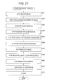
- FIG. 29 is a diagram illustrating an example of a main configuration of a multiple viewpoint image encoding device to which the present technology is applied.
- FIG. 30 is a diagram illustrating an example of a main configuration of a multiple viewpoint image decoding device to which the present technology is applied.
- FIG. 31 is a diagram illustrating an example of a hierarchical image coding system.
- FIG. 32 is a diagram illustrating an example of a main configuration of a hierarchical image encoding device to which the present technology is applied.
- FIG. 33 a diagram illustrating an example of a main configuration of a hierarchical image decoding device to which the present technology is applied.
- FIG. 34 is a block diagram illustrating an example of a main configuration of a computer.
- FIG. 35 is a block diagram illustrating an example a schematic configuration of a television apparatus.
- FIG. 36 is a block diagram illustrating an example of a schematic configuration of a mobile phone.
- FIG. 37 is a block diagram illustrating an example of a schematic configuration of a recording and reproducing device.
- FIG. 38 is a block diagram illustrating an example of a schematic configuration of an imaging device.
- FIG. 39 is a block diagram illustrating an example of scalable encoding utilization.
- FIG. 40 is a block diagram illustrating another example of the scalable encoding utilization.
- FIG. 41 is a block diagram illustrating further another example of the scalable encoding utilization.
- FIG. 42 is a block diagram illustrating an example of a schematic configuration of a video set.
- FIG. 43 is a block diagram illustrating an example of a schematic configuration of a video processor.
- FIG. 44 is a block diagram illustrating another example of a schematic configuration of the video processor.
- FIG. 1 is a block diagram illustrating an example of a main configuration of an image encoding device.
- An image encoding device 100 illustrated in FIG. 1 encodes image data using prediction processing of, for example, high efficiency video coding (HEVC) or a system that is compliant therewith.
- HEVC high efficiency video coding
- the image encoding device 100 includes an A/D converter 101 , a screen rearrangement buffer 102 , a computation unit 103 , an orthogonal transform unit 104 , a quantization unit 105 , a lossless encoding unit 106 , an accumulation buffer 107 , an inverse quantization unit 108 , and an inverse orthogonal transform unit 109 .
- the image encoding device 100 includes a computation unit 110 , a deblocking filter 111 , a frame memory 112 , a selection unit 113 , an intra prediction unit 114 , a motion prediction/compensation unit 115 , a predicted image selection unit 116 , and a rate control unit 117 .
- the image encoding device 100 further includes an orthogonal transform skip unit 121 .
- the A/D converter 101 performs A/D conversion on input image data, supplies the image data (digital data) obtained by the conversion to the screen rearrangement buffer 102 , and stores the image data therein.
- the screen rearrangement buffer 102 rearranges the frame images stored in display order into order of frames for encoding according to a group of picture (GOP) structure and supplies the image, in which order of the frames has been rearranged, to the computation unit 103 .
- the screen rearrangement buffer 102 supplies the image, in which the order of the frames has been rearranged, to the intra prediction unit 114 and the motion prediction/compensation unit 115 .
- the computation unit 103 subtracts a predicted image supplied from the intra prediction unit 114 or the motion prediction/compensation unit 115 through the predicted image selection unit 116 from the image read from the screen rearrangement buffer 102 and outputs difference information to the orthogonal transform unit 104 .
- the computation unit 103 subtracts, from the image read from the screen rearrangement buffer 102 , the predicted image supplied from the intra prediction unit 114 .
- the computation unit 103 subtracts, from the image read from the screen rearrangement buffer 102 , the predicted image supplied from the motion prediction/compensation unit 115 .
- the orthogonal transform unit 104 performs an orthogonal transform such as a discrete cosine transform and a Karhunen-Loeve transform on the difference information supplied from the computation unit 103 and supplies a transform coefficient thereof to the quantization unit 105 .
- an orthogonal transform such as a discrete cosine transform and a Karhunen-Loeve transform
- the quantization unit 105 quantizes the transform coefficient supplied from the orthogonal transform unit 104 .
- the quantization unit 105 sets a quantization parameter based on information on a target value of an encode amount supplied from the rate control unit 117 and performs quantization thereof.
- the quantization unit 105 supplies the quantized transform coefficient to the lossless encoding unit 106 .
- the lossless encoding unit 106 encodes the transform coefficient, which is quantized by the quantization unit 105 , using any coding system. Since coefficient data is quantized under control of the rate control unit 117 , the encode amount thereof is the target value set by the rate control unit 117 (or approximates the target value).
- the lossless encoding unit 106 acquires information indicating a mode of intra prediction and the like from the intra prediction unit 114 and acquires information indicating a mode of inter prediction or difference motion vector information from the motion prediction/compensation unit 115 .
- the lossless encoding unit 106 encodes these various information pieces according to a coding system, to contain (multiplex) the various information pieces as part of header information of coded data (referred also to as a coded stream).
- the lossless encoding unit 106 supplies the coded data obtained by the encoding to the accumulation buffer 107 and accumulates the coded data therein.
- the coding system of the lossless encoding unit 106 includes variable-length encoding or computation encoding.
- the variable-length encoding includes Context-Adaptive Variable Length Coding (CAVLC) and the like defined by the H.264/AVC system.
- the computation encoding includes Context-Adaptive Binary Arithmetic Coding (CABAC) and the like.
- the accumulation buffer 107 temporarily holds the coded data supplied from the lossless encoding unit 106 .
- the accumulation buffer 107 outputs the held coded data to, for example, a recording device (recoding medium) or a transmission path not illustrated in the latter part at predetermined timing. That is, the accumulation buffer 107 is also a transmission unit for transmitting the coded data.
- the quantized transform coefficient by the quantization unit 105 is also supplied to the inverse quantization unit 108 .
- the inverse quantization unit 108 inversely quantizes the quantized transform coefficient by a method corresponding to the quantization by the quantization unit 105 .
- the inverse quantization unit 108 supplies the obtained transform coefficient to the inverse orthogonal transform unit 109 .
- the inverse orthogonal transform unit 109 performs inverse orthogonal transform on the transform coefficient supplied from the inverse quantization unit 108 by a method corresponding to orthogonal transform processing by the orthogonal transform unit 104 .
- An output obtained by the inverse orthogonal transform processing (restored difference information) is supplied to the computation unit 110 .
- the computation unit 110 adds an predicted image supplied from the intra prediction unit 114 or the motion prediction/compensation unit 115 through the predicted image selection unit 116 to the restored difference information which is a result of the inverse orthogonal transform processing supplied from the inverse orthogonal transform unit 109 , thereby obtaining a locally decoded image (decoded image).
- the decoded image is supplied to the deblocking filter 111 or the frame memory 112 .
- the deblocking filter 111 appropriately performs deblocking filter processing on the decoded image supplied from the computation unit 110 .
- the deblocking filter 111 performs the deblocking filter processing on the decoded image to remove block distortion of the decoded image.
- the deblocking filter 111 supplies a result of the filter processing (decoded image after filter processing) to the frame memory 112 . Further, as described above, the decoded image output from the computation unit 110 can be supplied to the frame memory 112 without passing through the deblocking filter 111 . That is, it is possible to omit the filter processing by the deblocking filter 111 .
- the frame memory 112 stores the decoded image to be supplied and supplies the stored decoded image as a reference image to the selection unit 113 at predetermined timing.
- the selection unit 113 selects a supply destination of the reference image supplied from the frame memory 112 .
- the selection unit 113 supplies the reference image supplied from the frame memory 112 to the motion prediction/compensation unit 115 .
- the intra prediction unit 114 performs an intra prediction (in-screen prediction) to generate the predicted image using a pixel value within a current picture which is the reference image supplied from the frame memory 112 through the selection unit 113 .
- the intra prediction unit 114 performs the intra prediction in a plurality of intra prediction modes prepared in advance.
- the intra prediction unit 114 generates the predicted image in all of the intra prediction modes to be candidates and evaluates a cost function value of each predicted image using the input image supplied from the screen rearrangement buffer 102 to select an optimal mode. Upon selecting the optimal intra prediction mode, the intra prediction unit 114 supplies the generated predicted image to the predicted image selection unit 116 in the optimal mode.
- the intra prediction unit 114 appropriately supplies intra prediction mode information indicating an adopted intra prediction mode to the lossless encoding unit 106 to encode the supplied intra prediction mode information.
- the motion prediction/compensation unit 115 performs motion prediction (inter prediction) using the input image supplied from the screen rearrangement buffer 102 and the reference image supplied from the frame memory 112 through the selection unit 113 .
- the motion prediction/compensation unit 115 performs motion compensation processing according to a detected motion vector and generates the predicted image (inter predicted image information).
- the motion prediction/compensation unit 115 performs such an inter prediction in the plurality of inter prediction modes prepared in advance.
- the motion prediction/compensation unit 115 generates the predicted image in all of the inter prediction modes to be candidates.
- the motion prediction/compensation unit 115 evaluates the cost function value of each predicted image using the input image supplied from the screen rearrangement buffer 102 and the information of the generated difference motion vector to select an optimal mode.
- the motion prediction/compensation unit 115 supplies the generated predicted image in the optimal mode to the predicted image selection unit 116 .
- the motion prediction/compensation unit 115 supplies the information indicating an adopted inter prediction mode, information required for performing the processing in the inter prediction mode at the time of decoding the coded data and the like to the lossless encoding unit 106 and encodes the supplied information.
- the required information may include information of the generated difference motion vector, a flag indicating the index of a prediction motion vector as prediction motion vector information, and the like.
- the predicted image selection unit 116 selects a supply source of the predicted image to be supplied to the computation unit 103 or the computation unit 110 .
- the predicted image selection unit 116 selects intra prediction unit 114 as the supply source of the predicted image and supplies the predicted image to be supplied from the intra prediction unit 114 to the computation unit 103 or the computation unit 110 .
- the predicted image selection unit 116 selects the motion prediction/compensation unit 115 as the supply source of the predicted image and supplies the predicted image to be supplied from the motion prediction/compensation unit 115 to the computation unit 103 or the computation unit 110 .
- the rate control unit 117 controls a rate of quantization operation of the quantization unit 105 such that overflow or underflow does not occur.
- the orthogonal transform skip unit 121 controls execution of the orthogonal transform processing in the orthogonal transform unit 104 .
- the orthogonal transform skip unit 121 controls quantization processing by the quantization unit 105 , inverse quantization processing by the inverse quantization unit 108 , inverse orthogonal transform processing by the inverse orthogonal transform unit 109 , and deblocking filter processing by the deblocking filter 111 .
- the orthogonal transform skip unit 121 supplies information necessary on a skip of the orthogonal transform processing and information on the quantization or the deblocking filter to the lossless encoding unit 106 and transmits the supplied information to a decoding side from the accumulation buffer 107 .
- a hierarchical structure including a macroblock and a sub macroblock is specified.
- a macroblock of 16 pixels ⁇ 16 pixels is not most suitable for a large image frame, such as an ultra high definition (UHD; 4000 pixels ⁇ 2000 pixels), that will be the subject of a next-generation coding system.
- UHD ultra high definition
- a coding unit is specified in an HEVC system as illustrated in FIG. 2 .
- the CU is also called a coding tree block (CTB), and is a partial region of an image in a picture unit, which serves the similar role as the macroblock in the AVC system.
- CTB coding tree block
- the latter has a fixed size of 16 ⁇ 16 pixels, whereas the size of the former is not fixed and is thus specified in image compression information in each sequence.
- the maximum size (Largest Coding Unit (LCU)) and the minimum size (Smallest Coding Unit (SCU)) of the CU are specified in a sequence parameter set (Sequence Parameter Set (SPS)) included in the coded data to be output.
- SPS Sequence Parameter Set
- the LCU is 128 ⁇ 128 pixels in size while the maximum hierarchical depth becomes 5.
- the CU having the size of 2N ⁇ 2N pixels is divided into CUs having the size of N ⁇ N pixels that is one level lower in the hierarchy when the value of split_flag is “1”.
- the CU is divided into a prediction unit (PU) that is a region (a partial region of an image in a picture unit) to be a processing unit for the intra prediction or the inter prediction and is also into a transform unit (TU) that is a region (a partial region of an image in a picture unit) to be a processing unit for the orthogonal transform.
- PU prediction unit
- TU transform unit
- the HEVC system can perform 16 ⁇ 16 and 32 ⁇ 32 orthogonal transforms in addition to 4 ⁇ 4 and 8 ⁇ 8 orthogonal transforms.
- the macroblock in the AVC system corresponds to the LCU and a block (sub-block) corresponds to the CU.
- a motion compensation block in the AVC system corresponds to the PU.
- the size of the LCU in the uppermost level thereof is generally set larger than the macroblock in the AVC system, for example, 128 ⁇ 128 pixels.
- the LCU also includes the macroblock in the AVC system and the CU also includes the block (sub-block) in the AVC system.
- the “block” used in the following description indicates any partial region within the picture, and is not limited in the size, shape, characteristics of the block and the like.
- any region (processing unit) for example, TU, PU, SCU, CU, LCU, sub-block, macroblock, or slice is included in the “block”.
- partial regions (processing units) other than these regions are also included therein. The description is appropriately given in the case of limiting the size or the processing unit as necessary.
- the quantization of an orthogonal transform coefficient is performed for every orthogonal transform processing unit in the HEVC.
- a quantization matrix is used for the quantization, but the quantization matrix is prepared for every size of the orthogonal transform processing unit.
- a large quantization matrix such as 16 ⁇ 16 matrix or 32 ⁇ 32 matrix is transmitted, there is a concern that encoding efficiency is reduced.
- the large quantization matrix for example, 16 ⁇ 16 matrix or 32 ⁇ 32 matrix is transmitted in a size of 8 ⁇ 8 and is upsampled by a zero-order hold to be applied to each orthogonal transform size. Further, a DC component is separately transmitted to a matrix to which upsample is applied.
- FIGS. 4 to 7 information on the quantization matrix (Scaling List) is transmitted to a sequence parameter set (SPS) or a picture parameter set (PPS).
- SPS sequence parameter set
- PPS picture parameter set
- FIGS. 4 and 5 are diagrams illustrating examples of the sequence parameter set.
- FIGS. 6 and 7 are diagrams illustrating examples of the picture parameter set.
- the deblocking filter is defined in a motion compensation loop in the HEVC.
- the deblocking filter performs filter processing for reducing block distortion occurring in block boundaries.
- the block boundaries are detected, a type or an strength of the filter, an offset and the like are decided based on quantization parameters or the like at the block boundaries, thereby performing the filter processing.
- JM joint model
- the JM software enables a mode decision method to be selected from two modes of High Complexity Mode and Low Complexity Mode which will be described below.
- a cost function value for every prediction mode ‘Mode’ is calculated, and a prediction mode which minimizes the cost function value is selected as an optimal mode for the block or the macroblock.
- Cost(Mode ⁇ ) D+ ⁇ *R (1)
- ⁇ represents a universal set of candidate modes for encoding the block or the macroblock and “D” represents energy difference between a decoded image and an input image when the encoding is performed in the prediction mode.
- ⁇ represents a Lagrange multiplier given as a function of a quantization parameter.
- R represents a total encode amount including the orthogonal transformation coefficient when the encoding is performed in the mode.
- Cost(Mode ⁇ ) D+QP 2Quant(QP)*HeaderBit (2)
- D represents energy difference between a predicted image and an input image and is different from the High Complexity Mode.
- QP2Quant (QP) is given as a function of a quantization parameter QP
- HeaderBit is an encode amount related to information which belongs to a Header such as a motion vector or a mode, not including the orthogonal transform coefficient.
- the Low Complexity Mode although it is necessary to perform a prediction process for the respective candidate modes, since it is not necessary to obtain a decoded image, it is not necessary to perform the encoding process.
- the low complexity mode can be realized with lower computation amount than the High Complexity Mode.
- An orthogonal transform skip (Transform Skip) is a technique of omitting (skipping) orthogonal transform processing.
- the orthogonal transform processing is performed on image data (differential image data) for every block to convert spatial domain information in the block into frequency domain information, thereby allowing coefficients in the block to be concentrated on a lower frequency, and thus it is possible to increase a bias.
- the encoding efficiency is improved.
- the skipping of the orthogonal transform processing is referred to as an orthogonal transform skip (Transform Skip) in the following description, and a block to which the orthogonal transform skip (Transform Skip) is applied is also referred to as an orthogonal transform skip block.
- a block to which the orthogonal transform skip is not applied (orthogonal transform is performed) is also referred to as a non-orthogonal transform skip block.
- a flag indicating whether the orthogonal transform skip (Transform Skip) can be applied in the sequence is transmitted to the sequence parameter set (SPS).
- This skip enable information (transform_skip_enabled_flag) is set by, for example, a user or the like.
- this value is 1, the orthogonal transform skip (TransformSkip) can be applied to 4 ⁇ 4 luminance orthogonal transform blocks or 4 ⁇ 4 chrominance orthogonal transform blocks.
- an entropy encoding process, quantization processing, loop filter processing and the like are uniformly performed. That is, as on the non-orthogonal transform skip block, the entropy encoding process, the quantization processing, the loop filter processing and the like are also performed on the orthogonal transform skip block.
- the quantization matrix is a weighting coefficient regarding the frequency domain. That is, the quantization matrix is designed to be applied to an orthogonal transform coefficient block. Accordingly, when such a quantization matrix is applied to a block having a spatial domain value (differential image data), the encoding efficiency may be reduced. That is, image quality may be deteriorated.
- the orthogonal transform skip is applied to an image in which the high-frequency component tends to appear. Therefore, there is a high possibility that the content of an image on the orthogonal transform skip block are largely different from those on the non-orthogonal transform skip block. That is, the block distortion easily occurs at the boundary between the orthogonal transform skip block and the non-orthogonal transform skip block.
- the deblocking filter processing when the deblocking filter processing is performed on the boundary between the orthogonal transform skip block and the non-orthogonal transform skip block, the encoding efficiency may be reduced. That is, the image quality may be deteriorated.
- the encoding process is controlled. More specifically, the quantization processing (inverse quantization processing) of the encoding process and the deblocking processing are controlled.
- the quantization processing is performed on the non-orthogonal transform skip block in which the orthogonal transform is performed using a quantization matrix, and the quantization processing is performed on the orthogonal transform skip block in which the orthogonal transform is skipped using one weighting coefficient instead of the quantization matrix. That is, all coefficients of the orthogonal transform skip block serving as the current block are quantized using the one weighting coefficient.
- FIG. 8 A condition thereof is illustrated in FIG. 8 .
- the quantization is performed on the non-orthogonal transform skip block (orthogonal transform coefficient matrix) using quantization matrix as in the prior art.
- the 4 ⁇ 4 orthogonal transform skip block (matrix of pre-orthogonal transform differential value) is quantized using a weighting coefficient matrix which is obtained by the quantization of the one weighting coefficient.
- an actual computation method is arbitrary, but basically performs a computation equivalent to that using the weighting coefficient matrix.
- the weighting coefficient is arbitrary.
- the weighting coefficient may include a scalar value.
- the DC component of the quantization matrix may be the weighting coefficient.
- the quantization matrix is a weighting coefficient regarding the frequency domain, but the DC component is a value regarding the frequency domain and is also a value regarding the spatial domain. If only the DC component of the quantization matrix having these characteristics is present, it is unlikely to lead to reduction of the encoding efficiency even when the quantization is applied to each coefficient of the orthogonal transform skip block which is the value regarding the spatial domain.
- DC components are extracted from the quantization matrix, and the weighting coefficient matrix is generated by rearranging the extracted DC components in 4 ⁇ 4, thereby quantizing the 4 ⁇ 4 orthogonal transform skip block (matrix of pre-orthogonal transform differential value) using the weighting coefficient matrix.
- the weighting coefficient may be arbitrarily generated.
- a method of generating the weighting coefficient is arbitrary.
- the weighting coefficient matrix is generated by rearranging the weighting coefficient in 4 ⁇ 4, thereby quantizing the 4 ⁇ 4 orthogonal transform skip block (matrix of pre-orthogonal transform differential value) using the weighting coefficient matrix.
- a portion to which the orthogonal transform skip block is applied for example, CG image
- the weighting coefficient independent of the quantization matrix as compared to another portion.
- the weighting coefficient may be calculated in the same manner such that a value on a coding side is the same as that on a decoding side and may be transmitted to the decoding side from the coding side.
- the skip enable information (transform_skip_enabled_flag) is transmitted earlier than a quantization matrix (scaling list).
- skip enable information (transform_skip_enabled_flag) is also transmitted to the PPS so that the SPS is independent of the PPS in terms of parsing.
- the SPS is configured as illustrated in FIGS. 9 and 10
- the PPS is configured as illustrated in FIGS. 11 and 12 .
- the weighting coefficient may be generated by a computation of an average value or the like using, for example, the DC component of the quantization matrix which is applied to the quantization of a peripheral block located at the periphery of the current block.
- a computation method is arbitrary and may be other than an average.
- the weighting coefficient matrix is generated by rearranging the weighting coefficient in 4 ⁇ 4, thereby quantizing the 4 ⁇ 4 orthogonal transform skip block (matrix of pre-orthogonal transform differential value) using the weighting coefficient matrix.
- the weighting coefficient is calculated using the quantization matrix of the peripheral block, and thus it is also possible to easily calculate the weighting coefficient on the decoding side in the same manner as on the coding side. That is, the transmission of the weighting coefficient can be omitted, and the encoding efficiency can be improved by that rate.
- a value of boundary strength (bs) acting as block-boundary strength is set to be “+1”.
- bs value By increasing the bs value in this manner, the control is made so as to apply stronger filtering. That is, a stronger deblocking filter can be applied to the boundary between the orthogonal transform skip block and the non-orthogonal transform skip block.
- the bs value may be fixed to a large value of, for example, 2 and the like.
- adjustment of the filter strength is performed from parameters such as the bs value, ⁇ , and ⁇ , but a strong filter may be applied to the boundary between the orthogonal transform skip block and the non-orthogonal transform skip block regardless of the control result of such a filter strength.
- a strong filter may be applied to the boundary between the orthogonal transform skip block and the non-orthogonal transform skip block regardless of the control result of such a filter strength.
- the boundary between the orthogonal transform skip block and the non-orthogonal transform skip block may be set as a smaller offset compared to the ⁇ and tc.
- the deblocking filter it is possible to easily apply the deblocking filter to the boundary between the orthogonal transform skip block and the non-orthogonal transform skip block.
- FIG. 13 is a block diagram illustrating an example of a main configuration of the orthogonal transform skip unit 121 and the like.
- the orthogonal transform skip unit 121 is configured to include a skip encoding unit 131 and a skip determination unit 132 .
- the skip encoding unit 131 acquires the orthogonal transform coefficient and the pre-orthogonal transform differential value of the current block from the orthogonal transform unit 104 when the current block is 4 ⁇ 4 block.
- the skip encoding unit 131 performs the encoding process in the case where the orthogonal transform skip is not applied, using the supplied orthogonal transform coefficient, and generates a cost function value thereof.
- the skip encoding unit 131 performs the encoding process in the case where the orthogonal transform skip is applied, using the supplied pre-orthogonal transform differential value and generates a cost function value thereof.
- the skip encoding unit 131 supplies the cost function values to the skip determination unit 132 .
- the skip encoding unit 131 omits such processing.
- the skip determination unit 132 supplies a control signal which issues an instruction for performing the orthogonal transform, to the orthogonal transform unit 104 .
- the orthogonal transform unit 104 performs the orthogonal transform of the current block based on the control.
- the skip determination unit 132 acquires the skip enable information (transform_skip_enabled_flag) indicating whether or not to enable the skip of the orthogonal transform processing, from the lossless encoding unit 106 .
- This skip enable information (transform_skip_enabled_flag) is set in advance by, for example, a user or the like and is stored in the lossless encoding unit 106 .
- the skip determination unit 132 supplies a control signal for instructing whether or not to enable the orthogonal transform skip corresponding to the skip enable information (transform_skip_enabled_flag) to the orthogonal transform unit 104 .
- the skip determination unit 132 supplies the control signal for enabling the orthogonal transform skip to the orthogonal transform unit 104 .
- the skip enable information indicates that the orthogonal transform skip (for example, the value is 0) is disabled, the skip determination unit 132 supplies the control signal for prohibiting the orthogonal transform skip to the orthogonal transform unit 104 .
- the skip determination unit 132 determines an optimal mode based on the cost function values supplied from the skip encoding unit 131 . That is, it is determined whether or not to apply the orthogonal transform skip (TransformSkip) to the current block.
- the skip determination unit 132 supplies the determined result (information indicating the determined optimal mode) as the control signal to the orthogonal transform unit 104 , the quantization unit 105 , the deblocking filter 111 , the inverse quantization unit 108 , and the inverse orthogonal transform unit 109 .
- the skip determination unit 132 generates skip identification information (TransformSkipFlag) for identifying the determined result (whether the orthogonal transform skip is applied to the current block) and supplies and transmits the skip identification information to the lossless encoding unit 106 .
- skip identification information TransformSkipFlag
- the orthogonal transform unit 104 With respect to the pre-orthogonal transform differential value acquired from the computation unit 103 , the orthogonal transform unit 104 generates the orthogonal transform coefficient and the pre-orthogonal transform differential value of the current block which are not disabled by the control signal supplied from the skip encoding unit 131 in all modes. The orthogonal transform unit 104 supplies the generated the orthogonal transform coefficient and the pre-orthogonal transform differential value of the current block to the skip encoding unit 131 . Further, when the orthogonal transform skip is disabled by the control signal, the orthogonal transform unit 104 supplies only the orthogonal transform coefficient of the current block to the skip encoding unit 131 .
- the orthogonal transform unit 104 acquires the control signal supplied from the skip determination unit 132 and performs processing of the designated mode according to the control. That is, the orthogonal transform unit 104 executes or skips the orthogonal transform processing. In case of executing, the orthogonal transform unit supplies the orthogonal transform coefficient to the quantization unit 105 and in the case of skipping, the pre-orthogonal transform differential value to the quantization unit 105 .
- the orthogonal transform unit 104 can appropriately perform the orthogonal transform as necessary to suppress the reduction of the encoding efficiency, and thus it is possible to suppress the deterioration of the image quality due to encoding/decoding.
- the orthogonal transform unit 104 holds the orthogonal transform coefficient and the pre-orthogonal transform differential value of the current block in all modes to be supplied to the skip encoding unit 131 and, from among the coefficients and values, may select an orthogonal transform coefficient and a pre-orthogonal transform differential value in a mode according to the control signal supplied from the skip determination unit 132 to supply it the quantization unit 105 .
- the control signal supplied from the skip determination unit 132 may select an orthogonal transform coefficient and a pre-orthogonal transform differential value in a mode according to the control signal supplied from the skip determination unit 132 to supply it the quantization unit 105 .
- the quantization unit 105 is configured to include a quantization matrix setting unit 141 , a weighting coefficient generation unit 142 , and a quantization processing unit 143 .
- the quantization matrix setting unit 141 supplies the quantization matrix, which is set by the user or the like, to the weighting coefficient generation unit 142 .
- the weighting coefficient generation unit 142 acquires the control signal supplied from the skip determination unit 132 .
- the weighting coefficient generation unit 142 supplies the quantization matrix or the weighting coefficient to the quantization processing unit 143 based on the control of the control signal.
- the weighting coefficient generation unit 142 supplies the quantization matrix, which is supplied from the quantization matrix setting unit 141 in the mode designated by the control signal, to the quantization processing unit 143 .
- the weighting coefficient generation unit 142 when the orthogonal transform skip is applied, the weighting coefficient generation unit 142 generates the weighting coefficient and supplies the generated weighting coefficient to the quantization processing unit 143 .
- a method of generating the weighting coefficient is arbitrary.
- a DC component extracted from the quantization matrix supplied from the quantization matrix setting unit 141 may be set as the weighting coefficient, apart from the quantization matrix supplied from the quantization matrix setting unit 141 , another weighting coefficient may be set, and the weighting coefficient may be calculated from the DC component of the quantization matrix of the peripheral block.
- the quantization processing unit 143 quantizes the orthogonal transform coefficient or the pre-orthogonal transform differential value supplied from the orthogonal transform unit 104 using the quantization matrix or the weighting coefficient supplied from the weighting coefficient generation unit 142 and the quantization parameter or the like supplied from the rate control unit 117 .
- the quantization processing unit 143 quantizes the orthogonal transform coefficient of the current block using the quantization matrix, the quantization parameter or the like when the orthogonal transform coefficient is supplied from the orthogonal transform unit 104 .
- the quantization processing unit 143 quantizes the pre-orthogonal transform differential value of the current block using the weighting coefficient, the quantization parameter or the like when the pre-orthogonal transform differential value is supplied from the orthogonal transform unit 104 .
- the quantization processing unit 143 supplies the quantized coefficient to the lossless encoding unit 106 and the inverse quantization unit 108 .
- the quantization processing unit 143 supplies and transmits a parameter regarding the quantization of, for example, the weighting coefficient or the like to the lossless encoding unit 106 , when necessary.
- the quantization processing unit 143 can appropriately perform the quantization so as to suppress the deterioration of the image quality. Accordingly, the image encoding device 100 can suppress the deterioration of the image quality due to the encoding/decoding. In other words, the image encoding device 100 can improve the encoding efficiency.
- the quantization processing unit 143 may supply the quantization matrix or the weighting coefficient applied to the quantization processing together with, for example, the quantized coefficient to the inverse quantization unit 108 .
- the deblocking filter 111 is configured to include a boundary determination unit 151 , a strength adjustment unit 152 , and a filtering unit 153 .
- the boundary determination unit 151 acquires the control signal supplied from the skip determination unit 132 , with respect to the current block. Further, the boundary determination unit 151 acquires skip identification information (TransformSkipFlag) for identifying whether the orthogonal transform skip is applied to the peripheral block of the current block (TransformSkipFlag). The boundary determination unit 151 determines whether a current block boundary is the boundary between the orthogonal transform skip block and the non-orthogonal transform skip block, based on such information, and supplies a control signal indicating the determined result to the strength adjustment unit 152 .
- skip identification information TransformSkipFlag
- the strength adjustment unit 152 generates various parameters such as Bs value, ⁇ , ⁇ , and tc and determines strength of the deblocking filter based on these values and the control signal supplied from the boundary determination unit 151 . That is, the strength adjustment unit 152 determines the strength of the deblocking filter based on values of various parameters such as the generated Bs value, ⁇ , ⁇ , and tc when the current block boundary is not the boundary between the orthogonal transform skip block and the non-orthogonal transform skip block. In addition, when the current block boundary is the boundary between the orthogonal transform skip block and the non-orthogonal transform skip block, the strength adjustment unit 152 further makes filter strength strong based on the control signal in any manner as described above, for example.
- the strength adjustment unit 152 notifies the filtering unit 153 of the set filter strength.
- the filtering unit 153 performs the deblocking filter processing on a pre-deblocking filter pixel value of the block boundary supplied from the computation unit 110 with the filter strength supplied from the strength adjustment unit 152 .
- the filtering unit 153 supplies a post-deblocking filter pixel value to the frame memory 112 to store it therein. This information is used intra or inter prediction processing.
- the deblocking filter 111 can perform the filter processing on the boundary between the orthogonal transform skip block and the non-orthogonal transform skip block such that the stronger deblocking filter is applied. Accordingly, the deterioration of the image quality is further suppressed. That is, the image encoding device 100 can suppress the deterioration of the image quality due to the encoding/decoding. In other words, the image encoding device 100 can improve the encoding efficiency.
- step S 101 the lossless encoding unit 106 generates the skip enable information (transform_skip_enabled_flag) indicating whether or not to enable the skip of the orthogonal transform processing, based on the user's instruction or the like, for example.
- the skip enable information (transform_skip_enabled_flag) is transmitted to the SPS.
- step S 102 the A/D converter 101 performs A/D conversion on an input image.
- step S 103 the screen rearrangement buffer 102 stores the image obtained by the A/D conversion and rearranges respective pictures from a display order to an encoding order.
- step S 104 the intra prediction unit 114 performs intra prediction processing in the intra prediction mode.
- step S 105 the motion prediction/compensation unit 115 performs inter motion prediction processing, in which the motion prediction or the motion compensation is performed in the inter prediction mode.
- step S 106 the predicted image selection unit 116 determines an optimal mode based on each of the cost function values output from the intra prediction unit 114 and the motion prediction/compensation unit 115 . That is, the predicted image selection unit 116 selects either one of a predicted image generated by the intra prediction unit 114 and a predicted image generated by the motion prediction/compensation unit 115 .
- step S 107 the computation unit 103 computes a difference between the rearranged image obtained by the processing in step S 103 and the predicted image selected by the processing in step S 106 .
- the difference data is reduced in the data amount as compared to original image data. Accordingly, the data amount can be compressed as compared to a case in which images are directly encoded.
- step S 108 the orthogonal transform skip unit 121 performs orthogonal transform skip control processing.
- step S 109 the orthogonal transform unit 104 performs orthogonal transform processing on the difference information generated by the processing in step S 107 according to the processing result in step S 108 .
- step S 110 the quantization unit 105 quantizes the orthogonal transform coefficient or the pre-orthogonal transform differential value obtained by the processing in step S 109 , using the quantization parameter supplied from the rate control unit 117 , according to the processing result in step S 108 .
- the difference information quantized by the processing in step S 110 is locally decoded as follows. That is, in step S 111 , the inverse quantization unit 108 performs inverse quantization on the quantized coefficient (also referred to as a quantization coefficient) generated by the processing in step S 111 with characteristics corresponding to those of the quantization unit 105 , according to the processing result in step S 108 . In step S 112 , the inverse orthogonal transform unit 109 performs inverse orthogonal transform on the orthogonal transform coefficient or the pre-orthogonal transform differential value obtained by the processing in step S 111 according to the processing result in step S 108 .
- the quantized coefficient also referred to as a quantization coefficient
- step S 111 and step S 112 corresponds to that of a similar processing operation to be executed in the decoding process, the detailed description thereof will be not presented.
- step S 113 the computation unit 110 adds the predicted image to the locally decoded difference information to generate a locally decoded image (an image corresponding to that input to the computation unit 103 ).
- step S 114 the deblocking filter 111 appropriately performs the deblocking filter processing on the locally decoded image obtained by the processing in step S 113 , according to the processing result in step S 108 .
- step S 115 the frame memory 112 stores the decoded image subjected to the deblocking filter processing by the processing in step S 114 . Further, images that are not subjected to the filtering by the deblocking filter 111 are also supplied from the computation unit 110 and stored in the frame memory 112 .
- step S 116 the lossless encoding unit 106 encodes the quantized coefficient by the processing in step S 110 . That is, lossless encoding such as variable-length encoding or computation encoding is performed on data corresponding to the difference image.
- the lossless encoding unit 106 encodes information on a prediction mode of the predicted image selected by the processing in step S 106 and adds the encoded information to the coded data obtained by encoding the difference image. That is, the lossless encoding unit 106 also encodes information such as optimal intra prediction mode information supplied from the intra prediction unit 114 or information according to the optimal inter prediction mode supplied from the motion prediction/compensation unit 115 and adds the encoded information to the coded data.
- the lossless encoding unit 106 appropriately further encodes information on the orthogonal transform or the quantization and the encoded information to the coded data.
- step S 117 the accumulation buffer 107 accumulates the coded data obtained by the processing in step S 116 .
- the coded data accumulated in the accumulation buffer 107 is appropriately read out and transmitted to a decoding side through a transmission path or a recording medium.
- step S 118 the rate control unit 117 controls the rate of quantization operation of the quantization unit 105 so as not to cause overflow or underflow based on the encode amount (generated encode amount) of the coded data accumulated in the accumulation buffer 107 by the processing in step S 117 .
- the rate control unit 117 supplies information on the quantization parameter to the quantization unit 105 .
- the encoding process is completed when the processing in step S 118 is ended.
- the skip determination unit 132 determines in step S 131 whether or not to enable a TransformSkip mode in which the orthogonal transform skip is performed, based on the skip enable information (transform_skip_enabled_flag).
- step S 132 the skip determination unit 132 allows the TransformSkip mode to be included in a candidate mode.
- step S 134 the processing proceeds to step S 134 .
- step S 132 when it is determined in step S 132 that the TransformSkip mode is not enabled, the processing proceeds to step S 133 .
- step S 133 the skip determination unit 132 eliminates the TransformSkip mode from the candidate mode.
- step S 134 the processing proceeds to step S 134 .
- step S 134 the skip encoding unit 131 selects an unprocessed candidate mode.
- step S 135 the skip encoding unit 131 determines whether the selected mode is the orthogonal transform (TransformSkip) mode.
- step S 136 the skip encoding unit 131 generates a weighting coefficient.
- step S 139 the processing proceeds to step S 139 .
- step S 135 When it is determined that the selected mode is not the orthogonal transform (TransformSkip) mode in step S 135 , the processing proceeds to step S 137 .
- step S 137 the skip encoding unit 131 performs the orthogonal transform on the current block.
- step S 138 the skip encoding unit 131 acquires a quantization matrix.
- step S 139 the skip encoding unit 131 performs an encoding operation using the orthogonal transform coefficient obtained by the orthogonal transform unit 104 or the pre-orthogonal transform differential value and generates a cost function value with respect to the current mode.
- step S 140 the skip encoding unit 131 determines whether all of the candidate modes are processed. When an unprocessed candidate mode exists, the processing returns to step S 134 and subsequent processing operations are repeatedly executed. That is, each processing operation in step S 134 to step S 140 is repeatedly executed until the cost function value is generated with respect to all of the modes.
- step S 140 When it is determined in step S 140 that all of the candidate modes are processed, the processing proceeds to step S 141 .
- step S 141 the skip determination unit 132 determines the optimal mode based on the cost function value.
- step S 142 the skip determination unit 132 generates skip identification information (TransformSkipFlag) based on the optimal mode.
- step S 142 When the processing in step S 142 is ended, the orthogonal transform skip control processing is completed, and the processing returns to the processing operation illustrated in FIG. 14 .
- the orthogonal transform unit 104 determines in step S 151 whether the optimal mode selected by the skip determination unit 132 is the orthogonal transform skip (TransformSkip mode). When it is determined to be the orthogonal transform skip (TransformSkip mode), the processing proceeds to step S 152 .
- step S 152 the orthogonal transform unit 104 skips the orthogonal transform processing and outputs the pre-orthogonal transform differential value of the current block.
- the processing in step S 152 is ended, the processing returns to the process illustrated in FIG. 14 .
- step S 151 of FIG. 16 when it is determined not to be the orthogonal transform skip (TransformSkip mode), the processing proceeds to step S 153 .
- step S 153 the orthogonal transform unit 104 performs the orthogonal transform on the pre-orthogonal transform differential value of the current block.
- step S 154 the orthogonal transform unit 104 outputs the obtained orthogonal transform coefficient.
- the weighting coefficient generation unit 142 determines, in step S 161 , whether the optimal mode selected by the skip determination unit 132 is the orthogonal transform skip (TransformSkip mode). When it is determined to be the orthogonal transform skip (TransformSkip mode), the processing proceeds to step S 162 .
- step S 162 the weighting coefficient generation unit 142 generates a weighting coefficient.
- step S 162 the processing proceeds to step S 164 .
- step S 161 when it is determined not to be the orthogonal transform skip (TransformSkip mode) in step S 161 , the processing proceeds to step S 163 .
- step S 163 the weighting coefficient generation unit 142 acquires a quantization matrix.
- step S 163 the processing proceeds to step S 164 .
- step S 164 the quantization processing unit 143 performs the quantization of the orthogonal transform coefficient of the current block or the pre-orthogonal transform coefficient differential value using the weighting coefficient generated in step S 162 and the quantization matrix acquired in step S 163 .
- step S 165 the quantization processing unit 143 supplies and transmits the quantization matrix and the applied weighting coefficient to the lossless encoding unit 106 .
- the processing in step S 165 is ended, the quantization processing is completed, and the processing returns to the process illustrated in FIG. 14 .
- the strength adjustment unit 152 acquires mode information, motion vector, reference frame information or the like in step S 171 .
- step S 172 the strength adjustment unit 152 detects block boundaries of the TU, PU or the like.
- step S 173 the strength adjustment unit 152 determines a Bs value based on such information.
- step S 174 the strength adjustment unit 152 calculates a quantization parameter (boundary QP) in the block boundary by defining quantization parameters of both blocks as QP_P and QP_Q, as in Formula (3) below.
- QP (QP_P+QP_Q+1)>>1 (3)
- step S 175 the strength adjustment unit 152 determines a ⁇ offset value and a tc offset value using the boundary QP calculated as described above.
- step S 176 the strength adjustment unit 152 determines filters (strong, weak, and off) by processing the calculated offset values.
- step S 177 the boundary determination unit 151 acquires a control signal of the current block from the skip determination unit 132 and acquires skip identification information (TransformSkipFlag) of the peripheral block from the lossless encoding unit 106 .
- skip identification information TransformSkipFlag
- step S 178 the boundary determination unit 151 determines whether the current block boundary is the boundary between the orthogonal transform skip block and the non-orthogonal transform skip block.
- step S 179 the strength adjustment unit 152 adjusts the strength of the deblocking filter.
- step S 180 the processing proceeds to step S 180 .
- step S 178 when it is determined in step S 178 that the current block boundary is not the boundary between the orthogonal transform skip block and the non-orthogonal transform skip block, the processing proceeds to step S 180 .
- step S 180 the filtering unit 153 performs the deblocking filter processing.
- the deblocking filter processing is completed, and the processing returns to the process illustrated in FIG. 14 .
- the image encoding device 100 can suppress the reduction of the encoding efficiency and suppress the deterioration of the image quality due to the encoding/decoding.
- FIG. 19 is a block diagram illustrating an example of a main configuration of an image decoding device corresponding to the image encoding device 100 in FIG. 1 .
- An image decoding device 200 illustrated in FIG. 19 decodes the coded data generated by the image encoding device 100 , using a decoding method corresponding to the coding system thereof.
- the image decoding device 200 includes an accumulation buffer 201 , a lossless decoding unit 202 , an inverse quantization unit 203 , an inverse orthogonal transform unit 204 , a computation unit 205 , a deblocking filter 206 , a screen rearrangement buffer 207 , and a D/A converter 208 .
- the image decoding device 200 includes a frame memory 209 , a selection unit 210 , an intra prediction unit 211 , a motion prediction/compensation unit 212 , and a selection unit 213 .
- the image decoding device 200 includes an inverse orthogonal transform skip unit 221 .
- the accumulation buffer 201 is also a reception unit for receiving the coded data transmitted thereto.
- the accumulation buffer 201 receives and accumulates the coded data transmitted therein, and supplies the coded data to the lossless decoding unit 202 at a predetermining timing. Pieces of information necessary for decoding, such as the prediction mode information, are added to the coded data.
- the lossless decoding unit 202 decodes the information, which is supplied from the accumulation buffer 201 and encoded by the lossless encoding unit 106 in FIG. 1 , using a method corresponding to the coding system of the lossless encoding unit 106 .
- the lossless decoding unit 202 supplies the quantized coefficient data of a difference image obtained by decoding to the inverse quantization unit 203 .
- the lossless decoding unit 202 determines whether the intra prediction mode is selected or the inter prediction mode is selected, as the optimal prediction mode, and supplies information relating to the optimal prediction mode to one of the intra prediction unit 211 and the motion prediction/compensation unit 212 , which is a mode determined to be selected.
- the information relating to the optimal prediction mode is supplied to the intra prediction unit 211 .
- the information regarding the optimal prediction mode is supplied to the motion prediction/compensation unit 212 .
- the lossless decoding unit 202 supplies information such as, for example, a quantization matrix or a quantization parameter, which is required for inverse quantization, to the inverse quantization unit 203 . Further, the lossless decoding unit 202 supplies information such as, for example, skip enable information (transform_skip_enabled_flag) or skip identification information (TransformSkipFlag), which is required for an inverse orthogonal transform, to the inverse orthogonal transform skip unit 221 .
- skip enable information transform_skip_enabled_flag
- TransformSkipFlag skip identification information
- the inverse quantization unit 203 performs inverse quantization on the quantized coefficient data obtained by decoding of the lossless decoding unit 202 based on the control of the inverse orthogonal transform skip unit 221 , using a method corresponding to the quantization method of the quantization unit 105 in FIG. 1 .
- the inverse quantization unit 203 is a processing unit similar to the inverse quantization unit 108 of the image encoding device 100 in FIG. 1 . That is, the description of the inverse quantization unit 203 can be also applied to that of the inverse quantization unit 108 . However, it is necessary to read input/output destination of data by appropriately varying it depending on devices.
- the inverse quantization unit 203 supplies the obtained coefficient data to the inverse orthogonal transform unit 204 .
- the inverse orthogonal transform unit 204 Based on the control of the inverse orthogonal transform skip unit 221 , the inverse orthogonal transform unit 204 performs inverse orthogonal transform of the coefficient data (orthogonal transform coefficient or pre-orthogonal transform differential value) to be supplied from the inverse quantization unit 203 using a method corresponding to the orthogonal transform method of the orthogonal transform unit 104 in FIG. 1 , as necessary. Further, the inverse orthogonal transform unit 204 is a processing unit similar to the inverse orthogonal transform unit 109 of the image encoding device 100 in FIG. 1 . That is, the description of the inverse orthogonal transform unit 204 can be also applied to that of the inverse orthogonal transform unit 109 . However, it is necessary to read input/output destination of data by appropriately varying it depending on devices.
- the inverse orthogonal transform unit 204 obtains decoded residual data corresponding to the residual data before the orthogonal transform by the inverse orthogonal transform processing in the image encoding device 100 .
- the decoded residual data obtained by the inverse orthogonal transform is supplied to the computation unit 205 .
- a predicted image is supplied to the computation unit 205 through the selection unit 213 from the intra prediction unit 211 or the motion prediction/compensation unit 212 .
- the computation unit 205 adds the decoded residual data and the predicted image and obtains decoded image data corresponding to image data before the predicted image is subtracted by the computation unit 103 of the image encoding device 100 .
- the computation unit 205 supplies the decoded image data to the deblocking filter 206 .
- the deblocking filter 206 appropriately performs deblocking filter processing on the supplied decoded image and supplies it to the screen rearrangement buffer 207 .
- the deblocking filter 206 removes the block distortion of the decoded image.
- the deblocking filter 206 is a processing unit similar to the deblocking filter 111 of the image encoding device 100 in FIG. 1 .
- the deblocking filter 206 supplies a filter processing result (a decoded image after filter processing) to the screen rearrangement buffer 207 and the frame memory 209 .
- the decoded image output from the computation unit 205 may be supplied to the screen rearrangement buffer 207 or the frame memory 209 without passing through the deblocking filter 206 .
- the filter processing performed by the deblocking filter 206 may be omitted.
- the screen rearrangement buffer 207 rearranges images. In other words, the order of the frames rearranged for the encoding order by the screen rearrangement buffer 102 in FIG. 1 is rearranged in the original display order.
- the D/A converter 208 D/A-converts the image supplied from the screen rearrangement buffer 207 and outputs the image to a display not illustrated in the drawing to display the image thereon.
- the frame memory 209 stores therein the supplied decoded image and supplies the stored decoded image, as a reference image, to the selection unit 210 , at a predetermined timing or on the basis of a request from the outside, such as the intra prediction unit 211 or the motion prediction/compensation unit 212 .
- the selection unit 210 selects the supply destination of the reference image supplied from the frame memory 209 .
- the selection unit 210 supplies the reference image supplied from the frame memory 209 to the intra prediction unit 211 .
- the selection unit 210 supplies the reference image supplied from the frame memory 209 to the motion prediction/compensation unit 212 .
- the intra prediction unit 211 To the intra prediction unit 211 is supplied information or the like indicating the intra prediction mode, which is obtained by decoding header information, appropriately from the lossless decoding unit 202 .
- the intra prediction unit 211 performs intra prediction using the reference image acquired from the frame memory 209 , in the intra prediction mode used in the intra prediction unit 114 in FIG. 1 , and generates a predicted image.
- the intra prediction unit 211 supplies the generated predicted image to the selection unit 213 .
- the motion prediction/compensation unit 212 acquires information (the optimal prediction mode information, the reference image information, and so forth), which is obtained by decoding the header information, from the lossless decoding unit 202 .
- the motion prediction/compensation unit 212 performs inter prediction using the reference image acquired from the frame memory 209 , in the inter prediction mode indicated by the optimal prediction mode information acquired from the lossless decoding unit 202 , and generates a predicted image.
- the selection unit 213 supplies the predicted image from the intra prediction unit 211 or the predicted image from the motion prediction/compensation unit 212 to the computation unit 205 .
- the predicted image generated using the motion vector and the decoded residual data (difference image information) from the inverse orthogonal transform unit 204 are added, and an original image is decoded.
- the motion prediction/compensation unit 212 , the lossless decoding unit 202 , the inverse quantization unit 203 , the inverse orthogonal transform unit 204 , and the computation unit 205 are also a decoding unit for decoding the coded data using the motion vector and generating the original image.
- the inverse orthogonal transform skip unit 221 acquires the information supplied from the coding side through the lossless decoding unit 202 and controls execution of the inverse orthogonal transform processing in the inverse orthogonal transform unit 204 based on the information. In addition, the inverse orthogonal transform skip unit 221 controls the inverse quantization processing by the inverse quantization unit 203 and the deblocking filter processing by the deblocking filter 206 .
- the image decoding device 200 can appropriately decode the coded data. Accordingly, the image decoding device 200 can realize the suppression of the reduction in the encoding efficiency and can realize the suppression of the deterioration of the image quality dude to the encoding/decoding.
- FIG. 20 is a block diagram illustrating an example of a main configuration of the inverse orthogonal transform skip unit 221 or the like.
- the inverse orthogonal transform skip unit 221 is configured to include a TransfomSkipFlag buffer 231 and a control signal generation unit 232 .
- the TransfomSkipFlag buffer 231 acquires and holds the skip enable information (transform_skip_enabled_flag) or the skip identification information (TransfomSkipFlag) extracted from the coded data (bit stream) in the lossless decoding unit 202 .
- the TransfomSkipFlag buffer 231 supplies the held the skip enable information (transform_skip_enabled_flag) or the skip identification information (TransfomSkipFlag) to the control signal generation unit 232 at predetermined timing or based on a demand.
- the control signal generation unit 232 generates a control signal depending on the skip enable information (transform_skip_enabled_flag) or the skip identification information (TransfomSkipFlag) supplied from the TransfomSkipFlag buffer 231 and supplies the control signal to the inverse quantization unit 203 , the inverse orthogonal transform unit 204 , and the deblocking filter 206 .
- the control signal generation unit 232 supplies a control signal as follows. That is, the control signal generation unit 232 supplies a control signal for instructing the inverse quantization unit 203 to perform the inverse quantization using the quantization matrix. In addition, the control signal generation unit 232 supplies a control signal for instructing the inverse orthogonal transform unit 204 to perform the inverse orthogonal transform. Further, the control signal generation unit 232 supplies a control signal for notifying the deblocking filter 206 that the current block is not the orthogonal transform skip block.
- the control signal generation unit 232 supplies the control signal in following manners. That is, the control signal generation unit 232 supplies the control signal for instructing the inverse quantization unit 203 to perform the inverse quantization using the quantization matrix. In addition, the control signal generation unit 232 supplies the control signal instructing the inverse orthogonal transform unit 204 to perform the inverse orthogonal transform.
- control signal generation unit 232 supplies the control signal for notifying the deblocking filter 206 that the current block is not the orthogonal transform skip block. That is, the control signal generation unit 232 may supply the skip identification information (TransfomSkipFlag) as the control signal to the deblocking filter 206 .
- skip identification information TransfomSkipFlag
- the control signal generation unit 232 supplies the control signal in the following manners. That is, the control signal generation unit 232 supplies a control signal for instructing the inverse quantization unit 203 to perform the inverse quantization using the weighting coefficient. In addition, the control signal generation unit 232 supplies a control signal instructing for the inverse orthogonal transform unit 204 not to perform the inverse orthogonal transform.
- control signal generation unit 232 supplies a control signal for notifying the deblocking filter 206 that the current block is the orthogonal transform skip block. That is, the control signal generation unit 232 may supply the skip identification information (TransfomSkipFlag) as the control signal to the deblocking filter 206 .
- skip identification information TransfomSkipFlag
- the inverse quantization unit 203 is configured to include a quantization matrix buffer 241 , a weighting coefficient generation unit 242 , a quantization parameter buffer 243 , and an inverse quantization unit 244 .
- the quantization matrix buffer 241 acquires and holds the quantization matrix, which is extracted from the SPS or the like of the coded data, by the lossless decoding unit 202 .
- the quantization matrix is transmitted from the coding side and is used at the time of encoding.
- the quantization matrix buffer 241 supplies the held quantization matrix to the weighting coefficient generation unit 242 at predetermined timing or on demand. Further, when the weighting coefficient applied at the time of encoding is transmitted from the coding side, the quantization matrix buffer 241 acquires the weighting coefficient and supplies it to the weighting coefficient generation unit 242 as in the quantization matrix.
- the weighting coefficient generation unit 242 acquires the control signal supplied from the control signal generation unit 232 .
- the weighting coefficient generation unit 242 grasps whether the orthogonal transform skip is applied to the current block at the time of encoding, based on the control of the control signal and supplies the quantization matrix or the weighting coefficient to the inverse quantization unit 244 based on the grasped information.
- the weighting coefficient generation unit 242 supplies the quantization matrix, which is supplied from the quantization matrix buffer 241 , of a mode designated by the control signal to the inverse quantization unit 244 .
- the weighting coefficient generation unit 242 when the orthogonal transform skip is applied to the current block at the time of encoding, the weighting coefficient generation unit 242 generates a weighting coefficient and supplies the generated weighting coefficient to the inverse quantization unit 244 .
- a method of generating the weighting coefficient is arbitrary as long as the method is the same as a method in the coding side. That is, for example, in the image encoding device 100 , when the weighting coefficient generation unit 142 extracts the DC component of the quantization matrix supplied from the quantization matrix setting unit 141 and sets the extracted DC component as a weighting coefficient, the weighting coefficient generation unit 242 , similarly, also extracts the DC component of the quantization matrix supplied from the quantization matrix buffer 241 and also sets the extracted DC component as a weighting coefficient.
- the weighting coefficient generation unit 242 when the weighting coefficient generation unit 142 sets a weighting coefficient separated from the quantization matrix supplied from the quantization matrix setting unit 141 , the weighting coefficient generation unit 242 also sets a weighting coefficient separated from the quantization matrix supplied from the quantization matrix buffer 241 in the same way. At this time, when the weighting coefficient applied at the time of encoding is supplied from the coding side, the weighting coefficient is applied.
- the weighting coefficient generation unit 242 when the weighting coefficient generation unit 142 calculates the weighting coefficient from the DC component of the quantization matrix of the peripheral block, the weighting coefficient generation unit 242 also calculates the weighting coefficient from the DC component of the quantization matrix of the peripheral block in the same way.
- the quantization parameter buffer 243 acquires and holds the quantization parameter extracted from the SPS or the like of the coded data by the lossless decoding unit 202 .
- the quantization parameter is supplied from the coding side and is used at the time of encoding.
- the quantization parameter buffer 243 supplies the held quantization parameter to the inverse quantization unit 244 at predetermined timing or on demand.
- the inverse quantization unit 244 acquires the quantized coefficient extracted from the coded data by the lossless decoding unit 202 .
- the inverse quantization unit 244 also acquires the quantization parameter from the quantization parameter buffer 243 and acquires the quantization matrix or the weighting coefficient from the weighting coefficient generation unit 242 .
- the inverse quantization unit 244 inversely quantizes the quantized coefficient using them. This method of inverse quantization corresponds to the method of quantization by the quantization processing unit 143 of the image encoding device 100 .
- the inverse quantization unit inversely quantizes the quantized coefficient using the quantization matrix and the quantization parameter and supplies the obtained orthogonal transform coefficient to the inverse orthogonal transform unit 204 .
- the inverse quantization unit inversely quantizes the quantized coefficient using the weighting coefficient and the quantization parameter and supplies the obtained pre-orthogonal transform differential value to the inverse orthogonal transform unit 204 .
- the inverse quantization unit 203 can appropriately perform the inverse quantization using a method corresponding to the quantization at the time of encoding. That is, the inverse quantization unit 203 can appropriately quantize the quantized coefficient by the quantization unit 105 of the image encoding device 100 . Accordingly, the inverse quantization unit 203 can appropriately perform the inverse quantization so as to suppress the deterioration of the image quality. Therefore, the image decoding device 200 can realize the suppression of the deterioration of the image quality due to the encoding/decoding. In other words, the image decoding device 200 can improve the encoding efficiency.
- the inverse orthogonal transform unit 204 appropriately performs the inverse orthogonal transform on the inversely quantized coefficient supplied from the inverse quantization unit 244 based on the control signal supplied from the control signal generation unit 232 .
- the inverse orthogonal transform unit 204 grasps based on the control signal that the inversely quantized coefficient supplied from the inverse quantization unit 244 is the orthogonal transform coefficient. That is, the inverse orthogonal transform unit 204 performs the inverse orthogonal transform on the orthogonal transform coefficient in a method that corresponds to the orthogonal transform of the orthogonal transform unit 104 in the image encoding device 100 .
- the inversely quantized coefficient serving as a value of the frequency domain is converted into the pre-orthogonal transform differential value (decoded residual data) serving as a value of the spatial domain.
- the inverse orthogonal transform unit 204 supplies the decoded residual data to the computation unit 205 .
- the inverse orthogonal transform unit 204 grasps based on the control signal that the inversely quantized coefficient supplied from the inverse quantization unit 244 is the pre-orthogonal transform differential value.
- the inverse orthogonal transform unit 204 supplies the pre-orthogonal transform differential value serving as the value of the spatial domain to the computation unit 205 , as the decoded residual data.
- the inverse orthogonal transform unit 204 can appropriately perform the inverse orthogonal transform in the method that corresponds to the orthogonal transform at the time of encoding. That is, for example, the inverse orthogonal transform unit 204 can perform appropriate processing on the coefficient generated by the orthogonal transform unit 104 of the image encoding device 100 . Accordingly, the inverse orthogonal transform unit 204 can appropriately perform the inverse orthogonal transform so as to suppress the deterioration of the image quality. Therefore, the image decoding device 200 can realize the suppression of the deterioration of the image quality due to the encoding/decoding. In other words, the image decoding device 200 can improve the encoding efficiency.
- the deblocking filter 206 is configured to include a boundary determination unit 251 , a strength adjustment unit 252 , and a filtering unit 253 .
- the boundary determination unit 251 is a processing unit similar to the boundary determination unit 151 of the image encoding device 100 .
- the control signal for example, skip identification information (TransformSkipFlag)
- the boundary determination unit 251 holds such information, determines whether the current block boundary is the boundary between the orthogonal transform skip block and the non-orthogonal transform skip block, and supplies the control signal indicating the determined result to the strength adjustment unit 252 .
- the strength adjustment unit 252 is a processing unit similar to the strength adjustment unit 152 of the image encoding device 100 .
- the strength adjustment unit 252 generates various parameters such as a Bs value, ⁇ , ⁇ , and tc and determines the strength of the deblocking filter based on such values and the control signal supplied from the boundary determination unit 251 . That is, the strength adjustment unit 252 determines the strength of the deblocking filter based on various parameters such as the generated Bs value, ⁇ , ⁇ , and tc when the current block boundary is not the boundary between the orthogonal transform skip block and the non-orthogonal transform skip block.
- the strength adjustment unit 252 additionally strengthens the filter strength based on the control signal, for example, in any manner similar to the above manner when the current block boundary is the boundary between the orthogonal transform skip block and the non-orthogonal transform skip block.
- the same method as in the strength adjustment unit 152 is used for the determination and adjustment of the filter strength. That is, the filter strength applied at the time of encoding is reproduced.
- the strength adjustment unit 252 notifies the filtering unit 253 of the filter strength which is set in this manner.
- the filtering unit 253 is a processing unit similar to the filtering unit 253 of the image encoding device 100 .
- the filtering unit 253 performs the deblocking filter processing on the decoded residual data (pre-deblocking filter pixel value) of the block boundary which is supplied from the computation unit 205 , using the filter strength supplied from the strength adjustment unit 252 .
- the filtering unit 253 supplies a post-deblocking filter pixel value, which is obtained by performing the deblocking filter processing, to the screen rearrangement buffer 207 or the frame memory 209 .
- the deblocking filter 206 can perform the filter processing on the boundary between the orthogonal transform skip block and the non-orthogonal transform skip block such that the stronger deblocking filter is applied. Accordingly, the deterioration of the image quality is further suppressed. That is, the image decoding device 200 can achieve the suppression of the deterioration of the image quality due to the encoding/decoding. In other words, the image decoding device 200 can achieve the improvement of the encoding efficiency.
- the accumulation buffer 201 accumulates the transmitted coded data in step S 201 .
- the lossless decoding unit 202 decodes the bit stream (encoded differential image information) supplied from the accumulation buffer 201 . That is, I-pictures, P-pictures, and B-pictures which are encoded by the lossless encoding unit 106 illustrated in FIG. 1 are decoded.
- step S 203 the TransformSkipFlag buffer 231 of the inverse orthogonal transform skip unit 221 acquires the skip identification information (TransformSkipFlag) extracted in the lossless decoding unit 202 .
- the control signal generation unit 232 of the inverse orthogonal transform skip unit 221 generates a control signal based on the skip identification information (TransformSkipFlag) and supplies the control signal to the weighting coefficient generation unit 242 , the inverse orthogonal transform unit 204 , and the boundary determination unit 251 .
- step S 204 the inverse quantization unit 203 inversely quantizes a quantized coefficient obtained by the processing operation of step S 202 .
- step S 205 the inverse orthogonal transform unit 204 performs an inverse orthogonal transform on the inversely-quantized coefficient obtained in step S 204 as necessary.
- step S 206 the intra prediction unit 211 or the motion prediction/compensation unit 212 performs a prediction processing operation and generates a predicted image. That is, the prediction processing operation is performed in the prediction mode which is determined by lossless decoding unit 202 and applied at the time of encoding. More specifically, for example, when the intra prediction is applied at the time of encoding, the intra prediction unit 211 generates the predicted image in the intra prediction mode which is regarded as an optimal mode at the time of encoding. In addition, for example, when the inter prediction is applied at the time of encoding, the motion prediction/compensation unit 212 generates the predicted image in the inter prediction mode which is regarded as an optimal mode at the time of encoding.
- step S 207 the computation unit 205 adds the predicted image generated in step S 206 to the differential image information obtained by the inverse orthogonal transform in step S 205 . In this manner, an original image is decoded.
- step S 208 the deblocking filter 206 appropriately performs the deblocking filter processing operation on the decoded image obtained in step S 205 . Further, the deblocking filter processing operation is performed in the same manner as the deblocking filter processing operation at the time of encoding. That is, since the operation is performed in the same manner as in the case where the operation is described with reference to the flowchart illustrated in FIG. 18 , the detailed description of the deblocking filter processing is not presented. In other words, the above-description with reference to the flowchart illustrated in FIG. 18 can be applied as the description of the deblocking filter processing.
- step S 209 the screen rearrangement buffer 207 rearranges the image subjected to the filter processing in step S 208 . That is, the order of frames rearranged for encoding by the screen rearrangement buffer 102 of the image encoding device 100 is rearranged in the original displaying order.
- step S 210 the D/A converter 208 performs a D/A conversion on the image in which the order of frames is rearranged in step S 209 .
- the image is output to a display (not illustrated) and the image is displayed.
- step S 211 the frame memory 209 stores the image subjected to the filter processing in step S 209 .
- step S 211 When the processing operation in step S 211 is ended, the decoding process is completed.
- the weighting coefficient generation unit 242 determines in step S 231 whether the current block is an orthogonal transform skip (TransformSkip) mode.
- step S 232 the weighting coefficient generation unit 242 generates a weighting coefficient.
- step S 234 the processing proceeds to step S 234 .
- step S 231 when it is determined in step S 231 that the current block is not the orthogonal transform skip (TransformSkip) mode, the processing proceeds to step S 233 .
- step S 233 the weighting coefficient generation unit 242 acquires a quantization matrix through the TransformSkipFlag buffer 231 .
- step S 234 the processing proceeds to step S 234 .
- step S 234 the inverse quantization unit 244 performs an inverse quantization using the weighting coefficient generated in step S 232 or the quantization matrix generated in step S 233 .
- step S 234 When the processing in step S 234 is ended, the inverse quantization processing is completed, and the processing returns to the processing operation illustrated in FIG. 21 .
- the inverse orthogonal transform unit 204 determines in step S 251 whether the current block is an orthogonal transform orthogonal transform skip (TransformSkip) mode.
- TransformSkip orthogonal transform orthogonal transform skip
- the inverse orthogonal transform processing is ended, and the processing returns to the processing operation illustrated in FIG. 21 .
- step S 251 of FIG. 23 when it is determined in step S 251 of FIG. 23 that the current block is not the orthogonal transform skip (TransformSkip) mode, the processing proceeds to step S 252 .
- step S 252 the inverse orthogonal transform unit 204 performs the inverse orthogonal transform on the inversely-quantized coefficient.
- step S 252 When the processing in step S 252 is ended, the inverse orthogonal transform processing is completed, the processing returns to the processing operation illustrated in FIG. 21 .
- the image decoding device 200 can correctly decode the coded data, thereby achieving the suppression of the reduction of the encoding efficiency and the suppression of the deterioration of the image quality due to the encoding/decoding.
- the skip enable information (transform_skip_enabled_flag) is transmitted to the SPS, but a method of transmitting the skip enable information is not limited thereto.
- the orthogonal transform skip is not limited to be enabled in sequence units but is preferably enabled in unit smaller than the sequence unit.
- the skip enable information may be transmitted to any position of bit stream such as, for example, PPS or slice header other than the SPS.
- the skip enable information may be transmitted separately from the bit stream.
- the skip enable information (transform_skip_enabled_flag) is set by the user or the like, but a setting method (control method of enabling/disabling the orthogonal transform skip) of the skip enable information (transform_skip_enabled_flag) is arbitrary.
- the skip enable information may be set according to the content of the image to be encoded.
- the orthogonal transform skip when the orthogonal transform skip is disabled in an initial state and a genre of a program is detected in an electronic program guide (EPG) or the like, if the detected genre is an animation, it is preferable to set the skip enable information (transform_skip_enabled_flag) so as to enable the orthogonal transform skip.
- the control of the enabling/disabling of the orthogonal transform skip may be performed based on information other than a moving image.
- CM commercial broadcasting
- the orthogonal transform skip may be disabled during the CM broadcasting
- the orthogonal transform skip may be enabled during the program broadcasting.
- the control of the enabling/disabling of the orthogonal transform skip may be performed based on analysis results obtained by analyzing the content of the moving image.
- the content (moving image) subjected to such control processing is not limited to the broadcasting content.
- it may be a content which is recorded in a recording medium such as, for example, a hard disk or a Blu-ray (registered trademark) disk and a content which is downloaded (or streaming-reproduced) from the outside through an electric communication line such as an Internet.
- the orthogonal transform skip can be applied to 4 ⁇ 4 luminance orthogonal transform block (TU of luminance component) or 4 ⁇ 4 chrominance orthogonal transform block (TU of chrominance component).
- a minimum size of the TU is designated by syntax which is referred to as log 2_min_transform_block_size_minus2 in the HEVC or the like.
- the minimum size of the TU is designated by the log 2_min_transform_block_size_minus2 indicated in the sixth row from the bottom.
- the 4 ⁇ 4 orthogonal transform block (TU) is not present. That is, in this case, there is no possibility that the orthogonal transform skip (TransformSkip) is applied. Accordingly, there is no need to transmit the skip enable information (transform_skip_enabled_flag) indicating whether or not to enable/disable the orthogonal transform skip (TransformSkip).
- the skip enable information is transmitted despite the minimum size of the TU is larger than 4 ⁇ 4, the amount of information unnecessarily increases, and thus the encoding efficiency may be unnecessarily reduced.
- the transmission of the skip enable information may be omitted.
- the skip enable information may be transmitted only in the case where the minimum size of the TU is 4 ⁇ 4 (or less) (only in the case where the TU having the size of 4 ⁇ 4 is present).
- a transmission method of the skip enable information is arbitrary.
- the skip enable information may be transmitted to the sequence parameter set (SPS).
- SPS sequence parameter set
- a log 2_min_transform_block_size_minus2 indicating the minimum size of the orthogonal transform block (TU) is set in the fifth row from the top in FIG. 24 .
- the log 2_min_transform_block_size_minus2 is a syntax indicating the minimum size of the orthogonal transform block (TU) in the sequence corresponding to the SPS.
- the skip enable information (transform_skip_enabled_flag) is set only in the case where the minimum size of the TU is 4 ⁇ 4, as indicated in the fourth row from the bottom in FIG. 24 . That is, the skip enable information is transmitted only in the case where the minimum size of the TU is 4 ⁇ 4; otherwise, it is controlled so as not to be transmitted. Further, in this case, the skip enable information (transform_skip_enabled_flag) is transmitted only in the SPS. In addition, when skip enable information (transform_skip_enabled_flag) is set, the value is set based on any information such as, for example, a user's instruction.
- the transmission control of the skip enable information is performed by the lossless encoding unit 106 . Consequently, the image encoding device 100 can transmit the skip enable information only when necessary, thereby suppressing the reduction of the encoding efficiency and suppressing the deterioration of the image quality due to the encoding/decoding.
- the skip enable information may be transmitted to, for example, the picture parameter set (PPS).
- PPS picture parameter set
- a pps_log 2_min_transform_block_size_minus2 indicating the minimum size of the orthogonal transform block (TU) is set in the third row from the top in FIG. 25 .
- the pps_log 2_min_transform_block_size_minus2 is a syntax indicating the minimum size of the orthogonal transform block (TU) in the picture corresponding to the PPS. That is, even when the above-described log 2_min_transform_block_size_minus2 is set in the SPS, the pps_log 2_min_transform_block_size_minus2 can be set in the PPS. However, in this case, the skip enable information (transform_skip_enabled_flag) is transmitted only in the PPS.
- the skip enable information (transform_skip_enabled_flag) is set only in the case where the minimum size of the TU is 4 ⁇ 4, as indicated in the fifth row from the top in FIG. 25 . That is, even in this case, the skip enable information is transmitted only in the case where the minimum size of the TU is 4 ⁇ 4; otherwise, it is controlled so as not to be transmitted.
- the skip enable information (transform_skip_enabled_flag) is set, the value is set based on any information such as, for example, a user's instruction.
- the transmission control of the skip enable information is performed by the lossless encoding unit 106 . Consequently, the image encoding device 100 can transmit the skip enable information only when necessary, thereby suppressing the reduction of the encoding efficiency and suppressing the deterioration of the image quality due to the encoding/decoding.
- the position of the syntax of the pps_log 2_min_transform_block_size_minus2 in the PPS is not limited to the example in FIG. 25 .
- the pps_log 2_min_transform_block_size_minus2 may be set at the position prior to that of the skip enable information (transform_skip_enabled_flag).
- the skip enable information may be transmitted to, for example, a slice header.
- the log 2_min_transform_block_size_minus2 is not set.
- a picture to which the slice belongs is set. That is, the pps_log 2_min_transform_block_size_minus2 of the PPS is referenced.
- the skip enable information is set as follows.
- skip enable information (transform_skip_enabled_flag) is set in the same manner as in the case of the PPS. However, in this case, the skip enable information (transform_skip_enabled_flag) is transmitted only in the slice header.
- the skip enable information is transmitted only in the case where the minimum size of the TU is 4 ⁇ 4; otherwise, it is controlled so as not to be transmitted.
- the skip enable information (transform_skip_enabled_flag) is set, the value is set based on any information such as, for example, a user's instruction. Further, the transmission control of the skip enable information is performed by the lossless encoding unit 106 .
- the image encoding device 100 can transmit the skip enable information only when necessary, thereby suppressing the reduction of the encoding efficiency and suppressing the deterioration of the image quality due to the encoding/decoding.
- the transmission control of the skip enable information can be performed in an arbitrary unit. Naturally, it may be a unit other than the example described above.
- This processing operation can be performed in any timing if it is performed before the orthogonal transform processing, but for example, it may be performed in step S 101 of the encoding process in FIG. 14 .
- the lossless encoding unit 106 sets the log 2_min_transform_block_size_minus2 in step S 301 .
- step S 302 the lossless encoding unit 106 determines whether the minimum size of the orthogonal transform block (TU) is 4 ⁇ 4 (or less).
- step S 301 If “0” is set to the value of the log 2_min_transform_block_size_minus2 by the processing in step S 301 and it is determined that the minimum size of the orthogonal transform block (TU) is 4 ⁇ 4 (or less), the processing proceeds to step S 303 .
- step S 303 the lossless encoding unit 106 sets the skip enable information (transform_skip_enabled_flag).
- the skip-enable-information generation processing is completed, and the processing operation returns to, for example, the encoding process in FIG. 14 .
- step S 303 the processing (setting of the skip enable information (transform_skip_enabled_flag)) in step S 303 is omitted, the skip-enable-information generation processing is completed, and the processing operation returns to, for example, the encoding process in FIG. 14 .
- the image encoding device 100 can suppress the reduction of the encoding efficiency and suppress the deterioration of the image quality due to the encoding/decoding.
- FIG. 26 illustrates the description of the flow of the skip-enable-information generation processing when the skip enable information is transmitted to the SPS, but may be applied even when the skip enable information is transmitted to the PPS or the slice header.
- the flow of the processing operation is basically similar to the flow of the processing operation which is described with reference to FIG. 26 except that the syntax set in step S 301 is pps_log 2_min_transform_block_size_minus2 of PPS, the description thereof will be not presented.
- the image decoding device 200 may control whether or not to accept (whether or not to receive) the skip enable information from the setting of the minimum size of the orthogonal transform block (TU).
- the image decoding device 200 can suppress the increase in unnecessary waiting time, for example, time waiting for the skip enable information which is not transmitted.
- the image decoding device 200 controls whether or not to receive the skip enable information based on the values (depending on whether the minimum size of the TU is 4 ⁇ 4) with reference to the log 2_min_transform_block_size_minus2 transmitted to the SPS and the pps_log 2_min_transform_block_size_minus2 transmitted to the PPS. For example, such control is performed by the lossless decoding unit 202 of the image decoding device 200 .
- This processing operation may be performed prior to acquiring the skip identification information (TransfomSkipFlag) (for example, prior to step S 203 in FIG. 21 ).
- the lossless decoding unit 202 receives the log 2_min_transform_block_size_minus2 in step S 321 . In step S 322 , the lossless decoding unit 202 determines whether the minimum size of the TU is 4 ⁇ 4 (or less), based on the received value.
- step S 323 the lossless decoding unit 202 performs the reception of the skip enable information (transform_skip_enabled_flag).
- the processing in step S 323 is ended, the skip-enable-information reception processing is completed, and the processing operation returns to, for example, the decoding process in FIG. 21 .
- step S 322 of FIG. 27 if the value of the log 2_min_transform_block_size_minus2 is “1” or more in step S 322 of FIG. 27 and it is determined that the minimum size of the TU is larger than 4 ⁇ 4, the skip-enable-information reception processing is completed, and the processing operation returns to, for example, the decoding process in FIG. 21 .
- the image decoding device 200 can suppress the reduction of the encoding efficiency and suppress the deterioration of the image quality due to the encoding/decoding.
- FIG. 27 illustrates the description of the flow of the skip-enable-information generation processing when the skip enable information is transmitted to the SPS, and the description may be applied even when the skip enable information is transmitted to the PPS or the slice header since the flow of the processing operation is basically similar to the flow of the processing operation which is described with reference to FIG. 27 except that the syntax received in step S 321 is pps_log 2_min_transform_block_size_minus2 of PPS, thus the description thereof will be not presented.
- FIG. 28 illustrates an example of a multiple viewpoint image coding system.
- a multiple viewpoint image includes images from a plurality of viewpoints and an image from a predetermined viewpoint out of the plural viewpoints is designated as a base view image.
- An image from each viewpoint other than the base view image is treated as a non-base view image.
- a difference in quantization parameter may be taken in individual views (the same view).
- a difference in quantization parameter may be taken in individual views (different views).
- the items (1) to (4) described above may be used in combination.
- a technique (using 3-1 and 2-3 in combination) for taking a difference in quantization parameter between a base view and a non-base view on a slice level basis and a technique (using 3-2 and 2-1 in combination) for taking a difference in quantization parameter between a base view and a non-base view on an LCU level basis may be considered. Accordingly, it is possible to improve the encoding efficiency by repeatedly applying the difference even in the case of performing the multiple viewpoint encoding.
- FIG. 29 is a diagram illustrating a multiple viewpoint image encoding device performing the above-described multiple viewpoint image encoding.
- a multiple viewpoint image encoding device 600 includes an encoding unit 601 , an encoding unit 602 , and a multiplexer 603 .
- the encoding unit 601 encodes a base view image and generates a base view image coded stream.
- the encoding unit 602 encodes a non-base view image and generates a non-base view image coded stream.
- the multiplexer 603 multiplexes the base view image coded stream generated in the encoding unit 601 and the non-base view image coded stream generated in the encoding unit 602 and generates a multiple viewpoint image coded stream.
- the image encoding device 100 may be applied to the encoding unit 601 and the encoding unit 602 of the multiple viewpoint image encoding device 600 .
- the multiple viewpoint image encoding device 600 sets a difference value between a quantization parameter set by the encoding unit 601 and a quantization parameter set by the encoding unit 602 and transmits the difference value.
- the orthogonal transform skip processing may be independently performed on each view in each of the encoding unit 601 and the encoding unit 602 .
- the quantization processing, the deblocking filter processing or the like may be also independently performed on each view in each of the encoding unit 601 and the encoding unit 602 .
- the information such as the quantization matrix, various flags, and the weighting coefficient is included in, for example, the coded stream for each view, and thus the information is supplied to the multiplexer 603 from the encoding unit 601 and the encoding unit 602 .
- the supplied information is multiplexed in the multiplexer 603 and is then transmitted to the decoding side in a state of being included in the multiple viewpoint image coded stream.
- the processing in one of the encoding unit 601 and the encoding unit 602 may be reflected in that in the other of them.
- some or the entire information such as the information on the skip of the orthogonal transform processing including the skip enable information or the skip identification information, the information on the quantization, and the information on the deblocking filter may be shared in the encoding unit 601 and the encoding unit 602 .
- processed results (or obtained information or the like) obtained by performing the orthogonal transform skip processing, the quantization processing, and the deblocking filter processing on the base view image in the encoding unit 601 may be supplied to the encoding unit 602 and be reflected in such processing operations for the non-base view image performed in the encoding unit 602 .
- processed results (or obtained information or the like) obtained by performing the orthogonal transform skip processing, the quantization processing, and the deblocking filter processing on the non-base view image in the encoding unit 602 may be supplied to the encoding unit 601 and be reflected in such processing operations for the base view image performed in the encoding unit 601 .
- FIG. 30 is a diagram illustrating a multiple viewpoint image decoding device for performing the above-described multiple viewpoint image decoding.
- a multiple viewpoint image decoding device 610 includes a demultiplexer 611 , a decoding unit 612 , and a decoding unit 613 .
- the demultiplexer 611 demultiplexes the multiple viewpoint image coded stream in which the base view image coded stream and the non-base view image coded stream are multiplexed, and extracts the base view image coded stream and the non-base view image coded stream.
- the decoding unit 612 decodes the base view image coded stream extracted by the demultiplexer 611 and obtains a base view image.
- the decoding unit 613 decodes the non-base view image coded stream extracted by the demultiplexer 611 and obtains a non-base view image.
- the image decoding device 200 may be applied to the decoding unit 612 and the decoding unit 613 of the multiple viewpoint image decoding device 610 .
- the decoding unit 612 and the decoding unit 613 of the multiple viewpoint image decoding device 610 set a quantization parameter using a difference value between a quantization parameter set by the encoding unit 601 of the multiple viewpoint image encoding device 600 and a quantization parameter set by the encoding unit 602 and perform an inverse quantization.
- the orthogonal transform skip processing may be independently performed on each view in each of the decoding unit 612 and the decoding unit 613 .
- the inverse quantization processing, the deblocking filter processing or the like may be also independently performed in each of the decoding unit 612 and the decoding unit 613 .
- the information such as the quantization matrix, various flags, and the weighting coefficient included in the multiple viewpoint image coded stream and transmitted from the coding side is separated in the demultiplexer 611 for each view and is then supplied to the decoding unit 612 and the decoding unit 613 in a state of being included in the coded stream for each view.
- the processing, the decoding unit 612 and the decoding unit 613 may be reflected one another. Further, some or the entire information, such as the information on the skip of the inverse orthogonal transform processing including the skip enable information or the skip identification information, the information on the inverse quantization, and the information on the inverse deblocking filter may be shared in the decoding unit 612 and the decoding unit 613 .
- some or all of processed results (or obtained information or the like) obtained by performing the inverse orthogonal transform skip processing, the inverse quantization processing, and the deblocking filter processing on the base view image coded stream in the decoding unit 612 may be supplied to the decoding unit 613 and be reflected in such processing operations for the non-base view image coded stream performed in the decoding unit 613 (for example, omission of duplicated processing).
- processed results (or obtained information) obtained by performing the inverse orthogonal transform skip processing, the inverse quantization processing, and the deblocking filter processing on the non-base view image coded stream in the decoding unit 613 may be supplied to the decoding unit 612 and be reflected in such processing operations for the base view image coded stream performed in the decoding unit 612 (for example, omission of duplicated processing).
- FIG. 31 illustrates an example of a multiple viewpoint image coding system.
- a hierarchical image includes images in a plurality of layers (resolutions), and an image of a predetermined layer out of the plural resolutions is designated as a base layer image.
- An image of each layer other than the base layer image is treated as a non-base layer image.
- a difference in quantization parameter may be taken in each layer (the same layer).
- a difference in quantization parameter may be taken in each layer (different layers).
- the items (1) to (4) described above may be used in combination.
- a technique (using 3-1 and 2-3 in combination) for taking a difference in quantization parameter between a base layer and a non-base layer on a slice level basis and a technique (using 3-2 and 2-1 in combination) for taking a difference in quantization parameter between a base layer and a non-base layer on an LCU level basis may be considered. Accordingly, it is possible to improve the encoding efficiency by repeatedly applying the difference even in the case of performing the hierarchical encoding.
- FIG. 32 is a diagram illustrating a hierarchical image encoding device for performing the above-described hierarchical image encoding.
- a hierarchical image encoding device 620 includes an encoding unit 621 , an encoding unit 622 , and a multiplexer 623 .
- the encoding unit 621 encodes a base layer image and generates a base layer image coded stream.
- the encoding unit 622 encodes a non-base layer image and generates a non-base layer image coded stream.
- the multiplexer 623 multiplexes the base layer image coded stream generated in the encoding unit 621 and the non-base layer image coded stream generated in the encoding unit 622 and generates a hierarchical image coded stream.
- the image encoding device 100 may be applied to the encoding unit 621 and the encoding unit 622 of the hierarchical image encoding device 620 .
- the hierarchical image encoding device 620 sets a difference value between a quantization parameter set by the encoding unit 621 and a quantization parameter set by the encoding unit 622 and transmits the difference value.
- the orthogonal transform skip processing may be independently performed on each layer in each of the encoding unit 621 and the encoding unit 622 .
- the quantization processing, the deblocking filter processing or the like may be also independently performed on each layer in each of the encoding unit 621 and the encoding unit 622 .
- the information such as the quantization matrix, various flags, and the weighting coefficient is included in, for example, the coded stream for each layer, and thus the information is supplied to the multiplexer 623 from the encoding unit 621 and the encoding unit 622 .
- the supplied information is multiplexed in the multiplexer 623 and is then transmitted to the decoding side in a state of being included in the hierarchical image coded stream.
- the processing of the encoding unit 621 and the encoding unit 622 may be reflected one another. Further, some or the entire information, such as the information on the skip of the orthogonal transform processing including the skip enable information or the skip identification information, the information on the quantization, and the information on the deblocking filter may be shared in the encoding unit 621 and the encoding unit 622 .
- some or all of processed results (or obtained information) obtained by performing the orthogonal transform skip processing, the quantization processing, and the deblocking filter processing on the base layer image in the encoding unit 621 may be supplied to the encoding unit 622 and may be reflected on such processing operations for the non-base layer image performed in the encoding unit 622 (for example, omission of duplicated processing).
- processed results (or obtained information) obtained by performing the orthogonal transform skip processing, the quantization processing, and the deblocking filter processing on the non-base layer image in the encoding unit 622 may be supplied to the encoding unit 621 and may be reflected on such processing operations for the base layer image performed in the encoding unit 621 (for example, omission of duplicated processing).
- FIG. 33 is a diagram illustrating a hierarchical image decoding device for performing the above-described hierarchical image decoding.
- a hierarchical image decoding device 630 includes a demultiplexer 631 , a decoding unit 632 , and a decoding unit 633 .
- the demultiplexer 631 demultiplexes a hierarchical image coded stream to which the base layer image coded stream and the non-base layer image coded stream are multiplexed and extracts the base layer image coded stream and the non-base layer image coded stream.
- the decoding unit 632 decodes the base layer image coded stream extracted by the demultiplexer 631 and obtains a base layer image.
- the decoding unit 633 decodes the non-base layer image coded stream extracted by the demultiplexer 631 and obtains a non-base layer image.
- the image decoding device 200 may be applied to the decoding unit 632 and the decoding unit 633 of the hierarchical image decoding device 630 .
- the decoding unit 632 and the decoding unit 633 of the hierarchical image decoding device 630 set a quantization parameter using a difference value between a quantization parameter set by the encoding unit 621 of the hierarchical image encoding device 620 and a quantization parameter set by the encoding unit 622 and perform an inverse quantization.
- the orthogonal transform skip processing may be independently performed on each view in each of the decoding unit 632 and the decoding unit 633 .
- the inverse quantization processing, the deblocking filter processing or the like may be also independently performed in the decoding unit 632 and the decoding unit 633 .
- the information such as the quantization matrix, various flags, and the weighting coefficient included in the hierarchical image coded stream and transmitted from the coding side is separated in the demultiplexer 631 for each layer and is then supplied to the decoding unit 632 and the decoding unit 633 in a state of being included in the coded stream for each layer.
- the processing, the decoding unit 632 and the decoding unit 633 may be reflected one another. Further, some or the entire information, such as the information on the skip of the inverse orthogonal transform processing including the skip enable information or the skip identification information, the information on the inverse quantization, and the information on the inverse deblocking filter may be shared in the decoding unit 632 and the decoding unit 633 .
- some or all of processed results (or obtained information or the like) obtained by performing the inverse orthogonal transform skip processing, the inverse quantization processing, and the deblocking filter processing on the base layer image coded stream in the decoding unit 632 may be supplied to the decoding unit 633 and may be reflected in such processing operations for the non-base layer image coded stream performed in the decoding unit 633 (for example, omission of duplicated processing).
- processed results (or obtained information) obtained by performing the inverse orthogonal transform skip processing, the inverse quantization processing, and the deblocking filter processing on the non-base layer image coded stream in the decoding unit 633 may be supplied to the decoding unit 632 and may be reflected in such processing operations for the base view image coded stream performed in the decoding unit 632 (for example, omission of duplicated processing).
- the present technology can be applied to image encoding devices and image decoding devices that are used for receiving image information (bit streams) compressed through orthogonal transforms such as discrete cosine transforms and motion compensation as in MPEG, H.26x or the like, for example, through a network media such as satellite broadcasting, cable TV, the Internet, or a mobile phone. Further, the present technology can also be applied to image encoding devices and image decoding devices that are used when the compressed image information is processed on a storage medium such as an optical or magnetic disk and a flash memory. Further, the present technology can also be applied to a quantization device or an inverse quantization device included in the image encoding device, the image decoding device and the like.
- the above-described series of processing operations may be executed by hardware or executed by software.
- programs constituting the software are installed into a computer.
- examples of the computer include a computer incorporated into dedicated hardware, a general-purpose personal computer capable of executing various functions by installing various kinds of programs, and so forth.
- FIG. 34 is a block diagram illustrating an example of a configuration of the hardware of the computer in which the above-described series of processing operations are executed by the programs.
- a central processing unit (CPU) 801 a read only memory (ROM) 802 , and a random access memory (RAM) 803 are connected to one another through a bus 804 .
- CPU central processing unit
- ROM read only memory
- RAM random access memory
- An input/output interface 810 is also connected to the bus 804 .
- the input/output interface 810 is connected to an input unit 811 , an output unit 812 , a storage unit 813 , a communication unit 814 , and a drive 815 .
- the input unit 811 includes a keyboard, a mouse, a microphone, a touch panel, an input terminal and the like.
- the output unit 812 includes, for example, a display, a speaker, an output terminal and the like.
- the storage unit 813 includes, for example, a hard disk, a RAM disk, a non-volatile memory and the like.
- the communication unit 814 includes, for example, a network interface.
- the drive 815 drives a removable medium 821 such as a magnetic disk, an optical disk, a magneto-optical disk, or a semiconductor memory.
- the CPU 801 may load and execute, for example, the programs stored in the storage unit 813 into the RAM 803 through the input/output interface 810 and the bus 804 , thereby performing the series of processing operations described above. Necessary data and the like for the CPU 801 to execute various kinds of processing operations are also appropriately stored in the RAM 803 .
- the programs executed by the computer may be applied by being recorded in, for example, the removable medium 821 , which may be used as a package medium or the like.
- the programs may be provided through a wired or wireless transmission medium such as a local area network, the Internet, or digital satellite broadcasting.
- the programs may be installed into the storage unit 813 through the input/output interface 810 in response to the attaching of the removable medium 821 to the drive 815 .
- the programs may also be received by the communication unit 814 through the wired or wireless transmission medium and may be installed into the storage unit 813 .
- the programs may be installed into the ROM 802 or the storage unit 813 in advance.
- programs to be executed by the computer may be processed in chronological order explained herein, or in a parallel manner, or on demand such as when they are called.
- the steps for describing the programs to be recorded in the recoding medium include not only processing operations which are performed in chronological order disclosed herein, but also processing operations which are executed in a parallel manner or individually if it is not necessarily performed over time.
- a system represents a collection of a plurality of component elements (devices, modules (components), and like), and all component elements need not be arranged in the same housing. Therefore, a plurality of devices accommodated in different housings and interconnected through a network is a system; and one device in which a plurality of modules is accommodated in a single housing is a system as well.
- any configuration described as one device (or one processing unit) may be divided into a plurality of devices (or processing units). Conversely, any configuration described as a plurality of devices (or processing units) may be combined to form one device (or one processing unit). Moreover, any configuration other than the configuration described above may be naturally added to the configuration of each of the devices (or each of the processing units). Further, a part of the configuration of one device (or one processing unit) may be included in a configuration of other device (or other processing unit) as long as the configuration or operation as the entire system is substantially the same.
- the present technology can adopt a configuration of cloud computing in which one function is cooperatively processed in a sharing fashion by a plurality of devices through a network.
- each step described in the above-described flowcharts can be executed not only by one device but also by a plurality of devices in a sharing fashion.
- one step includes a plurality of processing operations
- the plurality of processing operations included in the one step can be executed not only by one device but also by a plurality of devices in a sharing fashion.
- the image encoding device and the image decoding device according to the above embodiments can be applicable to various electronic devices such as a transmitter or a receiver for satellite broadcasting, wired broadcasting such as a cable TV, distribution through the Internet and distribution to a terminal by way of cellular communication, a recording device which records images in a medium such as an optical disk, a magnetic disk and flash memory, and a reproducing device which reproduces images from these storage media.
- electronic devices such as a transmitter or a receiver for satellite broadcasting, wired broadcasting such as a cable TV, distribution through the Internet and distribution to a terminal by way of cellular communication, a recording device which records images in a medium such as an optical disk, a magnetic disk and flash memory, and a reproducing device which reproduces images from these storage media.
- FIG. 35 illustrates an example of a schematic configuration of a television apparatus to which the above-described embodiment is applied.
- the television apparatus 900 includes an antenna 901 , a tuner 902 , a demultiplexer 903 , a decoder 904 , a video signal processing unit 905 , a display unit 906 , an audio signal processing unit 907 , a speaker 908 , an external interface 909 , a control unit 910 , a user interface 911 , and a bus 912 .
- the tuner 902 extracts a desired channel signal from broadcast signals received through the antenna 901 , and demodulates the extracted signal.
- the tuner 902 outputs the encoded bit stream obtained by demodulation to the demultiplexer 903 . That is, the tuner 902 plays a role of a transmission unit of the television apparatus 900 which receives a coded stream obtained by encoding an image.
- the demultiplexer 903 separates a video stream and an audio stream of a viewing target program from the encoded bit stream, and outputs each of the separated streams to the decoder 904 . Further, the demultiplexer 903 extracts auxiliary data such as an electronic program guide (EPG) from the encoded bit stream, and supplies the extracted data to the control unit 910 . In addition, the demultiplexer 903 may perform descrambling when the encoded bit stream is scrambled.
- EPG electronic program guide
- the decoder 904 decodes the video stream and the audio stream input from the demultiplexer 903 . Further, the decoder 904 outputs video data, which is generated by a decoding process, to the video signal processing unit 905 . Furthermore, the decoder 904 outputs audio data, which is generated by a decoding process, to the audio signal processing unit 907 .
- the video signal processing unit 905 reproduces the video data input from the decoder 904 , and displays a video image on the display unit 906 . Further, the video signal processing unit 905 may display on the display unit 906 an application screen supplied through a network. Furthermore, the video signal processing unit 905 may perform an additional processing operation such as, for example, noise removal on the video data according to the setting. Further, the video signal processing unit 905 may generate an image of a graphical user interface (GUI) image such as, for example, a menu, buttons, a cursor, and superimpose the generated image on an output image.
- GUI graphical user interface
- the display unit 906 is driven by a drive signal supplied from the video signal processing unit 905 , and displays a video image or an image on a video displaying surface of a display device (for example, a liquid crystal display, a plasma display, or an organic electroluminescence display (GELD) (organic EL display)).
- a display device for example, a liquid crystal display, a plasma display, or an organic electroluminescence display (GELD) (organic EL display)
- the audio signal processing unit 907 performs a reproducing operation such as a D/A conversion and amplification on the audio data input from the decoder 904 , and outputs an audio from the speaker 908 . Further, the audio signal processing unit 907 may perform an additional processing operation such as noise removal on the audio data.
- the external interface 909 is an interface which is configured to connect the television apparatus 900 and an external device or the network to each other. For example, a video stream or an audio stream received through the external interface 909 may be decoded by the decoder 904 . That is, the external interface 909 also plays a role of a transmission unit in the television apparatus 900 which receives coded streams of encoded images.
- the control unit 910 has a processor such as a CPU and a memory such as RAM and ROM.
- the memory stores programs to be executed by the CPU, program data, EPG data, and data acquired through the network.
- the program stored in the memory is read and executed by the CPU at the time of activation of the television apparatus 900 .
- the CPU controls the operation of the television apparatus 900 according to, for example, an operation signal input from the user interface 911 .
- the user interface 911 is connected to the control unit 910 .
- the user interface 911 has, for example, buttons and switches which a user uses to operate the television apparatus 900 , and a reception unit which receives a remote control signal.
- the user interface 911 detects a user's operation through these components, generates an operation signal, and outputs the generated operation signal to the control unit 910 .
- the bus 912 is configured to connect the tuner 902 , the demultiplexer 903 , the decoder 904 , the video signal processing unit 905 , the audio signal processing unit 907 , the external interface 909 , and the control unit 910 to each other.
- the decoder 904 has a function of the image decoding device according to the above embodiments. Consequently, when decoding of an image in the television apparatus 900 , it is possible to achieve the suppression of the reduction of the encoding efficiency and to achieve the suppression of the deterioration of the image quality due to the encoding/decoding.
- FIG. 36 illustrates an example of a schematic configuration of a cellular phone to which above embodiments are applied.
- a mobile phone 920 includes an antenna 921 , a communication unit 922 , an audio codec 923 , a speaker 924 , a microphone 925 , a camera unit 926 , an image processing unit 927 , a multiplexing/separating unit 928 , a recording/reproducing unit 929 , a display unit 930 , a control unit 931 , an operation unit 932 , and a bus 933 .
- the antenna 921 is connected to the communication unit 922 .
- the speaker 924 and the microphone 925 are connected to the audio codec 923 .
- the operation unit 932 is connected to the control unit 931 .
- the bus 933 is configured to connect the communication unit 922 , the audio codec 923 , the camera unit 926 , the image processing unit 927 , the multiplexing/separating unit 928 , the recording/reproducing unit 929 , the display unit 930 , and the control unit 931 to each other.
- the mobile phone 920 performs various operations such as transmission and reception of audio signals, transmission and reception of electronic mail and image data, image capturing, and data recording, in various kinds of modes such as an audio communication mode, a data communication mode, a photographing mode, and a video phone mode.
- an analog audio signal generated at the microphone 925 is supplied to the audio codec 923 .
- the audio codec 923 converts an analog audio signal into audio data, and performs an A/D conversion on and compresses the converted audio data. Further, the audio codec 923 outputs the compressed audio data to the communication unit 922 .
- the communication unit 922 encodes and modulates the audio data and generates a transmission signal. Further, the communication unit 922 transmits the generated transmission signal to a base station (not illustrated) through the antenna 921 . Furthermore, the communication unit 922 amplifies and performs a frequency conversion on a radio signal received through the antenna 921 , and obtains the received signal.
- the communication unit 922 demodulates and decodes the received signal, generates audio data, and outputs the generated audio data to the audio codec 923 .
- the audio codec 923 decompresses the audio data and performs a D/A conversion on the audio data, and generates an analog audio signal. Further, the audio codec 923 supplies the generated audio signal to the speaker 924 and outputs an audio.
- the control unit 931 generates text data which constitutes an electronic mail according to a user's operation through the operation unit 932 . Further, the control unit 931 displays a text on the display unit 930 . Moreover, the control unit 931 generates electronic mail data according to transmission instruction from the user through the operation unit 932 , and outputs the generated electronic mail data to the communication unit 922 .
- the communication unit 922 encodes and modulates the electronic mail data and generates a transmission signal. Further, the communication unit 922 transmits the generated transmission signal to a base station (not illustrated) through the antenna 921 .
- the communication unit 922 amplifies and performs a frequency conversion on a radio signal received through the antenna 921 , and acquires the received signal. Still further, the communication unit 922 demodulates and decodes the received signal, restores electronic mail data, and outputs the restored electronic mail data to the control unit 931 .
- the control unit 931 displays the content of the electronic mail on the display unit 930 , and supplies the electronic mail data to recording/reproducing unit 929 to allow the data to be written it in the storage medium.
- the recording/reproducing unit 929 has an arbitrary readable/writable storage medium.
- the storage medium may be a built-in storage medium such as RAM or flash memory, and may be a storage medium which is an externally attaching type such as a hard disk, a magnetic disk, a magneto-optical disk, an optical disk, an unallocated space bitmap (USB) memory, or a memory card.
- RAM random access memory
- USB unallocated space bitmap
- the camera unit 926 captures an image of an object, generates image data, and outputs the generated image data to the image processing unit 927 .
- the image processing unit 927 encodes the image data input from the camera unit 926 , and supplies the coded stream to recording/reproducing unit 929 to allow the stream to be written it in the storage medium.
- the recording/reproducing unit 929 reads the coded stream stored in the storage medium and outputs it to the image processing unit 927 .
- the image processing unit 927 decodes the coded stream input from the recording/reproducing unit 929 and supplies the image data to the display unit 930 to display the image thereon.
- the multiplexing/separating unit 928 multiplexes the video stream encoded by the image processing unit 927 and the audio stream input from the audio codec 923 , and outputs the multiplexed stream to the communication unit 922 .
- the communication unit 922 encodes and modulates the stream, and generates a transmission signal. Further, the communication unit 922 transmits the generated transmission signal to a base station (not illustrated) through the antenna 921 . Furthermore, the communication unit 922 amplifies and performs a frequency conversion on a radio signal received through the antenna 921 , and acquires the received signal.
- These transmission signal and received signal may include encoded bit streams.
- the communication unit 922 demodulates and decodes the received signal, restores the stream, and outputs the restored stream to the multiplexing/separating unit 928 .
- the multiplexing/separating unit 928 separates the video stream and the audio stream from the input stream, and outputs the video stream to the image processing unit 927 and the audio stream to the audio codec 923 .
- the image processing unit 927 decodes the video stream and generates the video data.
- the video data is supplied to the display unit 930 , and the display unit 930 displays a series of images.
- the audio codec 923 decompresses and performs a D/A conversion on the audio stream, and generates an analog audio signal. Further, the audio codec 923 supplies the generated audio signal to the speaker 924 and outputs an audio.
- the image processing unit 927 has functions of the image encoding device and the image decoding device according to the above embodiments. Consequently, when encoding and decoding of an image in the mobile phone 920 , it is possible to suppress the reduction of the encoding efficiency and to suppress the deterioration of the image quality due to the encoding/decoding.
- FIG. 37 illustrates an example of a schematic configuration of a recording and reproducing device to which above embodiments are applied.
- a recording and reproducing device 940 encodes, for example, audio data and video data of the received broadcast program and records the data in the recording medium. Further, the recording and reproducing device 940 may encode, for example, audio data and video data acquired from another device and record the data in the recording medium. Furthermore, the recording and reproducing device 940 reproduces data recorded in the recording medium on a monitor and a speaker according to, for example, user's instruction. At this time, the recording and reproducing device 940 decodes the audio data and the video data.
- the recording and reproducing device 940 includes a tuner 941 , an external interface 942 , an encoder 943 , a hard disk drive (HDD) unit 944 , a disk drive 945 , a selector 946 , a decoder 947 , an on-screen display (OSD) 948 , a control unit 949 , and a user interface 950 .
- a tuner 941 an external interface 942
- an encoder 943 e.g., a hard disk drive (HDD) unit 944 , a disk drive 945 , a selector 946 , a decoder 947 , an on-screen display (OSD) 948 , a control unit 949 , and a user interface 950 .
- HDD hard disk drive
- OSD on-screen display
- the tuner 941 extracts a desired channel signal from broadcast signals received through an antenna (not illustrated), and demodulates the extracted signal. Further, the tuner 941 outputs an encoded bit stream, which is obtained by demodulation, to the selector 946 . That is, the tuner 941 plays a role of a transmission unit in the recording and reproducing device 940 .
- the external interface 942 is an interface which connects the recording and reproducing device 940 and an external device or the network to each other.
- the external interface 942 may be an IEEE1394 interface, a network interface, an USB interface, flash memory interface, and the like.
- the video data and the audio data received through the external interface 942 are input to the encoder 943 . That is, the external interface 942 plays a role of a transmission unit in the recording and reproducing device 940 .
- the encoder 943 encodes the video data and the audio data. Further, the encoder 943 outputs an encoded bit stream to the selector 946 .
- the HDD 944 records encoded bit streams obtained by compressing content data such as video and audio, various programs, and other data in an internal hard disk. Further, the HDD 944 reads out these types of data from the hard disk at the time of reproduction of a video and an audio.
- the disk drive 945 records and reads out data in and from an attached recording medium.
- a recording medium attached to the disk drive 945 may be, for example, a DVD disk (such as DVD-Video, DVD-RAM, DVD-R, DVD-RW, DVD+R, and DVD+RW) or a Blu-ray (registered trademark) disk.
- the selector 946 selects an encoded bit stream input from the tuner 941 or the encoder 943 and outputs the selected encoded bit stream to the HDD 944 or the disk drive 945 . Further, the selector 946 outputs an encoded bit stream input from the HDD 944 or the disk drive 945 to the decoder 947 at the time of video and audio reproduction.
- the decoder 947 decodes the encoded bit stream and generates video data and audio data. Further, the decoder 947 outputs the generated video data to the OSD 948 . Furthermore, the decoder 904 outputs the generated audio data to an external speaker.
- the OSD 948 reproduces video data input from the decoder 947 and displays a video image. Further, the OSD 948 may superimpose a GUI image such as a menu, buttons or a cursor on the video image to be displayed.
- a GUI image such as a menu, buttons or a cursor
- the control unit 949 has a processor such as a CPU, and a memory such as RAM and ROM.
- the memory stores programs to be executed by the CPU, and program data.
- the program stored in the memory is read and executed by the CPU, for example, at the time of activation of the recording and reproducing device 940 .
- the CPU controls the operation of the recording and reproducing device 940 according to, for example, an operation signal input from the user interface 950 .
- the user interface 950 is connected to the control unit 949 .
- the user interface 950 has, for example, buttons and switches which are used to operate the recording and reproducing device 940 by a user, and a reception unit which receives a remote control signal.
- the user interface 950 detects a user's operation through these components, generates an operation signal, and outputs the generated operation signal to the control unit 949 .
- the encoder 943 has a function of the image encoding device according to the above embodiments.
- the decoder 947 has a function of the image decoding device according to the above embodiments. Consequently, when encoding and decoding of an image in the recording and reproducing device 940 , it is possible to suppress the reduction of the encoding efficiency and to suppress the deterioration of the image quality due to the encoding/decoding.
- FIG. 38 illustrates an example of a schematic configuration of an imaging device to which the above embodiments are applied.
- An imaging device 960 captures an image of an object, generates an image, encodes image data, and records the image data in a recording medium.
- the imaging device 960 includes an optical block 961 , an imaging unit 962 , a signal processing unit 963 , an image processing unit 964 , a display unit 965 , an external interface 966 , a memory 967 , a media drive 968 , an OSD 969 , a control unit 970 , a user interface 971 , and a bus 972 .
- the optical block 961 is connected to an imaging unit 962 .
- the imaging unit 962 is connected to the signal processing unit 963 .
- the display unit 965 is connected to the image processing unit 964 .
- the user interface 971 is connected to the control unit 970 .
- the bus 972 is configured to connect the image processing unit 964 , the external interface 966 , the memory 967 , the media drive 968 , the OSD 969 , and the control unit 970 to each other.
- the optical block 961 has a focus lens, a diaphragm, and the like.
- the optical block 961 forms an optical image of an object on the imaging surface of the imaging unit 962 .
- the imaging unit 962 has an image sensor such as a charge coupled device (CCD) or a complementary metal oxide semiconductor (CMOS) and converts the optical image formed on the imaging surface into an image signal as an electric signal by photoelectric conversion. Further, the imaging unit 962 outputs the image signal to the signal processing unit 963 .
- CCD charge coupled device
- CMOS complementary metal oxide semiconductor
- the signal processing unit 963 performs various kinds of camera signal processing operations such as a knee correction, a gamma correction, and a color correction on the image signal input from the imaging unit 962 .
- the signal processing unit 963 outputs image data, in which the camera signal processing operation is performed, to the image processing unit 964 .
- the image processing unit 964 encodes the image data input from the signal processing unit 963 and generates the coded data. Further, the image processing unit 964 outputs the generated coded data to the external interface 966 or the media drive 968 . Furthermore, the image processing unit 964 decodes the coded data input from the external interface 966 or the media drive 968 and generates image data. Still further, the image processing unit 964 outputs the generated image data to the display unit 965 . Moreover, the image processing unit 964 may output the image data input from the signal processing unit 963 to the display unit 965 and display an image. Further, the image processing unit 964 may superimpose displaying data acquired from the OSD 969 , on the image to be output to the display unit 965 .
- the OSD 969 generates a GUI image such as a menu, buttons or a cursor, and outputs the generated image to the image processing unit 964 .
- the external interface 966 is configured as, for example, a USB input/output terminal.
- the external interface 966 connects the imaging device 960 and a printer to each other, for example, at the time of printing of an image.
- the external interface 966 is connected with a drive if necessary.
- the drive is attached with a removable medium such as a magnetic disk or an optical disk, and the program read from the removable medium can be installed in the imaging device 960 .
- the external interface 966 may be configured as a network interface connected to a network such as a LAN or the Internet. That is, the external interface 966 plays a role of a transmission unit in the imaging device 960 .
- a recording medium attached to the media drive 968 may be a readable/rewritable removable medium such as a magnetic disk, a magneto-optical disk, an optical disk, or a semiconductor memory. Further, a recording medium is fixedly attached to the media drive 968 , and, for example, a non-portable storage unit such as a built-in hard disk drive or a solid state drive (SSD) may be configured.
- a non-portable storage unit such as a built-in hard disk drive or a solid state drive (SSD) may be configured.
- the control unit 970 has a processor such as a CPU, and a memory such as RAM and ROM.
- the memory stores programs to be executed by the CPU, and program data.
- the program stored in the memory is read and executed by the CPU, for example, at the time of activation of the imaging device 960 .
- the CPU controls the operation of the imaging device 960 according to, for example, an operation signal input from the user interface 971 .
- the user interface 971 is connected to the control unit 970 .
- the user interface 971 has, for example, buttons and switches which are used to operate the imaging device 960 by a user.
- the user interface 971 detects a user's operation through these components, generates an operation signal, and outputs the generated operation signal to the control unit 970 .
- the image processing unit 964 has functions of the image encoding device and the image decoding device according to the above embodiments. Consequently, when encoding and decoding of an image in the imaging device 960 , it is possible to suppress the reduction of the encoding efficiency and to suppress the deterioration of the image quality due to the encoding/decoding.
- the scalable encoding may be used for, for example, a selection of data to be transmitted, as in an example illustrated in FIG. 39 .
- a distribution server 1002 reads out scalable coded data stored in a scalable coded data storage unit 1001 and distributes the scalable coded data to terminal devices, such as a personal computer 1004 , an AV device 1005 , a tablet device 1006 , and a mobile phone 1007 , through a network 1003 .
- the distribution server 1002 selects coded data having appropriate quality in accordance with the performance of the terminal device and the communication environment, and transmits the selected coded data. Even if the distribution server 1002 transmits data having quality higher than necessary, the terminal device may not necessarily obtain a high-quality image, and may cause delay or overflow. In addition, such data may occupy communication bandwidth more than necessary, or may increase the load on the terminal device more than necessary. Conversely, even if the distribution server 1002 transmits data having quality lower than necessary, the terminal device may not obtain an image with a sufficient quality in the device.
- the distribution server 1002 reads out the scalable coded data stored in the scalable coded data storage unit 1001 , if necessary, as coded data having quality appropriate for certain conditions such as the performance of the terminal device and communication environment, and transmits the read coded data.
- the scalable coded data storage unit 1001 stores scalable coded data (BL+EL) 1011 which has been subjected to scalable encoding.
- the scalable coded data (BL+EL) 1011 is coded data including both a base layer and an enhancement layer and is data which is decoded to obtain both base layer images and enhancement layer images.
- the distribution server 1002 selects an appropriate layer in accordance with the performance of the terminal device which transmits data and the communication environment, and reads out the data of the layer. For example, the distribution server 1002 reads out high-quality scalable coded data (BL+EL) 1011 from the scalable coded data storage unit 1001 and transmits the read scalable coded data as it is to the personal computer 1004 or the tablet device 1006 which has high processing capabilities.
- BL+EL high-quality scalable coded data
- the distribution server 1002 extracts the data of the base layer from the scalable coded data (BL+EL) 1011 and transmits the extracted data of the base layer to the AV device 1005 or the mobile phone 1007 which has low processing capabilities, as scalable coded data (BL) 1012 having the same content as the scalable coded data (BL+EL) 1011 and having lower quality than the scalable coded data (BL+EL) 1011 .
- the use of scalable coded data can facilitate the adjustment of the amount of data, thereby suppressing the occurrence of delay or overflow and suppressing an unnecessary increase in the load on the terminal device or the communication medium.
- the scalable coded data (BL+EL) 1011 has reduced redundancy between layers, it is possible to reduce the amount of data compared to a case of having individually coded data of the respective layers. Therefore, the storage area of the scalable coded data storage unit 1001 can be more efficiently utilized.
- the network 1003 serving as a communication medium may be adopted as any communication line network which can be wired, wireless, or both, such as the Internet or a local area network (LAN), and have various data transmission capabilities. Moreover, such performance and capabilities may vary with other communication and the like.
- the distribution server 1002 may communicate with a terminal device to which the data is to be transmitted, and may obtain information concerning the capabilities of the terminal device, such as the hardware performance of the terminal device or the performance of application (software) executed by the terminal device, and also information concerning the communication environment, such as the available bandwidth of the network 1003 . Then, the distribution server 1002 may select an appropriate layer on the basis of the obtained information.
- the extraction of a layer may be performed by a terminal device.
- the personal computer 1004 may decode the transmitted scalable coded data (BL+EL) 1011 and display a base layer image or an enhancement layer image.
- the personal computer 1004 may extract the scalable coded data (BL) 1012 of the base layer from the transmitted scalable coded data (BL+EL) 1011 , store the extracted scalable coded data or transmit the data to another device, or decode the data to display the base layer image.
- the number of scalable coded data storage units 1001 , the number of distribution servers 1002 , the number of networks 1003 , and the number of terminal devices are arbitrary.
- the distribution server 1002 transmits data to the terminal device is described above, application examples are not limited thereto.
- the data transmission system 1000 can be applied to any system as long as the system selects and transmits an appropriate layer, when transmitting coded data which has been subjected to the scalable encoding to the terminal device, in accordance with certain conditions such as the capabilities of the terminal device and the communication environment.
- Scalable encoding may also be used for transmission through a plurality of communication media, as in an example illustrated in, for example, FIG. 40 .
- a broadcasting station 1101 transmits scalable coded data (BL) 1121 of a base layer through terrestrial broadcasting 1111 .
- the broadcasting station 1101 transmits scalable coded data (EL) 1122 of the enhancement layer through an arbitrary network 1112 , which is configured by a wired communication network, a wireless communication network, or both the wired and wireless communication networks (for example, the data is packetized and transmitted).
- a terminal device 1102 has a function of receiving the terrestrial broadcasting 1111 which is broadcasted by the broadcasting station 1101 and receives the scalable coded data (BL) 1121 of the base layer transmitted through the terrestrial broadcasting 1111 .
- the terminal device 1102 further has a communication function for performing communication through the network 1112 and receives the scalable coded data (EL) 1122 of the enhancement layer transmitted through the network 1112 .
- the terminal device 1102 acquires an image of the base layer by decoding the scalable coded data (BL) 1121 of the base layer that is acquired through the terrestrial broadcasting 1111 , stores the acquired scalable coded data, or transmits the acquired data to another device.
- BL scalable coded data
- the terminal device 1102 for example, in accordance with a user's instruction, composes the scalable coded data (BL) 1121 of the base layer that is acquired through the terrestrial broadcasting 1111 and the scalable coded data (EL) 1122 of the enhancement layer that is acquired through the network 1112 so as to acquire the scalable coded data (BL+EL), decodes the scalable coded data so as to acquire or store an image of the enhancement layer, or transmits the scalable coded data to another device.
- BL scalable coded data
- EL scalable coded data
- the scalable coded data may be transmitted through, for example, a communication medium different for each layer.
- the load can be distributed, and the occurrence of a delay or an overflow can be suppressed.
- the communication medium that is used for the transmission may be configured to be selectable for each layer.
- it may be configured such that the scalable coded data (BL) 1121 of the base layer of which the data amount is relatively large is transmitted through a communication medium having a wide bandwidth, and the scalable coded data (EL) 1122 of the enhancement layer of which the data amount is relatively small is transmitted through a communication medium having a narrow bandwidth.
- the communication medium through which the scalable coded data (EL) 1122 of the enhancement layer is transmitted may be configured to be switched between the network 1112 and the terrestrial broadcasting 1111 in accordance with the usable bandwidth of the network 1112 . This similarly applies to the data of an arbitrary layer.
- the number of layers is arbitrary, and the number of communication media used for the transmission is also arbitrary.
- the number of the terminal devices 1102 that are the data delivery destination is arbitrary as well.
- the data transmission system 1100 may be applied to an arbitrary system as long as the system divides coded data which is coded in a scalable coded manner into a plurality of parts in units of layers and transmits the divided data through a plurality of lines.
- Scalable encoding may also be used for storing coded data, as in an example illustrated in, for example, FIG. 41 .
- an imaging device 1201 performs scalable encoding of image data that is acquired by imaging a subject 1211 and supplies resultant image data to a scalable coded data storage device 1202 as scalable coded data (BL+EL) 1221 .
- BL+EL scalable coded data
- the scalable coded data storage device 1202 stores the scalable coded data (BL+EL) 1221 supplied from the imaging device 1201 with quality according to the situation. For example, in the case of a normal time, the scalable coded data storage device 1202 extracts data of the base layer from the scalable coded data (BL+EL) 1221 and stores the extracted data of the base layer as scalable coded data (BL) 1222 of the base layer having low quality and a small amount of data. In contrast, for example, in the case of an attention time, the scalable coded data storage device 1202 stores the scalable coded data (BL+EL) 1221 having a high quality and a large amount of data as it is.
- BL+EL scalable coded data
- the scalable coded data storage device 1202 can store an image with high image quality only as necessary. Accordingly, while a decrease in the value of the image due to deterioration of the image quality is suppressed, an increase in the amount of data can be suppressed, whereby the use efficiency of the storage area can be improved.
- the imaging device 1201 may be a monitoring camera.
- an object to be monitored for example, an intruder
- a decrease in the amount of data is prioritized, and the image data (scalable coded data) of the image is stored with low quality.
- image quality is prioritized, and the image data (scalable coded data) of the image is stored with a high quality.
- Either the normal time or the attention time may be determined by, for example, the scalable coded data storage device 1202 by analyzing the image.
- the imaging device 1201 may determine the normal time or the attention time and may transmit the determination result to the scalable coded data storage device 1202 .
- the determination criterion of either the normal time or the attention time may be arbitrary, and the image which is considered to be as the determination criterion may have any content.
- conditions other than the content of the image may be used as the determination criterion.
- the condition for determination may be changed in accordance with the size, the waveform, or the like of recorded voice, may be changed for every predetermined time, or may be changed in accordance with an instruction which is supplied from the outside such as a user's instruction.
- the number of states is arbitrary, and the state change may be made among three or more states, such as a normal time, a low-attention time, a middle-attention time, and a high-attention time.
- the upper limit number of states to be changed depends on the number of layers of scalable coded data.
- the imaging device 1201 may determine the number of layers of scalable encoding in accordance with the states. For example, in the normal time, the imaging device 1201 may generate scalable coded data (BL) 1222 of the base layer having a low quality and a small amount of data and supply the generated scalable coded data (BL) 1222 to the scalable coded data storage device 1202 . Further, for example, in the attention time, the imaging device 1201 may generate scalable coded data (BL+EL) 1221 of the base layer having a high quality and a large amount of data and supply the generated scalable coded data (BL+EL) 1221 to the scalable coded data storage device 1202 .
- BL scalable coded data
- BL+EL scalable coded data
- the imaging system 1200 may be used in any application, and the application is not limited to the monitoring camera.
- the present technology is used by selecting appropriate data, in a segment unit, from a plurality kinds of coded data having different resolutions or the like which are prepared in advance and can be also applied to HTTP streaming such as, for example, MPEG/DASH. That is, information on the encoding or decoding can be shared between the plurality kinds of coded data.
- the present technology is not limited thereto.
- the present technology may be applied as all the configurations mounted to such a device or devices configuring such a system, for example, a processor as a system LSI (Large Scale Integration) or the like, a module that uses a plurality of processors or the like, a unit that uses a plurality of modules or the like, or a set or the like (in other words, a part of the configuration of the device) acquired by adding other functions to the unit.
- LSI Large Scale Integration
- FIG. 42 illustrates an example of the schematic configuration of a video set to which the present technology is applied.
- the video set 1300 illustrated in FIG. 42 has such a multi-function configuration and is acquired by combining a device having a function relating to image encoding or image decoding (either one or both) with devices having other functions relating to the function.
- the video set 1300 includes a module group that includes a video module 1311 , an external memory 1312 , a power management module 1313 , a front end module 1314 , and the like and devices having related functions of a connectivity 1321 , a camera 1322 , a sensor 1323 , and the like.
- a module is formed as a component having a function having unity by arranging several component functions relating to each other together. While a specific physical configuration is arbitrary, for example, a module acquired by arranging a plurality of processors each having a function, an electronic circuit component such as a resistor or a capacitor, and other devices or the like on a wiring board or the like so as to be integrated together may be considered. In addition, it may be considered to form a new module by combining a module with other modules, processors, and the like.
- the video module 1311 is acquired by combining configurations having functions relating to image processing and includes: an application processor; a video processor; a broadband modem 1333 ; and an RF module 1334 .
- the processor is acquired by integrating a configuration having a predetermined function on a semiconductor chip as SoC (System On a Chip) and, for example, there is also the processor that is called a system LSI (Large Scale Integration) or the like.
- the configuration having the predetermined function may be a logic circuit (hardware configuration), a configuration including a CPU, a ROM, a RAM, and the like and a program (software configuration) executed using them, or a configuration combining both the configurations described above.
- the processor includes logic circuits, a CPU, a ROM, a RAM, and the like, some functions are realized by the logic circuits (hardware configuration), and the other functions are realized by a program (software configuration) executed by the CPU.
- the application processor 1331 illustrated in FIG. 42 is a processor that executes an application relating to image processing.
- the application executed by the application processor 1331 may not only perform a calculation process but also control the configurations of the inside and the outside of the video module 1311 such as the video processor 1332 as is necessary.
- the video processor 1332 is a processor that has a function relating to image encoding and image decoding (either one or both).
- the broadband modem 1333 converts data (digital signal) transmitted by wired or wireless (or wired and wireless) broadband communication performed through a broadband line such as the Internet or a public telephone network into an analog signal through digital modulation or the like or demodulates the analog signal received by the broadband communication so as to be converted into data (digital signal).
- the broadband modem 1333 processes arbitrary information such as image data processed by the video processor 1332 , a stream in which the image data is encoded, an application program, and setting data.
- the RF module 1334 is a module that performs frequency conversion, modulation/demodulation, amplification, a filter process, and the like for an RF (Radio Frequency) signal that is transmitted/received through an antenna.
- the RF module 1334 generates an RF signal by performing frequency conversion and the like for a baseband signal generated by the broadband modem 1333 .
- the RF module 1334 generates a baseband signal by performing frequency conversion and the like for an RF signal received through the front end module 1314 .
- the application processor 1331 and the video processor 1332 may be integrated so as to be configured as one processor.
- the external memory 1312 is a module that is disposed outside the video module 1311 and includes a storage device used by the video module 1311 .
- the storage device of the external memory 1312 may be realized by any physical configuration. However, generally, since the storage device is frequently used for storing data having a large capacity such as image data configured in units of frames, the storage device is preferably realized by a semiconductor memory that has a large capacity at relatively low cost such as a DRAM (Dynamic Random Access Memory).
- DRAM Dynamic Random Access Memory
- the power management module 1313 manages and controls the supply of power to the video module 1311 (each configuration within the video module 1311 ).
- the front end module 1314 is a module that provides a front end function (a transmission/reception-end circuit on the antenna side) for the RF module 1334 .
- the front end module 1314 for example, includes an antenna unit 1351 , a filter 1352 , and an amplification unit 1353 .
- the antenna unit 1351 includes an antenna that transmits/receives a wireless signal and a peripheral configuration thereof.
- the antenna unit 1351 transmits a signal supplied from the amplification unit 1353 as a wireless signal and supplies a received wireless signal to the filter 1352 as an electric signal (RF signal).
- the filter 1352 performs a filter process and the like for the RF signal received through the antenna unit 1351 and supplies the RF signal after the process to the RF module 1334 .
- the amplification unit 1353 amplifies the RF signal supplied from the RF module 1334 and supplies the amplified RF signal to the antenna unit 1351 .
- the connectivity 1321 is a module that has a function relating to a connection to the outside.
- the physical configuration of the connectivity 1321 is arbitrary.
- the connectivity 1321 includes a configuration having a communication function other than the communication specification to which the broadband modem 1333 corresponds, external input/output terminals, and the like.
- the connectivity 1321 may be configured to include a module having communication functions that are compliant with radio communication specifications such as Bluetooth (registered trademark), IEEE 802.11 (for example, Wi-Fi (Wireless Fidelity; registered trademark)), NFC (Near Field Communication), and IrDA (InfraRed Data Association) and an antenna that transmits/receives signals that are compliant with the specifications.
- the connectivity 1321 may be configured to include a module having communication functions that are compliant with wired communication specifications such as USB (Universal Serial Bus) and HDMI (registered trademark) (High-Definition Multimedia Interface) and terminals that are compliant with the specifications.
- the connectivity 1321 may be configured to have an additional data (signal) transmission function and the like of analog input/output terminals or the like.
- the connectivity 1321 may be configured to include a device that is the transmission destination of data (signal).
- the connectivity 1321 may be configured to include a drive (including not only a drive of a removable medium but also a hard disk, an SSD (Solid State Drive), a NAS (Network Attached Storage), and the like) that performs data reading or data writing for a recoding medium such as a magnetic disk, an optical disc, a magneto-optical disk, or a semiconductor memory.
- the connectivity 1321 may be configured to include an output device (a monitor, a speaker, or the like) of an image or an audio.
- the camera 1322 is a module that has a function for acquiring image data of a subject by imaging the subject.
- the image data acquired by an imaging process performed by the camera 1322 for example, is supplied to the video processor 1332 and is coded.
- the sensor 1323 is a module that has the function of an arbitrary sensor such as an audio sensor, an ultrasonic sensor, an optical sensor, an illuminance sensor, an infrared sensor, an image sensor, a rotation sensor, an angle sensor, an angular velocity sensor, a speed sensor, an acceleration sensor, a tilt sensor, a magnetic identification sensor, an impact sensor, or a temperature sensor.
- Data that is detected by the sensor 1323 for example is supplied to the application processor 1331 and is used by the application and the like.
- each configuration described as a module may be realized by a processor, and each configuration described as a processor may be realized by a module.
- the present technology may be applied to the video processor 1332 of the video set 1300 having the configuration as described above. Accordingly, the video set 1300 may be configured as a set to which the present technology is applied.
- FIG. 43 illustrates an example of the schematic configuration of the video processor 1332 ( FIG. 42 ) to which the present technology is applied.
- the video processor 1332 has a function of receiving an input of a video signal and an audio signal and encoding the received signals in accordance with a predetermined system and a function of decoding coded video data and coded audio data and reproducing and outputting a video signal and an audio signal.
- the video processor 1332 includes: a video input processing unit 1401 ; a first image enlargement/reduction unit 1402 ; a second image enlargement/reduction unit 1403 ; a video output processing unit 1404 ; a frame memory 1405 ; and a memory control unit 1406 .
- the video processor 1332 includes: an encoding/decoding engine 1407 ; video ES (Elementary Stream) buffers 1408 A and 1408 B, and audio ES buffers 1409 A and 1409 B.
- the video processor 1332 includes: an audio encoder 1410 ; an audio decoder 1411 ; a multiplexer (MUX) 1412 ; a demultiplexer (DMUX) 1413 ; and a stream buffer 1414 .
- an audio encoder 1410 an audio decoder 1411 ; a multiplexer (MUX) 1412 ; a demultiplexer (DMUX) 1413 ; and a stream buffer 1414 .
- MUX multiplexer
- DMUX demultiplexer
- the video input processing unit 1401 acquires a video signal input from the connectivity 1321 ( FIG. 42 ) or the like and converts the acquired video signal into digital image data.
- the first image enlargement/reduction unit 1402 performs format conversion and an image enlargement/reduction process for the image data.
- the second image enlargement/reduction unit 1403 for the image data, performs an image enlargement/reduction process in accordance with a format of the output destination through the video output processing unit 1404 or performs format conversion and an image enlargement/reduction process, which are similar to those of the first image enlargement/reduction unit 1402 , and the like.
- the video output processing unit 1404 performs format conversion, conversion into an analog signal, and the like for the image data and outputs a resultant signal, for example, to the connectivity 1321 ( FIG. 42 ) or the like as a reproduced video signal.
- the frame memory 1405 is a memory for image data that is shared by the video input processing unit 1401 , the first image enlargement/reduction unit 1402 , the second image enlargement/reduction unit 1403 , the video output processing unit 1404 , and the encoding/decoding engine 1407 .
- the frame memory 1405 is realized as a semiconductor memory such as a DRAM.
- the memory control unit 1406 receives a synchronization signal supplied from the encoding/decoding engine 1407 and controls an access to the frame memory 1405 for writing/reading in accordance with an access schedule for the frame memory 1405 that is written into an access management table 1406 A.
- the access management table 1406 A is updated by the memory control unit 1406 in accordance with the process that is performed by the encoding/decoding engine 1407 , the first image enlargement/reduction unit 1402 , the second image enlargement/reduction unit 1403 , and the like.
- the encoding/decoding engine 1407 performs an encoding process of image data and performs a decoding process of a video stream that is a data acquired by encoding the image data. For example, the encoding/decoding engine 1407 encodes the image data read from the frame memory 1405 and sequentially writes the read image data into the video ES buffer 1408 A as a video stream. In addition, for example, the encoding/decoding engine 1407 sequentially reads the video stream from the video ES buffer 1408 B, decodes the read video stream, and sequentially writes the decoded video stream into the frame memory 1405 as image data. The encoding/decoding engine 1407 uses the frame memory 1405 as a work area in such encoding or decoding processes. In addition, the encoding/decoding engine 1407 , for example, at the timing of starting the process of each macroblock, outputs a synchronization signal to the memory control unit 1406 .
- the video ES buffer 1408 A buffers the video stream generated by the encoding/decoding engine 1407 and supplies the video stream to the multiplexer (MUX) 1412 .
- the video ES buffer 1408 B buffers the video stream supplied from the demultiplexer (DMUX) 1413 and supplies the video stream to the encoding/decoding engine 1407 .
- the audio ES buffer 1409 A buffers the audio stream generated by the audio encoder 1410 and supplies the audio stream to the multiplexer (MUX) 1412 .
- the audio ES buffer 1409 B buffers the audio stream supplied from the demultiplexer (DMUX) 1413 and supplies the audio stream to the audio decoder 1411 .
- the audio encoder 1410 digital exchanges an audio signal, for example, input from the connectivity 1321 ( FIG. 42 ) or the like, and for example, encodes the digital signal in accordance with a predetermined system such as an MPEG audio system or an AC3 (AudioCode number 3) system.
- the audio encoder 1410 sequentially writes audio streams that are data acquired by encoding the audio signals into the audio ES buffer 1409 A.
- the audio decoder 1411 decodes the audio stream supplied from the audio ES buffer 1409 B, performs conversion of the decoded audio stream, for example, into an analog signal and the like, and supplies the converted signal, for example, to the connectivity 1321 ( FIG. 42 ) and the like as a reproduced audio signal.
- the multiplexer (MUX) 1412 multiplexes the video stream and the audio stream.
- the multiplexing method (in other words, the format of a bit stream generated by the multiplexing) is arbitrary.
- the multiplexer (MUX) 1412 may add predetermined header information or the like to the bit stream.
- the multiplexer (MUX) 1412 can convert the format of the stream through the multiplexing process. For example, by multiplexing the video stream and the audio stream, the multiplexer (MUX) 1412 converts the video stream and the audio stream into a transport stream that is a bit stream having a format for transmission.
- the multiplexer (MUX) 1412 converts the video stream and the audio stream into data (file data) having a format for recording.
- the demultiplexer (DMUX) 1413 demultiplexes the bit stream in which the video stream and the audio stream are multiplexed using a method corresponding to the multiplexing process performed by the multiplexer (MUX) 1412 .
- the demultiplexer (DMUX) 1413 extracts a video stream and an audio stream from the bitstream read from the stream buffer 1414 (the video stream and the audio stream are separated).
- the demultiplexer (DMUX) 1413 can convert (inverse conversion of the conversion performed by the multiplexer (MUX) 1412 ) the format of the stream through the demultiplexing process.
- the demultiplexer (DMUX) 1413 acquires the transport stream, for example, supplied from the connectivity 1321 ( FIG.
- the demultiplexer (DMUX) 1413 acquires file data read from various recording media, for example, by the connectivity 1321 ( FIG. 42 ) through the stream buffer 1414 and demultiplexes the acquired file data, thereby converting the file data into a video stream and an audio stream.
- the stream buffer 1414 buffers the bit stream.
- the stream buffer 1414 buffers the transport stream supplied from the multiplexer (MUX) 1412 and supplies the transport stream, for example, to the connectivity 1321 ( FIG. 42 ), the broadband modem 1333 ( FIG. 42 ), and the like at predetermined timing or based on a request transmitted from the outside.
- MUX multiplexer
- the stream buffer 1414 buffers the file data supplied from the multiplexer (MUX) 1412 and supplies the file data, for example, to the connectivity 1321 ( FIG. 42 ) and the like at predetermined timing or based on a request transmitted from the outside.
- MUX multiplexer
- the stream buffer 1414 buffers the transport stream acquired, for example, through the connectivity 1321 ( FIG. 42 ), the broadband modem 1333 ( FIG. 42 ), or the like and supplies the transport stream to the demultiplexer (DMUX) 1413 at predetermined timing or based on a request from the outside, and the like.
- DMUX demultiplexer
- the stream buffer 1414 buffers the file data read from various recording media, for example, by the connectivity 1321 ( FIG. 42 ) or the like and supplies the file data to the demultiplexer (DMUX) 1413 at predetermined timing or based on a request from the outside or the like.
- DMUX demultiplexer
- a video signal input to the video processor 1332 from the connectivity 1321 ( FIG. 42 ) or the like is converted into digital image data according to a predetermined system such as the 4:2:2Y/Cb/Cr system by the video input processing unit 1401 and is sequentially written into the frame memory 1405 .
- This digital image data is read by the first image enlargement/reduction unit 1402 or the second image enlargement/reduction unit 1403 , and a format conversion into a predetermined system such as the 4:2:0Y/Cb/Cr system or the like and the enlargement/reduction process is performed for the digital image data, and the processed digital image data is written again into the frame memory 1405 .
- This image data is coded by the encoding/decoding engine 1407 and is written into the video ES buffer 1408 A as a video stream.
- the audio signal input from the connectivity 1321 ( FIG. 42 ) or the like to the video processor 1332 is coded by the audio encoder 1410 and is written into the audio ES buffer 1409 A as an audio stream.
- the video stream stored in the video ES buffer 1408 A and the audio stream stored in the audio ES buffer 1409 A are read by the multiplexer (MUX) 1412 , are multiplexed, and are converted into a transport stream, file data, or the like.
- the transport stream generated by the multiplexer (MUX) 1412 is buffered into the stream buffer 1414 and then is output to the external network, for example, through the connectivity 1321 ( FIG. 42 ), the broadband modem 1333 ( FIG. 42 ), or the like.
- the file data generated by the multiplexer (MUX) 1412 is buffered into the stream buffer 1414 , then is output, for example, to the connectivity 1321 ( FIG. 42 ) or the like, and is recorded in various recording media.
- the transport stream that is input from the external network to the video processor 1332 is buffered into the stream buffer 1414 and then is demultiplexed by the demultiplexer (DMUX) 1413 .
- the file data that is read from those various recording media for example, by the connectivity 1321 ( FIG. 42 ) or the like and is input to the video processor 1332 is buffered into the stream buffer 1414 and then is demultiplexed by the demultiplexer (DMUX) 1413 .
- the transport stream or the file data input to the video processor 1332 is separated into a video stream and an audio stream by the demultiplexer (DMUX) 1413 .
- the audio stream is supplied to the audio decoder 1411 through the audio ES buffer 1409 B and is decoded, and the audio signal is reproduced.
- the video stream is written into the video ES buffer 1408 B, then is sequentially read by the encoding/decoding engine 1407 , is decoded, and is written into the frame memory 1405 .
- the decoded image data is enlarged or reduced by the second image enlargement/reduction unit 1403 and is written into the frame memory 1405 .
- the decoded image data is read by the video output processing unit 1404 , has the format converted into a predetermined system such as the 4:2:2Y/Cb/Cr system, and is further converted into an analog signal, and the video signal is reproduced and output.
- the present technology may be applied to the encoding/decoding engine 1407 .
- the encoding/decoding engine 1407 may be configured to have the functions of the image encoding device 100 ( FIG. 1 ) according to the first embodiment or the image decoding device 200 ( FIG. 19 ) according to the second embodiment.
- the video processor 1332 can acquire the same advantages as those described above with reference to FIGS. 1 to 31 .
- the present technology in other words, the functions of the image encoding device and the image decoding device according to each embodiment described above, may be realized by hardware such as logic circuits, may be realized by software such as a built-in program, or may be realized by both the hardware and the software.
- FIG. 44 is a diagram that illustrates another example of the schematic configuration of the video processor 1332 ( FIG. 42 ) to which the present technology is applied.
- the video processor 1332 has a function of encoding/decoding the video data in accordance with a predetermined system.
- the video processor 1332 includes: a control unit 1511 ; a display interface 1512 ; a display engine 1513 ; an image processing engine 1514 ; and an internal memory 1515 .
- the video processor 1332 includes: a codec engine 1516 ; a memory interface 1517 ; a multiplexer/demultiplexer (MUX DMUX) 1518 ; a network interface 1519 ; and a video interface 1520 .
- MUX DMUX multiplexer/demultiplexer
- the control unit 1511 controls the operations of processing units arranged within the video processor 1332 such as the display interface 1512 , the display engine 1513 , the image processing engine 1514 , and the codec engine 1516 .
- the control unit 1511 includes a main CPU 1531 , a sub CPU 1532 , and a system controller 1533 .
- the main CPU 1531 executes a program that is used for controlling the operation of each processing unit disposed within the video processor 1332 .
- the main CPU 1531 generates a control signal in accordance with the program or the like and supplies the control signal to each processing unit (in other words, controls the operation of each processing unit).
- the sub CPU 1532 achieves an auxiliary role for the main CPU 1531 .
- the sub CPU 1532 executes a child process, a sub routine, and the like of the program executed by the main CPU 1531 .
- the system controller 1533 controls the operations of the main CPU 1531 and the sub CPU 1532 such as designation of programs to be executed by the main CPU 1531 and the sub CPU 1532 .
- the display interface 1512 outputs the image data, for example, to the connectivity 1321 ( FIG. 42 ) or the like under the control of the control unit 1511 .
- the display interface 1512 converts the image data that is digital data into an analog signal and outputs the image data to the monitoring device or the like of the connectivity 1321 ( FIG. 42 ) as a reproduced video signal or the image data that is the digital data.
- the display engine 1513 under the control of the control unit 1511 , performs various conversion processes such as a format conversion, a size conversion, and a color gamut conversion for the image data so as to be adjusted to the hardware specifications of the monitoring device displaying the image or the like.
- the image processing engine 1514 under the control of the control unit 1511 , performs predetermined image processing such as a filter process for improving the image quality or the like for the image data.
- the internal memory 1515 is a memory disposed inside the video processor 1332 that is shared by the display engine 1513 , the image processing engine 1514 , and the codec engine 1516 .
- the internal memory 1515 for example, is used for data interchange performed among the display engine 1513 , the image processing engine 1514 , and the codec engine 1516 .
- the internal memory 1515 stores data supplied from the display engine 1513 , the image processing engine 1514 , or the codec engine 1516 and supplies the data to the display engine 1513 , the image processing engine 1514 , or the codec engine 1516 as is necessary (for example, in accordance with a request).
- the internal memory 1515 may be realized by any storage device, generally, the internal memory 1515 is frequently used for storing data having a small capacity such as image data configured in units of blocks or parameters, and accordingly, it is preferably realized by a semiconductor memory having a relatively small capacity (for example, compared to the external memory 1312 ) and a high response speed such as a SRAM (Static Random Access Memory).
- a semiconductor memory having a relatively small capacity (for example, compared to the external memory 1312 ) and a high response speed such as a SRAM (Static Random Access Memory).
- the codec engine 1516 performs the process relating to encoding or decoding image data.
- the encoding/decoding system to which the codec engine 1516 corresponds is arbitrary, and the number thereof may be one or two or more.
- the codec engine 1516 may include a codec function of a plurality of encoding/decoding systems and perform the encoding of image data or the decoding of coded image data by using selected one of the plurality of encoding/decoding systems.
- the codec engine 1516 includes MPEG-2 Video 1541 , AVC/H.2641542, HEVC/H.2651543, HEVC/H.265 (Scalable) 1544 , HEVC/H.265 (Multi-view) 1545 , and MPEG-DASH 1551 as functional blocks of the process relating to the codec.
- the MPEG-2 Video 1541 is a functional block used for encoding or decoding image data in accordance with the MPEG-2 system.
- the AVC/H.264 1542 is a functional block used for encoding or decoding image data in accordance with the AVC system.
- the HEVC/H.265 1543 is a functional block used for encoding or decoding image data in accordance with the HEVC system.
- the HEVC/H.265 (Scalable) 1544 is a functional block used for scalable encoding or scalable decoding image data in accordance with the HEVC system.
- the HEVC/H.265 (Multi-view) 1545 is a functional block used for multiple viewpoint encoding or multiple viewpoint decoding image data in accordance with the HEVC system.
- the MPEG-DASH 1551 is a functional block used for transmitting/receiving image data in accordance with an MPEG-DASH (MPEG-Dynamic Adaptive Streaming over HTTP) system.
- MPEG-DASH MPEG-Dynamic Adaptive Streaming over HTTP
- the MPEG-DASH is a technology for streaming a video by using an HTTP (HyperText Transfer Protocol) and has a feature that one is appropriately selected from among a plurality of pieces of coded data having mutually-different resolutions and the like, which are prepared in advance, in units of segments and is transmitted.
- the MPEG-DASH 1551 performs generation of a stream, transmission control of the stream, and the like that are compliant with the specification, and, for encoding/decoding image data, uses MPEG-2 Video 1541 or HEVC/H.265 (Multi-view) 1545 described above.
- the memory interface 1517 is an interface used for the external memory 1312 .
- Data supplied from the image processing engine 1514 or the codec engine 1516 is supplied to the external memory 1312 through the memory interface 1517 .
- the data read from the external memory 1312 is supplied to the video processor 1332 (the image processing engine 1514 or the codec engine 1516 ) through the memory interface 1517 .
- the multiplexer/demultiplexer (MUX DMUX) 1518 multiplexes or demultiplexes various kinds of data relating to an image such as a bitstream of coded data, image data, or a video signal.
- the multiplexing/demultiplexing method is arbitrary. For example, at the time of the multiplexing process, the multiplexer/demultiplexer (MUX DMUX) 1518 may not only arrange a plurality of pieces of data into one but also add predetermined header information or the like to the data. In addition, at the time of the demultiplexing process, the multiplexer/demultiplexer (MUX DMUX) 1518 may not only divide one piece of data into a plurality of parts but also add predetermined header information or the like to the divided data.
- the multiplexer/demultiplexer (MUX DMUX) 1518 can convert the format of data through a multiplexing/demultiplexing process.
- the multiplexer/demultiplexer (MUX DMUX) 1518 can convert the bitstream into a transport stream that is in the format for transmission or data (file data) that is in the file format for recording by multiplexing the bit stream. It is apparent that the inverse conversion can be performed through a demultiplexing process.
- the network interface 1519 is a dedicated interface such as the broadband modem 1333 ( FIG. 42 ) or the connectivity 1321 ( FIG. 42 ).
- the video interface 1520 is a dedicated interface such as the connectivity 1321 ( FIG. 42 ) or the camera 1322 ( FIG. 42 ).
- a transport stream is received from the external network through the connectivity 1321 ( FIG. 42 ), the broadband modem 1333 ( FIG. 42 ), or the like
- the transport stream is supplied to the multiplexer/demultiplexer (MUX DMUX) 1518 through the network interface 1519 , is demultiplexed, and is decoded by the codec engine 1516 .
- MUX DMUX multiplexer/demultiplexer
- the codec engine 1516 For the image data acquired by the decoding process performed by the codec engine 1516 , for example, predetermined image processing is performed by the image processing engine 1514 , and predetermined conversion is performed by the display engine 1513 , the resultant image data is supplied, for example, to the connectivity 1321 ( FIG.
- the image data acquired by the decoding process performed by the codec engine 1516 is re-coded by the codec engine 1516 , is multiplexed by the multiplexer/demultiplexer (MUX DMUX) 1518 , is converted into file data, is output, for example, to the connectivity 1321 ( FIG. 42 ) or the like through the video interface 1520 , and is recorded on various recording media.
- MUX DMUX multiplexer/demultiplexer
- file data of coded data that is acquired by encoding the image data read from a recording medium not illustrated in the figure by the connectivity 1321 ( FIG. 42 ) or the like is supplied to the multiplexer/demultiplexer (MUX DMUX) 1518 through the video interface 1520 , is demultiplexed, and is decoded by the codec engine 1516 .
- the image data acquired by the decoding process performed by the codec engine 1516 is subjected to predetermined image processing performed by the image processing engine 1514 , and a predetermined conversion is performed by the display engine 1513 , and the resultant image data is supplied, for example, to the connectivity 1321 ( FIG. 42 ) or the like through the display interface 1512 , and the image is displayed on the monitor.
- the image data acquired by the decoding process performed by the codec engine 1516 is re-coded by the codec engine 1516 , is multiplexed by the multiplexer/demultiplexer (MUX DMUX) 1518 , is converted into a transport stream, is supplied, for example, to the connectivity 1321 ( FIG. 42 ), the broadband modem 1333 ( FIG. 42 ), or the like through the network interface 1519 , and is transmitted to another device not illustrated in the figure.
- MUX DMUX multiplexer/demultiplexer
- the interchange of image data or other data between processing units disposed within the video processor 1332 is performed using the internal memory 1515 or the external memory 1312 .
- the power management module 1313 controls the supply of power to the control unit 1511 .
- the present technology may be applied to the codec engine 1516 .
- the codec engine 1516 may include a functional block that realizes the image encoding device 100 ( FIG. 1 ) according to the first embodiment or the image decoding device 200 ( FIG. 19 ) according to the second embodiment.
- the video processor 1332 can acquire the same advantages as those described above with reference to FIGS. 1 to 31 .
- the present technology in other words, the functions of the image encoding device and the image decoding device according to each embodiment described above, may be realized by hardware such as logic circuits, may be realized by software such as a built-in program, or may be realized by both the hardware and the software.
- the configuration of the video processor 1332 is arbitrary and may be a configuration other than the two configurations described above.
- this video processor 1332 may be configured by either one semiconductor chip or a plurality of semiconductor chips.
- the video processor 1332 may be configured by a three-dimensional laminated LSI in which a plurality of semiconductors is laminated.
- the video processor 1332 may be realized by a plurality of LSI's.
- the video set 1300 may be built in various devices that process image data.
- the video set 1300 may be built in the television apparatus 900 ( FIG. 35 ), the mobile phone 920 ( FIG. 36 ), the recording and reproducing device 940 ( FIG. 37 ), the imaging device 960 ( FIG. 38 ), and the like.
- the devices can acquire advantages that are the same as those described above with reference to FIGS. 1 to 31 .
- the video set 1300 may be built in the terminal devices of the data transmission system 1000 illustrated in FIG. 39 such as the personal computer 1004 , the AV device 1005 , the tablet device 1006 , and the mobile phone 1007 , the broadcasting station 1101 and the terminal device 1102 of the data transmission system 1100 illustrated in FIG. 40 , and the imaging device 1201 and the scalable coded data storage device 1202 of the imaging system 1200 illustrated in FIG. 41 , and the like.
- the devices can acquire advantages that are the same as the advantages described above with reference to FIGS. 1 to 31 .
- the configurations of the video set 1300 described above may be configurations but the video processor 1332 is included, the configurations can be implemented as one in which the present technology is applied in a case.
- the video processor 1332 may be configured as a video processor to which the present technology is applied.
- the processor, the video module 1311 , and the like denoted by the dotted line 1341 may be configured as a processor, a module, and the like to which the present technology is applied.
- the video module 1311 , the external memory 1312 , the power management module 1313 , and the front end module 1314 may be combined so as to be configured as a video unit 1361 to which the present technology is applied.
- the same advantages as those described above with reference to FIGS. 1 to 31 can be acquired.
- any configuration that includes the video processor 1332 may be built in various devices that process image data.
- the video processor 1332 , the processor and the video module 1311 denoted by the dotted line 1341 , or the video unit 1361 may be built in the television apparatus 900 ( FIG. 35 ), the mobile phone 920 ( FIG. 36 ), the recording and reproducing device 940 ( FIG. 37 ), the imaging device 960 ( FIG. 38 ), the terminal devices of the data transmission system 1000 illustrated in FIG. 39 such as the personal computer 1004 , the AV device 1005 , the tablet device 1006 and the mobile phone 1007 , the broadcasting station 1101 and the terminal device 1102 of the data transmission system 1100 illustrated in FIG.
- the devices can acquire the same advantages as those described above with reference to FIGS. 1 to 31 .
- the examples have been described in which various kinds of information such as skip enable information or skip identification information is multiplexed into a coded stream, and the coded stream is transmitted from the coding side to the decoding side.
- the technique for transmitting the information is not limited thereto.
- the information may be transmitted or recorded as separate data associated with a coded bit stream without being multiplexed into the coded bit stream.
- the term “being associated” represents that an image (a slice, a block, or the like; it may be a part of the image) included in a bit stream and information corresponding to the image are linked to each other at the time of the decoding process.
- the information may be transmitted on a transmission line that is different from that of the image (or the bit stream). Furthermore, the information may be recorded on a recording medium (or a different storage area of the same recoding medium) different from the recoding medium of the image (or the bit stream). In addition, the information and the image (or the bit stream) may be associated with each other in an arbitrary unit such as a plurality of frames, one frame, or a part of the frames.
- the present technology can also have the following configurations:
- An image processing device including: a quantization unit that uses a weighting coefficient applied to an orthogonal transform skip block in which orthogonal transform processing is skipped and quantizes the orthogonal transform skip block; and an encoding unit that encodes a coefficient of the orthogonal transform skip block quantized by the quantization unit.
- the image processing device described in (1) further including a transmission unit that transmits the weighting coefficient as a sequence parameter set or a picture parameter set.
- the image processing device described in (1) further including a transmission unit that transmits skip enable information indicating whether or not to enable the skip of the orthogonal transform processing as a picture parameter set or as a slice header.
- An image processing method of an image processing device wherein the image processing device uses a weighting coefficient applied to an orthogonal transform skip block in which orthogonal transform processing is skipped, quantizes the orthogonal transform skip block, and encodes a coefficient of the quantized orthogonal transform skip block.
- An image processing device including: a filter unit that performs a deblocking filter on a locally decoded image when an image is subjected to an encoding process; a control unit that controls the deblocking filter by the filter unit so as to increase strength of the deblocking filter with respect to a boundary between an orthogonal transform skip block in which orthogonal transform processing is skipped and an orthogonal transform block in which the orthogonal transform is performed; and an encoding unit that uses an image in which the deblocking filter is performed by the filter unit and encodes the image.
- An image processing method of an image processing device wherein the image processing device performs a deblocking filter on a locally decoded image when an image is subjected to an encoding process, controls the deblocking filter by the filter unit so as to increase strength of the deblocking filter with respect to a boundary between an orthogonal transform skip block in which orthogonal transform processing is skipped and an orthogonal transform block in which the orthogonal transform is performed, uses an image in which the deblocking filter is performed by the filter unit, and encodes the image.
- An image processing device including: a decoding unit that performs a decoding process on a bit stream to generate an image; a filter unit that performs a deblocking filter on the image generated by the decoding unit; and a control unit that controls the deblocking filter by the filter unit so as to increase strength of the deblocking filter with respect to a boundary between an orthogonal transform skip block in which orthogonal transform processing is skipped and an orthogonal transform block in which the orthogonal transform is performed.
- An image processing method of an image processing device wherein the image processing device performs a decoding process on a bit stream to generate an image, performs a deblocking filter on the generated image, and controls the deblocking filter so as to increase strength of the deblocking filter with respect to a boundary between an orthogonal transform skip block in which orthogonal transform processing is skipped and an orthogonal transform block in which the orthogonal transform is performed.
- An image processing device including:
- a decoding unit that decodes coded data and generates a quantized coefficient
- an inverse quantization unit that uses a weighting coefficient applied to an orthogonal transform skip block, in which orthogonal transform processing is skipped, to inversely quantize the quantized coefficient of the orthogonal transform skip block generated by the decoding unit.
- the image processing device further including a receiving unit that receives skip enable information transmitted as a picture parameter set and indicating whether or not to enable the skip of the orthogonal transform processing.
- the image processing device further including a transmission unit that extracts a desired channel signal by receiving broadcasting signals and obtains coded data by decoding the extracted signal,
- the decoding unit decodes the coded data obtained from the broadcasting signals by the transmission unit.
- the decoding unit decodes the video coded data separated from the audio coded data by the demultiplexer.
- the image processing device further including a reproduction unit that reproduces video data obtained by performing decoding by the decoding unit and inverse quantization processing by the inverse quantization unit on the coded data.
- the image processing device according to (24), further including an audio codec unit that performs encoding and decoding on audio data.
- the decoding unit decodes the coded data read out from the storage medium by the reproduction unit.
- An image processing method including:
Applications Claiming Priority (5)
| Application Number | Priority Date | Filing Date | Title |
|---|---|---|---|
| JP2012147877 | 2012-06-29 | ||
| JP2012-147877 | 2012-06-29 | ||
| JP2012-153112 | 2012-07-06 | ||
| JP2012153112 | 2012-07-06 | ||
| PCT/JP2013/067109 WO2014002897A1 (fr) | 2012-06-29 | 2013-06-21 | Dispositif et procédé de traitement d'image |
Publications (2)
| Publication Number | Publication Date |
|---|---|
| US20150139305A1 US20150139305A1 (en) | 2015-05-21 |
| US9794563B2 true US9794563B2 (en) | 2017-10-17 |
Family
ID=49783050
Family Applications (3)
| Application Number | Title | Priority Date | Filing Date |
|---|---|---|---|
| US14/402,777 Active 2033-12-28 US9894362B2 (en) | 2012-06-29 | 2013-06-21 | Image processing apparatus and method |
| US14/403,747 Active 2034-05-26 US9794563B2 (en) | 2012-06-29 | 2013-06-21 | Image processing apparatus and method |
| US15/857,291 Active US10142634B2 (en) | 2012-06-29 | 2017-12-28 | Image processing apparatus and method |
Family Applications Before (1)
| Application Number | Title | Priority Date | Filing Date |
|---|---|---|---|
| US14/402,777 Active 2033-12-28 US9894362B2 (en) | 2012-06-29 | 2013-06-21 | Image processing apparatus and method |
Family Applications After (1)
| Application Number | Title | Priority Date | Filing Date |
|---|---|---|---|
| US15/857,291 Active US10142634B2 (en) | 2012-06-29 | 2017-12-28 | Image processing apparatus and method |
Country Status (14)
| Country | Link |
|---|---|
| US (3) | US9894362B2 (fr) |
| EP (2) | EP2879377A4 (fr) |
| JP (2) | JPWO2014002895A1 (fr) |
| KR (2) | KR20150034130A (fr) |
| CN (2) | CN104380732B (fr) |
| AU (2) | AU2013281943B2 (fr) |
| BR (2) | BR112014032226B1 (fr) |
| CA (2) | CA2874719A1 (fr) |
| MX (3) | MX339914B (fr) |
| MY (2) | MY168865A (fr) |
| RU (3) | RU2740164C2 (fr) |
| TW (3) | TWI535222B (fr) |
| WO (2) | WO2014002897A1 (fr) |
| ZA (2) | ZA201409424B (fr) |
Families Citing this family (17)
| Publication number | Priority date | Publication date | Assignee | Title |
|---|---|---|---|---|
| US8625914B2 (en) * | 2013-02-04 | 2014-01-07 | Sony Corporation | Image processing system, image processing method and program |
| TWI535222B (zh) * | 2012-06-29 | 2016-05-21 | Sony Corp | Image processing apparatus and method |
| US9843809B2 (en) | 2012-07-02 | 2017-12-12 | Electronics And Telecommunications Research | Method and apparatus for coding/decoding image |
| GB2518823A (en) | 2013-09-25 | 2015-04-08 | Sony Corp | Data encoding and decoding |
| WO2015045736A1 (fr) * | 2013-09-30 | 2015-04-02 | 日本放送協会 | Dispositif de codage d'image, dispositif de codage d'image, et programmes correspondants |
| KR102294016B1 (ko) * | 2014-12-05 | 2021-08-25 | 성균관대학교산학협력단 | 변환생략을 참조하는 디블록킹 필터링을 이용한 영상의 부호화/복호화 방법 및 이를 이용하는 장치 |
| WO2016200115A1 (fr) * | 2015-06-07 | 2016-12-15 | 엘지전자(주) | Procédé et dispositif de filtrage de déblocage |
| US10139480B2 (en) * | 2016-02-19 | 2018-11-27 | Fujifilm Sonosite, Inc. | Ultrasound transducer with data compression |
| US10924735B2 (en) | 2016-12-28 | 2021-02-16 | Sony Corporation | Image processing apparatus and image processing method |
| CN110402580A (zh) | 2017-01-03 | 2019-11-01 | Lg 电子株式会社 | 图像处理方法及其装置 |
| EP3349455A1 (fr) * | 2017-01-11 | 2018-07-18 | Thomson Licensing | Procédé et dispositif de codage d'un bloc de données vidéo, procédé et dispositif de décodage d'un bloc de données vidéo |
| WO2019003676A1 (fr) * | 2017-06-29 | 2019-01-03 | ソニー株式会社 | Dispositif de traitement d'image, procédé de traitement d'image et programme |
| CN109410558B (zh) * | 2018-06-20 | 2023-12-12 | 深圳市宏芯达科技有限公司 | 一种红外码智能压缩芯片 |
| JP2022016726A (ja) * | 2018-11-16 | 2022-01-25 | ソニーグループ株式会社 | 画像処理装置および方法 |
| KR102392701B1 (ko) * | 2019-01-15 | 2022-04-28 | 엘지전자 주식회사 | 변환 스킵 플래그를 이용한 영상 코딩 방법 및 장치 |
| CN113302922A (zh) * | 2019-02-15 | 2021-08-24 | 松下电器(美国)知识产权公司 | 编码装置、解码装置、编码方法和解码方法 |
| CN114051727B (zh) * | 2019-06-25 | 2024-03-29 | 日本放送协会 | 编码装置、解码装置和计算机可读存储介质 |
Citations (3)
| Publication number | Priority date | Publication date | Assignee | Title |
|---|---|---|---|---|
| CN102474270A (zh) | 2009-08-06 | 2012-05-23 | 松下电器产业株式会社 | 编码方法、解码方法、编码装置及解码装置 |
| US20130051457A1 (en) * | 2011-06-25 | 2013-02-28 | Qualcomm Incorporated | Quantization in video coding |
| US20130343448A1 (en) * | 2012-06-26 | 2013-12-26 | Research In Motion Limited | Modified coding for transform skipping |
Family Cites Families (20)
| Publication number | Priority date | Publication date | Assignee | Title |
|---|---|---|---|---|
| EP0944261A3 (fr) * | 1998-03-17 | 1999-10-06 | Matsushita Electric Industrial Co., Ltd. | Dispositif de traitement d'un signal vidéo |
| KR100683380B1 (ko) | 2000-02-21 | 2007-02-15 | 주식회사 팬택앤큐리텔 | 영상 압축 부호화를 위한 변환 및 역변환 방법 및 장치 |
| EP3869802A1 (fr) * | 2004-01-20 | 2021-08-25 | Panasonic Intellectual Property Corporation of America | Procédé et appareil de codage et de décodage d'image et programme correspondant |
| EP2373033A3 (fr) * | 2004-01-30 | 2011-11-30 | Panasonic Corporation | Procédé de codage et de décodage d'image, appareil et programme associes |
| US7428342B2 (en) * | 2004-12-17 | 2008-09-23 | Microsoft Corporation | Reversible overlap operator for efficient lossless data compression |
| JP2006254230A (ja) * | 2005-03-11 | 2006-09-21 | Toshiba Corp | 情報処理装置およびプログラム |
| EP2051524A1 (fr) * | 2007-10-15 | 2009-04-22 | Panasonic Corporation | Amélioration d'image tenant compte de l'erreur de prédiction |
| JP5102122B2 (ja) * | 2008-06-11 | 2012-12-19 | キヤノン株式会社 | 復号化装置及び復号化方法 |
| US8300696B2 (en) * | 2008-07-25 | 2012-10-30 | Cisco Technology, Inc. | Transcoding for systems operating under plural video coding specifications |
| KR101377660B1 (ko) | 2008-09-30 | 2014-03-26 | 에스케이텔레콤 주식회사 | 복수 개의 움직임 벡터 추정을 이용한 움직임 벡터 부호화/복호화 방법 및 장치와 그를 이용한 영상 부호화/복호화 방법 및 장치 |
| US8611435B2 (en) * | 2008-12-22 | 2013-12-17 | Qualcomm, Incorporated | Combined scheme for interpolation filtering, in-loop filtering and post-loop filtering in video coding |
| KR101474756B1 (ko) * | 2009-08-13 | 2014-12-19 | 삼성전자주식회사 | 큰 크기의 변환 단위를 이용한 영상 부호화, 복호화 방법 및 장치 |
| JP5299328B2 (ja) * | 2010-03-17 | 2013-09-25 | 富士通株式会社 | 画像処理装置および画像処理方法 |
| PT2594076T (pt) * | 2010-07-14 | 2017-04-05 | Ntt Docomo Inc | Intra previsão de complexidade reduzida para codificação de vídeo |
| WO2012011859A1 (fr) * | 2010-07-21 | 2012-01-26 | Telefonaktiebolaget L M Ericsson (Publ) | Codage et décodage d'image |
| CN102457726A (zh) | 2010-10-18 | 2012-05-16 | 曜鹏科技股份有限公司 | 影像编码集成电路及其影像编码资料传输方法 |
| JP6168365B2 (ja) * | 2012-06-12 | 2017-07-26 | サン パテント トラスト | 動画像符号化方法、動画像復号化方法、動画像符号化装置および動画像復号化装置 |
| US9426466B2 (en) * | 2012-06-22 | 2016-08-23 | Qualcomm Incorporated | Transform skip mode |
| TWI535222B (zh) * | 2012-06-29 | 2016-05-21 | Sony Corp | Image processing apparatus and method |
| WO2015045736A1 (fr) * | 2013-09-30 | 2015-04-02 | 日本放送協会 | Dispositif de codage d'image, dispositif de codage d'image, et programmes correspondants |
-
2013
- 2013-06-05 TW TW102119937A patent/TWI535222B/zh active
- 2013-06-05 TW TW105105467A patent/TWI592011B/zh active
- 2013-06-05 TW TW106112388A patent/TWI627857B/zh active
- 2013-06-21 US US14/402,777 patent/US9894362B2/en active Active
- 2013-06-21 MX MX2014015998A patent/MX339914B/es active IP Right Grant
- 2013-06-21 RU RU2017137313A patent/RU2740164C2/ru active
- 2013-06-21 JP JP2014522593A patent/JPWO2014002895A1/ja active Pending
- 2013-06-21 WO PCT/JP2013/067109 patent/WO2014002897A1/fr active Application Filing
- 2013-06-21 BR BR112014032226-0A patent/BR112014032226B1/pt active IP Right Grant
- 2013-06-21 JP JP2014522595A patent/JPWO2014002897A1/ja active Pending
- 2013-06-21 CA CA2874719A patent/CA2874719A1/fr not_active Abandoned
- 2013-06-21 WO PCT/JP2013/067107 patent/WO2014002895A1/fr active Application Filing
- 2013-06-21 MX MX2014016001A patent/MX339913B/es active IP Right Grant
- 2013-06-21 BR BR112014032225-2A patent/BR112014032225B1/pt active IP Right Grant
- 2013-06-21 MY MYPI2014703956A patent/MY168865A/en unknown
- 2013-06-21 EP EP13810165.4A patent/EP2879377A4/fr not_active Ceased
- 2013-06-21 AU AU2013281943A patent/AU2013281943B2/en active Active
- 2013-06-21 MX MX2016007335A patent/MX353549B/es unknown
- 2013-06-21 MY MYPI2014703955A patent/MY172520A/en unknown
- 2013-06-21 RU RU2014152112A patent/RU2641259C2/ru active
- 2013-06-21 RU RU2014152111A patent/RU2641261C2/ru active
- 2013-06-21 AU AU2013281945A patent/AU2013281945B2/en active Active
- 2013-06-21 EP EP13810643.0A patent/EP2879378A4/fr not_active Ceased
- 2013-06-21 KR KR1020147035142A patent/KR20150034130A/ko not_active Application Discontinuation
- 2013-06-21 US US14/403,747 patent/US9794563B2/en active Active
- 2013-06-21 KR KR1020147035143A patent/KR20150034131A/ko not_active Application Discontinuation
- 2013-06-21 CN CN201380032817.0A patent/CN104380732B/zh active Active
- 2013-06-21 CN CN201380032800.5A patent/CN104429068B/zh active Active
- 2013-06-21 CA CA2874723A patent/CA2874723C/fr active Active
-
2014
- 2014-12-19 ZA ZA2014/09424A patent/ZA201409424B/en unknown
- 2014-12-19 ZA ZA2014/09423A patent/ZA201409423B/en unknown
-
2017
- 2017-12-28 US US15/857,291 patent/US10142634B2/en active Active
Patent Citations (4)
| Publication number | Priority date | Publication date | Assignee | Title |
|---|---|---|---|---|
| CN102474270A (zh) | 2009-08-06 | 2012-05-23 | 松下电器产业株式会社 | 编码方法、解码方法、编码装置及解码装置 |
| US20120128065A1 (en) | 2009-08-06 | 2012-05-24 | Panasonic Corporation | Coding method, decoding method, coding apparatus, and decoding apparatus |
| US20130051457A1 (en) * | 2011-06-25 | 2013-02-28 | Qualcomm Incorporated | Quantization in video coding |
| US20130343448A1 (en) * | 2012-06-26 | 2013-12-26 | Research In Motion Limited | Modified coding for transform skipping |
Non-Patent Citations (13)
| Title |
|---|
| Benjamin Bross, et al., "WD4: Working Draft 4 of High-Efficiency Video Coding" Joint Collaborative Team on Video Coding (JCT-VC)-F803 of ITU-T SG16 WP3 and ISO/IEC JTC1/SC29/WG11, Jul. 14-22, 2011, 226 Pages. |
| Cuiling Lan et al., "Intra and inter coding tools for screen contents", Joint Collaborative Team on Video Coding (JCT-VC) of ITU-T SG16 WP3 and ISO/IEC JTC1/SC29/WG 11, 5th Meeting: Geneva, CH, Mar. 16-23, 2011, JCTVC-E145, Pages 1-11. |
| Cuiling Lan et al., "Intra transform skipping", Joint Collaborative Team on Video Coding (JCT-VC) of ITU-T SG 16 WP 3 and ISO/IEC JTC 1/SC 29/WG 11, 9th Meeting: Geneva, CH, Apr. 27-May 7, 2012, JCTVC-I0408, pp. 1-11. |
| Cuiling Lan, et al., "Intra Transform Skipping" Joint Collaborative Team on Video Coding (JTC-VC)-I0408, Apr. 27, 2012, 49 Pages. |
| Extended European Search Report issued on Mar. 4, 2016 in Patent Application No. 13810165.4. |
| Extended European Search Report issued on Mar. 4, 2016 in Patent Application No. 13810643.0. |
| M. MRAK; A. GABRIELLINI; D. FLYNN; M. NACCARI (BBC): "Complexity reduction for intra transform skipping proposal JCTVC-I0408", 9. JCT-VC MEETING; 100. MPEG MEETING; 27-4-2012 - 7-5-2012; GENEVA; (JOINT COLLABORATIVE TEAM ON VIDEO CODING OF ISO/IEC JTC1/SC29/WG11 AND ITU-T SG.16 ); URL: HTTP://WFTP3.ITU.INT/AV-ARCH/JCTVC-SITE/, 28 April 2012 (2012-04-28), XP030112327 |
| M. NACCARI, A. GABRIELLINI, M. MRAK (BBC): "CE5.a: Quantization for transform skipping", 8. JCT-VC MEETING; 99. MPEG MEETING; 1-2-2012 - 10-2-2012; SAN JOSE; (JOINT COLLABORATIVE TEAM ON VIDEO CODING OF ISO/IEC JTC1/SC29/WG11 AND ITU-T SG.16 ); URL: HTTP://WFTP3.ITU.INT/AV-ARCH/JCTVC-SITE/, 21 January 2012 (2012-01-21), XP030111235 |
| Marta Mrak, et al. "Complexity reduction for intra transform skipping proposal JCTVC-I0408", Joint Collaborative Team on Video Coding (JCT-VC) of ITU-T SG 16 WP 3 and ISO/IEC JTC 1/SC 29/WG 11, 9th Meeting, JCTVC-I 564, XP030112327, Apr. 27-May 7, 2012, pp. 1-8. |
| Matteo Naccari, et al., "CE5.a: Quantization for transform skipping", Joint Collaborative Team on Video Coding (JCT-VC) of ITU-T SG16 WP3 and Iso/Iec JTC1/SC29/WG11, 8th Meeting, JCTVC-H0208, XP030111235, Feb. 1-10, 2012, pp. 1-8. |
| Office Action cited in Chinese Application No, 201380032800.5 dated Jun. 7, 2017 with English translation. |
| Office Action dated Jun. 6, 2017 in Japanese Patent Application No. 2014-522593. |
| Office Action dated Jun. 6, 2017 in Japanese Patent Application No. 2014-522595. |
Also Published As
Similar Documents
| Publication | Publication Date | Title |
|---|---|---|
| US10142634B2 (en) | Image processing apparatus and method | |
| US11546594B2 (en) | Decoding device, decoding method, encoding device, and encoding method | |
| JP6358475B2 (ja) | 画像復号装置および方法、並びに、画像符号化装置および方法 | |
| WO2015137145A1 (fr) | Dispositif et procédé de codage d'image, dispositif et procédé de décodage d'image | |
| JP6652126B2 (ja) | 画像処理装置および方法 | |
| US20160295211A1 (en) | Decoding device and decoding method, and encoding device and encoding method | |
| US20150245066A1 (en) | Image processing apparatus and image processing method | |
| JP2015076861A (ja) | 復号装置および復号方法、並びに、符号化装置および符号化方法 | |
| JPWO2015064402A1 (ja) | 画像処理装置および方法 | |
| JPWO2015064403A1 (ja) | 画像処理装置および方法 | |
| JP6477930B2 (ja) | 符号化装置および符号化方法 | |
| US20160286218A1 (en) | Image encoding device and method, and image decoding device and method | |
| WO2014156707A1 (fr) | Dispositif et procédé de codage d'image et dispositif et procédé de décodage d'image |
Legal Events
| Date | Code | Title | Description |
|---|---|---|---|
| AS | Assignment |
Owner name: SONY CORPORATION, JAPAN Free format text: ASSIGNMENT OF ASSIGNORS INTEREST;ASSIGNORS:SATO, KAZUSHI;MORIGAMI, YOSHITAKA;LU, SHUO;SIGNING DATES FROM 20140908 TO 20140916;REEL/FRAME:034470/0774 |
|
| STCF | Information on status: patent grant |
Free format text: PATENTED CASE |
|
| MAFP | Maintenance fee payment |
Free format text: PAYMENT OF MAINTENANCE FEE, 4TH YEAR, LARGE ENTITY (ORIGINAL EVENT CODE: M1551); ENTITY STATUS OF PATENT OWNER: LARGE ENTITY Year of fee payment: 4 |