US9794286B2 - Network device, and data sending and receiving system - Google Patents
Network device, and data sending and receiving system Download PDFInfo
- Publication number
- US9794286B2 US9794286B2 US14/763,597 US201314763597A US9794286B2 US 9794286 B2 US9794286 B2 US 9794286B2 US 201314763597 A US201314763597 A US 201314763597A US 9794286 B2 US9794286 B2 US 9794286B2
- Authority
- US
- United States
- Prior art keywords
- data
- abnormality
- cycle
- data frame
- network
- Prior art date
- Legal status (The legal status is an assumption and is not a legal conclusion. Google has not performed a legal analysis and makes no representation as to the accuracy of the status listed.)
- Expired - Fee Related, expires
Links
Images


Classifications
-
- H—ELECTRICITY
- H04—ELECTRIC COMMUNICATION TECHNIQUE
- H04L—TRANSMISSION OF DIGITAL INFORMATION, e.g. TELEGRAPHIC COMMUNICATION
- H04L63/00—Network architectures or network communication protocols for network security
- H04L63/14—Network architectures or network communication protocols for network security for detecting or protecting against malicious traffic
- H04L63/1441—Countermeasures against malicious traffic
- H04L63/1466—Active attacks involving interception, injection, modification, spoofing of data unit addresses, e.g. hijacking, packet injection or TCP sequence number attacks
-
- H—ELECTRICITY
- H04—ELECTRIC COMMUNICATION TECHNIQUE
- H04L—TRANSMISSION OF DIGITAL INFORMATION, e.g. TELEGRAPHIC COMMUNICATION
- H04L12/00—Data switching networks
- H04L12/28—Data switching networks characterised by path configuration, e.g. LAN [Local Area Networks] or WAN [Wide Area Networks]
- H04L12/46—Interconnection of networks
- H04L12/4604—LAN interconnection over a backbone network, e.g. Internet, Frame Relay
- H04L12/462—LAN interconnection over a bridge based backbone
- H04L12/4625—Single bridge functionality, e.g. connection of two networks over a single bridge
-
- H—ELECTRICITY
- H04—ELECTRIC COMMUNICATION TECHNIQUE
- H04L—TRANSMISSION OF DIGITAL INFORMATION, e.g. TELEGRAPHIC COMMUNICATION
- H04L12/00—Data switching networks
- H04L12/66—Arrangements for connecting between networks having differing types of switching systems, e.g. gateways
-
- H—ELECTRICITY
- H04—ELECTRIC COMMUNICATION TECHNIQUE
- H04L—TRANSMISSION OF DIGITAL INFORMATION, e.g. TELEGRAPHIC COMMUNICATION
- H04L63/00—Network architectures or network communication protocols for network security
- H04L63/14—Network architectures or network communication protocols for network security for detecting or protecting against malicious traffic
- H04L63/1408—Network architectures or network communication protocols for network security for detecting or protecting against malicious traffic by monitoring network traffic
- H04L63/1416—Event detection, e.g. attack signature detection
-
- H—ELECTRICITY
- H04—ELECTRIC COMMUNICATION TECHNIQUE
- H04L—TRANSMISSION OF DIGITAL INFORMATION, e.g. TELEGRAPHIC COMMUNICATION
- H04L12/00—Data switching networks
- H04L12/28—Data switching networks characterised by path configuration, e.g. LAN [Local Area Networks] or WAN [Wide Area Networks]
- H04L12/40—Bus networks
- H04L2012/40208—Bus networks characterized by the use of a particular bus standard
- H04L2012/40215—Controller Area Network CAN
-
- H—ELECTRICITY
- H04—ELECTRIC COMMUNICATION TECHNIQUE
- H04L—TRANSMISSION OF DIGITAL INFORMATION, e.g. TELEGRAPHIC COMMUNICATION
- H04L12/00—Data switching networks
- H04L12/28—Data switching networks characterised by path configuration, e.g. LAN [Local Area Networks] or WAN [Wide Area Networks]
- H04L12/40—Bus networks
- H04L2012/40267—Bus for use in transportation systems
- H04L2012/40273—Bus for use in transportation systems the transportation system being a vehicle
Definitions
- the present invention relates to a network device, and a data sending and receiving system.
- JP-A-2008-236408 provides an information processing apparatus that detects a bus in which communication is abnormal because there is an ECU transmitting an error frame, and specifies the ECU connected to the bus and having an abnormal transmission cycle of a message frame, as a technology which detects communication abnormality and controls the relay of communication, and a relay apparatus is described which is connected to a plurality of ECUs connected through a multiplex communication bus through a relay connection unit, the relay connection unit relaying the communication of the ECUs, in which the relay connection unit includes a counter which is means for detecting communication abnormality and counts the number of message frames m received from the ECUs through the bus, for each ID (identifier) that is assigned to each message frame, and counter value check means for determining whether or not the communication of a message frame is abnormal by comparing the number counted by the counter with a reference value per unit time that is set in advance.
- a relay apparatus described in JP-T-2007-528621 is configured to detect unauthorized access and disconnect a communication channel, and in order to secure another communication channel, the relay apparatus determines whether or not unauthorized access is detected by verifying a communication header of a received packet, based on an access pattern DB, identifies an in-vehicle communication apparatus of a transmission source of the packet when it is determined that unauthorized access is detected, and transmits a control signal for disconnecting the connection of the in-vehicle communication apparatus. Further, the relay apparatus transmits the control signal, and secures a communication channel through another in-vehicle communication apparatus by updating a channel control table.
- the abnormality is determined by comparing the transmission cycle of a message frame with the lower limit value of a reception cycle reference value, and cycle information is compared with a normal value. Further, according to the technology of PTL 2, unauthorized access is detected based on header information of the received data.
- the invention has been made in view of the above circumstances, and an object is to detect and defend against spoofing attacks.
- a data transmission cycle of data having the same identifier is shorter than a design cycle, such that a network device determines a reception cycle of data, detects the occurrence of an unauthorized attack in a case of receiving data at a cycle shorter than the design cycle, and performs defense operations against the attack (fail-safe, unauthorized transfer prevention, disposal of data, recording of a state, notifying a user or other systems of warning, and the like).
- an unauthorized attack for example, a spoofing attack which will be described
- a defense operation for example, a spoofing attack which will be described
- FIG. 1 is a flow chart illustrating a cycle determination process in a control unit at a time of data reception.
- FIG. 2 is an example of a network system.
- FIG. 3 is a configuration diagram of the network system.
- FIG. 4 is a configuration diagram of a network device.
- FIG. 5 is an example of a software module configuration of the network device.
- FIG. 6 is an example of a data structure of a communication protocol on a network.
- FIG. 7 is an example of data transmission and a spoofing attack on a network.
- FIG. 8 is an example of a filter table.
- FIG. 9 is a flow chart in the control unit at a time of short cycle detection.
- FIG. 10 is an example of a message information display screen in a cycle abnormality notification process.
- FIG. 11 is a flow chart in the control unit at a time of data reception in a second example.
- FIG. 12 is an example of a filter table in a third example.
- FIG. 13 is an example of a reception time table.
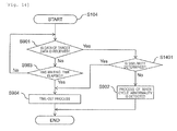
- FIG. 14 is a flow chart of a process occurring when a short cycle is detected, in the second example.
- FIG. 15 is an example of a filter table in the second example.
- FIG. 16 is an example of an abnormality-related information log.
- the details of the invention will be described, with an apparatus and a system in a network such as an in-vehicle network performing periodical data transmission and reception, as examples of the preferred embodiments (examples) of the invention.
- a network such as an in-vehicle network performing periodical data transmission and reception
- the invention is suitable for an in-vehicle network device and a data sending and receiving system in an in-vehicle network, the invention is also applicable to others besides the network device and the data sending and receiving system.
- FIG. 2 illustrates an outline of a control system provided with a network system having a network device employing the invention.
- a control system 1 provided inside the vehicle includes a network system 2 configured with an in-vehicle network (Controller Area Network (CAN), FlexRay (registered trademark), Ethernet (registered trademark), and the like), a wireless communication unit 3 that performs wireless communication with devices outside of the control system 1 (for example, communication using a mobile phone, and communication using the protocol such as wireless LAN and WAN), a network system 4 using a protocol different from or the same as that of the network system 2 , a wired communication unit 5 that includes a diagnostic terminal such as an on board diagnosis (OBD) terminal, and an external connection terminal such as an Ethernet terminal, an external recording medium (for example, a USB memory, an SD card, and the like), and performs an access to the network system 2 by wired connection through the external connection terminal, and an output device 6 which is connected to the network system 2 in a wired or wireless manner, receives data sent from the network system 2 , and displays or outputs information such as message information (for example, a video, or sound) based on the received
- the network system 2 is connected to devices such as the network system 4 , the wireless communication unit 3 , the wired communication unit 5 , and the output device 6 , and transmits and receives information between respective devices.
- FIG. 3 illustrates an internal configuration of the network system 2 .
- the network devices on the network system are connected to a network bus 301 , and the network bus 301 is, for example, a CAN bus, or the like.
- Electronic control unit (ECU) 302 that is connected to hardware, is not illustrated, and performs control of and data transmission and reception with the hardware on the network bus, and a gateway (hereinafter, GW) 303 that connects network buses and performs data transmission and reception between the respective network buses is connected to the network bus 301 .
- GW gateway
- the GW 303 may be an ECU having a GW function
- the ECU 302 may be a GW having a function of an ECU
- the GW 303 and the ECU 302 may each have both functions.
- each network device may control the hardware that is connected to the network device.
- an actuator not illustrated, is connected to the ECU 302 , and the ECU 302 controls a control target by manipulating the actuator.
- the output unit 6 is connected to the network bus, and the network device controls the output device 6 through the network bus as will be described below.
- the GW 303 is connected to a plurality of network buses, an ID is given to each network bus during an internal process of the GW 303 , and thus it is possible to identify which network bus for the process is used, from this ID.
- the ID for performing this identification is called a bus ID.
- the bus ID is also called a “Channel ID”.
- a bus-type connection used in the CAN is illustrated, as the topology of the network system 2 , but the invention is also similarly applicable to different topologies such as a star-type, a mesh-type, and a ring-type.
- FIG. 4 is a diagram illustrating an internal configuration of the GW 303 which is a network device according to the invention.
- the GW 303 includes a processor 401 such as a CPU that has a storage element such as a cache or a register and executes control, a communication I/F 402 transmitting and receiving data with a plurality of network buses 301 , a timer 403 that manages time and timing using a clock, that is not illustrated, a read only memory (ROM) 404 that stores programs and non-volatile data, a random access memory (RAM) 405 that stores non-volatile data, and an internal bus 406 used for communication in the inside of the network device.
- ROM read only memory
- RAM random access memory
- the internal configuration of the ECU 302 is also similar to the internal configuration of the GW 303 , but is different in that without a function of the GW, the ECU 302 does not perform a data transfer process between network buses.
- FIG. 5 illustrates a configuration of a software module running on the network device.
- a filter table 504 to be described later and a reception time table 505 to be described later are stored in the RAM 405 .
- the processor 401 executes respective modules such as a communication management unit 502 that manages the operation and status of the communication I/F 402 and issues an instruction to the communication I/F 402 through the internal bus 406 , a time management unit 503 that obtains information about time and performs control by managing the timer 403 , and a control unit 501 that analyzes data obtained from the communication I/F 402 , and performs overall control of the software modules.
- the network device also includes an abnormality-related information log 506 that records the abnormality-related information to be described later. The abnormality-related information log 506 is Recorded in the RAM 405 .
- FIG. 5 illustrates the operation concept of the processor 401 , and the processor 401 appropriately acquires information necessary for the operation from the ROM 404 and the RAM 405 , and performs the operation.
- FIG. 6 illustrates an example of a data structure according to a communication protocol used in the network bus 302 .
- FIG. 6 illustrates the data structure of a frame in the CAN communication protocol.
- the numerical values illustrated in FIG. 6 represent the number of bits in each field constituting the frame.
- the network device connected to the same bus in CAN performs communication by setting the bus signal to the dominant (0) during transmission, and detecting the dominant (0) or the recessive (1) of the bus signal during transmission or reception.
- Start of frame indicates the starting position of the frame, and is also used to synchronize the frame.
- An identifier indicates an ID of data transmitted in the frame (hereinafter, data ID), and the type of data that is transmitted in the frame can be identified by the data ID.
- a portion that is configured with the identifier (ID) and a remote transmission request (RTR) bit is referred to as an arbitration field, and the arbitration of a bus is performed by using the value in the arbitration field.
- RB 1 and RB 0 in the control field are reserved bits, and are set to dominant in the example of the format of FIG. 6( a ) .
- a data length code represents a data length (number of bytes) of the data field.
- the value of RB 0 is set to recessive, the value represents that the arbitration field has an extended format as illustrated in FIG. 6( b ) , and the identifier (ID) can be represented by 29 bits in this extended format.
- the structure of the data field and the subsequent fields following the control field in the extended format is the same as FIG. 6( a ) .
- the data field represents the contents of data to be transmitted, and data of N bytes is transmitted in a variable length.
- the CRC of the frame is input to the CRC field, and a CRC boundary is always set to recessive and transmitted for the acknowledgment boundary.
- a receiving node in this example, the ECU 302 or the GW 303 ) properly receives data, it returns a response for the transmitted data by setting the bit in the acknowledgment to dominant for the response.
- the end of frame indicates the end of the frame, and has 7 recessive bits.
- the network devices perform transmission and reception of data with each other in the format described above.
- a specific network device periodically transmits a value that the network device has observed (for example, the value of a sensor) to the network, and performs a process of notifying other network devices of the state (a value observed by the sensor).
- a network device with a low-priority stops the transmission.
- a data frame having a large ID in other words, a data frame in which less dominant bits have been transmitted during the arbitration cycle is defined to have a lower priority. Therefore, even if each network device intends to transmit data periodically, despite being capable of transmitting data at the transmission timing of data, when interruption occurs in the transmission process as the result of the arbitration in the arbitration field, or another network device has already transmitted data at the transmission start timing, it is not possible to transmit data and there is a possibility of deviation in the transmission cycle.
- the state in which the transmission timings of data overlap each other, or a bus is used when data is intended to be transmitted is called collision.
- the CAN has been described as an example, but data transmission and reception is periodically performed, for example, in a protocol such as Flexray (registered trademark). Moreover, in the example such as Ethernet, data transmission and reception are periodically performed in a different format, a process of periodically sending information is performed, and it can be similarly applicable to the invention.
- a protocol such as Flexray (registered trademark).
- Ethernet data transmission and reception are periodically performed in a different format, a process of periodically sending information is performed, and it can be similarly applicable to the invention.
- the processor 401 reads a data ID that needs to be received in the network device, which is set at a design time, from the filter table 504 , and specifies the data ID to the communication I/F 402 .
- the communication I/F 402 that has received the specified data ID that needs to be received monitors signals transmitted on the network bus 301 to which the network device is connected, and performs a data reception process of receiving the data frame having the data ID, and notifying the processor 401 of the reception of the data and the data of the data frame, when a data frame having a specified data ID is transmitted on the network bus 301 .
- the output device 6 is connected to the GW 303 and the ECU 302 , through a communication channel such as a dedicated line or a network bus 301 , receives for example, a data frame in which data of data ID 0x300 is defined as a warning screen display request and data of data ID 0x301 is defined as cycle abnormality log information, described later, displayed on the warning screen, as data of a data format defined by the network protocol described above, and which are transmitted from the GW 303 and the ECU 302 , from such a communication channel, creates image information such as diagrams and text information corresponding to the data, and displays the image information on a display included in the output device 6 .
- a communication channel such as a dedicated line or a network bus 301
- data of data ID 0x302 is a warning lamp lighting request and a value stored in the payload of the data specifies a lighting pattern of a warning lamp, and the warning lamp may be lighted when the data is received.
- data of data ID 0x303 is a warning sound output request and a value stored in the payload of the data specifies a pattern for warning sound, and when such data is received, the output device 6 may output the sound designated from among the sounds of sound patterns which are held therein, to the speaker.
- the output device 6 notifies the user of the status of the control system by outputting the message information about the state of the detected control system (in particular, abnormality occurrence).
- FIG. 7( a ) illustrates an example of a data transmission operation at a normal time, represents the transmission cycle of the data frame 701 with the elapse of time indicated on the horizontal axis, and represents the state in which the data frame 701 of the format illustrated in FIG. 6 is transmitted from a certain network device, for every predetermined cycle (T).
- T predetermined cycle
- a state is illustrated in which only the data frames with a certain data ID are transmitted.
- the delay occurs in the transmission time at time T 2 due to a collision with a data frame with another data ID which is not indicated in FIG. 7( a ) .
- FIG. 7( b ) illustrates a state of data transmission when a spoofing attack is taking place.
- the data frame 703 transmitted by the spoofing attack has the same data ID as that of a normal data frame 702
- the data frame 703 is transmitted at a timing different from the transmission timing of the original data frame 702 , in the same cycle as the data frame 702 . Therefore, the network device that receives data of this data ID cannot determine which of the data is correct, and there is a possibility of performing erroneous operations.
- the generation cycle on the network bus of the data frame with a specific data ID is shorter than the original transmission cycle T, and the network device on the receiving side receives data, for example, at each time X or at each time T-X in FIG. 7 ( b ) .
- the first embodiment of the invention will be illustrated later.
- an example is illustrated in which the invention is applied to the GW 303 in FIG. 3 .
- the data structure of the filter table 504 included in the GW 303 will be described with reference to FIG. 8 .
- the filter table 504 stores a data ID 802 of a received data frame, and a data transmission cycle 803 (hereinafter, a predetermined cycle) for each data ID.
- a data generation bus IDs 804 which are bus IDs of the network buses connected to the network devices transmitting data frames with respective data IDs.
- a determination as to the presence or absence of the spoofing attack is performed based on these types of information.
- These types of information registered in the filter table 504 are determined at the time of design of the entire system, and are registered before the start of the system.
- the communication management unit 502 detects the reception. Then, the communication management unit 502 obtains the reception time of the data from the time management unit 503 at the timing of detecting the reception of the data frame, and notifies the control unit 501 of the content of the received data and the reception time of the data.
- FIG. 1 illustrates a flow chart of a cycle determination process.
- the cycle determination process first, a determination as to whether the data ID of the received data exists in the filter table 504 (S 101 ) is performed. If the data ID of the received data does not exist in the filter table 504 (S 101 : No), since the data frame having the data ID which was not originally supposed to be transmitted is transmitted, a process occurring when ID abnormality is detected is performed (S 102 ).
- the filter table 504 In the determination as to whether or not the data ID of the received data is present in the filter table 504 at S 101 , if a data generation bus ID is present in the filter table 504 , it is also checked whether or not the ID of the network bus that has received the data and the data generation bus in the filter table 504 match each other. Since this enables not only matching of the data IDs but also checking of the matching of the data generation buses, it is possible to recognize the data transmission from buses other than the network bus from which data has originally been transmitted, and it becomes easier to detect cycle abnormality.
- step S 101 if the data ID of the received data is present in the filter table 504 (S 101 : Yes), the process of step S 103 will be performed next.
- the control unit 501 calculates the reception cycle of the data frame indicated by the data ID of the received data by comparing the reception time included in the notification from the communication management unit 502 with the previous reception time of the same data ID that the control unit 501 has previously stored in the reception time table 505 in a process at an end time which will be described later, and performs a cycle determination of comparing the reception cycle from the calculation result with the cycle in the filter table 504 . If it is determined to be abnormal, from the result of the cycle determination (S 103 : No), a process occurring when a short cycle is detected is performed (S 104 ). The process occurring when a short cycle is detected will be described later.
- the case where it is determined to be abnormal from the cycle determination refers to the case where the reception cycle which is calculated based on the previous reception time is less than the cycle of the corresponding data ID stored in the filter table 504 .
- the margin for error may be calculated and determination may be performed. Specifically, when the cycle stored in the filter table is 10 ms, a margin of 10% is obtained; and when the reception cycle is less than 9 ms, it is determined as a short cycle. Thus, even if the cycle is disturbed by collision or the like, it is less likely to be erroneously determined as a short cycle.
- the process at an end time (S 105 ) is performed.
- the reception time of receiving the data ID is stored in the reception time table 505 , as illustrated in FIG. 13 , and is used as the previous reception time of the data indicated by the data ID.
- the reception time table 505 is configured to record the reception time of the data frame for each data ID ( 1301 ), and in the process at an end time, the reception time is recorded in the column of the previous reception time ( 1302 ) corresponding to the data ID.
- control unit 501 performs detection of a state in which the data frame is transmitted at a cycle shorter than the cycle which has been determined in advance.
- the process occurring when a short cycle is detected is a process occurring when it is determined that the data frame having the same data ID has been received at a cycle shorter than the cycle which has been determined in advance, and determines whether or not the subsequent data frame having the same data ID is received within a certain period of time.
- the control unit 501 waits for data reception of the data frame having the data ID for which a short cycle has been detected. Therefore, the control unit 501 monitors the data ID of the data frame of which notification is sent from the communication management unit 502 , and performs a process occurring when cycle abnormality is detected which will be described later (S 902 ), if notification of the reception of the data frame of the data ID for which a short cycle has been detected is sent (S 901 : Yes). If the data of the data ID for which a short cycle has been detected is not received (S 901 : No), the control unit 501 performs the process of FIG. 1 on the data frame of which notification of the reception is sent, and checks whether or not the waiting time has elapsed in the process of step S 903 .
- the waiting time represents a time up to the data reception time at a normal cycle that is assumed for the previous reception time which is a reference, and corresponds to a time of (cycle T ⁇ time X) in FIG. 7( b ) .
- the calculation including a margin may be performed for the waiting time.
- the waiting time resulted from the calculation is 2 ms (for example, in the case of assuming reception at intervals of 10 ms, reception of data of the same data ID after 8 ms from the previous reception)
- 20% of the time of the cycle which is registered in the filter table is defined as the margin of the waiting time, rather than 2 ms obtained from the calculation, in consideration of the disturbance of the transmission cycle due to the occurrence of collision, and the waiting time may be 4 ms obtained by adding 2 ms corresponding to this margin.
- the control unit 501 waits for a predetermined time process and performs step S 901 again.
- the waiting time has elapsed (S 903 : Yes)
- it performs a time-out process (S 904 ).
- time-out process S 904 when the time-out occurs (when the waiting time has elapsed), there is a high possibility that the data that has been detected as having a short cycle is actually normal data for which only a cycle has been shortened due to disturbance on the transmission cycle on the network bus, and spoofing data has not been received, such that a process occurring when data is determined to be received normally (for example, data transfer process) is first performed on the data determined as having a short cycle.
- the periodicity for a data frame with the data ID of the data that is detected to be a short cycle is checked, and it is checked whether there is no unauthorized data transmission.
- the calculation in this manner enables avoiding erroneous determination as a short cycle due to periodic disturbances caused by temporary collision.
- the processor 401 monitors the reception cycle of a data frame through the communication I/F 402 for a certain cycle of time since the recovery from the start-up or standby state, and registers the reception cycle in the filter table 504 . By doing so, it becomes unnecessary to register in advance a design cycle in the filter table 504 .
- the following processes are performed: (1) discarding of the received data without processing it, (2) recording of abnormality type (ID abnormality and cycle abnormality) and the number of abnormality occurrences (a cumulative value) as abnormality log information, when the abnormality occurrence is detected, (3) implementation of an abnormality notification process for notifying of the abnormality, and the like.
- the network device that has detected abnormality notifies the output device 6 of abnormality-related information described later through the communication channel, and the output device 6 displays the abnormality-related information as message information indicating that the abnormality is detected.
- the output process of the message information is as described above.
- FIG. 10 illustrates an example of message information display.
- FIG. 10 illustrates an example in which message information 1001 is displayed on the display 1000 provided in the output device 6 .
- the displayed example represents information such as “data ID” ( 1002 ) that is a data ID of a data frame in which an abnormality is detected, “data type” ( 1003 ) representing a specific data type such as “vehicle speed” associated with the data ID, “number of occurrences” ( 1004 ) representing the number of abnormality occurrences as a cumulative value, “latest occurrence time” ( 1005 ) that is the most recent time that abnormality is detected, and “generation bus ID” ( 1006 ) that is a bus ID of a network bus in which abnormality is detected.
- the information indicated by the message information is referred to as abnormality-related information. It is possible to notify the user of the abnormality occurrence in a network and the details as a warning, by presenting the information.
- the control unit 501 performs an abnormality notification process of transmitting a predetermined specific signal (warning signal) to the network bus 301 .
- a predetermined specific signal warning signal
- the network device such as the ECU 302 or the GW 303 that has received the specific signal detects the occurrence of the cycle abnormality in the network
- the network device performs, for example, a process of stopping the system after controlling the hardware under the control of the network device so as to be in a predetermined safe state, and notifying the other communication devices of the implementation of the fail-safe control, or the like. By doing so, it becomes possible to stop the system in a safe state when the cycle abnormality is detected.
- targets to which the network device having detected the cycle abnormality transmits a warning signal are network devices that are connected to the wireless communication unit 3 , the wired communication unit 5 , or a plurality of network buses, it is possible to make the entire system be in a fail-safe state by sending the notification to network buses other than the network bus that has detected the cycle abnormality, or other network systems.
- a network device that has detected abnormality, or a network device that has received the cycle abnormality notification process stores the abnormality-related information as abnormality-related information log 506 inside the network device.
- FIG. 16 illustrates the data structure of the abnormality-related information log 506 .
- the data ID of a data frame in which abnormality is detected is recorded in a data ID 1601
- the accumulated number of times when abnormality occurs is recorded in the number of occurrences 1602
- a time that has been determined to be abnormal is recorded in a last occurrence time 1603
- a bus ID of a network bus in which abnormality occurs is recorded in a occurred bus ID 1604 , respectively, thereby the abnormality-related information log is configured.
- the received data is discarded without being processed as an example of the process occurring when abnormality is detected, when cycle abnormality occurs, for example, even when a large amount of data with normal identifier is transmitted by communication channel saturation attack such as denial of service (DoS), and the like, data transmitted at an interval of a predetermined cycle or less is discarded, and thus it becomes possible to prevent attacks.
- DoS denial of service
- Example 2 an example will be described in which the presence or absence of cycle abnormality is performed on consideration of a similarity determination process of comparing the content of received data in a process occurring when a short cycle is detected.
- Example 2 The configuration of a network device in Example 2 is the same as in the case of Example 1, and the process occurring when a short cycle is detected in the control unit 501 is a process of a flow chart illustrated in FIG. 14 instead of the process of FIG. 9 .
- Example 2 in the process occurring when a short cycle is detected S 104 , when the notification of the reception of the data frame having the data ID of a determination target is sent (S 901 : Yes), a similarity determination process of comparing the content of the data of a data frame at a time of cycle abnormality detection with that of a data frame that has been received until the waiting time has elapsed since then is performed (S 1401 ).
- S 1401 determines the determination result is normal
- the process occurring when cycle abnormality is detected S 902 is not performed, and the time-out process S 904 is performed regarding that normal data frame is received.
- the meaning that the determination result from the similarity determination process is normal is that, for example, the difference value between the data fields in two data frames is equal to or less a predetermined certain amount (difference upper limit) or a constant ratio, the indicated states are the same (the statuses representing ON/OFF are both ON, or the like), and the difference value is within the range of the value determined based on the data type that the data field means such as a design reference value (a normal range).
- a design reference value a normal range
- the determination result from the similarity determination process is abnormal in the case where the difference value is greater than the difference upper limit, the states (values) are not equal, any value is outside the normal range, and the like.
- S 1401 No
- FIG. 15 illustrates the data structure of the filter table 504 in Example 2.
- the filter table 504 stores values to be compared with the difference value of data field used in the similarity determination process.
- a design reference value (normal range) 1501 As the value to be compared with the difference value of data field, there is a design reference value (normal range) 1501 , and a difference upper limit 1502 . These values are determined in advance for each data ID at the time of system design, for example, in the case of data of the data type “vehicle speed”, a normal range: 0 to 300 and a difference upper limit: 5 are determined in advance for the data ID: 0x001 corresponding thereto, and registered in the filter table 504 .
- cycle abnormality is detected in this way, the content of data of the data frame with the corresponding data ID is checked, and the occurrence of cycle abnormality is determined, such that it is possible to detect the cycle abnormality while preventing erroneous detection due to the collision occurred at the normal time.
- Example 3 is different from Example 1 in that the control unit 501 performs a transfer process S 1102 after performing the process occurring when cycle abnormality is detected as illustrated in FIG. 11 and the filter table 504 contains the information about the data transfer destination bus ID as illustrated in FIG. 12 .
- the following description will be given regarding the process in the control unit 501 with reference to the flowchart in FIG. 11 .
- the processes of S 101 to S 104 when the control unit 501 receives the notification of the data reception are the same as those of Example 1.
- the process of the cycle determination (S 103 ) is performed in the same manner as Example 1, and if the cycle resulted from the calculation is determined not to be abnormal by comparing the cycle with that in the filter table 504 (S 103 : Yes), a determination as to whether or not the relevant data ID is data to be transferred (S 1101 ).
- the determination as to whether or not the data ID is data to be transferred checks the value of the data transfer destination bus ID ( 1201 ) corresponding to the data ID of the received data, based on the filter table 504 illustrated in FIG.
- the data transfer destination bus ID is set to ‘B’, such that it is considered that it is necessary to perform a transfer process of data frame on the network bus having the bus ID ‘B’, and the data is determined to be the transfer target data.
- the data transfer destination bus ID there is no value in the data transfer destination bus ID, such that the data frame is determined not to be transfer target data and there is no need to perform a transfer process.
- the process proceeds to the process at an end time S 105 without performing the transfer process of the data frame. Further, if the received data is determined to be the transfer target data (S 1101 : Yes), the process performs the transfer process S 1102 and proceeds to the process at an end time.
- the reception cycle is determined to be normal in step S 103 , the process is performed as described above.
- the process occurring when a short cycle is detected is performed (S 104 ).
- the process of the control unit 501 in this case is the same as the case in Example 1, but the processes in the time-out process S 904 are different.
- a process occurring when the data is determined to be received normally for example, data transfer process
- Example 3 with respect to reception data that is first determined as having a short cycle, a determination as to whether or not the reception data is transfer target data by the same determination process as in S 1101 is performed, and when the reception data is determined to be the transfer target data, the data is transferred.
- data frame is not immediately transferred to another network bus, but is temporarily held in the GW 303 , and thereafter, when cycle abnormality is detected, it is possible to prevent unauthorized data transfer by discarding the data.
- Example 4 examples have been described in which any of the ECU or the GW performs the cycle determination, however, in Example 4, an example will be described in which the ECU 302 that actually receives data performs a cycle determination and prevents unauthorized data processing.
- the configuration example of the ECU 302 in Example 3 is similar to the configuration described in Example 1, with respect to the process of the control unit 501 , in the process at a time of short cycle detection S 104 , the content of the process occurring when cycle abnormality is detected S 902 and a time-out process S 904 are different from Example 1.
- the subsequent unauthorized data is not received until the waiting time has elapsed, such that it is determined to be a disturbance in a cycle rather than spoofing attack, a process occurring when data is received at a normal time is performed on the data received by the ECU.
- Example 5 the abnormality-related information has been recorded as the abnormality-related information log 506 at the time of abnormality occurrence detection, after the abnormality occurs, the user is notified of the abnormality by using the abnormality-related information that has been recorded, or different processes are performed depending on the number of abnormality occurrences.
- Example 5 abnormality-related information recorded in the cycle abnormality log information 506 is read at a certain timing when the control unit 501 is started, ended, or diagnosed, and similarly to message information output by the abnormality notification process described above, the abnormality-related information is output to the output device 6 through the communication channel, such that it is possible to check the abnormality-related information after cycle abnormality occurs.
- Example 1 to Example 5 described above with respect to the identifiers (ID) which are targets of fraud detection, not only the identifiers of all pieces of data on the network may be targets, but also data of a specific identifier may be focused and targets of fraud detection. Specifically, a process of limiting a reception target only to specific data IDs is performed in the data reception process by the communication I/F 402 described above. By limiting the targets of fraud detection, it becomes possible to reduce the processing load in the processor 401 , and also to save a data receiving area of the communication I/F 402 : resources be used for fraud detection such as a mailbox.
- automotive safety integrity level (ASIL) of the function associated with data as the importance degree of data is registered in advance in the filter table 504 , and only data having a high importance degree of ASIL A or more may be the targets of fraud detection.
- ASIL automotive safety integrity level
- the targets of fraud detection may be changed periodically. Specifically, a process of sequentially switching specific data IDs which are reception targets is performed in the data reception process by the communication I/F 402 described above.
- the number of identifiers of the targets of fraud detection is constrained to ten types by resource constraints, and the number of types of the identifier on the network is 30, it is possible to detect fraud while saving resources, by changing the identifiers to be processed in three patterns by ten types by switching the table in which the identifiers of the targets of fraud detection are registered at a certain timing. Further, it is possible to easily perform the fraud detection for the data having a high importance degree while saving resources, by scheduling the switching of patterns such that fraud is detected for the data having a high importance degree for a long time, depending on the importance degree of the data.
- cycle abnormality when cycle abnormality occurs, it becomes possible to prevent erroneous detection due to cycle abnormality, by determining whether or not there is an unauthorized attack by comparing the contents of respective pieces of data, and it is possible to reduce the processing load of the data comparison by comparing the contents of data only when the cycle abnormality occurs.
- the cycle abnormality detected it is possible to notify the user or the like of the fraud occurrence and the detailed information, by notifying an output device or an external system or the like of the abnormality occurrence and message information including various types of abnormality-related information. Further, information is saved, and thus it becomes possible to check the information of when the fraud has occurred in the past.
Landscapes
- Engineering & Computer Science (AREA)
- Computer Networks & Wireless Communication (AREA)
- Signal Processing (AREA)
- Computer Security & Cryptography (AREA)
- Computer Hardware Design (AREA)
- Computing Systems (AREA)
- General Engineering & Computer Science (AREA)
- Small-Scale Networks (AREA)
Abstract
Description
- PTL 1: JP-A-2008-236408
- PTL 2: JP-A-2004-193903
Waiting time=cycle in filter table−(data reception time−previous reception time) (Equation 1)
Waiting time=cycle in filter table−(data reception timing−previous reception timing)−previous reception error (Equation 2)
-
- 1 CONTROL SYSTEM
- 2 NETWORK SYSTEM
- 3 WIRELESS COMMUNICATION UNIT
- 4 NETWORK SYSTEM
- 5 WIRED COMMUNICATION UNIT
- 6 OUTPUT DEVICE
- 301 NETWORK BUS
- 302 ECU
- 303 GATEWAY (GW)
- 401 PROCESSOR
- 402 COMMUNICATION I/F
- 403 TIMER
- 404 ROM
- 405 RAM
- 406 INTERNAL BUS
- 501 CONTROL UNIT
- 502 COMMUNICATION MANAGEMENT UNIT
- 503 TIME MANAGEMENT UNIT
- 504 FILTER TABLE
- 505 RECEPTION TIME TABLE
- 506 ABNORMALITY-RELATED INFORMATION LOG
- 1000 DISPLAY
- 1001 MESSAGE INFORMATION
Claims (7)
Applications Claiming Priority (3)
| Application Number | Priority Date | Filing Date | Title |
|---|---|---|---|
| JP2013012772A JP5919205B2 (en) | 2013-01-28 | 2013-01-28 | Network device and data transmission / reception system |
| JP2013-012772 | 2013-01-28 | ||
| PCT/JP2013/084209 WO2014115455A1 (en) | 2013-01-28 | 2013-12-20 | Network device and data sending and receiving system |
Publications (2)
| Publication Number | Publication Date |
|---|---|
| US20150358351A1 US20150358351A1 (en) | 2015-12-10 |
| US9794286B2 true US9794286B2 (en) | 2017-10-17 |
Family
ID=51227255
Family Applications (1)
| Application Number | Title | Priority Date | Filing Date |
|---|---|---|---|
| US14/763,597 Expired - Fee Related US9794286B2 (en) | 2013-01-28 | 2013-12-20 | Network device, and data sending and receiving system |
Country Status (5)
| Country | Link |
|---|---|
| US (1) | US9794286B2 (en) |
| EP (1) | EP2950482B1 (en) |
| JP (1) | JP5919205B2 (en) |
| CN (1) | CN104956626B (en) |
| WO (1) | WO2014115455A1 (en) |
Cited By (12)
| Publication number | Priority date | Publication date | Assignee | Title |
|---|---|---|---|---|
| US20160344601A1 (en) * | 2015-05-18 | 2016-11-24 | Denso Corporation | Relay apparatus |
| US20180144119A1 (en) * | 2015-08-31 | 2018-05-24 | Panasonic Intellectual Property Corporation Of America | Misuse detection method, misuse detection electronic control unit, and misuse detection system |
| US20210126917A1 (en) * | 2019-04-23 | 2021-04-29 | Huawei Technologies Co., Ltd. | In-Vehicle Gateway Communication Method, In-Vehicle Gateway, and Intelligent Vehicle |
| US20210203525A1 (en) * | 2015-08-31 | 2021-07-01 | Panasonic Intellectual Property Corporation Of America | Gateway device determining whether or not received frame is appropriate |
| US20210281595A1 (en) * | 2019-07-04 | 2021-09-09 | Panasonic Intellectual Property Corporation Of America | Anomaly detection device and anomaly detection method |
| US11190546B2 (en) | 2019-05-31 | 2021-11-30 | QDroid Inc. | Secure failsafe apparatus |
| US11190533B2 (en) * | 2016-07-05 | 2021-11-30 | Panasonic Intellectual Property Corporation Of America | Anomaly detection electronic control unit, onboard network system, and anomaly detection method |
| US11252057B2 (en) | 2019-03-14 | 2022-02-15 | Panasonic Intellectual Property Management Co., Ltd. | Information processing apparatus, information processing system, information processing method, and computer program |
| US11296970B2 (en) | 2017-06-23 | 2022-04-05 | Robert Bosch Gmbh | Method for detecting a disruption in a vehicle's communication system by checking for abnormalities in communication |
| US11362857B2 (en) * | 2018-08-30 | 2022-06-14 | Apollo Intelligent Driving Technology (Beijing) Co., Ltd. | Message processing method, apparatus, electronic control unit and readable storage medium |
| US11388566B2 (en) * | 2019-10-31 | 2022-07-12 | Toyota Jidosha Kabushiki Kaisha | Communication device, abnormality determination device, method, and storage medium |
| US20220340093A1 (en) * | 2018-12-11 | 2022-10-27 | Autonetworks Technologies, Ltd. | Joint connector |
Families Citing this family (154)
| Publication number | Priority date | Publication date | Assignee | Title |
|---|---|---|---|---|
| KR101519777B1 (en) * | 2014-01-29 | 2015-05-12 | 현대자동차주식회사 | Data trasmission method between controllers in a vehicle Network and data reception method between Controllers in the vehicle network |
| JP6651662B2 (en) * | 2014-04-17 | 2020-02-19 | パナソニック インテレクチュアル プロパティ コーポレーション オブ アメリカPanasonic Intellectual Property Corporation of America | Fraud detection electronic control unit and fraud detection method |
| EP3142289B1 (en) | 2014-05-08 | 2020-10-07 | Panasonic Intellectual Property Corporation of America | In-vehicle network system, electronic control unit, and irregularity detection method |
| EP3480064B1 (en) | 2014-09-12 | 2020-08-19 | Panasonic Intellectual Property Corporation of America | Vehicle communication device, in-vehicle network system, and vehicle communication method |
| JP6849782B2 (en) * | 2014-09-12 | 2021-03-31 | パナソニック インテレクチュアル プロパティ コーポレーション オブ アメリカPanasonic Intellectual Property Corporation of America | Electronic control unit, in-vehicle network system and vehicle communication method |
| US10432421B2 (en) | 2014-11-20 | 2019-10-01 | National University Corporation Nagoya University | Communication control device and communication system |
| CN105981336B (en) * | 2014-12-01 | 2020-09-01 | 松下电器(美国)知识产权公司 | Abnormality detection electronic control unit, vehicle-mounted network system, and abnormality detection method |
| JP6369334B2 (en) * | 2015-01-09 | 2018-08-08 | トヨタ自動車株式会社 | In-vehicle network |
| US9661006B2 (en) * | 2015-03-31 | 2017-05-23 | Check Point Software Technologies Ltd. | Method for protection of automotive components in intravehicle communication system |
| US9571513B2 (en) * | 2015-04-23 | 2017-02-14 | International Business Machines Corporation | Monitoring device monitoring network |
| US10095634B2 (en) * | 2015-05-22 | 2018-10-09 | Nxp B.V. | In-vehicle network (IVN) device and method for operating an IVN device |
| US9825918B2 (en) | 2015-05-22 | 2017-11-21 | Nxp B.V. | Controller area network (CAN) device and method for operating a CAN device |
| US9935774B2 (en) | 2015-05-22 | 2018-04-03 | Nxp B.V. | Configurable cryptographic controller area network (CAN) device |
| WO2016194123A1 (en) * | 2015-06-02 | 2016-12-08 | 三菱電機ビルテクノサービス株式会社 | Relay device, network monitoring system, and program |
| US9686294B2 (en) | 2015-06-15 | 2017-06-20 | Check Point Software Technologies Ltd. | Protection of communication on a vehicular network via a remote security service |
| JP6497656B2 (en) | 2015-07-03 | 2019-04-10 | パナソニックIpマネジメント株式会社 | COMMUNICATION METHOD AND COMMUNICATION DEVICE USING THE SAME |
| JP6528239B2 (en) * | 2015-07-10 | 2019-06-12 | パナソニックIpマネジメント株式会社 | Communication device and program |
| JP6532162B2 (en) * | 2015-08-12 | 2019-06-19 | 本田技研工業株式会社 | Communication device and communication system |
| JP6480291B2 (en) * | 2015-08-28 | 2019-03-06 | 株式会社日立製作所 | Communication device, transmission device, and reception device |
| WO2017037977A1 (en) | 2015-08-31 | 2017-03-09 | パナソニック インテレクチュアル プロパティ コーポレーション オブ アメリカ | Gateway apparatus, in-vehicle network system, and communication method |
| CN112261026B (en) * | 2015-08-31 | 2023-02-28 | 松下电器(美国)知识产权公司 | Abnormality detection method, abnormality detection electronic control unit, and abnormality detection system |
| JP6525824B2 (en) * | 2015-08-31 | 2019-06-05 | 国立大学法人名古屋大学 | Relay device |
| JP6276738B2 (en) * | 2015-09-02 | 2018-02-07 | Fdk株式会社 | CAN communication unit and CAN communication program |
| US9954892B2 (en) | 2015-09-28 | 2018-04-24 | Nxp B.V. | Controller area network (CAN) device and method for controlling CAN traffic |
| US10361934B2 (en) * | 2015-09-28 | 2019-07-23 | Nxp B.V. | Controller area network (CAN) device and method for controlling CAN traffic |
| WO2017061079A1 (en) | 2015-10-09 | 2017-04-13 | パナソニック インテレクチュアル プロパティ コーポレーション オブ アメリカ | Security device, attack detection method, and program |
| JP6173541B2 (en) | 2015-10-09 | 2017-08-02 | パナソニック インテレクチュアル プロパティ コーポレーション オブ アメリカPanasonic Intellectual Property Corporation of America | Security device, attack detection method and program |
| JP6286749B2 (en) * | 2015-10-21 | 2018-03-07 | 本田技研工業株式会社 | COMMUNICATION SYSTEM, CONTROL DEVICE, AND CONTROL METHOD |
| CA3004893A1 (en) * | 2015-11-12 | 2017-05-18 | Mercury Systems, Inc. | Broadcast bus frame filter |
| JP6566400B2 (en) * | 2015-12-14 | 2019-08-28 | パナソニックIpマネジメント株式会社 | Electronic control device, gateway device, and detection program |
| JP6649215B2 (en) * | 2015-12-14 | 2020-02-19 | パナソニック インテレクチュアル プロパティ コーポレーション オブ アメリカPanasonic Intellectual Property Corporation of America | Security device, network system, and attack detection method |
| CN112286764B (en) * | 2015-12-14 | 2024-11-26 | 松下电器(美国)知识产权公司 | Security device, network system and attack detection method |
| JP6423402B2 (en) | 2015-12-16 | 2018-11-14 | パナソニック インテレクチュアル プロパティ コーポレーション オブ アメリカPanasonic Intellectual Property Corporation of America | Security processing method and server |
| CN112367318B (en) | 2015-12-16 | 2023-04-07 | 松下电器(美国)知识产权公司 | Security processing method and computer |
| EP3396900B1 (en) | 2015-12-25 | 2019-10-30 | Panasonic Intellectual Property Management Co., Ltd. | Fraudulent message detection |
| KR101721035B1 (en) * | 2016-01-07 | 2017-03-30 | 고려대학교 산학협력단 | Appratus and method for detecting vehicle intrusion |
| WO2017119027A1 (en) * | 2016-01-08 | 2017-07-13 | パナソニック インテレクチュアル プロパティ コーポレーション オブ アメリカ | Impropriety detection method, monitoring electronic control unit, and on-board network system |
| CN113014464B (en) * | 2016-01-08 | 2022-07-26 | 松下电器(美国)知识产权公司 | Abnormality detection method, abnormality detection device, and abnormality detection system |
| JP6684690B2 (en) * | 2016-01-08 | 2020-04-22 | パナソニック インテレクチュアル プロパティ コーポレーション オブ アメリカPanasonic Intellectual Property Corporation of America | Fraud detection method, monitoring electronic control unit and in-vehicle network system |
| JP6658045B2 (en) * | 2016-02-11 | 2020-03-04 | 株式会社デンソー | Communication device |
| US20170235698A1 (en) * | 2016-02-12 | 2017-08-17 | Nxp B.V. | Controller area network (can) message filtering |
| JP2019083355A (en) * | 2016-02-22 | 2019-05-30 | 株式会社日立製作所 | Communication control device and communication control method |
| CN108605004B (en) * | 2016-03-10 | 2020-12-25 | 本田技研工业株式会社 | Communication system |
| CN109644153B (en) * | 2016-04-12 | 2020-10-13 | 伽德诺克斯信息技术有限公司 | Specially programmed computing system with associated device configured to implement secure lockout and method of use thereof |
| US10785259B2 (en) * | 2016-04-19 | 2020-09-22 | Mitsubishi Electric Corporation | Relay device |
| EP3745657B1 (en) * | 2016-05-27 | 2022-03-09 | Panasonic Intellectual Property Corporation of America | Gateway device, vehicle network system, transfer method, and program |
| JP6561917B2 (en) * | 2016-06-03 | 2019-08-21 | 株式会社デンソー | Control device |
| JP6280662B2 (en) | 2016-07-05 | 2018-02-14 | パナソニック インテレクチュアル プロパティ コーポレーション オブ アメリカPanasonic Intellectual Property Corporation of America | Unauthorized control inhibition method, unauthorized control inhibition device and in-vehicle network system |
| WO2018008453A1 (en) | 2016-07-05 | 2018-01-11 | パナソニック インテレクチュアル プロパティ コーポレーション オブ アメリカ | Abnormality detecting electronic control unit, vehicle-mounted network system and abnormality detecting method |
| JP6849528B2 (en) | 2016-07-28 | 2021-03-24 | パナソニック インテレクチュアル プロパティ コーポレーション オブ アメリカPanasonic Intellectual Property Corporation of America | Frame transmission blocking device, frame transmission blocking method and in-vehicle network system |
| CN113783958A (en) | 2016-07-28 | 2021-12-10 | 松下电器(美国)知识产权公司 | Gateway device, method and in-vehicle network system |
| JP6433951B2 (en) * | 2016-08-09 | 2018-12-05 | 東芝デジタルソリューションズ株式会社 | Network monitoring device and program |
| JP6805667B2 (en) * | 2016-09-15 | 2020-12-23 | 住友電気工業株式会社 | Detection device, gateway device, detection method and detection program |
| US10567400B2 (en) | 2016-09-27 | 2020-02-18 | Fujitsu Limited | Attack detection device, attack detection method, and non-transitory computer-readable recording medium |
| CN113542304B (en) * | 2016-12-06 | 2024-08-23 | 松下电器(美国)知识产权公司 | Information processing apparatus and information processing method |
| JP6492234B2 (en) | 2016-12-06 | 2019-03-27 | パナソニック インテレクチュアル プロパティ コーポレーション オブ アメリカPanasonic Intellectual Property Corporation of America | Information processing apparatus and information processing method |
| JP6490879B2 (en) | 2016-12-06 | 2019-03-27 | パナソニック インテレクチュアル プロパティ コーポレーション オブ アメリカPanasonic Intellectual Property Corporation of America | Information processing apparatus and information processing method |
| JP6558703B2 (en) | 2016-12-14 | 2019-08-14 | パナソニックIpマネジメント株式会社 | Control device, control system, and program |
| CN108337228B (en) * | 2017-01-13 | 2020-11-10 | 株式会社自动网络技术研究所 | In-vehicle devices, relay devices, and media |
| JP6717214B2 (en) | 2017-01-18 | 2020-07-01 | 株式会社オートネットワーク技術研究所 | Communication device, communication system, and computer program |
| WO2018135098A1 (en) | 2017-01-18 | 2018-07-26 | パナソニックIpマネジメント株式会社 | Monitoring device, monitoring method, and computer program |
| JP6798349B2 (en) * | 2017-02-23 | 2020-12-09 | 株式会社デンソー | Communication system and relay device |
| JP6460137B2 (en) * | 2017-03-06 | 2019-01-30 | オムロン株式会社 | Control device, control method, and program |
| JP6515404B2 (en) * | 2017-03-13 | 2019-05-22 | 本田技研工業株式会社 | Communication device, communication method, and program |
| JP6956624B2 (en) | 2017-03-13 | 2021-11-02 | パナソニック インテレクチュアル プロパティ コーポレーション オブ アメリカPanasonic Intellectual Property Corporation of America | Information processing methods, information processing systems, and programs |
| JP2018157463A (en) * | 2017-03-21 | 2018-10-04 | オムロンオートモーティブエレクトロニクス株式会社 | On-vehicle communication system, communication management device, and vehicle controller |
| JP2018160851A (en) * | 2017-03-23 | 2018-10-11 | 株式会社オートネットワーク技術研究所 | On-vehicle communication device, computer program, and message determination method |
| JP6760185B2 (en) * | 2017-03-31 | 2020-09-23 | 住友電気工業株式会社 | Relay device, detection method and detection program |
| WO2018186053A1 (en) * | 2017-04-07 | 2018-10-11 | パナソニック インテレクチュアル プロパティ コーポレーション オブ アメリカ | Method for detecting unauthorized communication, system for detecting unauthorized communication, and program |
| JP6494821B2 (en) | 2017-04-07 | 2019-04-03 | パナソニック インテレクチュアル プロパティ コーポレーション オブ アメリカPanasonic Intellectual Property Corporation of America | Unauthorized communication detection standard determination method, unauthorized communication detection standard determination system and program |
| CN109076016B9 (en) * | 2017-04-07 | 2022-02-15 | 松下电器(美国)知识产权公司 | Illegal communication detection standard determination method, determination system, and recording medium |
| JP6539363B2 (en) | 2017-04-07 | 2019-07-03 | パナソニック インテレクチュアル プロパティ コーポレーション オブ アメリカPanasonic Intellectual Property Corporation of America | Illegal communication detection method, illegal communication detection system and program |
| JP6723955B2 (en) * | 2017-05-12 | 2020-07-15 | 日立オートモティブシステムズ株式会社 | Information processing apparatus and abnormality coping method |
| DE112018002549T5 (en) * | 2017-05-18 | 2020-04-09 | Bosch Corporation | Electronic control unit |
| KR101966345B1 (en) * | 2017-06-30 | 2019-04-08 | 주식회사 페스카로 | Method and System for detecting bypass hacking attacks based on the CAN protocol |
| WO2018230988A1 (en) | 2017-06-16 | 2018-12-20 | 주식회사 페스카로 | Can communication based hacking attack detection method and system |
| KR101972457B1 (en) * | 2017-06-16 | 2019-04-25 | 주식회사 페스카로 | Method and System for detecting hacking attack based on the CAN protocol |
| JP6891671B2 (en) | 2017-06-29 | 2021-06-18 | 富士通株式会社 | Attack detection device and attack detection method |
| JP7094670B2 (en) * | 2017-07-03 | 2022-07-04 | 矢崎総業株式会社 | Setting device and computer |
| JP6743778B2 (en) * | 2017-07-19 | 2020-08-19 | 株式会社オートネットワーク技術研究所 | Receiver, monitor and computer program |
| JP7033499B2 (en) * | 2017-07-26 | 2022-03-10 | パナソニック インテレクチュアル プロパティ コーポレーション オブ アメリカ | Anomaly detection device and anomaly detection method |
| JP7003544B2 (en) * | 2017-09-29 | 2022-01-20 | 株式会社デンソー | Anomaly detection device, anomaly detection method, program and communication system |
| DE102017218134B3 (en) | 2017-10-11 | 2019-02-14 | Volkswagen Aktiengesellschaft | A method and apparatus for transmitting a message sequence over a data bus and method and apparatus for detecting an attack on a message sequence thus transmitted |
| JP6556207B2 (en) * | 2017-10-19 | 2019-08-07 | 三菱電機株式会社 | Vehicle security device and security method |
| JP6911936B2 (en) * | 2017-10-30 | 2021-07-28 | 日本電信電話株式会社 | Attack communication detection device, attack communication detection method, program |
| DE102017128970A1 (en) * | 2017-12-06 | 2019-06-06 | Göpel electronic GmbH | Device and method for checking the specification-compliant behavior of control devices |
| CN111279657B (en) * | 2017-12-15 | 2023-05-23 | 松下电器(美国)知识产权公司 | Illegal detection device, in-vehicle network system, and illegal detection method |
| JP7071998B2 (en) | 2017-12-15 | 2022-05-19 | パナソニック インテレクチュアル プロパティ コーポレーション オブ アメリカ | In-vehicle network abnormality detection system and in-vehicle network abnormality detection method |
| JP7172043B2 (en) | 2018-01-19 | 2022-11-16 | 富士通株式会社 | Attack detection device and attack detection method |
| WO2019142476A1 (en) | 2018-01-22 | 2019-07-25 | パナソニック インテレクチュアル プロパティ コーポレーション オブ アメリカ | Data analysis device and program |
| JP7045286B2 (en) | 2018-01-22 | 2022-03-31 | パナソニック インテレクチュアル プロパティ コーポレーション オブ アメリカ | Data analysis device, data analysis method and program |
| JP7045288B2 (en) | 2018-01-22 | 2022-03-31 | パナソニック インテレクチュアル プロパティ コーポレーション オブ アメリカ | Data analysis device, data analysis method and program |
| CN110325410B (en) | 2018-01-22 | 2022-04-26 | 松下电器(美国)知识产权公司 | Data analysis device and storage medium |
| JP7247089B2 (en) | 2018-01-22 | 2023-03-28 | パナソニック インテレクチュアル プロパティ コーポレーション オブ アメリカ | Vehicle anomaly detection server, vehicle anomaly detection system, and vehicle anomaly detection method |
| JP6937887B2 (en) * | 2018-02-21 | 2021-09-22 | 三菱電機株式会社 | In-vehicle function access control system, in-vehicle device and in-vehicle function access control method |
| JP6881371B2 (en) | 2018-03-27 | 2021-06-02 | 株式会社オートネットワーク技術研究所 | Communication system, receiver, transmission interval change method and computer program |
| EP4250648A3 (en) | 2018-03-29 | 2023-12-06 | Panasonic Intellectual Property Corporation of America | Illicit act detection method, illicit act detection device, and program |
| EP3771981A4 (en) * | 2018-04-06 | 2021-04-14 | Panasonic Intellectual Property Corporation of America | NEWSPAPER PRODUCTION PROCESS, NEWSPAPER PRODUCTION DEVICE AND PROGRAM |
| JP6552674B1 (en) * | 2018-04-27 | 2019-07-31 | 三菱電機株式会社 | Inspection system |
| JP7035791B2 (en) | 2018-05-17 | 2022-03-15 | オムロン株式会社 | Anomaly detection device and anomaly detection method to detect cyber attacks |
| JP7178408B2 (en) * | 2018-05-23 | 2022-11-25 | パナソニック インテレクチュアル プロパティ コーポレーション オブ アメリカ | Abnormality detection device, abnormality detection system and control method |
| JP6555559B1 (en) * | 2018-06-15 | 2019-08-07 | パナソニックIpマネジメント株式会社 | Electronic control device, monitoring method, program, and gateway device |
| WO2020021715A1 (en) * | 2018-07-27 | 2020-01-30 | パナソニック インテレクチュアル プロパティ コーポレーション オブ アメリカ | Fraud countermeasure method, fraud countermeasure device and communication system |
| US11711384B2 (en) | 2018-08-27 | 2023-07-25 | Lear Corporation | Method and system for detecting message injection anomalies |
| US10827356B2 (en) * | 2018-08-29 | 2020-11-03 | Continental Teves Ag & Co. Ohg | Electronic device, vehicle system and method for safeguarding wireless data communication |
| CN111030962B (en) * | 2018-10-09 | 2023-03-24 | 厦门雅迅网络股份有限公司 | Vehicle-mounted network intrusion detection method and computer-readable storage medium |
| EP3869369B1 (en) | 2018-10-17 | 2025-11-12 | Panasonic Intellectual Property Corporation of America | Intrusion point identification device and intrusion point identification method |
| JP7344009B2 (en) | 2018-10-17 | 2023-09-13 | パナソニック インテレクチュアル プロパティ コーポレーション オブ アメリカ | Information processing device, information processing method and program |
| JP7350517B2 (en) | 2018-10-17 | 2023-09-26 | パナソニック インテレクチュアル プロパティ コーポレーション オブ アメリカ | Information processing device, information processing method and program |
| WO2020079943A1 (en) | 2018-10-17 | 2020-04-23 | パナソニック インテレクチュアル プロパティ コーポレーション オブ アメリカ | Information processing device, information processing method, and program |
| WO2020079928A1 (en) | 2018-10-17 | 2020-04-23 | パナソニック インテレクチュアル プロパティ コーポレーション オブ アメリカ | Information processing device, information processing method, and program |
| JP2020088716A (en) * | 2018-11-29 | 2020-06-04 | 株式会社デンソー | Relay device |
| JP7269955B2 (en) | 2018-11-30 | 2023-05-09 | パナソニック インテレクチュアル プロパティ コーポレーション オブ アメリカ | Vehicle log transmitter, vehicle log analysis server and vehicle log analysis system |
| JP7325441B2 (en) | 2018-11-30 | 2023-08-14 | パナソニック インテレクチュアル プロパティ コーポレーション オブ アメリカ | Vehicle log transmission device, vehicle log analysis system, and vehicle log transmission/reception method |
| JP7124679B2 (en) | 2018-12-07 | 2022-08-24 | トヨタ自動車株式会社 | monitoring device |
| JP7113238B2 (en) | 2018-12-28 | 2022-08-05 | パナソニックIpマネジメント株式会社 | Electronic controllers, electronic control systems and programs |
| JP7088081B2 (en) * | 2019-03-01 | 2022-06-21 | 株式会社デンソー | Relay device |
| EP3938249A4 (en) * | 2019-05-13 | 2022-12-28 | Cummins, Inc. | METHOD AND SYSTEM FOR VEHICLE SYSTEM INTRUSION DETECTION |
| JP7138083B2 (en) * | 2019-06-21 | 2022-09-15 | 国立大学法人東海国立大学機構 | In-vehicle communication system, in-vehicle communication device, and transmission cycle calculation method |
| WO2021016307A1 (en) * | 2019-07-25 | 2021-01-28 | Battelle Memorial Institute | Can bus protection systems and methods |
| JP7175858B2 (en) * | 2019-08-07 | 2022-11-21 | 株式会社日立製作所 | Information processing device and legitimate communication determination method |
| CN112346432A (en) * | 2019-08-09 | 2021-02-09 | 北汽福田汽车股份有限公司 | Vehicle monitoring method, vehicle-mounted terminal and vehicle |
| JP7281714B2 (en) * | 2019-08-23 | 2023-05-26 | パナソニックIpマネジメント株式会社 | Information processing device, information processing system and program |
| CN114245981B (en) | 2019-09-30 | 2024-09-24 | 株式会社自动网络技术研究所 | Testing device, vehicle, testing method and testing procedure |
| CN113994635A (en) * | 2019-09-30 | 2022-01-28 | 株式会社自动网络技术研究所 | Detection device, vehicle, detection method, and detection program |
| CN112835781B (en) * | 2019-11-25 | 2024-09-13 | 上海哔哩哔哩科技有限公司 | Abnormality detection method and device for operation function |
| US11570186B2 (en) * | 2019-12-12 | 2023-01-31 | Intel Corporation | Security reporting via message tagging |
| WO2021131824A1 (en) | 2019-12-23 | 2021-07-01 | パナソニック インテレクチュアル プロパティ コーポレーション オブ アメリカ | Determination method, determination system and program |
| WO2021144860A1 (en) | 2020-01-14 | 2021-07-22 | パナソニック インテレクチュアル プロパティ コーポレーション オブ アメリカ | Vehicle log storage device, vehicle log transmitting device, vehicle log collecting system, and vehicle log storage method |
| JP7336770B2 (en) * | 2020-01-17 | 2023-09-01 | パナソニックIpマネジメント株式会社 | Information processing device, information processing system and program |
| JP7247905B2 (en) * | 2020-01-22 | 2023-03-29 | トヨタ自動車株式会社 | First relay device, second relay device, first relay method, second relay method, first relay program, second relay program, and relay system |
| US12316644B2 (en) * | 2020-02-26 | 2025-05-27 | Nippon Telegraph And Telephone Corporation | Communication apparatus, external apparatus, communication system, communication method and program |
| JP7462431B2 (en) * | 2020-02-28 | 2024-04-05 | 本田技研工業株式会社 | Rogue signal detector |
| JP7375619B2 (en) * | 2020-03-06 | 2023-11-08 | 株式会社デンソー | Anomaly detection device |
| JP2021145328A (en) * | 2020-03-12 | 2021-09-24 | 日本電産モビリティ株式会社 | Gateway device and data structure |
| US11597348B2 (en) | 2020-07-01 | 2023-03-07 | Ford Global Technologies, Llc | Detecting abnormal CAN bus wake-up pattern |
| JP7403414B2 (en) * | 2020-08-18 | 2023-12-22 | 株式会社日立製作所 | Communication relay device and communication relay method |
| US11700146B2 (en) * | 2020-08-26 | 2023-07-11 | Microchip Technology Incorporated | EMI reduction in PLCA-based networks through beacon temporal spreading |
| JP7347380B2 (en) * | 2020-09-09 | 2023-09-20 | トヨタ自動車株式会社 | Processing devices, communication systems, and programs for processing devices |
| DE102020211719A1 (en) * | 2020-09-18 | 2022-03-24 | Robert Bosch Gesellschaft mit beschränkter Haftung | Method and apparatus for processing data associated with a message received over a communication system |
| JP7322843B2 (en) * | 2020-09-23 | 2023-08-08 | 株式会社デンソー | In-vehicle repeater |
| KR102432972B1 (en) * | 2020-12-04 | 2022-08-16 | 재단법인대구경북과학기술원 | Malicious node detecting method in bus network system and node apparatus |
| CN116530060B (en) * | 2020-12-25 | 2026-03-27 | 住友电气工业株式会社 | Detection device, detection method and recording medium |
| CN112835343A (en) * | 2021-01-04 | 2021-05-25 | 东风汽车股份有限公司 | Method for rapidly checking error frames of CAN (controller area network) bus of whole vehicle |
| CN116998134A (en) * | 2021-03-25 | 2023-11-03 | 索尼集团公司 | Vehicle-mounted communication device, communication method and communication system |
| JP2022167561A (en) * | 2021-04-23 | 2022-11-04 | 株式会社オートネットワーク技術研究所 | In-vehicle communication device and communication method |
| JP7354180B2 (en) * | 2021-05-10 | 2023-10-02 | ダイハツ工業株式会社 | In-vehicle relay device |
| US20250007935A1 (en) * | 2021-11-25 | 2025-01-02 | Nippon Telegraph And Telephone Corporation | Monitoring device, monitoring method, and monitoring program |
| JPWO2023127460A1 (en) * | 2021-12-28 | 2023-07-06 | ||
| JP7805841B2 (en) | 2022-03-31 | 2026-01-26 | 本田技研工業株式会社 | In-vehicle communication device, vehicle, and method |
| JP7718324B2 (en) * | 2022-05-20 | 2025-08-05 | 株式会社オートネットワーク技術研究所 | In-vehicle device, information processing method, and program |
| CN115801544B (en) * | 2023-01-29 | 2023-05-23 | 北京智芯微电子科技有限公司 | Network monitoring method, equipment, system and storage medium |
| JP7433620B1 (en) | 2023-11-20 | 2024-02-20 | 義博 矢野 | Communication method, communication device and computer program |
| WO2025238678A1 (en) * | 2024-05-13 | 2025-11-20 | 日産自動車株式会社 | Transfer control device, transfer control method, and recording medium |
Citations (15)
| Publication number | Priority date | Publication date | Assignee | Title |
|---|---|---|---|---|
| EP0886412A1 (en) | 1997-06-16 | 1998-12-23 | Texas Instruments France | Device for monitoring periodicity of messages sent over a multiplexed transmission network with a CAN-type formation |
| JP2004193903A (en) | 2002-12-10 | 2004-07-08 | Sumitomo Electric Ind Ltd | In-vehicle communication system and relay device |
| US20060015231A1 (en) * | 2004-07-15 | 2006-01-19 | Hitachi, Ltd. | Vehicle control system |
| EP1768031A1 (en) | 2004-07-09 | 2007-03-28 | Intelligent Wave Inc. | Unauthorized connection detection system and unauthorized connection detection method |
| US20070076593A1 (en) * | 2005-10-03 | 2007-04-05 | Hitachi, Ltd. | Vehicle control system |
| JP2007312193A (en) | 2006-05-19 | 2007-11-29 | Auto Network Gijutsu Kenkyusho:Kk | Error monitoring unit |
| US20080008209A1 (en) * | 2006-07-10 | 2008-01-10 | Nissan Motor Co. Ltd. | Communication network system and error verification method |
| US20080186870A1 (en) * | 2007-02-01 | 2008-08-07 | Nicholas Lloyd Butts | Controller Area Network Condition Monitoring and Bus Health on In-Vehicle Communications Networks |
| JP2008227591A (en) | 2007-03-08 | 2008-09-25 | Auto Network Gijutsu Kenkyusho:Kk | In-vehicle relay connection unit |
| JP2008236408A (en) | 2007-03-20 | 2008-10-02 | Auto Network Gijutsu Kenkyusho:Kk | In-vehicle multiplex communication equipment |
| JP2009253557A (en) | 2008-04-03 | 2009-10-29 | Autonetworks Technologies Ltd | On-board relay connection unit |
| US20110035180A1 (en) * | 2009-08-07 | 2011-02-10 | Denso Corporation | Diagnostic apparatus and system adapted to diagnose occurrence of communication error |
| US20110160951A1 (en) * | 2009-12-25 | 2011-06-30 | Hitachi, Ltd. | Control Unit for Gateway and Automotive Control System |
| US20110320081A1 (en) * | 2010-06-29 | 2011-12-29 | Hitachi Automotive Systems, Ltd. | Electric Automobile, Hybrid Automobile, Automobile, Automobile Brake Network System, In-Vehicle Network System, and Electronic Control Network System |
| EP2797263A1 (en) | 2011-12-22 | 2014-10-29 | Toyota Jidosha Kabushiki Kaisha | Communication system and communication method |
Family Cites Families (4)
| Publication number | Priority date | Publication date | Assignee | Title |
|---|---|---|---|---|
| KR20050026673A (en) | 2003-09-09 | 2005-03-15 | 삼성전자주식회사 | System for downloading contents via network |
| CN100545771C (en) * | 2004-07-15 | 2009-09-30 | 株式会社日立制作所 | vehicle control device |
| JP2009060414A (en) * | 2007-08-31 | 2009-03-19 | Denso Corp | Relay device and program |
| HK1199777A1 (en) * | 2012-01-04 | 2015-07-17 | 三菱电机株式会社 | Train information management device |
-
2013
- 2013-01-28 JP JP2013012772A patent/JP5919205B2/en not_active Expired - Fee Related
- 2013-12-20 WO PCT/JP2013/084209 patent/WO2014115455A1/en not_active Ceased
- 2013-12-20 EP EP13872523.9A patent/EP2950482B1/en active Active
- 2013-12-20 CN CN201380071573.7A patent/CN104956626B/en active Active
- 2013-12-20 US US14/763,597 patent/US9794286B2/en not_active Expired - Fee Related
Patent Citations (18)
| Publication number | Priority date | Publication date | Assignee | Title |
|---|---|---|---|---|
| EP0886412A1 (en) | 1997-06-16 | 1998-12-23 | Texas Instruments France | Device for monitoring periodicity of messages sent over a multiplexed transmission network with a CAN-type formation |
| US6357014B1 (en) | 1997-06-16 | 2002-03-12 | Texas Instruments Incorporated | Device for monitoring the periodicity of the messages sent over a multiplexed transmission network with a can-type structure |
| JP2004193903A (en) | 2002-12-10 | 2004-07-08 | Sumitomo Electric Ind Ltd | In-vehicle communication system and relay device |
| US20080072289A1 (en) | 2004-07-09 | 2008-03-20 | Osamu Aoki | Unauthorized Connection Detection System and Unauthorized Connection Detection Method |
| EP1768031A1 (en) | 2004-07-09 | 2007-03-28 | Intelligent Wave Inc. | Unauthorized connection detection system and unauthorized connection detection method |
| US20060015231A1 (en) * | 2004-07-15 | 2006-01-19 | Hitachi, Ltd. | Vehicle control system |
| US20070076593A1 (en) * | 2005-10-03 | 2007-04-05 | Hitachi, Ltd. | Vehicle control system |
| JP2007312193A (en) | 2006-05-19 | 2007-11-29 | Auto Network Gijutsu Kenkyusho:Kk | Error monitoring unit |
| US20080008209A1 (en) * | 2006-07-10 | 2008-01-10 | Nissan Motor Co. Ltd. | Communication network system and error verification method |
| US20080186870A1 (en) * | 2007-02-01 | 2008-08-07 | Nicholas Lloyd Butts | Controller Area Network Condition Monitoring and Bus Health on In-Vehicle Communications Networks |
| JP2008227591A (en) | 2007-03-08 | 2008-09-25 | Auto Network Gijutsu Kenkyusho:Kk | In-vehicle relay connection unit |
| JP2008236408A (en) | 2007-03-20 | 2008-10-02 | Auto Network Gijutsu Kenkyusho:Kk | In-vehicle multiplex communication equipment |
| JP2009253557A (en) | 2008-04-03 | 2009-10-29 | Autonetworks Technologies Ltd | On-board relay connection unit |
| US20110035180A1 (en) * | 2009-08-07 | 2011-02-10 | Denso Corporation | Diagnostic apparatus and system adapted to diagnose occurrence of communication error |
| US20110160951A1 (en) * | 2009-12-25 | 2011-06-30 | Hitachi, Ltd. | Control Unit for Gateway and Automotive Control System |
| US20110320081A1 (en) * | 2010-06-29 | 2011-12-29 | Hitachi Automotive Systems, Ltd. | Electric Automobile, Hybrid Automobile, Automobile, Automobile Brake Network System, In-Vehicle Network System, and Electronic Control Network System |
| EP2797263A1 (en) | 2011-12-22 | 2014-10-29 | Toyota Jidosha Kabushiki Kaisha | Communication system and communication method |
| US9225544B2 (en) | 2011-12-22 | 2015-12-29 | Toyota Jidosha Kabushiki Kaisha | Communication system and communication method |
Non-Patent Citations (5)
| Title |
|---|
| Extended European Search Report dated Aug. 24, 2016: EP Application No. 13872523.9. |
| Muter M et al. "A Structured Approach to Anomaly Detection for In-Vehicle Networks", Information Assurance and Security (IAS), 2010 Sixth International Conference on, IEEE, Piscataway, NJ USA, Aug. 23, 2010, pp. 92-98. |
| Tobias Hoppe et al. "Security Threats to Automotive CAN Networks-Practical Examples and Selected Short-Term Countermeasures", Sep. 22, 2008, Computer Safety, Reliability, and Security; [Lecture Notes in Computer Science], Springer Berlin Heidelberg, pp. 235-248. |
| Tobias Hoppe et al. "Security Threats to Automotive CAN Networks—Practical Examples and Selected Short-Term Countermeasures", Sep. 22, 2008, Computer Safety, Reliability, and Security; [Lecture Notes in Computer Science], Springer Berlin Heidelberg, pp. 235-248. |
| Ulf E Larson et al. "An Approach to Specification-Based Attack Detection for In-Vehicle Networks", Intelligent Vehicles Symposium, 2008 IEEE, IEEE, Piscataway, NJ USA, Jun. 4, 2008, pp. 220-225. |
Cited By (18)
| Publication number | Priority date | Publication date | Assignee | Title |
|---|---|---|---|---|
| US10644976B2 (en) * | 2015-05-18 | 2020-05-05 | Denso Corporation | Relay apparatus |
| US20160344601A1 (en) * | 2015-05-18 | 2016-11-24 | Denso Corporation | Relay apparatus |
| US20180144119A1 (en) * | 2015-08-31 | 2018-05-24 | Panasonic Intellectual Property Corporation Of America | Misuse detection method, misuse detection electronic control unit, and misuse detection system |
| US10902109B2 (en) * | 2015-08-31 | 2021-01-26 | Panasonic Intellectual Property Corporation Of America | Misuse detection method, misuse detection electronic control unit, and misuse detection system |
| US20210203525A1 (en) * | 2015-08-31 | 2021-07-01 | Panasonic Intellectual Property Corporation Of America | Gateway device determining whether or not received frame is appropriate |
| US11522733B2 (en) * | 2015-08-31 | 2022-12-06 | Panasonic Intellectual Property Corporation Of America | Gateway device determining whether or not received frame is appropriate |
| US11636196B2 (en) | 2015-08-31 | 2023-04-25 | Panasonic Intellectual Property Corporation Of America | Misuse detection method, misuse detection electronic control unit, and misuse detection system |
| US11190533B2 (en) * | 2016-07-05 | 2021-11-30 | Panasonic Intellectual Property Corporation Of America | Anomaly detection electronic control unit, onboard network system, and anomaly detection method |
| US11296970B2 (en) | 2017-06-23 | 2022-04-05 | Robert Bosch Gmbh | Method for detecting a disruption in a vehicle's communication system by checking for abnormalities in communication |
| US11362857B2 (en) * | 2018-08-30 | 2022-06-14 | Apollo Intelligent Driving Technology (Beijing) Co., Ltd. | Message processing method, apparatus, electronic control unit and readable storage medium |
| US11801798B2 (en) * | 2018-12-11 | 2023-10-31 | Autonetworks Technologies, Ltd. | Joint connector |
| US20220340093A1 (en) * | 2018-12-11 | 2022-10-27 | Autonetworks Technologies, Ltd. | Joint connector |
| US11252057B2 (en) | 2019-03-14 | 2022-02-15 | Panasonic Intellectual Property Management Co., Ltd. | Information processing apparatus, information processing system, information processing method, and computer program |
| US20210126917A1 (en) * | 2019-04-23 | 2021-04-29 | Huawei Technologies Co., Ltd. | In-Vehicle Gateway Communication Method, In-Vehicle Gateway, and Intelligent Vehicle |
| US11190546B2 (en) | 2019-05-31 | 2021-11-30 | QDroid Inc. | Secure failsafe apparatus |
| US20210281595A1 (en) * | 2019-07-04 | 2021-09-09 | Panasonic Intellectual Property Corporation Of America | Anomaly detection device and anomaly detection method |
| US11956262B2 (en) * | 2019-07-04 | 2024-04-09 | Panasonic Intellectual Property Corporation Of America | Anomaly detection device and anomaly detection method |
| US11388566B2 (en) * | 2019-10-31 | 2022-07-12 | Toyota Jidosha Kabushiki Kaisha | Communication device, abnormality determination device, method, and storage medium |
Also Published As
| Publication number | Publication date |
|---|---|
| EP2950482A1 (en) | 2015-12-02 |
| JP5919205B2 (en) | 2016-05-18 |
| JP2014146868A (en) | 2014-08-14 |
| CN104956626B (en) | 2018-08-28 |
| EP2950482A4 (en) | 2016-09-21 |
| WO2014115455A1 (en) | 2014-07-31 |
| CN104956626A (en) | 2015-09-30 |
| EP2950482B1 (en) | 2018-07-18 |
| US20150358351A1 (en) | 2015-12-10 |
Similar Documents
| Publication | Publication Date | Title |
|---|---|---|
| US9794286B2 (en) | Network device, and data sending and receiving system | |
| JP6012867B2 (en) | Network device and network system | |
| US10326782B2 (en) | Network monitoring device and computer program product | |
| EP3358788B1 (en) | Illegality detection electronic control unit, vehicle onboard network system, and communication method | |
| US10902109B2 (en) | Misuse detection method, misuse detection electronic control unit, and misuse detection system | |
| CN104782082B (en) | For the new method of Controller Area Network BUS processing | |
| KR101853676B1 (en) | Appratus and method for detecting vehicle intrusion | |
| US12063235B2 (en) | Communication control device, anomaly detection electronic control unit, mobility network system, communication control method, anomaly detection method, and recording medium | |
| CN109891848B (en) | Identification of manipulation methods and CAN controllers in CAN networks by checking CAN identifiers | |
| US11909748B2 (en) | Anti-fraud control system, monitoring device, and anti-fraud control method | |
| JP2014236248A (en) | Electronic control device and electronic control system | |
| KR101714526B1 (en) | Method and apparatus for protecting hacking in vehicle network | |
| US11349685B2 (en) | Relay device | |
| JP6121563B2 (en) | Data transmission protocol using protocol exception state | |
| JP5696685B2 (en) | In-vehicle communication system, communication abnormality monitoring method for in-vehicle communication system, and communication abnormality monitoring program for in-vehicle communication system | |
| JP6913869B2 (en) | Surveillance equipment, surveillance systems and computer programs | |
| KR102610234B1 (en) | Bus off detection method and electronic control unit performing the same | |
| CN117749555A (en) | Controller area network system and method for the same | |
| KR20230081562A (en) | Method and apparatus for detecting attacking ecu using can traffic monitoring | |
| WO2021024786A1 (en) | Information processing device and authorized communication determination method | |
| US20240291832A1 (en) | In-vehicle device, detection device, transmission control method, and detection method | |
| CN119945952A (en) | A method, device and medium for detecting communication status between cages of vehicle-mounted safety platform | |
| JP2025177669A (en) | Data transmission and reception system | |
| JP2011229079A (en) | Electronic control unit |
Legal Events
| Date | Code | Title | Description |
|---|---|---|---|
| AS | Assignment |
Owner name: HITACHI AUTOMOTIVE SYSTEMS, LTD., JAPAN Free format text: ASSIGNMENT OF ASSIGNORS INTEREST;ASSIGNORS:OTSUKA, SATOSHI;ISHIGOOKA, TASUKU;NARISAWA, FUMIO;AND OTHERS;SIGNING DATES FROM 20150904 TO 20150914;REEL/FRAME:036676/0617 |
|
| STCF | Information on status: patent grant |
Free format text: PATENTED CASE |
|
| AS | Assignment |
Owner name: HITACHI ASTEMO, LTD., JAPAN Free format text: CHANGE OF NAME;ASSIGNOR:HITACHI AUTOMOTIVE SYSTEMS, LTD.;REEL/FRAME:056299/0447 Effective date: 20210101 |
|
| MAFP | Maintenance fee payment |
Free format text: PAYMENT OF MAINTENANCE FEE, 4TH YEAR, LARGE ENTITY (ORIGINAL EVENT CODE: M1551); ENTITY STATUS OF PATENT OWNER: LARGE ENTITY Year of fee payment: 4 |
|
| FEPP | Fee payment procedure |
Free format text: MAINTENANCE FEE REMINDER MAILED (ORIGINAL EVENT CODE: REM.); ENTITY STATUS OF PATENT OWNER: LARGE ENTITY |
|
| LAPS | Lapse for failure to pay maintenance fees |
Free format text: PATENT EXPIRED FOR FAILURE TO PAY MAINTENANCE FEES (ORIGINAL EVENT CODE: EXP.); ENTITY STATUS OF PATENT OWNER: LARGE ENTITY |
|
| STCH | Information on status: patent discontinuation |
Free format text: PATENT EXPIRED DUE TO NONPAYMENT OF MAINTENANCE FEES UNDER 37 CFR 1.362 |
|
| FP | Lapsed due to failure to pay maintenance fee |
Effective date: 20251017 |