JP7033499B2 - Anomaly detection device and anomaly detection method - Google Patents
Anomaly detection device and anomaly detection method Download PDFInfo
- Publication number
- JP7033499B2 JP7033499B2 JP2018097207A JP2018097207A JP7033499B2 JP 7033499 B2 JP7033499 B2 JP 7033499B2 JP 2018097207 A JP2018097207 A JP 2018097207A JP 2018097207 A JP2018097207 A JP 2018097207A JP 7033499 B2 JP7033499 B2 JP 7033499B2
- Authority
- JP
- Japan
- Prior art keywords
- frame
- rule
- abnormality detection
- network
- frames
- Prior art date
- Legal status (The legal status is an assumption and is not a legal conclusion. Google has not performed a legal analysis and makes no representation as to the accuracy of the status listed.)
- Active
Links
- 238000001514 detection method Methods 0.000 title claims description 238
- 230000005856 abnormality Effects 0.000 claims description 275
- 238000004891 communication Methods 0.000 claims description 90
- 238000012545 processing Methods 0.000 claims description 89
- 230000002159 abnormal effect Effects 0.000 claims description 64
- 238000012546 transfer Methods 0.000 claims description 48
- 230000008859 change Effects 0.000 claims description 30
- 230000005540 biological transmission Effects 0.000 description 60
- 238000010586 diagram Methods 0.000 description 30
- 238000000034 method Methods 0.000 description 16
- 238000004590 computer program Methods 0.000 description 15
- 230000006870 function Effects 0.000 description 13
- 238000005516 engineering process Methods 0.000 description 6
- 230000008569 process Effects 0.000 description 5
- 230000000903 blocking effect Effects 0.000 description 3
- 238000010295 mobile communication Methods 0.000 description 3
- RTZKZFJDLAIYFH-UHFFFAOYSA-N Diethyl ether Chemical compound CCOCC RTZKZFJDLAIYFH-UHFFFAOYSA-N 0.000 description 2
- 230000001133 acceleration Effects 0.000 description 2
- 230000010354 integration Effects 0.000 description 2
- 238000012986 modification Methods 0.000 description 2
- 230000004048 modification Effects 0.000 description 2
- 238000012544 monitoring process Methods 0.000 description 2
- 230000002265 prevention Effects 0.000 description 2
- 239000004065 semiconductor Substances 0.000 description 2
- 240000007594 Oryza sativa Species 0.000 description 1
- 235000007164 Oryza sativa Nutrition 0.000 description 1
- 238000007792 addition Methods 0.000 description 1
- 238000006243 chemical reaction Methods 0.000 description 1
- 238000010276 construction Methods 0.000 description 1
- 230000008094 contradictory effect Effects 0.000 description 1
- 125000004122 cyclic group Chemical group 0.000 description 1
- 238000003745 diagnosis Methods 0.000 description 1
- 238000004519 manufacturing process Methods 0.000 description 1
- 235000013923 monosodium glutamate Nutrition 0.000 description 1
- 230000006855 networking Effects 0.000 description 1
- 230000007935 neutral effect Effects 0.000 description 1
- 239000013307 optical fiber Substances 0.000 description 1
- 230000002250 progressing effect Effects 0.000 description 1
- 235000009566 rice Nutrition 0.000 description 1
- 230000001960 triggered effect Effects 0.000 description 1
Images


Classifications
-
- H—ELECTRICITY
- H04—ELECTRIC COMMUNICATION TECHNIQUE
- H04W—WIRELESS COMMUNICATION NETWORKS
- H04W4/00—Services specially adapted for wireless communication networks; Facilities therefor
- H04W4/30—Services specially adapted for particular environments, situations or purposes
- H04W4/40—Services specially adapted for particular environments, situations or purposes for vehicles, e.g. vehicle-to-pedestrians [V2P]
- H04W4/48—Services specially adapted for particular environments, situations or purposes for vehicles, e.g. vehicle-to-pedestrians [V2P] for in-vehicle communication
-
- H—ELECTRICITY
- H04—ELECTRIC COMMUNICATION TECHNIQUE
- H04L—TRANSMISSION OF DIGITAL INFORMATION, e.g. TELEGRAPHIC COMMUNICATION
- H04L63/00—Network architectures or network communication protocols for network security
- H04L63/14—Network architectures or network communication protocols for network security for detecting or protecting against malicious traffic
- H04L63/1408—Network architectures or network communication protocols for network security for detecting or protecting against malicious traffic by monitoring network traffic
- H04L63/1425—Traffic logging, e.g. anomaly detection
-
- B—PERFORMING OPERATIONS; TRANSPORTING
- B60—VEHICLES IN GENERAL
- B60R—VEHICLES, VEHICLE FITTINGS, OR VEHICLE PARTS, NOT OTHERWISE PROVIDED FOR
- B60R16/00—Electric or fluid circuits specially adapted for vehicles and not otherwise provided for; Arrangement of elements of electric or fluid circuits specially adapted for vehicles and not otherwise provided for
- B60R16/02—Electric or fluid circuits specially adapted for vehicles and not otherwise provided for; Arrangement of elements of electric or fluid circuits specially adapted for vehicles and not otherwise provided for electric constitutive elements
- B60R16/023—Electric or fluid circuits specially adapted for vehicles and not otherwise provided for; Arrangement of elements of electric or fluid circuits specially adapted for vehicles and not otherwise provided for electric constitutive elements for transmission of signals between vehicle parts or subsystems
-
- B—PERFORMING OPERATIONS; TRANSPORTING
- B60—VEHICLES IN GENERAL
- B60W—CONJOINT CONTROL OF VEHICLE SUB-UNITS OF DIFFERENT TYPE OR DIFFERENT FUNCTION; CONTROL SYSTEMS SPECIALLY ADAPTED FOR HYBRID VEHICLES; ROAD VEHICLE DRIVE CONTROL SYSTEMS FOR PURPOSES NOT RELATED TO THE CONTROL OF A PARTICULAR SUB-UNIT
- B60W50/00—Details of control systems for road vehicle drive control not related to the control of a particular sub-unit, e.g. process diagnostic or vehicle driver interfaces
- B60W50/02—Ensuring safety in case of control system failures, e.g. by diagnosing, circumventing or fixing failures
- B60W50/0205—Diagnosing or detecting failures; Failure detection models
-
- B—PERFORMING OPERATIONS; TRANSPORTING
- B60—VEHICLES IN GENERAL
- B60W—CONJOINT CONTROL OF VEHICLE SUB-UNITS OF DIFFERENT TYPE OR DIFFERENT FUNCTION; CONTROL SYSTEMS SPECIALLY ADAPTED FOR HYBRID VEHICLES; ROAD VEHICLE DRIVE CONTROL SYSTEMS FOR PURPOSES NOT RELATED TO THE CONTROL OF A PARTICULAR SUB-UNIT
- B60W50/00—Details of control systems for road vehicle drive control not related to the control of a particular sub-unit, e.g. process diagnostic or vehicle driver interfaces
- B60W50/02—Ensuring safety in case of control system failures, e.g. by diagnosing, circumventing or fixing failures
- B60W50/029—Adapting to failures or work around with other constraints, e.g. circumvention by avoiding use of failed parts
-
- H—ELECTRICITY
- H04—ELECTRIC COMMUNICATION TECHNIQUE
- H04L—TRANSMISSION OF DIGITAL INFORMATION, e.g. TELEGRAPHIC COMMUNICATION
- H04L12/00—Data switching networks
- H04L12/28—Data switching networks characterised by path configuration, e.g. LAN [Local Area Networks] or WAN [Wide Area Networks]
- H04L12/40—Bus networks
- H04L12/40006—Architecture of a communication node
- H04L12/40026—Details regarding a bus guardian
-
- H—ELECTRICITY
- H04—ELECTRIC COMMUNICATION TECHNIQUE
- H04L—TRANSMISSION OF DIGITAL INFORMATION, e.g. TELEGRAPHIC COMMUNICATION
- H04L12/00—Data switching networks
- H04L12/28—Data switching networks characterised by path configuration, e.g. LAN [Local Area Networks] or WAN [Wide Area Networks]
- H04L12/40—Bus networks
- H04L12/407—Bus networks with decentralised control
- H04L12/413—Bus networks with decentralised control with random access, e.g. carrier-sense multiple-access with collision detection [CSMA-CD]
-
- H—ELECTRICITY
- H04—ELECTRIC COMMUNICATION TECHNIQUE
- H04L—TRANSMISSION OF DIGITAL INFORMATION, e.g. TELEGRAPHIC COMMUNICATION
- H04L63/00—Network architectures or network communication protocols for network security
- H04L63/14—Network architectures or network communication protocols for network security for detecting or protecting against malicious traffic
- H04L63/1408—Network architectures or network communication protocols for network security for detecting or protecting against malicious traffic by monitoring network traffic
- H04L63/1416—Event detection, e.g. attack signature detection
-
- H—ELECTRICITY
- H04—ELECTRIC COMMUNICATION TECHNIQUE
- H04L—TRANSMISSION OF DIGITAL INFORMATION, e.g. TELEGRAPHIC COMMUNICATION
- H04L69/00—Network arrangements, protocols or services independent of the application payload and not provided for in the other groups of this subclass
- H04L69/08—Protocols for interworking; Protocol conversion
-
- H—ELECTRICITY
- H04—ELECTRIC COMMUNICATION TECHNIQUE
- H04L—TRANSMISSION OF DIGITAL INFORMATION, e.g. TELEGRAPHIC COMMUNICATION
- H04L69/00—Network arrangements, protocols or services independent of the application payload and not provided for in the other groups of this subclass
- H04L69/18—Multiprotocol handlers, e.g. single devices capable of handling multiple protocols
-
- B—PERFORMING OPERATIONS; TRANSPORTING
- B60—VEHICLES IN GENERAL
- B60W—CONJOINT CONTROL OF VEHICLE SUB-UNITS OF DIFFERENT TYPE OR DIFFERENT FUNCTION; CONTROL SYSTEMS SPECIALLY ADAPTED FOR HYBRID VEHICLES; ROAD VEHICLE DRIVE CONTROL SYSTEMS FOR PURPOSES NOT RELATED TO THE CONTROL OF A PARTICULAR SUB-UNIT
- B60W50/00—Details of control systems for road vehicle drive control not related to the control of a particular sub-unit, e.g. process diagnostic or vehicle driver interfaces
- B60W50/02—Ensuring safety in case of control system failures, e.g. by diagnosing, circumventing or fixing failures
- B60W50/0205—Diagnosing or detecting failures; Failure detection models
- B60W2050/021—Means for detecting failure or malfunction
-
- B—PERFORMING OPERATIONS; TRANSPORTING
- B60—VEHICLES IN GENERAL
- B60W—CONJOINT CONTROL OF VEHICLE SUB-UNITS OF DIFFERENT TYPE OR DIFFERENT FUNCTION; CONTROL SYSTEMS SPECIALLY ADAPTED FOR HYBRID VEHICLES; ROAD VEHICLE DRIVE CONTROL SYSTEMS FOR PURPOSES NOT RELATED TO THE CONTROL OF A PARTICULAR SUB-UNIT
- B60W50/00—Details of control systems for road vehicle drive control not related to the control of a particular sub-unit, e.g. process diagnostic or vehicle driver interfaces
- B60W50/02—Ensuring safety in case of control system failures, e.g. by diagnosing, circumventing or fixing failures
- B60W50/029—Adapting to failures or work around with other constraints, e.g. circumvention by avoiding use of failed parts
- B60W2050/0295—Inhibiting action of specific actuators or systems
-
- H—ELECTRICITY
- H04—ELECTRIC COMMUNICATION TECHNIQUE
- H04L—TRANSMISSION OF DIGITAL INFORMATION, e.g. TELEGRAPHIC COMMUNICATION
- H04L12/00—Data switching networks
- H04L12/28—Data switching networks characterised by path configuration, e.g. LAN [Local Area Networks] or WAN [Wide Area Networks]
- H04L12/40—Bus networks
- H04L2012/40208—Bus networks characterized by the use of a particular bus standard
- H04L2012/40215—Controller Area Network CAN
-
- H—ELECTRICITY
- H04—ELECTRIC COMMUNICATION TECHNIQUE
- H04L—TRANSMISSION OF DIGITAL INFORMATION, e.g. TELEGRAPHIC COMMUNICATION
- H04L12/00—Data switching networks
- H04L12/28—Data switching networks characterised by path configuration, e.g. LAN [Local Area Networks] or WAN [Wide Area Networks]
- H04L12/40—Bus networks
- H04L2012/4026—Bus for use in automation systems
-
- H—ELECTRICITY
- H04—ELECTRIC COMMUNICATION TECHNIQUE
- H04L—TRANSMISSION OF DIGITAL INFORMATION, e.g. TELEGRAPHIC COMMUNICATION
- H04L12/00—Data switching networks
- H04L12/28—Data switching networks characterised by path configuration, e.g. LAN [Local Area Networks] or WAN [Wide Area Networks]
- H04L12/40—Bus networks
- H04L2012/40267—Bus for use in transportation systems
- H04L2012/40273—Bus for use in transportation systems the transportation system being a vehicle
-
- H—ELECTRICITY
- H04—ELECTRIC COMMUNICATION TECHNIQUE
- H04L—TRANSMISSION OF DIGITAL INFORMATION, e.g. TELEGRAPHIC COMMUNICATION
- H04L63/00—Network architectures or network communication protocols for network security
- H04L63/14—Network architectures or network communication protocols for network security for detecting or protecting against malicious traffic
Landscapes
- Engineering & Computer Science (AREA)
- Computer Networks & Wireless Communication (AREA)
- Signal Processing (AREA)
- Computer Security & Cryptography (AREA)
- Mechanical Engineering (AREA)
- Automation & Control Theory (AREA)
- Computer Hardware Design (AREA)
- Computing Systems (AREA)
- General Engineering & Computer Science (AREA)
- Human Computer Interaction (AREA)
- Transportation (AREA)
- Small-Scale Networks (AREA)
Description
本開示は、移動体に搭載されるネットワークシステムにおける異常を検知する異常検知装置および異常検知方法に関する。 The present disclosure relates to an abnormality detection device and an abnormality detection method for detecting an abnormality in a network system mounted on a mobile body.
特許文献1には、車両を制御するための車内ネットワークシステムについて開示されている。
特許文献1の技術では、車両のような移動体に搭載されるネットワークシステムにおいて、効果的に異常を検知することができないおそれがある。
With the technique of
本開示は、移動体に搭載されるネットワークシステムにおいて、効果的に異常を検知することができる異常検知装置および異常検知方法を提供することを目的とする。 It is an object of the present disclosure to provide an abnormality detection device and an abnormality detection method capable of effectively detecting an abnormality in a network system mounted on a mobile body.
上記課題を解決するために本開示の一態様に係る異常検知装置は、移動体に搭載され、通信プロトコルが互いに異なる第1ネットワークおよび第2ネットワークを有するネットワークシステムにおける異常を検知する異常検知装置であって、前記第2ネットワークから取得される前記移動体の状態を示す状態情報を受信する第1通信部と、前記第1ネットワークの通信プロトコルによる第1フレームを送受信する第2通信部と、異常検知ルールを保持する異常検知ルール保持部と、前記状態情報と、前記異常検知ルールとを参照して、前記第2通信部において受信された前記第1フレームに含まれる制御コマンドが異常であるか否かを検知する異常検知処理部と、を備え、前記異常検知処理部は、前記制御コマンドが異常であることを検知した場合、当該制御コマンドの転送を禁止する。 In order to solve the above problems, the anomaly detection device according to one aspect of the present disclosure is an anomaly detection device mounted on a mobile body and detecting an abnormality in a network system having a first network and a second network having different communication protocols. There is an abnormality between the first communication unit that receives the state information indicating the state of the moving object acquired from the second network and the second communication unit that transmits and receives the first frame according to the communication protocol of the first network. Whether the control command included in the first frame received by the second communication unit is abnormal by referring to the abnormality detection rule holding unit that holds the detection rule, the state information, and the abnormality detection rule. The abnormality detection processing unit includes an abnormality detection processing unit that detects whether or not the control command is abnormal, and the abnormality detection processing unit prohibits the transfer of the control command when it detects that the control command is abnormal.
なお、これらの全般的または具体的な態様は、システム、方法、集積回路、コンピュータプログラムまたはコンピュータ読み取り可能なCD-ROMなどの記録媒体で実現されてもよく、システム、方法、集積回路、コンピュータプログラムおよび記録媒体の任意な組み合わせで実現されてもよい。 It should be noted that these general or specific embodiments may be realized in a recording medium such as a system, method, integrated circuit, computer program or computer-readable CD-ROM, and the system, method, integrated circuit, computer program. And may be realized by any combination of recording media.
本開示の異常検知装置および異常検知方法によれば、移動体に搭載されるネットワークシステムにおいて、効果的に異常を検知することができる。 According to the abnormality detection device and the abnormality detection method of the present disclosure, it is possible to effectively detect an abnormality in a network system mounted on a moving body.
(本発明の基礎となった知見)
本発明者は、「背景技術」の欄において記載した、車内ネットワークシステムに関し、以下の問題が生じることを見出した。
(Knowledge that became the basis of the present invention)
The present inventor has found that the following problems arise with respect to the in-vehicle network system described in the "Background Technology" column.
近年、自動車の中のシステムには、電子制御ユニット(ECU:Electronic Control Unit)と呼ばれる装置が多数配置されている。これらのECUをつなぐネットワークは車載ネットワークと呼ばれる。車載ネットワークには、多数の規格が存在する。その中でも最も主流な車載ネットワークの一つに、ISO11898-1で規定されているCAN(Controller Area Network)という規格が存在する。また、より多くの情報を伝送するための規格として、IEEE 802.3で規定されているEthernet(登録商標)という規格が存在する。 In recent years, a large number of devices called electronic control units (ECUs) are arranged in a system in an automobile. The network connecting these ECUs is called an in-vehicle network. There are many standards for in-vehicle networks. Among them, one of the most mainstream in-vehicle networks is a standard called CAN (Controller Area Network) defined by ISO11898-1. Further, as a standard for transmitting more information, there is a standard called Ethernet (registered trademark) defined in IEEE 802.3.
先進運転支援システムや自動運転においては、カメラもしくはLIDAR(Light Detection and Ranging)などのセンサにより得られたデータ、または、ダイナミックマップに用いるデータのような膨大な情報を処理する必要があるため、データ伝送速度が高いEthernet(登録商標)の導入が進んでいる。一方で、従来から存在するCANも車両制御系としては利用されている。そのため、CANとEthernet(登録商標)とが混在する車載ネットアーキテクチャが増えている。 In advanced driver assistance systems and autonomous driving, it is necessary to process a huge amount of information such as data obtained by a camera or a sensor such as LIDAR (LIDAR (Light Transmission and Ranking)) or data used for a dynamic map. The introduction of Ethernet (registered trademark), which has a high transmission speed, is progressing. On the other hand, the conventionally existing CAN is also used as a vehicle control system. Therefore, the number of in-vehicle net architectures in which CAN and Ethernet (registered trademark) coexist is increasing.
自動車は、外部ネットワークと接続され、電子制御化が進んでいる。これにより、自動車は、自動車の制御系コマンドがなりすまされることで、不正に操作される脅威がある。そのような脅威から守るために、特許文献1の技術では、後付け電子制御装置から、車内ネットワークシステムの車両制御系ネットワークにデータを送信する場合に、車内ネットワークの情報系ネットワークに送信されたデータを車両制御系ネットワークへ転送することの可否の判断をしていている。しかし、特許文献1の技術では、複数の異なる通信プロトコル上に流れる情報を元に転送可否の判断をしていない。したがって、従来技術には、例えば、CANおよびEthernet(登録商標)のような互いに異なる通信プロトコルによる複数のネットワークの間でデータの転送を行う場合に、適切に転送可否の判断をできないという課題があった。
Automobiles are connected to external networks and are becoming electronically controlled. As a result, there is a threat that the automobile is manipulated illegally by spoofing the control system command of the automobile. In order to protect from such a threat, in the technique of
本発明者らは、鋭意検討の上、複数の異なる通信プロトコル上に流れる情報を参照し、車両制御系のメッセージが不正であるかどうかを判断することで、安全な自動運転または先進運転支援システムを実現するための異常検知装置および異常検知方法を見出すに至った。 The present inventors, after diligent study, refer to the information flowing on a plurality of different communication protocols and judge whether the message of the vehicle control system is invalid, so that the safe automatic driving or the advanced driver assistance system can be determined. We have found an abnormality detection device and an abnormality detection method to realize this.
本開示の一態様に係る異常検知装置は、移動体に搭載され、通信プロトコルが互いに異なる第1ネットワークおよび第2ネットワークを有するネットワークシステムにおける異常を検知する異常検知装置であって、前記第2ネットワークから取得される前記移動体の状態を示す状態情報を受信する第1通信部と、前記第1ネットワークの通信プロトコルによる第1フレームを送受信する第2通信部と、異常検知ルールを保持する異常検知ルール保持部と、前記状態情報と、前記異常検知ルールとを参照して、前記第2通信部において受信された前記第1フレームに含まれる制御コマンドが異常であるか否かを検知する異常検知処理部と、を備え、前記異常検知処理部は、前記制御コマンドが異常であることを検知した場合、当該制御コマンドの転送を禁止する。 The abnormality detection device according to one aspect of the present disclosure is an abnormality detection device mounted on a mobile body and detecting an abnormality in a network system having a first network and a second network having different communication protocols from each other, and is the second network. The first communication unit that receives the state information indicating the state of the moving object acquired from, the second communication unit that transmits and receives the first frame by the communication protocol of the first network, and the abnormality detection that holds the abnormality detection rule. Abnormality detection that detects whether or not the control command included in the first frame received by the second communication unit is abnormal by referring to the rule holding unit, the state information, and the abnormality detection rule. A processing unit is provided, and when the abnormality detection processing unit detects that the control command is abnormal, the transfer of the control command is prohibited.
これにより、異常検知装置は、第2ネットワークから得られる移動体の状態情報と、異常検知ルールとに基づき、生成された自動運転の制御コマンドが異常であるかを検知する。このため、移動体に搭載されるネットワークシステムにおいて、効果的に異常を検知することができる。 As a result, the abnormality detection device detects whether or not the generated automatic driving control command is abnormal based on the state information of the moving body obtained from the second network and the abnormality detection rule. Therefore, it is possible to effectively detect an abnormality in a network system mounted on a mobile body.
また、異常検知装置は、異常があることを検知された制御コマンドの転送を禁止する。このため、例えば第1ネットワークに接続される機器に脆弱性があって、第1ネットワーク経由で攻撃された場合であっても、異常検知装置は、不正な自動運転の制御を防止することができる。し、異常検知時に、自動運転や先進運転システムといった車両制御コマンドの実行を防止することが可能となる。 In addition, the abnormality detection device prohibits the transfer of the control command detected that there is an abnormality. Therefore, for example, even if a device connected to the first network is vulnerable and is attacked via the first network, the abnormality detection device can prevent unauthorized automatic operation control. .. However, when an abnormality is detected, it is possible to prevent the execution of vehicle control commands such as automatic driving and advanced driving systems.
また、前記異常検知ルールは、前記移動体の異なる複数の状態のそれぞれにおいて許可される制御コマンドを示す第1ルールを含み、前記異常検知処理部は、前記状態情報が示す前記移動体の状態が、前記制御コマンドが前記第1ルールにおいて対応付けられている状態に含まれない場合、前記制御コマンドが異常であることを検知してもよい。 Further, the abnormality detection rule includes a first rule indicating a control command permitted in each of a plurality of different states of the moving body, and the abnormality detection processing unit includes the state of the moving body indicated by the state information. If the control command is not included in the state associated with the first rule, it may be detected that the control command is abnormal.
これにより、異常検知装置は、例えば、現時点の車速、ステアリングの操舵角度状態、シフトポジションなどの車両状態に基づいて車両制御コマンドの異常を検知することが可能となる。 As a result, the abnormality detection device can detect an abnormality of the vehicle control command based on the vehicle state such as the current vehicle speed, the steering angle state of the steering wheel, and the shift position.
また、前記制御コマンドは、進む、曲がる、および、止まるの少なくとも1つを前記移動体に実行させる制御コマンドであってもよい。 Further, the control command may be a control command that causes the moving body to execute at least one of forward, turn, and stop.
これにより、異常検知装置は、例えば、走行中の急ハンドル、急ブレーキや急加速、停車中の急発信など、自動運転または先進運転支援システムの制御コマンドの異常を検知し、安全な運転環境を提供することが可能となる。 As a result, the anomaly detection device detects abnormalities in the control commands of automatic driving or advanced driver assistance systems, such as sudden steering while driving, sudden braking and acceleration, and sudden transmission while the vehicle is stopped, and creates a safe driving environment. It will be possible to provide.
また、前記第1ネットワークは、Ethernet(登録商標)によるネットワークであり、前記第2ネットワークは、CANによるネットワークであり、前記第1通信部は、前記状態情報を含むCANフレームを受信することで前記状態情報を受信し、前記異常検知ルールは、さらに、前記CANフレームが異常であるか否かを検知するための第2ルールを含み、前記異常検知処理部は、さらに、前記CANフレームが異常であることを検知した場合、前記制御コマンドの転送を禁止してもよい。 Further, the first network is a network by Ethernet (registered trademark), the second network is a network by CAN, and the first communication unit receives a CAN frame including the state information. Upon receiving the state information, the abnormality detection rule further includes a second rule for detecting whether or not the CAN frame is abnormal, and the abnormality detection processing unit further includes the CAN frame being abnormal. If it is detected, the transfer of the control command may be prohibited.
これにより、CANフレームの異常を検知した上で、車両制御コマンドの実行が可能となる。 This makes it possible to execute the vehicle control command after detecting the abnormality of the CAN frame.
また、前記第1ネットワークは、Ethernet(登録商標)によるネットワークであり、前記第2ネットワークは、CANによるネットワークであり、前記第1通信部は、前記状態情報を示すCANフレームが格納されたEthernet(登録商標)フレームである第2フレームを受信してもよい。 Further, the first network is a network by Ethernet (registered trademark), the second network is a network by CAN, and the first communication unit is an Ethernet (which stores a CAN frame indicating the state information). The second frame, which is a registered trademark) frame, may be received.
これにより、状態情報を示すCANフレームがEthernet(登録商標)フレームに格納され、Ethernet(登録商標)上の機器でCANフレームの異常検知が可能となる。 As a result, the CAN frame indicating the state information is stored in the Ethernet (registered trademark) frame, and the device on the Ethernet (registered trademark) can detect the abnormality of the CAN frame.
また、前記第2フレームは、前記状態情報を示すCANフレームを含む複数のCANフレームが格納されており、前記異常検知ルールは、さらに、前記複数のCANフレームのそれぞれが異常であるか否かを検知するための第2ルールを含み、前記複数のCANフレームのそれぞれは、種類毎に異なる識別子を有し、前記第2ルールは、複数の前記識別子のそれぞれに対応するCANフレームおいて許可されるCANフレームの受信周期の範囲を示し、前記異常検知処理部は、前記複数のCANフレームにそれぞれ対応する受信時刻を用いて、互いに同じ識別子を有する前記複数のCANフレームのうちで、第1CANフレームの第1受信時刻の、前記第1CANフレームよりも1つ前に受信された第2CANフレームの第2受信時刻からの差分が、前記第2ルールにおいて前記同じ識別子に対応付けられている受信周期の範囲外である場合、前記第1CANフレームが異常であることを検知してもよい。 Further, the second frame stores a plurality of CAN frames including a CAN frame indicating the state information, and the abnormality detection rule further determines whether or not each of the plurality of CAN frames is abnormal. Each of the plurality of CAN frames includes a second rule for detection, each of the plurality of CAN frames has a different identifier for each type, and the second rule is permitted in the CAN frame corresponding to each of the plurality of the identifiers. The range of the reception cycle of the CAN frame is shown, and the abnormality detection processing unit uses the reception time corresponding to each of the plurality of CAN frames, and among the plurality of CAN frames having the same identifier with each other, the first CAN frame. The range of the reception cycle in which the difference between the first reception time and the second reception time of the second CAN frame received one before the first CAN frame is associated with the same identifier in the second rule. When it is outside, it may be detected that the first CAN frame is abnormal.
これにより、第2ネットワーク上において異常が発生している場合であっても、第1ネットワークにおける機器において周期性を持つCANフレームの異常を検知できるため、自動運転や先進運転支援システムを安全に停止することが可能となる。 As a result, even if an abnormality occurs on the second network, the abnormality of the CAN frame with periodicity can be detected in the equipment on the first network, so that the automatic driving and the advanced driver assistance system can be safely stopped. It becomes possible to do.
また、前記第2ルールは、さらに、複数の前記識別子のそれぞれに対応する状態情報おいて許可される変化量であって、当該状態情報の1つ前の状態情報のデータ値からの変化量を示し、前記異常検知処理部は、さらに、前記第1状態情報の第1データ値の、前記第2状態情報の第2データからの差分が、前記第2ルールにおいて前記同じ識別子に対応付けられている前記変化量を超える場合、前記第1状態情報が異常であることを検知してもよい。 Further, the second rule is a change amount permitted in the state information corresponding to each of the plurality of identifiers, and the change amount from the data value of the state information immediately before the state information. As shown, the abnormality detection processing unit further associates the difference between the first data value of the first state information with the second data of the second state information with the same identifier in the second rule. If the amount of change exceeds the above amount, it may be detected that the first state information is abnormal.
これにより、異常検知装置は、第2ネットワーク上において異常が発生している場合であっても、第1ネットワークにおける機器においてCANフレームのデータ値の異常を検知できるため、自動運転を停止することが可能となる。 As a result, even if an abnormality occurs on the second network, the abnormality detection device can detect an abnormality in the data value of the CAN frame in the device on the first network, so that the automatic operation can be stopped. It will be possible.
また、前記第2フレームは、前記状態情報を示すCANフレームを含む複数のCANフレームが格納されており、前記異常検知ルールは、さらに、前記複数のCANフレームのそれぞれが異常であるか否かを検知するための第3ルールを含み、前記複数のCANフレームのそれぞれは、種類毎に異なる識別子を有し、前記第3ルールは、複数の前記識別子のそれぞれに対応するCANフレームおいて許可されるCANフレームの受信周期の範囲を示し、前記異常検知処理部は、前記複数のCANフレームにそれぞれ対応する受信時刻を用いて、互いに同じ識別子を有する前記複数のCANフレームのうちで、第1CANフレームの第1受信時刻の、前記第1CANフレームよりも1つ前に受信された第2CANフレームの第2受信時刻からの差分が、前記第3ルールにおいて前記同じ識別子に対応付けられている受信周期の範囲内である場合、前記第1CANフレームが異常であることを検知してもよい。 Further, the second frame stores a plurality of CAN frames including a CAN frame indicating the state information, and the abnormality detection rule further determines whether or not each of the plurality of CAN frames is abnormal. Each of the plurality of CAN frames includes a third rule for detection, and each of the plurality of CAN frames has a different identifier for each type, and the third rule is permitted in the CAN frame corresponding to each of the plurality of the identifiers. The range of the reception cycle of the CAN frame is shown, and the abnormality detection processing unit uses the reception time corresponding to each of the plurality of CAN frames, and among the plurality of CAN frames having the same identifier with each other, the first CAN frame. The range of the reception cycle in which the difference between the first reception time and the second reception time of the second CAN frame received one before the first CAN frame is associated with the same identifier in the third rule. If it is inside, it may be detected that the first CAN frame is abnormal.
これにより、第2ネットワーク上において異常が発生している場合であっても、第1ネットワークにおける機器において周期性を持つCANフレームの異常を検知できるため、自動運転や先進運転支援システムを安全に停止することが可能となる。 As a result, even if an abnormality occurs on the second network, the abnormality of the CAN frame with periodicity can be detected in the equipment on the first network, so that the automatic driving and the advanced driver assistance system can be safely stopped. It becomes possible to do.
また、前記第3ルールは、さらに、複数の前記識別子のそれぞれに対応するCANフレームおいて許可される変化量であって、当該CANフレームの1つ前のCANフレームのデータ値からの変化量を示し、前記異常検知処理部は、さらに、前記第1CANフレームの第1データ値の、前記第2CANフレームの第2データ値からの差分が、前記第3ルールにおいて前記同じ識別子に対応付けられている前記変化量の範囲内である場合、前記第1CANフレームが異常であることを検知してもよい。 Further, the third rule is a change amount allowed in the CAN frame corresponding to each of the plurality of identifiers, and the change amount from the data value of the CAN frame immediately before the CAN frame. As shown, the abnormality detection processing unit further associates the difference between the first data value of the first CAN frame with the second data value of the second CAN frame with the same identifier in the third rule. If it is within the range of the change amount, it may be detected that the first CAN frame is abnormal.
これにより、異常検知装置は、第2ネットワーク上において異常が発生している場合であっても、第1ネットワークにおける機器においてCANフレームのデータ値の異常を検知できるため、自動運転を停止することが可能となる。 As a result, even if an abnormality occurs on the second network, the abnormality detection device can detect an abnormality in the data value of the CAN frame in the device on the first network, so that the automatic operation can be stopped. It will be possible.
また、前記異常検知処理部は、複数の前記識別子のそれぞれに対応付けられたルールを前記異常検知ルールとして取得し、前記異常検知ルールを参照して、前記状態情報が異常であることを検知してもよい。 Further, the abnormality detection processing unit acquires a rule associated with each of the plurality of identifiers as the abnormality detection rule, refers to the abnormality detection rule, and detects that the state information is abnormal. You may.
これにより、例えば、第2ネットワーク側の処理が逼迫している際に、第2ネットワーク上における異常検知を第1ネットワーク上における機器で実施することが可能となり、負荷分散につながる。 As a result, for example, when the processing on the second network side is tight, it becomes possible to detect an abnormality on the second network with a device on the first network, which leads to load balancing.
なお、これらの全般的又は具体的な態様は、システム、方法、集積回路、コンピュータプログラム又はコンピュータで読み取り可能なCD-ROM等の記録媒体で実現されても良く、システム、方法、集積回路、コンピュータプログラム又は記録媒体の任意な組み合わせで実現されてもよい。 It should be noted that these general or specific embodiments may be realized by a recording medium such as a system, a method, an integrated circuit, a computer program or a computer-readable CD-ROM, and the system, the method, the integrated circuit, or the computer. It may be realized by any combination of a program or a recording medium.
以下、実施の形態に係る異常検知装置および異常検知方法について図面を参照しながら説明する。ここで示す実施の形態は、いずれも本開示の一具体例を示すものである。従って、以下の実施の形態で示される数値、構成要素、構成要素の配置及び接続形態、並びに、処理の要素としてのステップ及びステップの順序等は、一例であって本開示を限定するものではない。以下の実施の形態における構成要素のうち、独立請求項に記載されていない構成要素については、任意に付加可能な構成要素である。また、各図は、模式図であり、必ずしも厳密に図示されたものではない。 Hereinafter, the abnormality detection device and the abnormality detection method according to the embodiment will be described with reference to the drawings. The embodiments shown here are all specific examples of the present disclosure. Therefore, the numerical values, the components, the arrangement and connection form of the components, and the steps and the order of the steps as the elements of the process shown in the following embodiments are examples and do not limit the present disclosure. .. Among the components in the following embodiments, the components not described in the independent claims are components that can be arbitrarily added. Further, each figure is a schematic view and is not necessarily exactly illustrated.
(実施の形態1)
図1は、実施の形態1における車載ネットワークの全体構成図である。
(Embodiment 1)
FIG. 1 is an overall configuration diagram of an in-vehicle network according to the first embodiment.
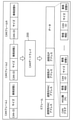
車両1のネットワークシステム3は、制御装置、センサ、アクチュエータ、ユーザインタフェース装置等の各種機器が搭載された車両1におけるネットワーク通信システムである。ネットワークシステム3は、第1ネットワーク10と第2ネットワーク20とを有する。車両1は、移動体の一例である。第1ネットワーク10は、Ethernet(登録商標)プロトコルに従ってEthernet(登録商標)フレーム(以下、「Eフレーム」という)の伝送が行われるEthernet(登録商標)のネットワークである。第2ネットワーク20は、CANプロトコルに従ってバスでデータフレーム(CANフレーム)等の伝送が行われるCANのネットワークである。
The
図1に示すように、ネットワークシステム3は、セントラルゲートウェイ400と、テレマティクスコントロールユニット410と、診断ポート420と、自動運転DCU(Domain Control Unit)100と、自動運転ECU110と、カメラ120と、LIDAR130と、ダイナミックマップECU140と、インフォテインメントDCU300と、IVI(In-Vehicle Infotainment)310と、CANゲートウェイ200と、エンジンECU210と、ステアリングECU220と、ブレーキECU230と、ウィンドウECU240と、第1伝送路11と、第2伝送路21とを含んで構成される。第1伝送路11は、第1ネットワーク10の伝送路であり、例えばEthernet(登録商標)ケーブルである。第2伝送路21は、第2ネットワーク20の伝送路であり、例えばCANバスである。
As shown in FIG. 1, the
なお、ネットワークシステム3には、上記の各ECU110、140、210、220、230、240または各DCU100、300の他にもいくつものECUまたはDCUが含まれてもよい。例えば、第2伝送路21には、各ECU210、220、230、240以外にも、図示しないECUが接続されてもよい。
The
各ECU110、140、210、220、230、240または各DCU100、300は、例えば、プロセッサ(マイクロプロセッサ)、メモリ等のデジタル回路、アナログ回路、通信回路等を含む装置である。メモリは、ROM、RAM等であり、プロセッサにより実行されるプログラム(ソフトウェアとしてのコンピュータプログラム)を記憶することができる。メモリとして、不揮発性メモリを含んでもよい。例えばプロセッサが、プログラム(コンピュータプログラム)に従って動作することにより、ECUは各種機能を実現することになる。なお、コンピュータプログラムは、所定の機能を達成するために、プロセッサに対する指令を示す命令コードが複数個組み合わされて構成されたものである。
Each
各ECU210、220、230、240は、CANプロトコルに従ってフレームの授受を行う。各ECU210、220、230、240は、それぞれエンジン、ステアリング、ブレーキ、ウィンドウ開閉センサといった機器に接続されており、その機器の状態を取得し、例えば周期的に、状態を表すデータフレームを、第2伝送路21等で構成される第2ネットワーク20に送信している。また、各ECU210、220、230、240は、第2ネットワーク20を構成する第2伝送路21からデータフレームを受信して、データフレームを解釈し、受信すべきCAN-IDを有するデータフレームか否かの判別を行う。そして、各ECU210、220、230、240は、判別の結果、必要に応じてデータフレーム内のデータ(データフィールドの内容)に従って、当該ECUに接続されている機器の制御を行ってもよいし、必要に応じてデータフレームを生成して送信してもよい。
Each
各ECU110、140または各DCU100、300は、Ethernet(登録商標)プロトコルに従ってEフレームの送信又は受信を行う。各DCU100、300は、それぞれIVI310、自動運転ECU110、カメラ120、LIDAR130、ダイナミックマップECU140といった機器に接続されており、その機器から取得した情報に基づく処理を行う。また、各DCU100、300は、必要に応じて接続されている機器を制御してもよいし、必要に応じて他のECUへの情報の送信を行ってもよい。
Each
セントラルゲートウェイ400には、テレマティクスコントロールユニット410と診断ポート420と、自動運転DCU100と、CANゲートウェイ200と、インフォテインメントDCU300が、第1伝送路11で接続される。セントラルゲートウェイ400は、例えば、メモリ等のデジタル回路、アナログ回路、通信回路等を含む。
The
テレマティクスコントロールユニット410は、車両1が外部ネットワーク30上にあるサーバ2と通信するユニットである。テレマティクスコントロールユニット410は、例えば、第3世代移動通信システム(3G)、第4世代移動通信システム(4G)、または、LTE(登録商標)などのような移動通信システムで利用される通信規格に適合した無線通信インタフェースを有していてもよいし、IEEE802.11a、b、g、n規格に適合した無線LAN(Local Area Network)インタフェースを有していてもよい。つまり、外部ネットワーク30は、携帯電話通信網、Wi-Fiなどである。サーバ2は、例えば車両1のECUに対して情報を提供する機能等を有するコンピュータである。
The
診断ポート420は、ディーラが車両1の故障診断に使うためのポートであり、診断用のコマンドの送受信に利用されるポートである。
The
自動運転DCU100は、自動運転ECU110と、カメラ120と、LIDAR130と、ダイナミックマップECU140と、第1伝送路11で接続されている。
The
自動運転ECU110は、車両1の運転を制御する制御コマンドを生成する。具体的には、自動運転ECU110は、車輪の操舵を行うステアリング、車輪を回転駆動させるエンジン、モータなどの動力源、車輪の制動するブレーキなどを制御する制御コマンドを生成する。つまり、制御コマンドは、進む(つまり、走行する)、曲がる、止まるの少なくとも1つを車両1に実行させる制御コマンドである。自動運転ECU110は、生成した制御コマンドを第2ネットワーク20に送信する。
The
カメラ120は、車外の状況、つまり、車両1の周囲を撮影するカメラである。カメラ120は、例えば、車両1の車体の外側に配置されていてもよい。
The
LIDAR130は、車外の障害物を感知するためのセンサである。LIDAR130は、例えば、車両1の水平方向において360度全方位、および、垂直方向において所定の角度(例えば30度)の角度範囲の検出範囲にある物体との距離を検出するレーザセンサである。LIDAR130は、車両1の周囲にレーザを発し、周囲の物体に反射されたレーザを検知することで、LIDAR130から物体までの距離を計測する。
The
ダイナミックマップECU140は、ダイナミックマップに用いるデータを受信し、受信したデータを用いてダイナミックマップを復号するための電子制御ユニットである。復号されたダイナミックマップは、例えば、自動運転ECU110による自動運転の制御に用いられる。
The
CANゲートウェイ200は、第2ネットワーク20および第1ネットワーク10に接続されているゲートウェイである。第2ネットワーク20は、本実施の形態では、エンジンECU210、ステアリングECU220、ブレーキECU230の制御系バスと、ウィンドウ開閉を制御するウィンドウECU240が接続されるボディ系バスとの2本のCANバスを備えている。CANゲートウェイ200は、プロセッサ、メモリ等のデジタル回路、アナログ回路、通信回路等を含む。CANゲートウェイ200は、2つの伝送路11、21のうち、一の伝送路から受信したフレームを他の伝送路に転送(または中継)する機能を有する。CANゲートウェイ200によるフレームの転送は、フレームに係るデータの中継である。CANゲートウェイ200は、フレームの転送において、転送先の伝送路で用いられる通信プロトコルに対応した、通信方式、フレームフォーマット等の変換が行われてもよい。また、CANゲートウェイ200は、伝送路間でのフレームの転送として、1以上の伝送路から受信した1以上のフレームに対応して、1以上のフレームの、1以上複数の伝送路への送信を行ってもよい。
The
インフォテインメントDCU300は、IVI310と、第1伝送路11で接続されており、情報系ネットワークのドメイン管理を行う。IVI310は、ディスプレイを備え、映像、音声等の再生といったマルチメディア機能を有する装置である。
The infotainment DCU300 is connected to the IVI310 by the
図2は、第2ネットワークで送受信されるデータフレーム(CANフレーム)のフォーマットを示す図である。 FIG. 2 is a diagram showing a format of a data frame (CAN frame) transmitted / received on the second network.
第2ネットワーク20では、各ECU210、220、230、240等がCANプロトコルに従ってフレームの授受を行う。CANプロトコルにおけるフレームには、データフレーム、リモートフレーム、オーバーロードフレーム及びエラーフレームがあるが、ここでは、主にデータフレームに注目して説明する。
In the
図2の(a)は標準フォーマットである。標準フォーマットにおいては、データフレームは、SOF(Start Of Frame)、ID(CAN-ID)、RTR(Remote Transmission Request)、IDE(Identifier Extension)、予約ビット「r」、サイズ、データ、CRC(Cyclic Redundancy Check)シーケンス、CRCデリミタ「DEL」、ACK(Acknowledgement)スロット、ACKデリミタ「DEL」、及び、EOF(End Of Frame)で構成される。ここで、IDフィールドの内容としてのID(CAN-ID)は、データの種類を示す識別子であり、メッセージIDとも称される。つまり、CANフレームは、種類毎に異なる識別子を有する。なお、CANでは、複数のノードが同時に送信を開始した場合、このCAN-IDが小さい値を持つフレームを優先する通信調停がなされる。サイズは、後続するデータフィールド(データ)の長さを示すDLC(Data Length Code)である。データ(データフィールドの内容)の仕様については、CANプロトコルで規定されておらず、ネットワークシステム3において定められる。従って、車両の車種、製造者(製造メーカ)等に依存した仕様となり得る。
FIG. 2A is a standard format. In the standard format, the data frame is SOF (Start Of Frame), ID (CAN-ID), RTR (Remote Transmission Request), IDE (Identifier Extension), reservation bit "r", size, data, CRC (Cyclic Redundancy). Check) sequence, CRC delimiter "DEL", ACK (Acknowledgement) slot, ACK delimiter "DEL", and EOF (End Of Frame). Here, the ID (CAN-ID) as the content of the ID field is an identifier indicating the type of data, and is also referred to as a message ID. That is, the CAN frame has a different identifier for each type. In CAN, when a plurality of nodes start transmission at the same time, communication arbitration is performed in which a frame having a small value of CAN-ID is prioritized. The size is a DLC (Data Length Code) indicating the length of a subsequent data field (data). The specifications of data (contents of data fields) are not specified in the CAN protocol, but are specified in the
図2の(b)は拡張フォーマットである。本実施の形態では第2ネットワーク20で標準フォーマットが用いられることとして説明するが、第1ネットワーク10において拡張フォーマットが用いられる場合には、11ビットのIDフィールドのベースID(CAN-IDの一部)と、18ビットの拡張ID(CAN-IDの残部)とを合わせた29ビットをCAN-IDと扱えばよい。
FIG. 2B is an extended format. In the present embodiment, the standard format is used in the
図3は、第1ネットワークで送受信されるEフレームのフォーマットを示す図である。 FIG. 3 is a diagram showing a format of E frames transmitted / received on the first network.
同図に示すように、Eフレームは、主たる伝送内容であるデータを格納するEthernet(登録商標)ペイロード(「Eペイロード」とも言う。)と、Ethernet(登録商標)ヘッダ(「Eヘッダ」とも言う。)とにより構成される。Eヘッダには、宛先MACアドレスおよび送信元MACアドレスが含まれる。また、Eペイロードには、IPヘッダ、TCP/UDPヘッダおよびデータが含まれる。IPヘッダには、送信元IPアドレスおよび送信先アドレスが含まれる。なお、図3では、IPヘッダは、「IP v4ヘッダ」と表記している。TCP/UDPヘッダは、TCPヘッダまたはUDPヘッダを示し、TCP/UDPヘッダには、送信元ポート番号および送信先ポート番号が含まれる。 As shown in the figure, the E-frame has an Ethernet (registered trademark) payload (also referred to as “E-payload”) and an Ethernet (registered trademark) header (also referred to as “E-header”) for storing data which is the main transmission content. .) And. The E header contains the destination MAC address and the source MAC address. Further, the E payload includes an IP header, a TCP / UDP header, and data. The IP header contains a source IP address and a destination address. In addition, in FIG. 3, the IP header is described as “IP v4 header”. The TCP / UDP header indicates a TCP header or a UDP header, and the TCP / UDP header includes a source port number and a destination port number.
ネットワークシステム3におけるCANゲートウェイ200は、CANバスから受信したCANフレームを第1ネットワーク10へと転送する際に、複数のCANフレーム情報を含むEフレームを送信する。CANフレーム情報は、CANバスで伝送されたCANフレームから抽出した情報であり、少なくともデータフィールドの内容(データ)を含む。CANフレーム情報は、例えばCAN-ID及びサイズを含んでもよい。
The
図3に示すEフレームのペイロード内のデータ構成例を図4に示す。図4の例では、CANフレーム情報は、CAN-ID、サイズ及びデータで構成される。図4のメッセージ数(MSG数)は、CANフレーム情報の個数を示す。なお、メッセージ数の代わりに、CANフレーム情報の全体のデータ量等を示す情報を用いてもよい。また、CANフラグは、Eフレームが第2ネットワーク20から伝送される情報(つまりCANフレーム情報)を含むか否かを識別するための識別フラグであり、EフレームのEペイロードにCANフレーム情報を含む場合においてONにされ、それ以外の場合にOFF(つまりONと相反する情報を示す値)にされるフラグである。図4の例では、EフレームのEペイロードの先頭にCANフラグを配置する例を示しているがこれは一例に過ぎない。図4の例のような複数のCANフレーム情報をEフレームのEペイロードに含ませることで、例えば、伝送効率が高まり得る。 FIG. 4 shows an example of data composition in the payload of the E frame shown in FIG. In the example of FIG. 4, the CAN frame information is composed of CAN-ID, size and data. The number of messages (number of MSGs) in FIG. 4 indicates the number of CAN frame information. In addition, instead of the number of messages, information indicating the total amount of data of CAN frame information and the like may be used. Further, the CAN flag is an identification flag for identifying whether or not the E frame includes information transmitted from the second network 20 (that is, CAN frame information), and the E payload of the E frame includes CAN frame information. It is a flag that is turned on in some cases and turned off in other cases (that is, a value indicating information contradictory to ON). In the example of FIG. 4, an example in which the CAN flag is placed at the beginning of the E payload of the E frame is shown, but this is only an example. By including a plurality of CAN frame information as in the example of FIG. 4 in the E payload of the E frame, for example, the transmission efficiency can be improved.
図5は、CANゲートウェイの機能構成の一例を示すブロック図である。 FIG. 5 is a block diagram showing an example of the functional configuration of the CAN gateway.
同図に示すように、CANゲートウェイ200は、Ethernet(登録商標)送受信部201(以下、「E送受信部201」と言う。)と、CAN送受信部202a、202bと、転送制御部203と、転送ルール保持部204とを備える。これらの各構成要素は、CANゲートウェイ200における通信回路、メモリ、デジタル回路、メモリに格納されたプログラムを実行するプロセッサ等により実現される。
As shown in the figure, the
E送受信部201は、第1ネットワーク10を構成する第1伝送路11に接続される通信回路等である。E送受信部201は、第1伝送路11からEフレームを受信する。また、E送受信部201は、第1伝送路11にEフレームを送信する。
The E transmission /
CAN送受信部202aは、第2ネットワーク20を構成するCANバス21aに接続される通信回路等である。CAN送受信部202aは、CANバス21aからCANフレームを逐次受信する。また、CAN送受信部202aは、CANバス21aにCANフレームを送信する。
The CAN transmission /
CAN送受信部202bは、第2ネットワーク20を構成するCANバス21bに接続される通信回路等である。CAN送受信部202bは、CANバス21bからCANフレームを逐次受信する。CAN送受信部202bは、CANバス21bにCANフレームを送信する。
The CAN transmission /
転送ルール保持部204は、メモリ等の記憶媒体で実現され、フレームの転送の条件等を定める基準情報を保持する。基準情報は、例えば、転送対象のCAN-ID及び転送元のバスと宛先(MACアドレス等)とを対応付けた転送ルール情報、優先転送対象のCAN-ID及び転送元のバスと宛先とを対応付けた優先転送リスト等である。
The transfer
転送制御部203は、例えばプログラムを実行するプロセッサ等で実現され、受信したフレームを転送すべきか否か判定し判定結果に応じて転送に係る制御を行う。この転送に係る制御は、例えば、逐次受信した複数のCANフレームに基づいて、複数のCANフレーム情報をペイロードとして含ませたEフレームを、E送受信部201に第1伝送路11へと送信させる制御である。
The
図6は、実施の形態1に係るCANゲートウェイ200が受信した複数のCANフレーム(CANフレーム1~N)に基づいてEフレームを送信するイメージを示す図である。
FIG. 6 is a diagram showing an image of transmitting an E frame based on a plurality of CAN frames (CAN frames 1 to N) received by the
同図に示すように、CANゲートウェイ200はフレームを転送する際に、フレームの構成を変更する。送信されるEフレームのペイロードには、例えば予め定められた数であるN個のCANフレーム情報が含まれる。そのN個のCANフレーム情報のデータは、受信されたN個のCANフレームのデータフィールドの内容(データ)等である。受信され転送待ちになっているCANフレームの内容は、例えば、CANゲートウェイ200が備えるメモリ等の記憶媒体(バッファ)に格納される。図6のN個のCANフレーム情報を含むEフレームは、例えばセントラルゲートウェイ400を経由して、宛先のECUまたはDCU(例えばインフォテインメントDCU300)に受信されることになる。Eフレームのヘッダの送信元MACアドレスとして、CANゲートウェイ200のMACアドレスが設定され、EフレームのEペイロードには、CANフレーム情報が含まれることを示す、ONにしたCANフラグが設定される。Eフレームの宛先MACアドレスとしては、転送ルール保持部204が保持する転送ルール情報等に従って、宛先となるECUまたはDCUのMACアドレスが設定される。
As shown in the figure, the
なお、本実施の形態では、CANゲートウェイ200は、自動運転の制御コマンドの異常を検知するために、第2ネットワーク20に流れる車両状態を示す状態情報を含むN個のCANフレームを結合して1つのEフレームに変換する。本実施の形態では、CANフレームに含まれる車両状態は、現在の車速、ステアリングの角度、シフトポジションなどである。車両状態は、移動体の状態の一例である。
In the present embodiment, the
転送制御部203は、判定等の結果に応じて一定条件下でE送受信部201、CAN送受信部202a、202bを制御して、フレームの送信を行わせる。転送制御部203は、CAN送受信部202a、202bにより受信されたCANフレームについて、CAN-IDに基づいてそのCANフレームのデータが第1ネットワーク10に送信されるべきか否かを判定する。この判定は、例えば、予め定められた、CAN-IDに関する基準情報に従って行われる。また、転送制御部203は、CANフレームのデータの宛先を、基準情報に従って選定する。CANフレームが第1ネットワーク10に送信されるべきか否かの判定及びCANフレームのデータを含むフレーム(Eフレーム或いはCANフレーム)の宛先の選定は、例えば、データが第1ネットワーク10に送信されるべき1つ以上のCANフレームのCAN-ID等を示す転送ルール情報を用いて行われる。
The
図7は、自動運転DCU100の機能構成の一例を示すブロック図である。 FIG. 7 is a block diagram showing an example of the functional configuration of the automatic operation DCU100.
同図に示すように、自動運転DCU100は、第1通信部101aと、第2通信部101bと、スイッチ処理部102と、スイッチルール保持部103と、異常検知処理部104と、異常検知ルール保持部105とを有する。自動運転DCU100は、異常検知装置の一例である。
As shown in the figure, the automatic operation DCU100 has a
第1通信部101aは、本実施の形態では1つのEthernet(登録商標)ポート(ポートP1)を備える。ポートP1は、セントラルゲートウェイ400と第1伝送路11で接続されている。つまり、第1通信部101aは、セントラルゲートウェイ400との間でデータの送受信を行う。つまり、第1通信部101aは、CANフレームがデータとして格納されたEフレームを受信する。これにより、第1通信部101aは、CANフレームを受信することで、CANフレームに含まれる状態情報を受信する。
The
第2通信部101bは、本実施の形態では4つのEthernet(登録商標)ポート(ポートP2~P5)を備える。ポートP2~P5は、それぞれ、カメラ120、LIDAR130、ダイナミックマップECU140および自動運転ECU110と第1伝送路11で接続されている。つまり、第2通信部101bは、第1ネットワーク10の通信プロトコル(つまりEthernet(登録商標)プロトコル)による第1フレーム(つまりEフレーム)を送受信する。また、第2通信部101bは、ポートP1でのEフレームの送受信を行う第1通信部101aを含む。
The
スイッチ処理部102は、第2通信部101bにより受信されたEフレームを、スイッチルール保持部103が保持するルールに基づき、適切な転送先に転送する処理を行う。
The
図8は、スイッチルール保持部103が保持するスイッチルールの一例を示す図である。
FIG. 8 is a diagram showing an example of a switch rule held by the switch
同図に示すように、スイッチルールは、入力ポート、送信元IPアドレス、送信元MACアドレス、出力ポート、送信先IPアドレス、送信先MACアドレスから構成される。本実施の形態のおけるスイッチルールは、正常なEフレームの正しい転送先を示すホワイトリストである。スイッチルールでは、例えば、ポートP1において、CANゲートウェイ200からのEフレームがセントラルゲートウェイ400を介して受信され、ポートP5に接続される自動運転ECU110へ転送する経路が許可されていることを示している。この場合、入力ポートとなるポートP1で受信するEフレームの送信元MACアドレスはセントラルゲートウェイ400のMACアドレスが設定されており、送信元IPアドレスはCANゲートウェイ200のIPアドレスが設定されている。一方、出力ポートとなるポート5に接続されている送信先IPアドレスおよび送信先MACアドレスには、自動運転ECUのIPアドレスおよびMACアドレスが設定されている。
As shown in the figure, the switch rule is composed of an input port, a source IP address, a source MAC address, an output port, a destination IP address, and a destination MAC address. The switch rule in this embodiment is a white list indicating the correct transfer destination of a normal E frame. The switch rule indicates that, for example, at port P1, the route in which the E frame from the
また、図8のスイッチルールでは、ポート2に接続されているカメラ120、ポート3に接続されているLIDAR130、および、ポート4に接続されているダイナミックマップECU140は、ポート5に接続される自動運転ECU110への転送が許可されていることを示している。また、ポート5に接続される自動運転ECU110からのEフレームは、CANゲートウェイ200に送信する必要があるので、送信先IPにはCANゲートウェイ200のIPアドレスが設定され、送信先MACアドレスにはセントラルゲートウェイのMACアドレスが設定されている。
Further, in the switch rule of FIG. 8, the
なお、スイッチルールでは、入力または出力における送信元および送信先には、IPアドレスおよびMACアドレスで定義されているが、これに限定されない。例えば、IPアドレスだけが定義されていてもよいし、MACアドレスだけが定義されていてもよい。また、スイッチルールには、IPアドレスまたはMACアドレス以外の送信元または送信先が識別できる情報が定義されていてもよいし、サービスポート番号が定義されてもよい。これにより、入力または出力における送信元および送信先を、スイッチルールで許可されている経路に制限することができる。 In the switch rule, the source and destination in the input or output are defined by the IP address and the MAC address, but the present invention is not limited to this. For example, only the IP address may be defined, or only the MAC address may be defined. Further, the switch rule may define information other than the IP address or MAC address that can identify the source or destination, or may define the service port number. This allows the source and destination in the input or output to be restricted to the routes allowed by the switch rule.
図8のスイッチルールは、ホワイトリストにより定義されたが、ブラックリストにより定義されてもよい。また、図8で示したスイッチルールは、一部であり、これが全てではない。つまり、スイッチルールは、必要な経路が網羅されるように設定されるものとする。 The switch rule of FIG. 8 is defined by a whitelist, but may be defined by a blacklist. Also, the switch rules shown in FIG. 8 are partial, not all. That is, the switch rule shall be set so as to cover the necessary routes.
異常検知処理部104は、CANゲートウェイ200経由で第2ネットワーク20から第1通信部101aにより受信された車両1の状態情報と、異常検知ルール保持部105に保持されている異常検知ルールとを参照して、第2通信部101bにおいて受信されたEフレームに含まれる制御コマンドが異常であるか否かを検知する。制御コマンドは、例えば、自動運転ECU110が生成する自動運転制御コマンドである。異常検知処理部104は、制御コマンドが正常であると判断した場合、セントラルゲートウェイ400からCANゲートウェイ200を介して当該制御コマンドを第2通信部101bに第2ネットワーク20へ送信させる。異常検知処理部104は、制御コマンドが異常であると判断した場合、第2通信部101bによる制御コマンドの第2ネットワーク20への転送を禁止する。
The abnormality
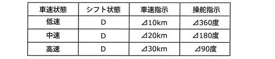
図9は、実施の形態1に係る自動運転DCU100の異常検知ルール保持部105が保持する異常検知ルールの一例を示す図である。異常検知ルールは、第2ネットワーク20から取得される車両状態をベースにしたEthernet(登録商標)における自動運転制御が許可されるルールである。つまり、異常検知ルールは、車両の複数の状態のそれぞれにおいて許可される制御コマンドを示す第1ルールを含む。
FIG. 9 is a diagram showing an example of an abnormality detection rule held by the abnormality detection
同図に示すように、異常検知ルールの第1ルールは、車両1の車速状態およびシフト状態に応じて許可される、車速指示および操舵指示の組み合わせを示す。なお、車速状態とは、車両1の走行中の速度を示し、例えば、0km/h以上30km/h未満の速度範囲を低速、30km/h以上60km/h未満の速度を中速、60km/以上100km/h以下を高速とそれぞれ定義したものである。また、シフト状態とは、シフトポジションを示し、例えばパーキング(P)、リバース(R)、ニュートラル(N)、ドライブ(D)などである。車速指示は、現在の車速から許可される増減の速度値を示す。また、操舵指示は、現在のステアリングの旋回角度から許可される増減の角度を示す。
As shown in the figure, the first rule of the abnormality detection rule shows a combination of a vehicle speed instruction and a steering instruction permitted according to the vehicle speed state and the shift state of the
第1ルールでは、例えば、車速状態が低速であり、かつ、シフト状態がドライブ(D)のときに、自動運転制御における車速指示が、状態情報が示す現時点の車速から10km/hの範囲であれば、車速を増減することが許可されている。また、第1ルールでは、例えば、車速状態が中速であり、かつ、シフト状態がドライブ(D)のときに、自動運転制御における車速指示が、状態情報が示す現時点の車速から20km/hの範囲であれば、車速を増減することが許可されている。また、第1ルールでは、例えば、車速状態が高速であり、かつ、シフト状態がドライブ(D)のときに、自動運転制御における車速指示が、状態情報が示す現時点の車速から30km/hの範囲であれば、車速を増減することが許可されている。 In the first rule, for example, when the vehicle speed state is low and the shift state is drive (D), the vehicle speed instruction in the automatic driving control is in the range of 10 km / h from the current vehicle speed indicated by the state information. For example, it is permitted to increase or decrease the vehicle speed. Further, in the first rule, for example, when the vehicle speed state is medium speed and the shift state is drive (D), the vehicle speed instruction in the automatic driving control is 20 km / h from the current vehicle speed indicated by the state information. If it is within the range, it is allowed to increase or decrease the vehicle speed. Further, in the first rule, for example, when the vehicle speed state is high speed and the shift state is drive (D), the vehicle speed instruction in the automatic driving control is in the range of 30 km / h from the current vehicle speed indicated by the state information. If so, it is permitted to increase or decrease the vehicle speed.
第1ルールでは、操舵指示のステアリングの旋回指示角度においても車速と同様に定義されている。つまり、第1ルールでは、例えば、車速状態が低速であり、かつ、シフト状態がドライブ(D)のときに、自動運転制御における操舵指示が、状態情報が示す現時点のステアリングの角度から左右360度以内であれば、ステアリングの角度を変更することが許可されている。また、第1ルールでは、例えば、車速状態が中速であり、かつ、シフト状態がドライブ(D)のときに、自動運転制御における操舵指示が、状態情報が示す現時点のステアリングの角度から左右180度以内であれば、ステアリングの角度を変更することが許可されている。また、第1ルールでは、例えば、車速状態が高速であり、かつ、シフト状態がドライブ(D)のときに、自動運転制御における操舵指示が、状態情報が示す現時点のステアリングの角度から左右90度以内であれば、ステアリングの角度を変更することが許可されている。 In the first rule, the steering turning instruction angle of the steering instruction is defined in the same manner as the vehicle speed. That is, in the first rule, for example, when the vehicle speed state is low and the shift state is drive (D), the steering instruction in the automatic driving control is 360 degrees to the left and right from the current steering angle indicated by the state information. If it is within the range, it is allowed to change the steering angle. Further, in the first rule, for example, when the vehicle speed state is medium speed and the shift state is drive (D), the steering instruction in the automatic driving control is 180 left and right from the current steering angle indicated by the state information. It is allowed to change the steering angle within degrees. Further, in the first rule, for example, when the vehicle speed state is high speed and the shift state is drive (D), the steering instruction in the automatic driving control is 90 degrees to the left and right from the current steering angle indicated by the state information. If it is within the range, it is allowed to change the steering angle.
異常検知処理部104は、状態情報が示す車両1の状態が、制御コマンドが第1ルールにおいて対応付けられている状態に含まれない場合、制御コマンドが異常であることを検知する。つまり、異常検知処理部104は、例えば、車両状態に第1ルールにおいて対応付けられている、許可される範囲の車速の増減を超える車速指示、または、許可される範囲のステアリングの角度を超える操舵指示を含む制御コマンドが第2通信部101bにより受信された場合、当該制御コマンドが異常であることを検知し、第1通信部101aによる第2ネットワーク20への当該制御コマンドの転送を禁止する。
The abnormality
次に、実施の形態1に係る車両1に搭載されるネットワークシステム3の動作について説明する。
Next, the operation of the
図10および図11は、実施の形態1に係るネットワークシステム3における異常検知方法の一例を示すシーケンス図である。
10 and 11 are sequence diagrams showing an example of an abnormality detection method in the
まず、自動運転DCU100は、自動運転ECU110に対して、自動運転モードを有効な状態にする(S100)。例えば、ユーザからの自動運転モードをONにする入力を受け付けた場合、自動運転DCU100は、自動運転モードを有効な状態にする。
First, the
CANゲートウェイ200は、CANゲートウェイ200に接続されている各ECU210、220、230、240から車両1の状態情報を含むCANフレームを受信し、図6に示したように、車両1の状態情報のCANフレームを含んだEフレームを生成する(S101)。
The
CANゲートウェイ200は、車両1の状態情報のCANフレームを含むEフレームをセントラルゲートウェイ400に送信する(S102)。
The
セントラルゲートウェイ400は、ステップS102において受信したEフレームを自動運転DCU100に送信する(S103)。
The
自動運転DCU100では、第2通信部101bがカメラ120により撮影された映像を示す映像情報、LIDAR130により検出された物体までの距離を示す情報に基づく障害物情報、ダイナミックマップECU140により得られる地図情報を、それぞれカメラ120、LIDAR130およびダイナミックマップECU140から受信する(S104)。
In the automatic operation DCU100, the
自動運転DCU100では、スイッチ処理部102が、スイッチルール保持部103のスイッチルールを参照して、正しい経路で情報を受信したか否かを判定する(S105)。
In the
これにより、自動運転DCU100では、ステップS104において第2通信部101bは、カメラ120、LIDAR130、ダイナミックマップECU140から受信した映像情報、障害物情報および地図情報などの情報のうち、正しい経路で受信したとスイッチ処理部102により判定された情報を、自動運転ECU110に転送する(S106)。
As a result, in the automatic operation DCU100, in step S104, the
自動運転ECU110は、ステップS106で受信した映像情報、障害物情報および地図情報などの情報に基づいて、自動運転のための制御コマンドを生成する(S107)。ここでは、自動運転ECU110は、まず制御系CANバスに伝えるためのCANフレームを生成し、それらCANフレームをEフレームのデータ領域に格納したEフレームを生成する。生成されたEフレームは、自動運転のための制御コマンドである。
The
自動運転ECU110は、自動運転のための制御コマンドを自動運転DCU100に送信する(S108)。
The
自動運転DCU100では、異常検知処理部104は、異常検知ルール保持部105が保持する異常検知ルールを参照する(S109)。ここで参照するルールは、図9で示した第1ルールである。
In the
自動運転DCU100では、異常検知処理部104は、異常検知ルールに加えて、さらにS103で受信した車両1の状態情報のCANフレームを含んだEフレームを参照し、ステップS108によって第2通信部101bが受信した制御コマンドが異常であるか否かを判定する(S110)。異常検知処理部104は、制御コマンドが異常であると判定した場合(ステップS110で異常)、ステップS111へ処理を移す。一方で、異常検知処理部104は、制御コマンドが正常であると判定した場合(ステップS110で正常)、ステップS120へ処理を移す。
In the automatic driving DCU100, the abnormality
自動運転DCU100では、異常検知処理部104は、制御コマンドが異常であると判定したため、サーバ2またはIVI310に異常があったことを含む情報を、第2通信部101bを用いて通知する(S111)。これにより、ドライバ、または、リモートで監視しているセキュリティ監視サービスの事業者は、車両1に自動運転において異常が発生したことを把握することが可能になる。なお、この場合、異常検知処理部104は、制御コマンドをセントラルゲートウェイ400に送信しない。つまり、異常検知処理部104は、この場合、異常であると判定した制御コマンドを、セントラルゲートウェイ400およびCANゲートウェイ200を介して第2ネットワーク20に転送することを禁止する。
In the automatic operation DCU100, since the abnormality
自動運転DCU100では、異常検知処理部104は、自動運転ECU110に、自動運転を終了させる終了指示を、第2通信部101bを用いて送信する(S112)。
In the
自動運転ECU110は、ステップS112において送信された終了指示を受信した場合、自動運転モードを終了する(S113)。なお、自動運転ECU110は、自動運転モードを終了した後に、手動運転モードに切り替えてもよい。
When the
ステップS110において、制御コマンドが正常であると判定された場合(S110で正常)、異常検知処理部104は、第2通信部101bを用いて、自動運転のための制御コマンドをセントラルゲートウェイ400に送信する(S120)。
When it is determined in step S110 that the control command is normal (normal in S110), the abnormality
セントラルゲートウェイ400は、ステップS120において送信された自動運転制御コマンドをCANゲートウェイ200に転送する(S121)。
The
CANゲートウェイ200は、ステップS121で受信したEフレームの自動運転の制御コマンドをCANフレームに変換する(S122)。
The
CANゲートウェイ200は、ステップS122で変換したCANフレームを第2ネットワーク20に送信する(S123)。これにより、制御系CANバスに接続されるエンジンECU210、ステアリングECU220またはブレーキECU230は、CANフレームの自動運転の制御コマンドを受信し、受信した制御コマンドに応じた制御を実行することで自動運転制御を行う。
The
本実施の形態に係る異常検知装置は、車両1に搭載され、通信プロトコルが互いに異なる第1ネットワーク10および第2ネットワーク20を有するネットワークシステム3における異常を検知する異常検知装置である。自動運転DCU100は、第1通信部101aと、第2通信部101bと、異常検知ルール保持部105と、異常検知処理部104とを備える。第1通信部101aは、第2ネットワーク20から取得される車両1の状態を示す状態情報を受信する。第2通信部101bは、第1ネットワーク10の通信プロトコルによるEフレームを送受信する。異常検知ルール保持部105は、異常検知ルールを保持する。異常検知処理部104は、状態情報と、異常検知ルールとを参照して、第2通信部101bにおいて受信されたEフレームに含まれる制御コマンドが異常であるか否かを検知する。異常検知処理部104は、制御コマンドが異常であることを検知した場合、当該制御コマンドの転送を禁止する。
The abnormality detection device according to the present embodiment is an abnormality detection device mounted on a
これによれば、異常検知装置は、第2ネットワーク20から得られる車両1の状態情報と、異常検知ルールとに基づき、生成された自動運転の制御コマンドが異常であるか否かを検知する。そして、異常検知装置は、異常があることを検知された制御コマンドの転送を禁止する。このため、例えば第1ネットワーク10に接続される機器に脆弱性があって、第1ネットワーク10経由で攻撃をされた場合であっても、異常検知装置は、不正な自動運転の制御を防止することが可能となる。
According to this, the abnormality detection device detects whether or not the generated automatic driving control command is abnormal based on the state information of the
また、本実施の形態に係る異常検知装置において、異常検知ルールは、車両1の異なる複数の状態のそれぞれにおいて許可される制御コマンドを示す第1ルールを含む。異常検知処理部104は、状態情報が示す車両1の状態が、制御コマンドが第1ルールにおいて対応付けられている状態に含まれない場合、制御コマンドが異常であることを検知する。このため、例えば、現時点の車速、ステアリングの操舵角度、シフトポジションなどの車両状態に基づいて制御コマンドの異常を検知することが可能となる。
Further, in the abnormality detection device according to the present embodiment, the abnormality detection rule includes a first rule indicating a control command permitted in each of a plurality of different states of the
また、本実施の形態に係る異常検知装置において、制御コマンドは、進む、曲がる、および、止まるの少なくとも1つを車両1に実行させる制御コマンドである。このため、異常検知装置は、例えば、走行中の急ハンドル、急ブレーキまたは急加速、停車中の急発信など、自動運転における制御コマンドの異常を検知し、安全な運転環境を提供することが可能となる。
Further, in the abnormality detection device according to the present embodiment, the control command is a control command for causing the
また、本実施の形態に係る異常検知装置において、第1通信部101aは、CANフレームがデータとして格納されたEフレームである第1フレームを受信する。また、第2通信部101bは、第1通信部101aを含む。これによれば、異常検知装置は、Eフレームに変換されたCANフレームを受信するため、Ethernet(登録商標)上の機器でCANフレームの異常検知が可能となる。
Further, in the abnormality detection device according to the present embodiment, the
(実施の形態2)
次に実施の形態2について説明する。実施の形態2に係る異常検知装置としての自動運転DCU100は、実施の形態1に係る自動運転DCU100とほぼ同等であるので、異なる部分のみを説明する。実施の形態2では、自動運転DCU100にて、CANフレームの異常検知も行う点が実施の形態1に係る自動運転DCU100と異なる。
(Embodiment 2)
Next, the second embodiment will be described. Since the automatic operation DCU100 as the abnormality detection device according to the second embodiment is substantially the same as the automatic operation DCU100 according to the first embodiment, only different parts will be described. The second embodiment is different from the
図12は、実施の形態2に係るCANゲートウェイ200が受信した複数のCANフレームに基づいてEフレームを送信するイメージを示す図である。
FIG. 12 is a diagram showing an image of transmitting an E frame based on a plurality of CAN frames received by the
本実施の形態では、自動運転DCU100は、CANフレームの周期を確認してCANの異常検知を行う。図12に示すように、CANゲートウェイ200は、複数のCANフレームを受信し、受信した複数のCANフレームのそれぞれについて、当該CANフレームを受信した受信時刻を当該CANフレームに付与する。つまり、CANゲートウェイ200は、N個の受信時刻が付与されたCANフレームをEフレームのデータ領域に格納することでEフレームを生成する。実施の形態1と同様に、CANゲートウェイ200が、Eフレーム化するCANフレームに含まれる車両1の状態情報は、車速、ステアリングの角度またはシフトポジションなどである。
In the present embodiment, the automatic operation DCU100 confirms the period of the CAN frame and detects the abnormality of the CAN. As shown in FIG. 12, the
自動運転DCU100の第2通信部101bは、図12の構成のEフレームを受信するため、複数のCANフレームと、複数のCANフレームのそれぞれが例えばCANゲートウェイ200などの機器により受信された時刻である受信時刻とがデータとして格納されたEフレームを受信することとなる。
Since the
図13は、実施の形態2に係る自動運転DCU100の異常検知ルール保持部105が保持する異常検知ルールの一例を示す図である。図13に示す異常検知ルールは、CANフレームが異常であるか否かを検知するための第2ルールの一例である。
FIG. 13 is a diagram showing an example of an abnormality detection rule held by the abnormality detection
同図に示すように、第2ルールは、CANフレームのデータの種類を示す識別子であるCAN-IDに対応するCANフレームおいて許可されるCANフレームの受信周期の範囲を示す。また、第2ルールは、さらに、複数のCAN-IDのそれぞれに対応するCANフレームおいて許可される変化量であって、当該CANフレームの1つ前のCANフレームのデータ値からの変化量を示してもよい。当該CANフレームの1つ前のCANフレームとは、同一のCAN-IDにおいて、当該CANフレームよりも1タイミング前に受信されたCANフレームである。 As shown in the figure, the second rule indicates the range of the reception cycle of the CAN frame permitted in the CAN frame corresponding to the CAN-ID which is an identifier indicating the data type of the CAN frame. Further, the second rule is the amount of change permitted in the CAN frame corresponding to each of the plurality of CAN-IDs, and the amount of change from the data value of the CAN frame immediately before the CAN frame. May be shown. The CAN frame immediately before the CAN frame is a CAN frame received one timing before the CAN frame in the same CAN-ID.
第2ルールは、具体的には、図12で説明したEフレームに付与されたCANフレームの受信時刻を参照して算出された周期が、CAN-IDが「0xA1」であるCANフレームにおいて、基本周期10ms±3msの範囲である、つまり、1つ前に受信されたCANフレームからの受信時刻の差分が基本周期10ms±3msの範囲内であれば正しい周期であることを示すルールである。また、第2ルールは、CAN-IDが「0xA1」であるCANフレームにおいて、1つ前に受信されたCANフレームからのデータの変化量が±50であれば正しい変化量であることを示すルールであってもよい。他のIDに対しても同様に、許可される周期の範囲およびデータの変化量が定義されている。 Specifically, the second rule is based on the CAN frame in which the CAN-ID is "0xA1" and the period calculated by referring to the reception time of the CAN frame assigned to the E frame described with reference to FIG. It is a rule indicating that the cycle is in the range of 10 ms ± 3 ms, that is, if the difference in the reception time from the CAN frame received immediately before is within the range of the basic cycle of 10 ms ± 3 ms, the cycle is correct. The second rule is a rule indicating that in a CAN frame whose CAN-ID is "0xA1", if the amount of change in data from the previous CAN frame received is ± 50, the amount of change is correct. May be. Similarly, for other IDs, the range of permitted cycles and the amount of change in data are defined.
なお、第2ルールで定義されているデータ値の変化量は、車両1の状態情報と対応する数値であり、例えば、車速の変化量、ステアリングの角度の変化量などである。
The amount of change in the data value defined in the second rule is a numerical value corresponding to the state information of the
第2ルールを用いる場合、自動運転DCU100の異常検知処理部104は、第2通信部101bにより受信されたEフレームから得られる複数のCANフレームにそれぞれ対応する複数の受信時刻を用いて、当該Eフレームに含まれる複数のCANフレームが異常であるか否かを検知する。具体的には、異常検知処理部104は、互いに同じ識別子を有する複数のCANフレームのうちの、第1CANフレームの第1受信時刻と、第2CANフレームの第2受信時刻とを比較することで第1CANフレームに異常があるか否かを検知する。異常検知処理部104は、第1受信時刻の第2受信時刻からの差分が、第2ルールにおいて上記同じ識別子に対応付けられている受信周期の範囲外である場合、第1CANフレームが異常であることを検知する。
When the second rule is used, the abnormality
また、異常検知処理部104は、第1CANフレームの第1データ値の、第2CANフレームの第2データ値からの差分が、第2ルールにおいて前記同じ識別子に対応付けられている変化量を超える場合、第1CANフレームが異常であることを検知してもよい。
Further, in the abnormality
そして、異常検知処理部104は、CANフレームが異常であることを検知した場合、制御コマンドの転送を禁止する。つまり、異常検知処理部104は、この場合、この時点で自動運転ECU110から受信した制御コマンドの転送を禁止してもよいし、この時点以降で自動運転ECU110から受信した制御コマンドの転送を禁止してもよい。
Then, when the abnormality
次に、実施の形態2に係る車両1に搭載されるネットワークシステム3の動作について説明する。
Next, the operation of the
図14および図15は、実施の形態2に係るネットワークシステム3における異常検知方法の一例を示すシーケンス図である。実施の形態2に係る異常検知方法では、ステップS200~S208までは、ステップS201のみにおいて図12で示すCANフレームの受信時刻をEフレームに含める点が実施の形態1に係る異常検知方法のステップS101と異なるが、他のステップS200、S202~S208は、実施の形態1に係る異常検知方法におけるS100、S102~S108と同様であるので説明を省略する。
14 and 15 are sequence diagrams showing an example of an abnormality detection method in the
自動運転DCU100では、異常検知処理部104は、異常検知ルール保持部105が保持する異常検知ルールを参照する。ここで参照するルールは、図13に示した第2ルールである。
In the
自動運転DCU100では、異常検知処理部104は、CANフレームが異常であるか否かを判定する(S210)。異常検知処理部104は、CANフレームが異常であると判定した場合(ステップS210で異常)、ステップS213へ処理を移す。異常検知処理部104は、CANフレームが正常であると判定した場合(ステップS210で正常)、ステップS211へ処理を移す。
In the automatic operation DCU100, the abnormality
自動運転DCU100では、異常検知処理部104は、CANフレームの異常を検知したため、自動制御を継続するのはリスクが高いと判断し、サーバ2またはIVI310に対して異常があったことを含む情報を、第2通信部101bを用いて通知する(S213)。なお、この場合、異常検知処理部104は、制御コマンドをセントラルゲートウェイ400に送信しない。つまり、異常検知処理部104は、この場合、異常であると判定した制御コマンドを、セントラルゲートウェイ400およびCANゲートウェイ200を介して第2ネットワーク20に転送することを禁止する。
In the automatic operation DCU100, since the abnormality
ステップS211、S212、S214およびS215は、それぞれ、実施の形態1に係る異常検知方法におけるステップS109、S110、S112およびS113と同様であるので説明を省略する。また、ステップS221~S224は、実施の形態1に係る異常検知方法におけるS120~S123と同様であるので説明を省略する。 Since steps S211 and S212, S214 and S215 are the same as steps S109, S110, S112 and S113 in the abnormality detection method according to the first embodiment, the description thereof will be omitted. Further, since steps S221 to S224 are the same as S120 to S123 in the abnormality detection method according to the first embodiment, the description thereof will be omitted.
なお、ステップS210の後にステップS212が行われるフローとなっているが、ステップS212の後にステップS210が行われても良い。 Although the flow is such that step S212 is performed after step S210, step S210 may be performed after step S212.
本実施の形態に係る異常検知装置において、異常検知ルールは、さらに、CANフレームが異常であるか否かを検知するための第2ルールを含む。異常検知処理部104は、さらに、CANフレームが異常であることを検知した場合、制御コマンドの転送を禁止する。これにより、異常検知装置は、CANフレームの異常を検知した上で、制御コマンドの実行が可能となる。つまり、第2ネットワーク20側が正常であることを第1ネットワーク10側の機器である異常検知装置でも確認した上で、自動運転制御コマンドの送信を判断することが可能になる。このため、異常検知装置は、第2ネットワーク20の脆弱性をついた攻撃中であっても、不正な自動運転の制御を防止することが可能となる。
In the abnormality detection device according to the present embodiment, the abnormality detection rule further includes a second rule for detecting whether or not the CAN frame is abnormal. The abnormality
また、本実施の形態に係る異常検知装置において、第2ルールは、複数の識別子のそれぞれに対応するCANフレームおいて許可されるCANフレームの受信周期の範囲を示す。第2通信部101bは、複数のCANフレームと、複数のCANフレームのそれぞれが第1ネットワーク10上の機器により受信された時刻である受信時刻とがデータとして格納されたEフレームを受信する。異常検知処理部104は、複数のCANフレームにそれぞれ対応する複数の受信時刻を用いて、互いに同じ識別子を有する複数のCANフレームのうちで、第1CANフレームの第1受信時刻の、第1CANフレームよりも1つ前に受信された第2CANフレームの第2受信時刻からの差分が、第2ルールにおいて上記同じ識別子に対応付けられている受信周期の範囲外である場合、第1CANフレームが異常であることを検知する。これにより、異常検知装置は、第2ネットワーク20上において異常が発生している場合であっても、第1ネットワーク10における機器において周期性を持つCANフレームの異常を検知できるため、自動運転を停止することが可能となる。
Further, in the abnormality detection device according to the present embodiment, the second rule indicates the range of the CAN frame reception cycle permitted in the CAN frame corresponding to each of the plurality of identifiers. The
また、本実施の形態に係る異常検知装置において、第2ルールは、さらに、複数の前記識別子のそれぞれに対応するCANフレームおいて許可される1つ前のCANフレームのデータ値からの変化量を示す。異常検知処理部104は、さらに、第1CANフレームの第1データ値の、第2CANフレームの第2データからの差分が、第2ルールにおいて上記同じ識別子に対応付けられている変化量を超える場合、第1CANフレームが異常であることを検知する。これにより、異常検知装置は、第2ネットワーク20上において異常が発生している場合であっても、第1ネットワーク10における機器においてCANフレームのデータ値の異常を検知できるため、自動運転を停止することが可能となる。
Further, in the abnormality detection device according to the present embodiment, the second rule further determines the amount of change from the data value of the previous CAN frame permitted in the CAN frame corresponding to each of the plurality of identifiers. show. The abnormality
(実施の形態3)
次に実施の形態3について説明する。実施の形態3に係る異常検知装置としての自動運転DCU100は、CANフレームの異常検知を行う点は実施の形態2に係る自動運転DCUとほぼ同じであるが、異常検知のルールを、Eフレーム内で指定できるようにしている点が異なる。
(Embodiment 3)
Next, the third embodiment will be described. The
図16は、実施の形態3に係るCANゲートウェイ200が受信した複数のCANフレームに基づいてEフレームを送信するイメージを示す図である。
FIG. 16 is a diagram showing an image of transmitting an E frame based on a plurality of CAN frames received by the
図17は、実施の形態3に係る自動運転DCU100にて、CANの異常検知をするときの異常検知ルールを定義したテーブルを示すである。
FIG. 17 shows a table in which an abnormality detection rule for detecting an abnormality in CAN is defined in the
図16のEフレームの中において、異常検知ルールとしてルール1が定義されているCANフレームであれば、自動運転DCU100の異常検知処理部104は、当該CANフレームと同じCAN-IDを有するCANフレームの周期をチェックして、異常検知を行う。異常検知処理部104は、ルール1を用いる場合、実施の形態2で説明したCANフレームの受信時刻を参照して算出された周期と、第2ルールとを用いて異常検知を行う。
In the E frame of FIG. 16, if the CAN frame has
また、検知ルールとしてルール2が定義されているCANフレームであれば、自動運転DCU100の異常検知処理部104は、当該CANフレームのデータ値の変化量をチェックして、異常検知を行う。異常検知処理部104は、ルール2を用いる場合、実施の形態2で説明したCANフレームのデータ値と、第2ルールとを用いて異常検知を行う。
Further, if the CAN frame has
また、検知ルールとしてルール3が定義されているCANフレームであれば、自動運転DCU100の異常検知処理部104は、当該CANフレームのメッセージ認証コード(Message Authenctication Code)をチェックして、異常検知を行う。ルール3の場合、自動運転DCU100は、認証するためのMAC鍵を事前に共有されていることが前提となる。つまり、この場合、異常検知処理部104は、メッセージ認証コードと、MAC鍵と、が一致すれば正常と判断し、一致しなければ異常と判断する。
Further, if the CAN frame has
このように、異常検知処理部104は、複数の識別子のそれぞれに対応付けられたルールを異常検知ルールとして取得する。そして、異常検知処理部104は、異常検知ルールを参照して、CANフレームが異常であることを検知する。
In this way, the abnormality
これにより、異常検知装置は、CANフレーム毎に検知ルールを設定することが可能になる。例えば第2ネットワーク20側の負荷が高く、第2ネットワーク20側で検知処理が難しい場合は、第1ネットワーク10上の機器で第2ネットワーク20における異常を検知することができる。
This enables the abnormality detection device to set a detection rule for each CAN frame. For example, when the load on the
なお、CANゲートウェイ200は、複数のCANフレームを受信し、受信した複数のCANフレームのそれぞれについて、当該CANフレームのCAN-IDに対応付けられた異常検知のルールを付与してもよい。ここで、CANゲートウェイ200が付与する異常検知のルールは、例えば、実施の形態2における図13で説明した第2ルールであってもよい。CANゲートウェイ200は、第2ルールのうちのCAN-IDに対応するルールを付与してもよいし、第2ルールの全てを付与してもよい。
The
また、図17で説明した異常検知ルールは、自動運転DCU100の異常検知ルール保持部105が保持していてもよく、この場合、当該異常検知ルールは、CAN-ID毎に対応付けられている。
Further, the abnormality detection rule described with reference to FIG. 17 may be held by the abnormality detection
(他の実施の形態)
以上のように、本開示に係る技術の例示として実施の形態1~3を説明した。しかしながら、本開示に係る技術は、これに限定されず、適宜、変更、置き換え、付加、省略等を行った実施の形態にも適用可能である。例えば、以下のような変形例も本開示の一実施態様に含まれる。
(Other embodiments)
As described above, the first to third embodiments have been described as an example of the technique according to the present disclosure. However, the technique according to the present disclosure is not limited to this, and can be applied to embodiments in which changes, replacements, additions, omissions, etc. are made as appropriate. For example, the following modifications are also included in one embodiment of the present disclosure.
(1)上記の実施の形態では、車載ネットワークでCANプロトコルに従って、データフレームの伝送が行われるものとしたが、CANプロトコルは、オートメーションシステム内の組み込みシステム等に用いられるCANOpen、或いは、TTCAN(Time-Triggered CAN)、CANFD(CAN with Flexible Data Rate)等の派生的なプロトコルを包含する広義の意味のものと扱われることとしてもよい。また、車載ネットワークは、CANプロトコル以外のプロトコルを用いるものであってもよい。車両の制御のためのフレーム等の伝送がなされる車載ネットワークのプロトコルとして、例えばLIN(Local Interconnect Network)、MOST(登録商標)(Media Oriented Systems Transport)、FlexRay(登録商標)、Ethernet(登録商標)等を用いてもよい。また、これらのプロトコルを用いたネットワークをサブネットワークとして、複数種類のプロトコルに係るサブネットワークを組み合わせて、車載ネットワークを構成してもよい。また、Ethernet(登録商標)プロトコルは、IEEE802.1に係るEthernet(登録商標)AVB(Audio Video Bridging)、或いは、IEEE802.1に係るEthernet(登録商標)TSN(Time Sensitive Networking)、Ethernet(登録商標)/IP(Industrial Protocol)、EtherCAT(登録商標)(Ethernet(登録商標) for Control Automation Technology)等の派生的なプロトコルを包含する広義の意味のものと扱われることとしてもよい。なお、車載ネットワークのネットワークバスは、例えば、ワイヤ、光ファイバ等で構成される有線通信路であり得る。例えば、フレーム伝送阻止装置2400は、上述のいずれかのプロトコルを用いてECUが通信するネットワークシステムでネットワークバスに接続され、フレームを受信し、フレームの伝送の阻止を許容するか否かを示す管理情報に基づいて、受信されたフレームが所定条件を満たす場合にそのフレームの伝送を阻止する所定処理を実行するか否かを切り替えるようにしてもよい。 (1) In the above embodiment, the data frame is transmitted in the in-vehicle network according to the CAN protocol. The CAN protocol is CANOpen or TTCAN (Time) used for an embedded system in an automation system. -It may be treated in a broad sense including derivative protocols such as Triggered CAN) and CANFD (CAN with Flexible Data Rate). Further, the in-vehicle network may use a protocol other than the CAN protocol. As in-vehicle network protocols for transmitting frames and the like for vehicle control, for example, LIN (Local Interconnect Network), MOST (registered trademark) (Media Oriented Systems Transport), FlexRay (registered trademark), Ethernet (registered trademark). Etc. may be used. Further, a network using these protocols may be used as a sub-network, and a sub-network related to a plurality of types of protocols may be combined to form an in-vehicle network. Further, the Ethernet (registered trademark) protocol is Ethernet (registered trademark) AVB (Audio Video Bridging) according to IEEE 802.1, or Ethernet (registered trademark) TSN (Time Sensor Networking), Ether according to IEEE 802.1. ) / IP (Industrial Protocol), EtherCAT (registered trademark) (Ethernet (registered trademark) for Control Automation Technology), etc. may be treated as having a broad meaning including derivative protocols. The network bus of the vehicle-mounted network may be, for example, a wired communication path composed of wires, optical fibers, or the like. For example, the frame transmission blocking device 2400 is connected to the network bus in a network system with which the ECU communicates using any of the above protocols, receives frames, and manages whether or not to allow blocking of frame transmission. Based on the information, if the received frame satisfies a predetermined condition, it may be switched whether or not to execute a predetermined process for blocking the transmission of the frame.
(2)上記実施の形態では、CANプロトコルにおけるデータフレームを標準IDフォーマットで記述しているが、拡張IDフォーマットであっても良く、データフレームのIDは、拡張IDフォーマットでの拡張ID等であってもよい。また、上述したデータフレームは、CAN以外のプロトコルが用いられるネットワークにおける一種のフレームであっても良く、この場合に、そのフレームの種類等を識別するIDが、データフレームのIDに相当する。 (2) In the above embodiment, the data frame in the CAN protocol is described in the standard ID format, but it may be in the extended ID format, and the ID of the data frame is an extended ID in the extended ID format or the like. You may. Further, the above-mentioned data frame may be a kind of frame in a network in which a protocol other than CAN is used, and in this case, an ID that identifies the type of the frame or the like corresponds to the ID of the data frame.
(3)上記の実施の形態では、自動運転制御コマンドの不正を防止していたが、駐車支援システムやレーンキープ機能や衝突防止機能などの先進運転支援システムの制御の異常を検知するようにしてもよい。 (3) In the above embodiment, the fraud of the automatic driving control command is prevented, but the control abnormality of the advanced driving support system such as the parking support system, the lane keeping function, and the collision prevention function is detected. May be good.
(4)上記実施の形態では、異常検知時にサーバ2やIVI(In-Vehicle Infotainment)310に異常通知していたが、V2XやV2Iによる通信が可能であれば、車車間通信や路車間通信に対応してれば、他の車両に異常通知や、インフラ装置に異常通知してもよい。これにより自車周辺の車両や通行人の保有デバイスに異常を通知することができ、事故防止につなげることが可能となる。
(4) In the above embodiment, the
(5)上記実施の形態では、異常検知時にサーバ2やIVI(In-Vehicle Infotainment)310に異常通知していたが、車載ネットワーク上のデバイスにログとして残すようにしてもよい。ログに残した場合は、診断ポートからログを読み出すことで、ディーラが異常内容を把握することが可能になる。また、ログを定期的にサーバ2に送信するようにしてもよい。これにより、リモートで車両の異常検知が可能となる。
(5) In the above embodiment, when an abnormality is detected, the
(6)上記実施の形態では、CANゲートウェイが車両の状態情報のCANフレームをEフレームのデータに格納しているが、車両の状態情報が識別できる形であれば、CANフレームのフォーマットでなくてもよい。 (6) In the above embodiment, the CAN gateway stores the CAN frame of the vehicle status information in the E-frame data, but if the vehicle status information can be identified, it is not in the CAN frame format. May be good.
(7)上記実施の形態では、自動運転DCU100が第2伝送路21と接続されていないが、自動運転DCUが第2伝送路と接続されてもよい。この場合、第2伝送路上に流れるCANフレームを読み込み、車両の状態情報を受信してもよい。さらにこの場合、自動運転制御コマンドも直接第2伝送路に対して送信するようにしてもよい。
(7) In the above embodiment, the
(8)上記実施の形態では、図9の自動運転の制御コマンドの異常検知ルール、または、図13の異常検知ルールは、ホワイトリストとして正常な条件を定義しているが、ブラックリストとして定義された第3ルールであってもよい。 (8) In the above embodiment, the abnormality detection rule of the control command for automatic operation in FIG. 9 or the abnormality detection rule in FIG. 13 defines normal conditions as a whitelist, but is defined as a blacklist. It may be the third rule.
例えば、実施の形態2においては、ホワイトリストが定義された第2ルールの代わりにブラックリストが定義された第3ルールが異常検知ルールとして用いられてもよい。 For example, in the second embodiment, the third rule in which the blacklist is defined may be used as the abnormality detection rule instead of the second rule in which the whitelist is defined.
第3ルールは、CANフレームのデータの種類を示す識別子であるCAN-IDに対応するCANフレームおいて許可されるCANフレームの受信周期の範囲を示す。また、第3ルールは、さらに、複数の前記識別子のそれぞれに対応するCANフレームおいて許可される変化量であって、当該CANフレームの1つ前のCANフレームのデータ値からの変化量を示す。 The third rule indicates the range of the CAN frame reception cycle permitted in the CAN frame corresponding to the CAN-ID, which is an identifier indicating the data type of the CAN frame. Further, the third rule is a change amount permitted in the CAN frame corresponding to each of the plurality of identifiers, and indicates a change amount from the data value of the CAN frame immediately before the CAN frame. ..
第3ルールを用いる場合、自動運転DCU100の異常検知処理部104は、第2通信部101bにより受信されたEフレームから得られる複数のCANフレームにそれぞれ対応する複数の受信時刻を用いて、当該Eフレームに含まれる複数のCANフレームが異常であるか否かを検知する。具体的には、異常検知処理部104は、互いに同じ識別子を有する複数のCANフレームのうちの、第1CANフレームの第1受信時刻と、第2CANフレームの第2受信時刻とを比較することで第1CANフレームに異常があるか否かを検知する。異常検知処理部104は、第1受信時刻の第2受信時刻からの差分が、第2ルールにおいて上記同じ識別子に対応付けられている受信周期の範囲内である場合、第1CANフレームが異常であることを検知する。
When the third rule is used, the abnormality
これにより、異常検知装置は、第2ネットワーク20上において異常が発生している場合であっても、第1ネットワーク10における機器において周期性を持つCANフレームの異常を検知できるため、自動運転を停止することが可能となる。
As a result, the abnormality detection device can detect the abnormality of the CAN frame having periodicity in the device in the
また、異常検知処理部104は、前記第1CANフレームの第1データ値の、第2CANフレームの第2データ値からの差分が、第3ルールにおいて前記同じ識別子に対応付けられている変化量の範囲内である場合、第1CANフレームが異常であることを検知してもよい。
Further, the abnormality
これにより、異常検知装置は、第2ネットワーク20上において異常が発生している場合であっても、第1ネットワーク10における機器においてCANフレームのデータ値の異常を検知できるため、自動運転を停止することが可能となる。
As a result, even if an abnormality occurs on the
また、異常検知ルールは、ホワイトリストとブラックリストを合わせて異常検知をしてもよい。 Further, as the abnormality detection rule, the white list and the black list may be combined to detect an abnormality.
(9)上記実施の形態では、図8のスイッチルールは、正常な送信元、送信先のIPとMACアドレスとポート番号をホワイトリスト形式で定義しているが、ブラックリリストとして定義されていてもよい。また、スイッチルールに定義されるルールとして、流量、通信頻度、ペイロードの値の条件が定義されていてもよい。 (9) In the above embodiment, the switch rule of FIG. 8 defines the IP, MAC address, and port number of a normal source and destination in a whitelist format, but is defined as a blacklist. May be good. Further, as the rule defined in the switch rule, the conditions of the flow rate, the communication frequency, and the value of the payload may be defined.
(10)上記実施の形態では、フレーム異常検知装置が、車両に搭載され、車両の制御のための通信を行う車載ネットワークシステムに含まれる例を示したが、車両以外の移動体の制御対象の制御のためのネットワークシステムに含まれるものであってもよい。つまり、移動体は、例えば、ロボット、航空機、船舶、機械、建設機械、農作業機器、ドローン等である。 (10) In the above embodiment, the frame abnormality detection device is mounted on the vehicle and included in the in-vehicle network system that performs communication for controlling the vehicle, but the control target of the moving body other than the vehicle is shown. It may be included in a network system for control. That is, the moving body is, for example, a robot, an aircraft, a ship, a machine, a construction machine, an agricultural work equipment, a drone, or the like.
(11)上記実施の形態で示したECU等の各装置は、メモリ、プロセッサ等の他に、ハードディスクユニット、ディスプレイユニット、キーボード、マウス等を備えるものであってもよい。また、上記実施の形態で示したECU等の各装置は、メモリに記憶されたプログラムがプロセッサにより実行されてソフトウェア的にその各装置の機能を実現するものであってもよいし、専用のハードウェア(デジタル回路等)によりプログラムを用いずにその機能を実現するものであってもよい。また、その各装置内の各構成要素の機能分担は変更可能である。 (11) Each device such as an ECU shown in the above embodiment may include a hard disk unit, a display unit, a keyboard, a mouse, and the like in addition to a memory, a processor, and the like. Further, each device such as the ECU shown in the above embodiment may be one in which the program stored in the memory is executed by the processor to realize the function of each device in terms of software, or the dedicated hardware may be used. The function may be realized by hardware (digital circuit or the like) without using a program. Further, the division of functions of each component in each device can be changed.
(12)上記実施の形態における各装置を構成する構成要素の一部又は全部は、1個のシステムLSI(Large Scale Integration:大規模集積回路)から構成されているとしてもよい。システムLSIは、複数の構成部を1個のチップ上に集積して製造された超多機能LSIであり、具体的には、マイクロプロセッサ、ROM、RAM等を含んで構成されるコンピュータシステムである。RAMには、コンピュータプログラムが記録されている。マイクロプロセッサが、コンピュータプログラムに従って動作することにより、システムLSIは、その機能を達成する。また、上記各装置を構成する構成要素の各部は、個別に1チップ化されていてもよいし、一部又は全部を含むように1チップ化されてもよい。また、ここでは、システムLSIとしたが、集積度の違いにより、IC、LSI、スーパーLSI、ウルトラLSIと呼称されることもある。また、集積回路化の手法はLSIに限るものではなく、専用回路又は汎用プロセッサで実現してもよい。LSI製造後に、プログラムすることが可能なFPGA(Field Programmable Gate Array)や、LSI内部の回路セルの接続や設定を再構成可能なリコンフィギュラブル・プロセッサを利用してもよい。更には、半導体技術の進歩又は派生する別技術によりLSIに置き換わる集積回路化の技術が登場すれば、当然、その技術を用いて機能ブロックの集積化を行ってもよい。バイオ技術の適用等が可能性としてあり得る。 (12) A part or all of the components constituting each device in the above embodiment may be composed of one system LSI (Large Scale Integration: large-scale integrated circuit). The system LSI is a super-multifunctional LSI manufactured by integrating a plurality of components on one chip, and specifically, is a computer system including a microprocessor, a ROM, a RAM, and the like. .. A computer program is recorded in the RAM. The system LSI achieves its function by operating the microprocessor according to the computer program. Further, each part of the component constituting each of the above devices may be individually integrated into one chip, or may be integrated into one chip so as to include a part or all of the components. Further, although the system LSI is used here, it may be referred to as an IC, an LSI, a super LSI, or an ultra LSI depending on the degree of integration. Further, the method of making an integrated circuit is not limited to the LSI, and may be realized by a dedicated circuit or a general-purpose processor. An FPGA (Field Programmable Gate Array) that can be programmed after the LSI is manufactured, or a reconfigurable processor that can reconfigure the connection and settings of the circuit cells inside the LSI may be used. Furthermore, if an integrated circuit technology that replaces an LSI appears due to advances in semiconductor technology or another technology derived from it, it is naturally possible to integrate functional blocks using that technology. The application of biotechnology may be possible.
(13)上記各装置を構成する構成要素の一部又は全部は、各装置に脱着可能なICカード又は単体のモジュールから構成されているとしてもよい。ICカード又は前記モジュールは、マイクロプロセッサ、ROM、RAM等から構成されるコンピュータシステムである。ICカード又は前記モジュールは、上記の超多機能LSIを含むとしてもよい。マイクロプロセッサが、コンピュータプログラムに従って動作することにより、ICカード又はモジュールは、その機能を達成する。このICカード又はこのモジュールは、耐タンパ性を有するとしてもよい。 (13) A part or all of the components constituting each of the above devices may be composed of an IC card or a single module that can be attached to and detached from each device. The IC card or the module is a computer system composed of a microprocessor, ROM, RAM and the like. The IC card or the module may include the above-mentioned super multifunctional LSI. When the microprocessor operates according to a computer program, the IC card or module achieves its function. This IC card or this module may have tamper resistance.
(14)本開示の一態様としては、異常検知の方法をコンピュータにより実現するプログラム(コンピュータプログラム)であるとしてもよいし、前記コンピュータプログラムからなるデジタル信号であるとしてもよい。また、本開示の一態様としては、前記コンピュータプログラム又は前記デジタル信号をコンピュータで読み取り可能な記録媒体、例えば、フレキシブルディスク、ハードディスク、CD-ROM、MO、DVD、DVD-ROM、DVD-RAM、BD(Blu-ray(登録商標) Disc)、半導体メモリ等に記録したものとしてもよい。また、これらの記録媒体に記録されているデジタル信号であるとしてもよい。また、本開示の一態様としては、コンピュータプログラム又はデジタル信号を、電気通信回線、無線又は有線通信回線、インターネットを代表とするネットワーク、データ放送等を経由して伝送するものとしてもよい。また、本開示の一態様としては、マイクロプロセッサとメモリを備えたコンピュータシステムであって、メモリは、上記コンピュータプログラムを記録しており、マイクロプロセッサは、コンピュータプログラムに従って動作するとしてもよい。また、プログラム若しくはデジタル信号を記録媒体に記録して移送することにより、又は、プログラム若しくはデジタル信号を、ネットワーク等を経由して移送することにより、独立した他のコンピュータシステムにより実施するとしてもよい。 (14) As one aspect of the present disclosure, it may be a program (computer program) that realizes the method of abnormality detection by a computer, or it may be a digital signal composed of the computer program. Further, as one aspect of the present disclosure, the computer program or a recording medium capable of reading the digital signal by a computer, for example, a flexible disk, a hard disk, a CD-ROM, MO, DVD, DVD-ROM, DVD-RAM, BD. (Blu-ray (registered trademark) Disc), may be recorded in a semiconductor memory or the like. Further, it may be a digital signal recorded on these recording media. Further, as one aspect of the present disclosure, a computer program or a digital signal may be transmitted via a telecommunication line, a wireless or wired communication line, a network typified by the Internet, data broadcasting, or the like. Further, one aspect of the present disclosure is a computer system including a microprocessor and a memory, in which the memory records the computer program, and the microprocessor may operate according to the computer program. Further, it may be carried out by another independent computer system by recording the program or digital signal on a recording medium and transferring it, or by transferring the program or digital signal via a network or the like.
(15)上記実施の形態及び上記変形例で示した各構成及び機能を任意に組み合わせることで実現される形態も本開示の範囲に含まれる。 (15) The scope of the present disclosure also includes embodiments realized by arbitrarily combining the above-described embodiments and the configurations and functions shown in the above-mentioned modifications.
本開示にかかる異常検知装置は、効果的に異常を検知することができる異常検知装置および異常検知方法等として有用である。 The abnormality detection device according to the present disclosure is useful as an abnormality detection device and an abnormality detection method capable of effectively detecting an abnormality.
1 車両
2 サーバ
3 ネットワークシステム
10 第1ネットワーク
11 第1伝送路
20 第2ネットワーク
21 第2伝送路
21a、21b CANバス
30 外部ネットワーク
100 自動運転DCU
101a 第1通信部
101b 第2通信部
102 スイッチ処理部
103 スイッチルール保持部
104 異常検知処理部
105 異常検知ルール保持部
110 自動運転ECU
120 カメラ
130 LIDAR
140 ダイナミックマップECU
200 CANゲートウェイ
201 E送受信部
202a、202b CAN送受信部
203 転送制御部
204 転送ルール保持部
210 エンジンECU
220 ステアリングECU
230 ブレーキECU
240 ウィンドウECU
300 インフォテインメントDCU
310 IVI
400 セントラルゲートウェイ
410 テレマティクスコントロールユニット
420 診断ポート
P1~P5 ポート
1
101a
120
140 Dynamic map ECU
200 CAN gateway 201 E transmission /
220 Steering ECU
230 Brake ECU
240 window ECU
300 Infotainment DCU
310 IVI
400
Claims (10)
前記第2ネットワークから取得される前記移動体の状態を示す状態情報を含む第2フレームを受信する第1通信部と、
前記第1ネットワークの通信プロトコルによる第1フレームを送受信する第2通信部と、
異常検知ルールを保持する異常検知ルール保持部と、
前記状態情報と、前記異常検知ルールとを参照して、前記第2通信部において受信された前記第1フレームに含まれる制御コマンドが異常であるか否かを検知する異常検知処理部と、を備え、
前記異常検知処理部は、前記制御コマンドが異常であることを検知した場合、当該制御コマンドの前記第2ネットワークへの転送を禁止し、
前記異常検知ルールは、前記移動体の異なる複数の状態のそれぞれにおいて許可される制御コマンドを示す第1ルールを含み、
前記異常検知処理部は、前記第2フレームに含まれる前記状態情報が示す前記移動体の状態が、前記制御コマンドが前記第1ルールにおいて対応付けられている状態に含まれない場合、前記制御コマンドが異常であることを検知し、
前記第2フレームは、前記状態情報を含む複数のフレームが格納されており、
前記異常検知ルールは、さらに、前記第2フレームに含まれる前記複数のフレームのそれぞれが異常であるか否かを検知するための第2ルールを含み、
前記第2ルールは、同一種類のフレームにおいて許可されるフレームの受信周期の範囲を示し、
前記異常検知処理部は、前記第2フレームに含まれる前記複数のフレームにそれぞれ対応する受信時刻を用いて、同一種類の前記複数のフレームのうちで、第3フレームの第1受信時刻の、前記第3フレームよりも1つ前に受信された第4フレームの第2受信時刻の差分が受信周期の範囲外である場合、前記第2フレームが異常であることを検知し、
前記異常検知処理部は、さらに、前記第2ルールを用いて前記第2フレームが異常であることを検知した場合、前記制御コマンドの前記第2ネットワークへの転送を禁止する
異常検知装置。 An anomaly detection device mounted on a mobile body that detects anomalies in a network system having a first network and a second network having different communication protocols.
A first communication unit that receives a second frame including state information indicating the state of the moving object acquired from the second network, and a first communication unit.
A second communication unit that transmits and receives the first frame according to the communication protocol of the first network, and
Anomaly detection rule holding unit that holds anomaly detection rules,
With reference to the state information and the abnormality detection rule, an abnormality detection processing unit that detects whether or not the control command included in the first frame received by the second communication unit is abnormal. Prepare,
When the abnormality detection processing unit detects that the control command is abnormal, the abnormality detection processing unit prohibits the transfer of the control command to the second network.
The anomaly detection rule includes a first rule indicating a control command permitted in each of a plurality of different states of the moving object.
When the state of the moving body indicated by the state information included in the second frame is not included in the state associated with the control command in the first rule, the abnormality detection processing unit performs the control command. Detects that is abnormal and
The second frame stores a plurality of frames including the state information.
The abnormality detection rule further includes a second rule for detecting whether or not each of the plurality of frames included in the second frame is abnormal.
The second rule indicates the range of frame reception cycles allowed in the same type of frame.
The abnormality detection processing unit uses the reception time corresponding to each of the plurality of frames included in the second frame, and uses the reception time of the first reception time of the third frame among the plurality of frames of the same type. When the difference between the second reception times of the fourth frame received one before the third frame is out of the range of the reception cycle, it is detected that the second frame is abnormal, and the difference is detected.
The abnormality detection processing unit further prohibits the transfer of the control command to the second network when the second frame is detected to be abnormal by using the second rule.
請求項1に記載の異常検知装置。 The abnormality detection device according to claim 1, wherein the control command is a control command for causing the moving body to execute at least one of running, turning, and stopping.
請求項1に記載の異常検知装置。 The second frame is the first frame in which a frame containing the state information according to the communication protocol of the second network is stored.
The abnormality detection device according to claim 1.
前記第2ネットワークは、CANによるネットワークであり、
前記第1通信部は、前記状態情報を示すCANフレームが格納されたEthernet(登録商標)フレームである第2フレームを受信する
請求項1に記載の異常検知装置。 The first network is a network by Ethernet (registered trademark).
The second network is a CAN network.
The abnormality detection device according to claim 1, wherein the first communication unit receives a second frame, which is an Ethernet (registered trademark) frame in which a CAN frame indicating the state information is stored.
前記異常検知ルールは、さらに、前記複数のCANフレームのそれぞれが異常であるか否かを検知するための第2ルールを含み、
前記複数のCANフレームのそれぞれは、種類毎に異なる識別子を有し、
前記第2ルールは、複数の前記識別子のそれぞれに対応するCANフレームおいて許可されるCANフレームの受信周期の範囲を示し、
前記異常検知処理部は、前記複数のCANフレームにそれぞれ対応する受信時刻を用いて、互いに同じ識別子を有する前記複数のCANフレームのうちで、第1CANフレームの第1受信時刻の、前記第1CANフレームよりも1つ前に受信された第2CANフレームの第2受信時刻からの差分が、前記第2ルールにおいて前記同じ識別子に対応付けられている受信周期の範囲外である場合、前記第1CANフレームが異常であることを検知する
請求項4に記載の異常検知装置。 The second frame stores a plurality of CAN frames including a CAN frame indicating the state information.
The abnormality detection rule further includes a second rule for detecting whether or not each of the plurality of CAN frames is abnormal.
Each of the plurality of CAN frames has a different identifier for each type.
The second rule indicates the range of the CAN frame reception cycle allowed in the CAN frame corresponding to each of the plurality of identifiers.
The abnormality detection processing unit uses the reception time corresponding to each of the plurality of CAN frames, and among the plurality of CAN frames having the same identifier, the first CAN frame of the first reception time of the first CAN frame. If the difference from the second reception time of the second CAN frame received immediately before is outside the range of the reception cycle associated with the same identifier in the second rule, the first CAN frame is The abnormality detection device according to claim 4 , which detects an abnormality.
前記異常検知処理部は、さらに、前記第1CANフレームの第1データ値の、前記第2CANフレームの第2データ値からの差分が、前記第2ルールにおいて前記同じ識別子に対応付けられている前記変化量を超える場合、前記第1CANフレームが異常であることを検知する
請求項5に記載の異常検知装置。 The second rule further indicates the amount of change allowed in the CAN frame corresponding to each of the plurality of identifiers, and the amount of change from the data value of the CAN frame immediately before the CAN frame.
The abnormality detection processing unit further performs the change in which the difference between the first data value of the first CAN frame and the second data value of the second CAN frame is associated with the same identifier in the second rule. The abnormality detection device according to claim 5 , wherein when the amount is exceeded, the first CAN frame is detected to be abnormal.
前記異常検知ルールは、さらに、前記複数のCANフレームのそれぞれが異常であるか否かを検知するための第3ルールを含み、
前記複数のCANフレームのそれぞれは、種類毎に異なる識別子を有し、
前記第3ルールは、複数の前記識別子のそれぞれに対応するCANフレームおいて許可されるCANフレームの受信周期の範囲を示し、
前記異常検知処理部は、前記複数のCANフレームにそれぞれ対応する受信時刻を用いて、互いに同じ識別子を有する前記複数のCANフレームのうちで、第1CANフレームの第1受信時刻の、前記第1CANフレームよりも1つ前に受信された第2CANフレームの第2受信時刻からの差分が、前記第3ルールにおいて前記同じ識別子に対応付けられている受信周期の範囲内である場合、前記第1CANフレームが異常であることを検知する
請求項4に記載の異常検知装置。 The second frame stores a plurality of CAN frames including a CAN frame indicating the state information.
The abnormality detection rule further includes a third rule for detecting whether or not each of the plurality of CAN frames is abnormal.
Each of the plurality of CAN frames has a different identifier for each type.
The third rule indicates the range of the CAN frame reception cycle allowed in the CAN frame corresponding to each of the plurality of identifiers.
The abnormality detection processing unit uses the reception time corresponding to each of the plurality of CAN frames, and among the plurality of CAN frames having the same identifier, the first CAN frame of the first reception time of the first CAN frame. When the difference from the second reception time of the second CAN frame received immediately before is within the range of the reception cycle associated with the same identifier in the third rule, the first CAN frame is The abnormality detection device according to claim 4 , which detects an abnormality.
前記異常検知処理部は、さらに、前記第1CANフレームの第1データ値の、前記第2CANフレームの第2データ値からの差分が、前記第3ルールにおいて前記同じ識別子に対応付けられている前記変化量の範囲内である場合、前記第1CANフレームが異常であることを検知する
請求項7に記載の異常検知装置。 The third rule further indicates the amount of change allowed in the CAN frame corresponding to each of the plurality of identifiers, and the amount of change from the data value of the CAN frame immediately before the CAN frame.
The abnormality detection processing unit further performs the change in which the difference between the first data value of the first CAN frame and the second data value of the second CAN frame is associated with the same identifier in the third rule. The abnormality detection device according to claim 7 , which detects that the first CAN frame is abnormal when the amount is within the range.
複数の前記識別子のそれぞれに対応付けられたルールを前記異常検知ルールとして取得し、
前記異常検知ルールを参照して、前記CANフレームが異常であることを検知する
請求項5から8のいずれか1項に記載の異常検知装置。 The abnormality detection processing unit is
The rule associated with each of the plurality of identifiers is acquired as the abnormality detection rule, and the rule is obtained.
The abnormality detection device according to any one of claims 5 to 8 , which detects that the CAN frame is abnormal with reference to the abnormality detection rule.
前記第2ネットワークから取得される前記移動体の状態を示す状態情報を含む第2フレームを受信する第1通信ステップと、
前記第1ネットワークの通信プロトコルによる第1フレームを送受信する第2通信ステップと、
前記状態情報と、前記異常検知装置が備える保持部が保持する異常検知ルールとを参照して、前記第2通信ステップにおいて受信された前記第1フレームに含まれる制御コマンドが異常であるか否かを検知する検知ステップと、
前記検知ステップにおいて、前記制御コマンドが異常であることを検知された場合、当該制御コマンドの前記第2ネットワークへの転送を禁止する禁止ステップと、を含み、
前記異常検知ルールは、前記移動体の異なる複数の状態のそれぞれにおいて許可される制御コマンドを示す第1ルールを含み、
前記検知ステップでは、前記第2フレームに含まれる前記状態情報が示す前記移動体の状態が、前記制御コマンドが前記第1ルールにおいて対応付けられている状態に含まれない場合、前記制御コマンドが異常であることを検知し、
前記第2フレームは、前記状態情報を含む複数のフレームが格納されており、
前記異常検知ルールは、さらに、前記第2フレームに含まれる前記複数のフレームのそれぞれが異常であるか否かを検知するための第2ルールを含み、
前記第2ルールは、同一種類のフレームにおいて許可されるフレームの受信周期の範囲を示し、
前記検知ステップでは、前記第2フレームに含まれる前記複数のフレームにそれぞれ対応する受信時刻を用いて、同一種類の前記複数のフレームのうちで、第3フレームの第1受信時刻の、前記第3フレームよりも1つ前に受信された第4フレームの第2受信時刻の差分が受信周期の範囲外である場合、前記第2フレームが異常であることを検知し、
前記検知ステップでは、さらに、前記第2ルールを用いて前記第2フレームが異常であることを検知した場合、前記制御コマンドの前記第2ネットワークへの転送を禁止する
異常検知方法。 It is an abnormality detection method by an abnormality detection device that detects an abnormality in a network system mounted on a mobile body and having a first network and a second network having different communication protocols.
A first communication step for receiving a second frame including state information indicating the state of the moving object acquired from the second network, and
The second communication step of transmitting and receiving the first frame by the communication protocol of the first network, and
Whether or not the control command included in the first frame received in the second communication step is abnormal by referring to the state information and the abnormality detection rule held by the holding unit included in the abnormality detection device. Detection step to detect, and
In the detection step, when it is detected that the control command is abnormal, the prohibition step for prohibiting the transfer of the control command to the second network is included.
The anomaly detection rule includes a first rule indicating a control command permitted in each of a plurality of different states of the moving object.
In the detection step, if the state of the moving object indicated by the state information included in the second frame is not included in the state associated with the control command in the first rule, the control command is abnormal. Detects that
The second frame stores a plurality of frames including the state information.
The abnormality detection rule further includes a second rule for detecting whether or not each of the plurality of frames included in the second frame is abnormal.
The second rule indicates the range of frame reception cycles allowed in the same type of frame.
In the detection step, the reception time corresponding to the plurality of frames included in the second frame is used, and the third reception time of the third frame among the plurality of frames of the same type is used. When the difference between the second reception times of the fourth frame received one before the frame is out of the range of the reception cycle, it is detected that the second frame is abnormal, and the difference is detected.
In the detection step, an abnormality detection method for prohibiting transfer of the control command to the second network when the second frame is detected to be abnormal by using the second rule.
Priority Applications (4)
| Application Number | Priority Date | Filing Date | Title |
|---|---|---|---|
| CN201880003962.9A CN109843653B (en) | 2017-07-26 | 2018-07-19 | Abnormality detection device and abnormality detection method |
| EP18837632.1A EP3659868B1 (en) | 2017-07-26 | 2018-07-19 | Abnormality detection device, and abnormality detection method |
| PCT/JP2018/027012 WO2019021922A1 (en) | 2017-07-26 | 2018-07-19 | Abnormality detection device, and abnormality detection method |
| US16/730,977 US11539727B2 (en) | 2017-07-26 | 2019-12-30 | Abnormality detection apparatus and abnormality detection method |
Applications Claiming Priority (2)
| Application Number | Priority Date | Filing Date | Title |
|---|---|---|---|
| JP2017144490 | 2017-07-26 | ||
| JP2017144490 | 2017-07-26 |
Publications (3)
| Publication Number | Publication Date |
|---|---|
| JP2019029993A JP2019029993A (en) | 2019-02-21 |
| JP2019029993A5 JP2019029993A5 (en) | 2021-03-11 |
| JP7033499B2 true JP7033499B2 (en) | 2022-03-10 |
Family
ID=65476704
Family Applications (1)
| Application Number | Title | Priority Date | Filing Date |
|---|---|---|---|
| JP2018097207A Active JP7033499B2 (en) | 2017-07-26 | 2018-05-21 | Anomaly detection device and anomaly detection method |
Country Status (4)
| Country | Link |
|---|---|
| US (1) | US11539727B2 (en) |
| EP (1) | EP3659868B1 (en) |
| JP (1) | JP7033499B2 (en) |
| CN (1) | CN109843653B (en) |
Families Citing this family (27)
| Publication number | Priority date | Publication date | Assignee | Title |
|---|---|---|---|---|
| KR102066221B1 (en) * | 2018-02-08 | 2020-01-14 | 주식회사 만도 | Steering apparatus and method for vehicle |
| WO2020021714A1 (en) * | 2018-07-27 | 2020-01-30 | パナソニック インテレクチュアル プロパティ コーポレーション オブ アメリカ | Fraud prevention method and secure star coupler |
| JP6962301B2 (en) * | 2018-09-25 | 2021-11-05 | 株式会社オートネットワーク技術研究所 | Relay device |
| JP2020167607A (en) * | 2019-03-29 | 2020-10-08 | マツダ株式会社 | Automobile arithmetic system and reception data processing method |
| US11730645B1 (en) * | 2019-04-26 | 2023-08-22 | Patroness, LLC | Systems and methods to upgrade a motorized mobile chair to a smart motorized mobile chair |
| WO2021002013A1 (en) * | 2019-07-04 | 2021-01-07 | パナソニック インテレクチュアル プロパティ コーポレーション オブ アメリカ | Abnormality detection device, and abnormality detection method |
| WO2021002010A1 (en) * | 2019-07-04 | 2021-01-07 | パナソニック インテレクチュアル プロパティ コーポレーション オブ アメリカ | Illegal frame detection device and illegal frame detection method |
| CN110347079A (en) * | 2019-07-04 | 2019-10-18 | 珠海云洲智能科技有限公司 | A kind of unmanned boat control circuit and unmanned boat with fail safe function |
| CN110351177B (en) * | 2019-07-08 | 2021-07-23 | 浙江吉利控股集团有限公司 | Data encapsulation method and device |
| WO2021005875A1 (en) * | 2019-07-09 | 2021-01-14 | 住友電気工業株式会社 | On-vehicle communication system, on-vehicle device, and vehicle communication method |
| CN112543465B (en) * | 2019-09-23 | 2022-04-29 | 中兴通讯股份有限公司 | Abnormity detection method, abnormity detection device, terminal and storage medium |
| JP7312965B2 (en) * | 2019-11-01 | 2023-07-24 | パナソニックIpマネジメント株式会社 | Information processing device, information processing method, and program |
| CN110884462A (en) * | 2019-12-04 | 2020-03-17 | 奇瑞商用车(安徽)有限公司 | Automobile safety monitoring system and method |
| US11581941B2 (en) * | 2020-03-18 | 2023-02-14 | Sony Semiconductor Solutions Corporation | Communication device and communication system |
| CN111526496B (en) * | 2020-05-12 | 2023-05-26 | 北京踏歌智行科技有限公司 | C-V2X communication anomaly detection method based on group type command and dispatch |
| WO2021240662A1 (en) | 2020-05-26 | 2021-12-02 | パナソニック インテレクチュアル プロパティ コーポレーション オブ アメリカ | Abnormality detection device, abnormality detection system, and abnormality detection method |
| KR102411690B1 (en) * | 2020-08-14 | 2022-06-21 | 동서콘트롤(주) | Cluster Using Dual CAN Communication |
| WO2022059328A1 (en) * | 2020-09-17 | 2022-03-24 | パナソニック インテレクチュアル プロパティ コーポレーション オブ アメリカ | Detection system, detection method, and program |
| JP7307117B2 (en) * | 2021-04-07 | 2023-07-11 | 矢崎総業株式会社 | In-vehicle system |
| KR20220141985A (en) * | 2021-04-14 | 2022-10-21 | 현대자동차주식회사 | Smart control device of vehicle factory and vehicle control method using the same |
| JP2022186222A (en) * | 2021-06-04 | 2022-12-15 | 国立大学法人東海国立大学機構 | On-vehicle communication device, on-vehicle relay device, on-vehicle communication system, and communication method |
| CN113353093B (en) * | 2021-08-10 | 2021-12-10 | 北汽福田汽车股份有限公司 | Vehicle control method and device and vehicle |
| WO2023018986A1 (en) * | 2021-08-13 | 2023-02-16 | Haze Automotive Of America, Inc. | Methods and systems of networked electric vehicle control and communication |
| CN114244693A (en) * | 2021-12-17 | 2022-03-25 | 中国建设银行股份有限公司 | Abnormality detection method, apparatus, device, medium, and program product |
| JP2023096727A (en) * | 2021-12-27 | 2023-07-07 | 国立大学法人東海国立大学機構 | On-vehicle device, program and information processing method |
| CN115277514A (en) * | 2022-07-08 | 2022-11-01 | 国电南瑞南京控制系统有限公司 | Online command self-checking method and device for safety and stability control system |
| CN115914024B (en) * | 2022-11-28 | 2024-06-21 | 东南大学 | Method for detecting abnormal environment of intelligent network-connected automobile data |
Citations (3)
| Publication number | Priority date | Publication date | Assignee | Title |
|---|---|---|---|---|
| JP2015067187A (en) | 2013-09-30 | 2015-04-13 | 株式会社デンソー | Vehicle control system |
| JP2016074317A (en) | 2014-10-07 | 2016-05-12 | 株式会社デンソー | Instruction determination device used for remote control over vehicle, and program for instruction determination device |
| WO2017119027A1 (en) | 2016-01-08 | 2017-07-13 | パナソニック インテレクチュアル プロパティ コーポレーション オブ アメリカ | Impropriety detection method, monitoring electronic control unit, and on-board network system |
Family Cites Families (11)
| Publication number | Priority date | Publication date | Assignee | Title |
|---|---|---|---|---|
| JP2012006446A (en) | 2010-06-23 | 2012-01-12 | Toyota Motor Corp | In-vehicle network system |
| JP5919205B2 (en) * | 2013-01-28 | 2016-05-18 | 日立オートモティブシステムズ株式会社 | Network device and data transmission / reception system |
| KR102271978B1 (en) * | 2013-10-08 | 2021-07-02 | 주식회사 아이씨티케이 홀딩스 | Network security apparatus for vehicle and design method thereof |
| JP6126980B2 (en) * | 2013-12-12 | 2017-05-10 | 日立オートモティブシステムズ株式会社 | Network device and network system |
| KR101536141B1 (en) * | 2014-02-13 | 2015-07-13 | 현대자동차주식회사 | Apparatus and method for converting signal between ethernet and can in a vehicle |
| US10298612B2 (en) * | 2015-06-29 | 2019-05-21 | Argus Cyber Security Ltd. | System and method for time based anomaly detection in an in-vehicle communication network |
| US11397801B2 (en) * | 2015-09-25 | 2022-07-26 | Argus Cyber Security Ltd. | System and method for controlling access to an in-vehicle communication network |
| JP6712938B2 (en) * | 2015-12-14 | 2020-06-24 | パナソニック インテレクチュアル プロパティ コーポレーション オブ アメリカPanasonic Intellectual Property Corporation of America | Evaluation device, evaluation system, and evaluation method |
| JP6684690B2 (en) | 2016-01-08 | 2020-04-22 | パナソニック インテレクチュアル プロパティ コーポレーション オブ アメリカPanasonic Intellectual Property Corporation of America | Fraud detection method, monitoring electronic control unit and in-vehicle network system |
| DE102016221690A1 (en) * | 2016-11-04 | 2018-05-09 | Audi Ag | Method for transmitting data packets between an Ethernet and a bus system in a motor vehicle, and gateway device and motor vehicle |
| US10764134B2 (en) * | 2018-06-22 | 2020-09-01 | Blackberry Limited | Configuring a firewall system in a vehicle network |
-
2018
- 2018-05-21 JP JP2018097207A patent/JP7033499B2/en active Active
- 2018-07-19 CN CN201880003962.9A patent/CN109843653B/en active Active
- 2018-07-19 EP EP18837632.1A patent/EP3659868B1/en active Active
-
2019
- 2019-12-30 US US16/730,977 patent/US11539727B2/en active Active
Patent Citations (3)
| Publication number | Priority date | Publication date | Assignee | Title |
|---|---|---|---|---|
| JP2015067187A (en) | 2013-09-30 | 2015-04-13 | 株式会社デンソー | Vehicle control system |
| JP2016074317A (en) | 2014-10-07 | 2016-05-12 | 株式会社デンソー | Instruction determination device used for remote control over vehicle, and program for instruction determination device |
| WO2017119027A1 (en) | 2016-01-08 | 2017-07-13 | パナソニック インテレクチュアル プロパティ コーポレーション オブ アメリカ | Impropriety detection method, monitoring electronic control unit, and on-board network system |
Also Published As
| Publication number | Publication date |
|---|---|
| EP3659868A1 (en) | 2020-06-03 |
| EP3659868B1 (en) | 2023-09-20 |
| CN109843653B (en) | 2023-05-26 |
| US11539727B2 (en) | 2022-12-27 |
| EP3659868A4 (en) | 2020-06-03 |
| CN109843653A (en) | 2019-06-04 |
| JP2019029993A (en) | 2019-02-21 |
| US20200137099A1 (en) | 2020-04-30 |
Similar Documents
| Publication | Publication Date | Title |
|---|---|---|
| JP7033499B2 (en) | Anomaly detection device and anomaly detection method | |
| JP7071998B2 (en) | In-vehicle network abnormality detection system and in-vehicle network abnormality detection method | |
| US11546363B2 (en) | Anomaly detection device, in-vehicle network system, and anomaly detection method | |
| US11190533B2 (en) | Anomaly detection electronic control unit, onboard network system, and anomaly detection method | |
| WO2019021922A1 (en) | Abnormality detection device, and abnormality detection method | |
| JP6879789B2 (en) | Gateway devices, in-vehicle network systems, transfer methods and programs | |
| US11824871B2 (en) | Vehicle relay device, relay method, and recording medium storing program for stopping unauthorized control by in-vehicle equipment | |
| US20190356574A1 (en) | Motor vehicle comprising an internal data network and method for operating the motor vehicle | |
| EP3793141B1 (en) | Anomaly sensing electronic control unit, vehicle-mounted network system, and anomaly sensing method | |
| US10715600B2 (en) | Network hub, transfer method, and onboard network system | |
| CN109845196B (en) | Network monitor, network monitoring method, and computer-readable recording medium | |
| US10693675B2 (en) | Electronic control unit, communication method, and onboard network system | |
| US20240039932A1 (en) | In-vehicle relay device, relay method, and recording medium storing program | |
| US20200412756A1 (en) | Communication control device, anomaly detection electronic control unit, mobility network system, communication control method, anomaly detection method, and recording medium | |
| WO2017203902A1 (en) | Gateway device, in-vehicle network system, transfer method, and program | |
| WO2020085330A1 (en) | Electronic control device, electronic control method, and program | |
| JP2019146145A (en) | Communication device, communication method, and program | |
| WO2018008453A1 (en) | Abnormality detecting electronic control unit, vehicle-mounted network system and abnormality detecting method | |
| WO2018179630A1 (en) | Information processing device, information processing method and program | |
| CN111066001B (en) | Log output method, log output device and storage medium | |
| WO2020021714A1 (en) | Fraud prevention method and secure star coupler | |
| KR20230089408A (en) | Apparatus for controlling access of vehicle diagnostic tool and method thereof | |
| JP2020025194A (en) | Information processing apparatus, information processing system, information processing method, and program |
Legal Events
| Date | Code | Title | Description |
|---|---|---|---|
| A521 | Request for written amendment filed |
Free format text: JAPANESE INTERMEDIATE CODE: A523 Effective date: 20210119 |
|
| A621 | Written request for application examination |
Free format text: JAPANESE INTERMEDIATE CODE: A621 Effective date: 20210119 |
|
| A131 | Notification of reasons for refusal |
Free format text: JAPANESE INTERMEDIATE CODE: A131 Effective date: 20211102 |
|
| A521 | Request for written amendment filed |
Free format text: JAPANESE INTERMEDIATE CODE: A523 Effective date: 20220131 |
|
| TRDD | Decision of grant or rejection written | ||
| A01 | Written decision to grant a patent or to grant a registration (utility model) |
Free format text: JAPANESE INTERMEDIATE CODE: A01 Effective date: 20220208 |
|
| A61 | First payment of annual fees (during grant procedure) |
Free format text: JAPANESE INTERMEDIATE CODE: A61 Effective date: 20220228 |
|
| R150 | Certificate of patent or registration of utility model |
Ref document number: 7033499 Country of ref document: JP Free format text: JAPANESE INTERMEDIATE CODE: R150 |