US9791105B2 - System and method for refuelling compressed gas pressure vessels using a liquid piston - Google Patents
System and method for refuelling compressed gas pressure vessels using a liquid piston Download PDFInfo
- Publication number
- US9791105B2 US9791105B2 US14/649,881 US201314649881A US9791105B2 US 9791105 B2 US9791105 B2 US 9791105B2 US 201314649881 A US201314649881 A US 201314649881A US 9791105 B2 US9791105 B2 US 9791105B2
- Authority
- US
- United States
- Prior art keywords
- liquid
- pressure vessel
- gas
- natural gas
- vessel
- Prior art date
- Legal status (The legal status is an assumption and is not a legal conclusion. Google has not performed a legal analysis and makes no representation as to the accuracy of the status listed.)
- Active, expires
Links
Images
Classifications
-
- F—MECHANICAL ENGINEERING; LIGHTING; HEATING; WEAPONS; BLASTING
- F17—STORING OR DISTRIBUTING GASES OR LIQUIDS
- F17C—VESSELS FOR CONTAINING OR STORING COMPRESSED, LIQUEFIED OR SOLIDIFIED GASES; FIXED-CAPACITY GAS-HOLDERS; FILLING VESSELS WITH, OR DISCHARGING FROM VESSELS, COMPRESSED, LIQUEFIED, OR SOLIDIFIED GASES
- F17C5/00—Methods or apparatus for filling containers with liquefied, solidified, or compressed gases under pressures
- F17C5/06—Methods or apparatus for filling containers with liquefied, solidified, or compressed gases under pressures for filling with compressed gases
-
- F—MECHANICAL ENGINEERING; LIGHTING; HEATING; WEAPONS; BLASTING
- F17—STORING OR DISTRIBUTING GASES OR LIQUIDS
- F17C—VESSELS FOR CONTAINING OR STORING COMPRESSED, LIQUEFIED OR SOLIDIFIED GASES; FIXED-CAPACITY GAS-HOLDERS; FILLING VESSELS WITH, OR DISCHARGING FROM VESSELS, COMPRESSED, LIQUEFIED, OR SOLIDIFIED GASES
- F17C5/00—Methods or apparatus for filling containers with liquefied, solidified, or compressed gases under pressures
- F17C5/002—Automated filling apparatus
- F17C5/007—Automated filling apparatus for individual gas tanks or containers, e.g. in vehicles
-
- F—MECHANICAL ENGINEERING; LIGHTING; HEATING; WEAPONS; BLASTING
- F17—STORING OR DISTRIBUTING GASES OR LIQUIDS
- F17C—VESSELS FOR CONTAINING OR STORING COMPRESSED, LIQUEFIED OR SOLIDIFIED GASES; FIXED-CAPACITY GAS-HOLDERS; FILLING VESSELS WITH, OR DISCHARGING FROM VESSELS, COMPRESSED, LIQUEFIED, OR SOLIDIFIED GASES
- F17C2201/00—Vessel construction, in particular geometry, arrangement or size
- F17C2201/01—Shape
- F17C2201/0104—Shape cylindrical
- F17C2201/0109—Shape cylindrical with exteriorly curved end-piece
-
- F—MECHANICAL ENGINEERING; LIGHTING; HEATING; WEAPONS; BLASTING
- F17—STORING OR DISTRIBUTING GASES OR LIQUIDS
- F17C—VESSELS FOR CONTAINING OR STORING COMPRESSED, LIQUEFIED OR SOLIDIFIED GASES; FIXED-CAPACITY GAS-HOLDERS; FILLING VESSELS WITH, OR DISCHARGING FROM VESSELS, COMPRESSED, LIQUEFIED, OR SOLIDIFIED GASES
- F17C2201/00—Vessel construction, in particular geometry, arrangement or size
- F17C2201/03—Orientation
- F17C2201/032—Orientation with substantially vertical main axis
-
- F—MECHANICAL ENGINEERING; LIGHTING; HEATING; WEAPONS; BLASTING
- F17—STORING OR DISTRIBUTING GASES OR LIQUIDS
- F17C—VESSELS FOR CONTAINING OR STORING COMPRESSED, LIQUEFIED OR SOLIDIFIED GASES; FIXED-CAPACITY GAS-HOLDERS; FILLING VESSELS WITH, OR DISCHARGING FROM VESSELS, COMPRESSED, LIQUEFIED, OR SOLIDIFIED GASES
- F17C2201/00—Vessel construction, in particular geometry, arrangement or size
- F17C2201/05—Size
- F17C2201/054—Size medium (>1 m3)
-
- F—MECHANICAL ENGINEERING; LIGHTING; HEATING; WEAPONS; BLASTING
- F17—STORING OR DISTRIBUTING GASES OR LIQUIDS
- F17C—VESSELS FOR CONTAINING OR STORING COMPRESSED, LIQUEFIED OR SOLIDIFIED GASES; FIXED-CAPACITY GAS-HOLDERS; FILLING VESSELS WITH, OR DISCHARGING FROM VESSELS, COMPRESSED, LIQUEFIED, OR SOLIDIFIED GASES
- F17C2205/00—Vessel construction, in particular mounting arrangements, attachments or identifications means
- F17C2205/03—Fluid connections, filters, valves, closure means or other attachments
- F17C2205/0302—Fittings, valves, filters, or components in connection with the gas storage device
- F17C2205/0341—Filters
-
- F—MECHANICAL ENGINEERING; LIGHTING; HEATING; WEAPONS; BLASTING
- F17—STORING OR DISTRIBUTING GASES OR LIQUIDS
- F17C—VESSELS FOR CONTAINING OR STORING COMPRESSED, LIQUEFIED OR SOLIDIFIED GASES; FIXED-CAPACITY GAS-HOLDERS; FILLING VESSELS WITH, OR DISCHARGING FROM VESSELS, COMPRESSED, LIQUEFIED, OR SOLIDIFIED GASES
- F17C2221/00—Handled fluid, in particular type of fluid
- F17C2221/03—Mixtures
- F17C2221/032—Hydrocarbons
- F17C2221/033—Methane, e.g. natural gas, CNG, LNG, GNL, GNC, PLNG
-
- F—MECHANICAL ENGINEERING; LIGHTING; HEATING; WEAPONS; BLASTING
- F17—STORING OR DISTRIBUTING GASES OR LIQUIDS
- F17C—VESSELS FOR CONTAINING OR STORING COMPRESSED, LIQUEFIED OR SOLIDIFIED GASES; FIXED-CAPACITY GAS-HOLDERS; FILLING VESSELS WITH, OR DISCHARGING FROM VESSELS, COMPRESSED, LIQUEFIED, OR SOLIDIFIED GASES
- F17C2223/00—Handled fluid before transfer, i.e. state of fluid when stored in the vessel or before transfer from the vessel
- F17C2223/01—Handled fluid before transfer, i.e. state of fluid when stored in the vessel or before transfer from the vessel characterised by the phase
- F17C2223/0107—Single phase
- F17C2223/0123—Single phase gaseous, e.g. CNG, GNC
-
- F—MECHANICAL ENGINEERING; LIGHTING; HEATING; WEAPONS; BLASTING
- F17—STORING OR DISTRIBUTING GASES OR LIQUIDS
- F17C—VESSELS FOR CONTAINING OR STORING COMPRESSED, LIQUEFIED OR SOLIDIFIED GASES; FIXED-CAPACITY GAS-HOLDERS; FILLING VESSELS WITH, OR DISCHARGING FROM VESSELS, COMPRESSED, LIQUEFIED, OR SOLIDIFIED GASES
- F17C2223/00—Handled fluid before transfer, i.e. state of fluid when stored in the vessel or before transfer from the vessel
- F17C2223/03—Handled fluid before transfer, i.e. state of fluid when stored in the vessel or before transfer from the vessel characterised by the pressure level
- F17C2223/033—Small pressure, e.g. for liquefied gas
-
- F—MECHANICAL ENGINEERING; LIGHTING; HEATING; WEAPONS; BLASTING
- F17—STORING OR DISTRIBUTING GASES OR LIQUIDS
- F17C—VESSELS FOR CONTAINING OR STORING COMPRESSED, LIQUEFIED OR SOLIDIFIED GASES; FIXED-CAPACITY GAS-HOLDERS; FILLING VESSELS WITH, OR DISCHARGING FROM VESSELS, COMPRESSED, LIQUEFIED, OR SOLIDIFIED GASES
- F17C2225/00—Handled fluid after transfer, i.e. state of fluid after transfer from the vessel
- F17C2225/01—Handled fluid after transfer, i.e. state of fluid after transfer from the vessel characterised by the phase
- F17C2225/0107—Single phase
- F17C2225/0123—Single phase gaseous, e.g. CNG, GNC
-
- F—MECHANICAL ENGINEERING; LIGHTING; HEATING; WEAPONS; BLASTING
- F17—STORING OR DISTRIBUTING GASES OR LIQUIDS
- F17C—VESSELS FOR CONTAINING OR STORING COMPRESSED, LIQUEFIED OR SOLIDIFIED GASES; FIXED-CAPACITY GAS-HOLDERS; FILLING VESSELS WITH, OR DISCHARGING FROM VESSELS, COMPRESSED, LIQUEFIED, OR SOLIDIFIED GASES
- F17C2225/00—Handled fluid after transfer, i.e. state of fluid after transfer from the vessel
- F17C2225/03—Handled fluid after transfer, i.e. state of fluid after transfer from the vessel characterised by the pressure level
- F17C2225/036—Very high pressure, i.e. above 80 bars
-
- F—MECHANICAL ENGINEERING; LIGHTING; HEATING; WEAPONS; BLASTING
- F17—STORING OR DISTRIBUTING GASES OR LIQUIDS
- F17C—VESSELS FOR CONTAINING OR STORING COMPRESSED, LIQUEFIED OR SOLIDIFIED GASES; FIXED-CAPACITY GAS-HOLDERS; FILLING VESSELS WITH, OR DISCHARGING FROM VESSELS, COMPRESSED, LIQUEFIED, OR SOLIDIFIED GASES
- F17C2227/00—Transfer of fluids, i.e. method or means for transferring the fluid; Heat exchange with the fluid
- F17C2227/01—Propulsion of the fluid
- F17C2227/0192—Propulsion of the fluid by using a working fluid
-
- F—MECHANICAL ENGINEERING; LIGHTING; HEATING; WEAPONS; BLASTING
- F17—STORING OR DISTRIBUTING GASES OR LIQUIDS
- F17C—VESSELS FOR CONTAINING OR STORING COMPRESSED, LIQUEFIED OR SOLIDIFIED GASES; FIXED-CAPACITY GAS-HOLDERS; FILLING VESSELS WITH, OR DISCHARGING FROM VESSELS, COMPRESSED, LIQUEFIED, OR SOLIDIFIED GASES
- F17C2260/00—Purposes of gas storage and gas handling
- F17C2260/03—Dealing with losses
- F17C2260/035—Dealing with losses of fluid
-
- F—MECHANICAL ENGINEERING; LIGHTING; HEATING; WEAPONS; BLASTING
- F17—STORING OR DISTRIBUTING GASES OR LIQUIDS
- F17C—VESSELS FOR CONTAINING OR STORING COMPRESSED, LIQUEFIED OR SOLIDIFIED GASES; FIXED-CAPACITY GAS-HOLDERS; FILLING VESSELS WITH, OR DISCHARGING FROM VESSELS, COMPRESSED, LIQUEFIED, OR SOLIDIFIED GASES
- F17C2270/00—Applications
- F17C2270/01—Applications for fluid transport or storage
- F17C2270/0134—Applications for fluid transport or storage placed above the ground
- F17C2270/0139—Fuel stations
Definitions
- This invention relates generally to a compressed gas transfer system.
- the invention relates to a compressed natural gas (CNG) transfer system including a method of storing and delivering CNG at a controlled pressure using a liquid piston.
- CNG compressed natural gas
- Natural gas fuels are relatively environmentally friendly for use in vehicles, and hence there is support by environmental groups and governments for the use of natural gas fuels in vehicle applications. Natural gas based fuels are commonly found in three forms: Compressed Natural Gas (CNG), Liquefied Natural Gas (LNG) and a derivative of natural gas called Liquefied Petroleum Gas (LPG).
- CNG Compressed Natural Gas
- LNG Liquefied Natural Gas
- LPG Liquefied Petroleum Gas
- Natural gas fuelled vehicles have impressive environmental credentials as they generally emit very low levels of SO 2 (sulphur dioxide), soot and other particulate matter. Compared to gasoline and diesel powered vehicles, CO 2 (carbon dioxide) emissions of natural gas fuelled vehicles are often low due to a more favourable carbon-hydrogen ratio found in natural gas. Natural gas vehicles come in a variety of forms, from small cars to buses and increasingly to trucks in a variety of sizes. Natural gas fuels also provide engines with a longer service life and lower maintenance costs. Further, CNG is the least expensive alternative fuel when comparing equal amounts of fuel energy. Still further, natural gas fuels can be combined with other fuels, such as diesel, to provide similar benefits mentioned above.
- a key factor limiting the use of natural gas in vehicles is the storage of the natural gas fuel.
- the fuel tanks are generally expensive, large and cumbersome relative to tanks required for conventional liquid fuels having equivalent energy content.
- the relative lack of wide availability of CNG and LNG refueling facilities, and the cost of LNG add further limitations on the use of natural gas as a motor vehicle fuel.
- the cost and complexity of producing LNG and issues associated with storing a cryogenic liquid on a vehicle further limits the widespread adoption of this fuel.
- a typical requirement for refueling a CNG vehicle is 10 diesel gallons equivalent per minute. If 4 vehicles were to be refueled simultaneously, on a site with 4 dispensers, this would require up to 2000 kW of compression and a correspondingly large gas interconnection, if using typical US industry CNG industrial gas supply connection pressures.
- U.S. Pat. No. 4,805,674 to Knowlton discloses a “fast-fill” natural gas storage and retrieval system that overcomes some of the above described problems regarding the need for significant energy to compress natural gas from the relatively low pressure of utility supply lines to the on-vehicle storage pressures of around 3600 psig.
- Knowlton uses a natural gas displacing liquid to effectively vary the volume of a primary CNG storage vessel.
- the disclosure of Knowlton presents several problems regarding gas loss and gas contamination.
- the displacing liquid is an aqueous liquid
- the CNG can become contaminated with water, which requires expensive gas drying processes when the gas is expelled for use.
- alternative displacing liquids can become contaminated by the CNG dissolving into the liquid. The dissolved CNG then can be lost when the displacing liquid is removed from the CNG storage vessel to a low-pressure liquid storage tank.
- Ionic liquids i.e., a salt in liquid state with low vapour pressure
- CNG displacement in micro scale compressors
- these solutions are expensive, often flammable, and have high environmental toxicity—and thus do not scale to large installations.
- a pressure vessel refueling system comprising:
- a pressure vessel having a gas inlet/outlet port and a liquid inlet/outlet port
- a pump in fluid communication with the liquid inlet/outlet of the pressure vessel, whereby the first liquid can be pumped into the pressure vessel.
- the gas is immiscible with the second liquid.
- the first liquid is an aqueous solution.
- the first liquid is an aqueous salt solution.
- the second liquid is an oil.
- the second liquid is a mineral oil.
- a volume of the liquid layer of the second liquid comprises less than 5% of the volume of the pressure vessel.
- a volume of the liquid layer of the second liquid comprises less than 1% of the volume of the pressure vessel.
- the system further comprises a liquid storage tank in fluid communication with the liquid inlet/outlet of the pressure vessel, wherein the pump pumps the first liquid from the liquid storage tank and into the pressure vessel.
- the system further comprises a compressor in fluid communication with the gas inlet/outlet port, whereby the gas can be received from a supply line and compressed into the pressure vessel.
- a coalescer filter is in fluid communication with the pressure vessel and functions as a filter to remove traces of the second liquid from the gas after the gas exits the pressure vessel and returns the second liquid to the pressure vessel.
- the system further comprises a plurality of pressure vessels, each pressure vessel having the first liquid at least partially filling the pressure vessel; a liquid layer of the second liquid floating on top of the first liquid in each pressure vessel; and the gas at least partially filling each pressure vessel above the liquid layer of the second liquid, the gas in fluid communication with a gas inlet/outlet.
- the plurality of pressure vessels are adapted be filled simultaneously with the gas from a single gas line connected in parallel to each vessel in the plurality of vessels.
- each vessel in the plurality of pressure vessels is in fluid communication with the pump and with the liquid storage tank.
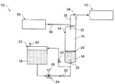
- FIG. 1 illustrates a pressure vessel refueling system that supplies gas at high pressure to a gas dispenser, according to an embodiment of the present invention.
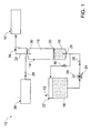
- FIG. 2 is a further illustration of the pressure vessel refueling system of FIG. 1 , wherein the CNG storage vessel is almost empty of gas, according to an embodiment of the present invention.
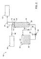
- FIG. 3 is yet a further illustration of the pressure vessel refueling system of FIG. 1 , wherein the CNG storage vessel is almost entirely full of gas.
- Embodiments of the present invention comprise systems and methods for refueling compressed gas pressure vessels using a liquid piston. Elements of the invention are illustrated in concise outline form in the drawings, showing only those specific details that are necessary to the understanding of the embodiments of the present invention, but so as not to clutter the disclosure with excessive detail that will be obvious to those of ordinary skill in the art in light of the present description.
- adjectives such as first and second, left and right, front and back, top and bottom, etc., are used solely to define one element or method step from another element or method step without necessarily requiring a specific relative position or sequence that is described by the adjectives.
- Words such as “comprises” or “includes” are not used to define an exclusive set of elements or method steps. Rather, such words merely define a minimum set of elements or method steps included in a particular embodiment of the present invention.
- the invention includes a pressure vessel refueling system.
- the system includes a pressure vessel having a gas inlet/outlet port and a liquid inlet/outlet port, a first liquid at least partially filling the pressure vessel, and a liquid layer of a second liquid floating on top of the first liquid.
- the first liquid is non-miscible with the second liquid, such that the liquid layer forms a “liquid piston” that is displaced up and down in the vessel as gas is added to and then expelled from the vessel.
- a liquid storage tank is in fluid communication with the liquid inlet/outlet of the pressure vessel, and a pump is in fluid communication with the liquid storage tank. The first liquid thus can be pumped from the liquid storage tank into the pressure vessel to maintain the pressure vessel at a constant pressure as the gas is expelled from the vessel.
- Advantages of the present invention include enabling fast fill refueling methods of CNG fuel tanks using reduced size primary compression and storage.
- the storage is maintained at a constant pressure as gas is discharged, providing opportunity for consistent high pressure filling of CNG fuel tanks.
- Other advantages include reducing a heat rise of the primary storage vessel during its refilling, by avoiding the heat of recompression in the vessel with the application of a back pressure.
- due to the ability to maintain a constant high pressure in the primary storage vessel during refueling a greater number of vehicle fuel tanks can be refueled simultaneously and faster, with lower peak power requirements, as the CNG is already compressed/produced and is simply transferred from storage to the vehicle fuel tank—thus minimising the size of gas and electric utility connections and the associated demand charges.
- CNG cylinders that supply or store gaseous fuel are synonymously referred to as tanks, vessels, pressure vessels, CNG cylinders and cylinders.
- FIG. 1 illustrates a pressure vessel refueling system 10 that supplies gas at high pressure to a gas dispenser 12 .
- the system 10 includes a CNG primary storage vessel 14 that is partially filled with natural gas 16 and partially filled with an aqueous liquid 18 .
- a thin layer of a second liquid in the form of an oil 20 floats on top of the aqueous liquid 18 . Because the oil 20 is both immiscible with the aqueous liquid 18 and is less dense than the aqueous liquid 18 , the layer of oil 20 functions as a “liquid piston” that moves up and down inside the vessel 14 as a volume of the aqueous liquid 18 in the vessel 14 changes.
- the floating layer of oil 20 creates a barrier that prevents the aqueous liquid 18 from contacting and evaporating into the natural gas 16 .
- the oil 20 may become saturated with the natural gas 16 .
- the oil 20 does not leave the storage vessel 14 , and because only a thin layer of oil 20 is required (which becomes saturated with natural gas on initial fill), insignificant natural gas 16 is not available, or is lost from storage.
- the system 10 further includes a liquid storage tank 22 and a pump 24 .
- the pump 24 pumps the aqueous liquid 18 through a check valve 26 and through a lower float valve 28 in a lower inlet/outlet port and into the vessel 14 .
- the natural gas 16 flows through an upper float valve 30 in an upper inlet/outlet port, through a gas line 32 and to the dispenser 12 .
- the layer of oil 20 rises in the vessel 14 and maintains a barrier between the gas 16 and the aqueous liquid 18 .
- the lower float valve 28 functions to prevent the gas 16 from exiting through the bottom of the vessel 14 in the event that all of the aqueous liquid 18 is drained from the vessel 14 .
- the upper float valve 30 functions to prevent the aqueous liquid 18 from exiting through the top of the vessel 14 in the event that all of the gas 16 is pushed out of the vessel 14 by the layer of oil 20 rising to the top of the vessel 14 .
- the lower float valve 28 and the upper float valve 30 can function as described in international patent application no. PCT/AU2012/000265, titled Compressed Natural Gas Tank Float Valve System and Method published on 20 Sep. 2012 under International Publication No. WO2012/122599, the contents of which are hereby incorporated in their entirety.
- a coalescer filter 34 functions as a filter to remove traces of the oil 20 from the gas 16 before such traces reach the dispenser 12 . It is normal in the CNG industry to use such filtration methods to remove trace compressor oil. However, unlike in a compressor, the oil-gas interface is essentially static and does not entrain oil in the gas. Thus the layer of oil 20 enables a significantly more efficient gas transfer system, even though traces of the oil 20 may require filtering by the coalescer 34 .
- a gas compressor 36 can be activated to allow the gas 16 to be compressed and supplied via a check valve 38 from a natural gas supply line (not shown) either into the storage vessel 14 or directly to the dispenser 12 .
- a pressure controller 39 enables the pump 24 to be activated automatically when a pressure drop is detected in the storage vessel 14 .
- the pump 24 enables a high flow rate of gas to be delivered to the dispenser 12 ; that in turn enables, for example, multiple CNG fuel tanks/vehicles to be refueled simultaneously from the dispenser 12 or a plurality of dispensers.
- the steady state power needed by the system 10 to maintain a constant maximum output of gas 16 from the dispenser 12 can be reduced by up to an order of magnitude when compared to using online CNG compression to meet the required delivery rate, from conventional industrial natural gas supply pressures. That means, for example, when refueling several CNG vehicles simultaneously from the dispenser 12 , The compressor 36 can be much smaller than would be required in a comparable refueling system that did not maintain or use a CNG storage vessel at a constant pressure using liquid displacement of the stored gas. According to the present invention the full amount of stored gas is available and deliverable at several times the rate that would otherwise be possible using the equivalent power applied only to a gas compressor.
- the layer of oil 20 applies pressure to the aqueous liquid 18 and opens a back pressure valve 40 .
- the aqueous liquid 18 then flows through the back pressure valve 40 and back into the liquid storage tank 22 .
- air in the tank 22 is vented to atmosphere through a vapour vent 42 .
- FIG. 2 is a further illustration of the pressure vessel refueling system 10 , wherein the CNG storage vessel 14 is almost empty of gas 16 . A considerable volume of aqueous solution 18 has therefore been pumped by the pump 24 from the liquid storage tank 22 into the vessel 14 , enabling the small volume of gas 16 in the vessel 14 to remain at or near a full operating pressure, such as 5000 psig.
- the pump 24 is deactivated and the storage vessel 14 is considered to be empty of gas 16 and in need of re-filling.
- a volumetric analysis of the flow through the pump 24 can be used to determine that the vessel 14 is nearly empty of gas 16 and full of the aqueous solution 18 .
- the upper float valve 30 can be used as a safety mechanism to ensure that the layer of oil 20 is not pumped out of the storage vessel 14 .
- FIG. 3 is yet a further illustration of the pressure vessel refueling system 10 , wherein the CNG storage vessel 14 is almost entirely full of gas 16 .
- the storage vessel 14 is considered to be full of gas 16 .
- a volumetric analysis of the volume of aqueous solution 18 in the storage tank 22 can be used to determine that the vessel 14 is full of gas 16 and nearly empty of the aqueous solution 18 .
- the lower float valve 28 can be used as a safety mechanism to ensure that the layer of oil 20 is not pumped out of the storage vessel 14 and into the storage tank 22 .
- the lower float valve includes a plug (not shown) that sinks in the oil 20 but floats in the aqueous solution 18 —thus retaining the oil 20 in the vessel 14 .
- the aqueous solution 18 is non-gas miscible and the oil 20 is immiscible in water.
- the aqueous solution 18 thus can move in and out of the pressurized storage vessel 14 without carrying dissolved gas 16 .
- the aqueous solution 18 can be, for example, a salt solution to act as an anti-freeze and hydrate formation suppressant to prevent solids forming in the system 10 .
- various types of non-water miscible fluids can be used as the oil 20 , such as various mineral oils or organic oils.
- the single storage vessel 14 can be replaced by a plurality of vessels operating in parallel both when being refilled with the gas 16 and when discharging the gas 16 .
- each pressure vessel in the plurality of vessels will include a layer of the oil 20 floating on top of the aqueous solution 18 , and will operate as described herein concerning the vessel 14 .
- Use of such a plurality of vessels enables significantly greater gas storage capacity in a single system 10 .
- advantages of the present invention include enabling fast fill refueling methods of CNG fuel tanks by utilising the full capacity of the installed storage and delivering that storage using substantially less power than that required by equivalent gas compression plant to meet peak demands.
- the storage is maintained at a constant pressure as gas is discharged enabling complete filling of tanks/vehicles.
- the system thus minimises the size of gas and electric utility connections and the associated demand charges. This leverages the delivery capacity of CNG fuelling stations that are limited by utility connections and can make sizable CNG stations feasible where only limited utility connections exist.
- the present invention can eliminate the issue of in cylinder recompression heating inside CNG storage cylinders when filling the storage, enabling consistent filling to a pressure vessel's standard ambient temperature pressure rating at design pressures. This provides increased CNG storage or the opportunity to reduce storage vessel sizes.
Applications Claiming Priority (3)
| Application Number | Priority Date | Filing Date | Title |
|---|---|---|---|
| AU2012905411A AU2012905411A0 (en) | 2012-12-10 | System and method for refuelling compressed gas pressure vessels using a liquid piston | |
| AU2012905411 | 2012-12-10 | ||
| PCT/AU2013/001433 WO2014089608A1 (en) | 2012-12-10 | 2013-12-10 | System and method for refuelling compressed gas pressure vessels using a liquid piston |
Publications (2)
| Publication Number | Publication Date |
|---|---|
| US20150354754A1 US20150354754A1 (en) | 2015-12-10 |
| US9791105B2 true US9791105B2 (en) | 2017-10-17 |
Family
ID=50933571
Family Applications (1)
| Application Number | Title | Priority Date | Filing Date |
|---|---|---|---|
| US14/649,881 Active 2034-02-05 US9791105B2 (en) | 2012-12-10 | 2013-12-10 | System and method for refuelling compressed gas pressure vessels using a liquid piston |
Country Status (7)
| Country | Link |
|---|---|
| US (1) | US9791105B2 (zh) |
| EP (1) | EP2929230B1 (zh) |
| CN (1) | CN104956141B (zh) |
| AU (1) | AU2013360009B2 (zh) |
| CA (1) | CA2893774C (zh) |
| NZ (1) | NZ708944A (zh) |
| WO (1) | WO2014089608A1 (zh) |
Families Citing this family (9)
| Publication number | Priority date | Publication date | Assignee | Title |
|---|---|---|---|---|
| US20170097121A1 (en) * | 2015-10-06 | 2017-04-06 | Johnson Research & Development Co., Inc. | Compressed gas storage system |
| EP3522995A1 (en) * | 2016-10-05 | 2019-08-14 | Tyco Building Services Products Limited | Methods and system for filling a suppressant container |
| EP3899349A4 (en) * | 2018-12-17 | 2022-08-17 | Gas Technologies L.L.C. | GAS COMPRESSION DEVICE AND SYSTEM AND METHOD OF COMPRESSING A GAS |
| CN110131580A (zh) * | 2019-05-05 | 2019-08-16 | 安瑞科(廊坊)能源装备集成有限公司 | 液压式天然气汽车加气子站的回油系统 |
| CN113108234B (zh) * | 2021-04-16 | 2023-06-06 | 菏泽城建工程发展集团有限公司 | 一种服务于乡村振兴的燃气储存装置 |
| WO2023114228A1 (en) * | 2021-12-13 | 2023-06-22 | Hydrogen Active Storage Solutions, Inc. | Hydrogen compression, storage, and dispensing |
| CN115031152A (zh) * | 2022-06-30 | 2022-09-09 | 势加透博(北京)科技有限公司 | 天然气调峰系统 |
| GB202210468D0 (en) * | 2022-07-15 | 2022-08-31 | Fraenkel Wright Ltd | Bulk gas storage |
| WO2024013499A1 (en) * | 2022-07-15 | 2024-01-18 | Fraenkel Wright Limited | Gas storage using liquid for gas displacement |
Citations (9)
| Publication number | Priority date | Publication date | Assignee | Title |
|---|---|---|---|---|
| US1938956A (en) | 1931-06-29 | 1933-12-12 | Harry A Fee | Gas pressure maintenance |
| GB1170294A (en) | 1967-01-27 | 1969-11-12 | Halliburton Co | Underground Cryogenic Storage of Liquefied Gas |
| US4209271A (en) | 1978-08-10 | 1980-06-24 | Chicago Bridge & Iron Company | Storage tank with liquid insulator for storing cryogenic fluids using water displacement |
| US4805674A (en) * | 1987-09-16 | 1989-02-21 | C-I-L Inc. | Natural gas storage and retrieval system |
| US5454408A (en) | 1993-08-11 | 1995-10-03 | Thermo Power Corporation | Variable-volume storage and dispensing apparatus for compressed natural gas |
| US6439278B1 (en) | 2001-03-16 | 2002-08-27 | Neogas Inc. | Compressed natural gas dispensing system |
| US20080041068A1 (en) | 2006-08-19 | 2008-02-21 | Horton Edward E | Liquefied natural gas re-gasification and storage unit |
| US20080127654A1 (en) | 2006-07-20 | 2008-06-05 | Darling Charles M | Container for Transport and Storage for Compressed Natural Gas |
| US20100139777A1 (en) | 2006-12-21 | 2010-06-10 | Mosaic Technologies Pty Ltd | compressed gas transfer system |
-
2013
- 2013-12-10 NZ NZ708944A patent/NZ708944A/en unknown
- 2013-12-10 AU AU2013360009A patent/AU2013360009B2/en active Active
- 2013-12-10 US US14/649,881 patent/US9791105B2/en active Active
- 2013-12-10 EP EP13862275.8A patent/EP2929230B1/en active Active
- 2013-12-10 CA CA2893774A patent/CA2893774C/en active Active
- 2013-12-10 WO PCT/AU2013/001433 patent/WO2014089608A1/en active Application Filing
- 2013-12-10 CN CN201380071470.0A patent/CN104956141B/zh active Active
Patent Citations (9)
| Publication number | Priority date | Publication date | Assignee | Title |
|---|---|---|---|---|
| US1938956A (en) | 1931-06-29 | 1933-12-12 | Harry A Fee | Gas pressure maintenance |
| GB1170294A (en) | 1967-01-27 | 1969-11-12 | Halliburton Co | Underground Cryogenic Storage of Liquefied Gas |
| US4209271A (en) | 1978-08-10 | 1980-06-24 | Chicago Bridge & Iron Company | Storage tank with liquid insulator for storing cryogenic fluids using water displacement |
| US4805674A (en) * | 1987-09-16 | 1989-02-21 | C-I-L Inc. | Natural gas storage and retrieval system |
| US5454408A (en) | 1993-08-11 | 1995-10-03 | Thermo Power Corporation | Variable-volume storage and dispensing apparatus for compressed natural gas |
| US6439278B1 (en) | 2001-03-16 | 2002-08-27 | Neogas Inc. | Compressed natural gas dispensing system |
| US20080127654A1 (en) | 2006-07-20 | 2008-06-05 | Darling Charles M | Container for Transport and Storage for Compressed Natural Gas |
| US20080041068A1 (en) | 2006-08-19 | 2008-02-21 | Horton Edward E | Liquefied natural gas re-gasification and storage unit |
| US20100139777A1 (en) | 2006-12-21 | 2010-06-10 | Mosaic Technologies Pty Ltd | compressed gas transfer system |
Also Published As
| Publication number | Publication date |
|---|---|
| EP2929230A4 (en) | 2017-05-17 |
| WO2014089608A1 (en) | 2014-06-19 |
| EP2929230B1 (en) | 2022-09-28 |
| CN104956141A (zh) | 2015-09-30 |
| CA2893774A1 (en) | 2014-06-19 |
| NZ708944A (en) | 2018-08-31 |
| CA2893774C (en) | 2021-06-08 |
| EP2929230A1 (en) | 2015-10-14 |
| CN104956141B (zh) | 2017-06-20 |
| AU2013360009B2 (en) | 2018-06-07 |
| US20150354754A1 (en) | 2015-12-10 |
| AU2013360009A1 (en) | 2015-07-02 |
Similar Documents
| Publication | Publication Date | Title |
|---|---|---|
| US9791105B2 (en) | System and method for refuelling compressed gas pressure vessels using a liquid piston | |
| US10132447B2 (en) | System and method for refueling a compressed gas pressure vessel using a thermally coupled nozzle | |
| CA2672643C (en) | A compressed gas transfer system | |
| WO2013056295A1 (en) | System and method for refuelling of compressed gas pressure vessels | |
| US9482388B2 (en) | Skid-mounted compressed gas dispensing systems, kits, and methods for using same | |
| US20170241592A1 (en) | System and method for refuelling a compressed gas pressure vessel using a cooling circuit and in-vessel temperature stratification | |
| US9080726B2 (en) | Tank system for a motor vehicle, and operating method for the same | |
| US8991446B2 (en) | Pump assisted refilling system for LPG fuel tanks | |
| WO2012122599A1 (en) | Compressed natural gas tank float valve system and method | |
| US20190376648A1 (en) | System and method for balanced refuelling of a plurality of compressed gas pressure vessels |
Legal Events
| Date | Code | Title | Description |
|---|---|---|---|
| AS | Assignment |
Owner name: MOSAIC TECHNOLOGY DEVELOPMENT PTY, LTD, AUSTRALIA Free format text: ASSIGNMENT OF ASSIGNORS INTEREST;ASSIGNORS:WHITEMAN, PAUL ANTHONY;FEKETE, DEREK SHANE;REEL/FRAME:036164/0492 Effective date: 20150703 |
|
| STCF | Information on status: patent grant |
Free format text: PATENTED CASE |
|
| FEPP | Fee payment procedure |
Free format text: ENTITY STATUS SET TO UNDISCOUNTED (ORIGINAL EVENT CODE: BIG.); ENTITY STATUS OF PATENT OWNER: LARGE ENTITY |
|
| FEPP | Fee payment procedure |
Free format text: PETITION RELATED TO MAINTENANCE FEES GRANTED (ORIGINAL EVENT CODE: PTGR); ENTITY STATUS OF PATENT OWNER: LARGE ENTITY |
|
| MAFP | Maintenance fee payment |
Free format text: PAYMENT OF MAINTENANCE FEE, 4TH YEAR, LARGE ENTITY (ORIGINAL EVENT CODE: M1551); ENTITY STATUS OF PATENT OWNER: LARGE ENTITY Year of fee payment: 4 |