US9786974B2 - Tunable band-pass filter - Google Patents
Tunable band-pass filter Download PDFInfo
- Publication number
- US9786974B2 US9786974B2 US14/436,009 US201314436009A US9786974B2 US 9786974 B2 US9786974 B2 US 9786974B2 US 201314436009 A US201314436009 A US 201314436009A US 9786974 B2 US9786974 B2 US 9786974B2
- Authority
- US
- United States
- Prior art keywords
- pass filter
- tunable band
- conductor
- movable
- filter according
- Prior art date
- Legal status (The legal status is an assumption and is not a legal conclusion. Google has not performed a legal analysis and makes no representation as to the accuracy of the status listed.)
- Active, expires
Links
Images


Classifications
-
- H—ELECTRICITY
- H01—ELECTRIC ELEMENTS
- H01P—WAVEGUIDES; RESONATORS, LINES, OR OTHER DEVICES OF THE WAVEGUIDE TYPE
- H01P1/00—Auxiliary devices
- H01P1/20—Frequency-selective devices, e.g. filters
- H01P1/201—Filters for transverse electromagnetic waves
- H01P1/205—Comb or interdigital filters; Cascaded coaxial cavities
- H01P1/2053—Comb or interdigital filters; Cascaded coaxial cavities the coaxial cavity resonators being disposed parall to each other
-
- H—ELECTRICITY
- H01—ELECTRIC ELEMENTS
- H01P—WAVEGUIDES; RESONATORS, LINES, OR OTHER DEVICES OF THE WAVEGUIDE TYPE
- H01P1/00—Auxiliary devices
- H01P1/20—Frequency-selective devices, e.g. filters
- H01P1/201—Filters for transverse electromagnetic waves
- H01P1/205—Comb or interdigital filters; Cascaded coaxial cavities
- H01P1/2056—Comb filters or interdigital filters with metallised resonator holes in a dielectric block
-
- H—ELECTRICITY
- H01—ELECTRIC ELEMENTS
- H01P—WAVEGUIDES; RESONATORS, LINES, OR OTHER DEVICES OF THE WAVEGUIDE TYPE
- H01P1/00—Auxiliary devices
- H01P1/20—Frequency-selective devices, e.g. filters
- H01P1/207—Hollow waveguide filters
-
- H—ELECTRICITY
- H01—ELECTRIC ELEMENTS
- H01P—WAVEGUIDES; RESONATORS, LINES, OR OTHER DEVICES OF THE WAVEGUIDE TYPE
- H01P1/00—Auxiliary devices
- H01P1/20—Frequency-selective devices, e.g. filters
- H01P1/207—Hollow waveguide filters
- H01P1/208—Cascaded cavities; Cascaded resonators inside a hollow waveguide structure
- H01P1/2084—Cascaded cavities; Cascaded resonators inside a hollow waveguide structure with dielectric resonators
-
- H—ELECTRICITY
- H01—ELECTRIC ELEMENTS
- H01P—WAVEGUIDES; RESONATORS, LINES, OR OTHER DEVICES OF THE WAVEGUIDE TYPE
- H01P7/00—Resonators of the waveguide type
- H01P7/04—Coaxial resonators
-
- H—ELECTRICITY
- H01—ELECTRIC ELEMENTS
- H01P—WAVEGUIDES; RESONATORS, LINES, OR OTHER DEVICES OF THE WAVEGUIDE TYPE
- H01P7/00—Resonators of the waveguide type
- H01P7/06—Cavity resonators
Landscapes
- Physics & Mathematics (AREA)
- Electromagnetism (AREA)
- Control Of Motors That Do Not Use Commutators (AREA)
Abstract
The present invention comprises: a conductive chassis having a cavity resonator; a conductive cover to cover the cavity resonator; a resonant element arranged in the cavity resonator, one end of the resonant element being connected with the chassis and the other end being open end; and a movable conductor arranged in a space between the open end of the resonant element and the conductive cover. As a result, a tunable band-pass filter which is inexpensive and of a simple structure and which can change a resonance frequency of a cavity resonator and the coupling amount between cavity resonators easily is realized.
Description
The present application is a national stage application of International Application No. PCT/JP2013/006181 entitled “Turnable Band-Pass Filter,” filed on Oct. 18, 2013, which claims the benefit of priority from Japanese Patent Application No. JP2012-233659, filed on Oct. 23, 2012, the disclosures of which are incorporated herein in their entirety by reference thereto.
The present invention relates to a band-pass filter used in a microwave and a millimeter wave, and, more particularly, to a tunable band-pass filter which can vary a resonance frequency.
In a radio communication system that performs transmission and reception using a microwave or a millimeter wave band, a band-pass filter is used to make only a signal of a desired frequency band pass, and to remove a signal of an unnecessary bandwidth. When a band-pass filter is used at a plurality of center frequencies, there is a technological case described in patent literature 1. In patent literature 1, there is disclosed a technology in which, in the metal housing of a semi-coaxial band-pass filter, a dielectric having a movable structure is provided and a resonance frequency of a resonator is made to be changed by moving this.
[PTL 1] International Publication No. WO 2006/075439
However, in the technology described in patent literature 1, in order to change a resonance frequency within a suitable range, a special dielectric material, a dielectric material having a high permittivity such as a compound of a rare-earth barium titanate system, for example, is required, and, as a result, increase of cost is caused.
Further, when forming a band-pass filter, it needs to be of a system in which a dielectric member is used in each stage of a cavity semi-coaxial resonator of a plurality of stages and these plurality of dielectric members are moved simultaneously. At that time, there is a problem that the structure becomes complicated because a holding member which joins a dielectric member and a movable member connected with the dielectric member is needed due to a difference of material between them.
The present invention has been made in view of the above-mentioned subject, and its object is to provide a tunable band-pass filter which is of low cost and of a simple structure, and which can change a resonance frequency of a resonator and a coupling amount (or, a coupling coefficient) between resonators easily.
A tunable band-pass filter of the present invention comprises: a conductive chassis having a cavity resonator; a conductive cover to cover said cavity resonator; a resonant element arranged in said cavity resonator, one end of said resonant element being connected with said chassis and an other end being open end; and a movable conductor arranged in a space between said open end of said resonant element and said conductive cover.
According to a tunable band-pass filter of the present invention, it becomes possible to provide a tunable band-pass filter which is of low cost and of a simple structure, and which can change a resonance frequency of a resonator and a coupling amount between resonators easily.
Hereinafter, an exemplary embodiment of the present invention will be described in detail with reference to a drawing. However, although limitation that is technically preferred to carry out the present invention is being imposed to exemplary embodiments described below, the scope of the invention is not limited to the followings.
A tunable band-pass filter of the first exemplary embodiment of the present invention will be described in detail using FIG. 1A and FIG. 1B . FIG. 1A is a perspective view showing a structure of the first exemplary embodiment of the present invention. In FIG. 1A , there is indicated a band-pass filter including pieces of cavity resonator 20 of three stages. FIG. 1B indicates a sectional view of one piece of cavity resonator 20 among the pieces of cavity resonator 20 of three stages shown in FIG. 1A .
The cavity resonator 20 is formed by a combination of a conductive chassis 1 and a conductive cover 2. Although the cavity resonator 20 is of a cylindrical shape in FIG. 1A , it is not limited to a cylindrical shape, and it may be of another shape such as a prismatic shape. A window 21 of a structure made by cutting out a part of said cylindrical shape connects between each cavity resonator. The shape of the window 21 is not limited to the shape shown in FIG. 1A , and it may be of a shape besides this shape such as a cylinder, and the width of the cutout may be made to be about the same as the diameter of the cylinder of the cavity resonator 20.
A resonant element 3 is installed in the cavity resonator 20, and its one end is connected to the conductive chassis 1 and the other end which is in the side facing the conductive cover 2 is open. As a shape of the resonant element 3, a tabular shape, a prism or a column is possible, but not limited to these. For example, a shape having a bend of an L letterform is also possible. As material of the resonant element 3, a conductor or a dielectric is possible.
There are provided, in the cavity resonators of the both ends among the three pieces of cavity resonator 20 which form a band-pass filter, an input terminal 7 for inputting a radio wave from outside and exciting said resonant element 3 and an output terminal 8 for outputting a radio wave which has passed said plurality of pieces of resonant element 3 outside the chassis. In FIG. 1A , although a three-stage band-pass filter having three pieces of cavity resonator 20 is being disclosed, the number of pieces of cavity resonator 20 is not limited. Furthermore, the input terminal 7 and the output terminal 8 are ones which have been defined for convenience of description of operation, and thus it is possible to input a radio wave from the output terminal 8, and take out a radio wave from the input terminal 7.
There is arranged a conductor 5 made of a conductive member between each piece of resonant element 3 and the conductive cover 2. An inexpensive metal such as copper and aluminum is possible as the material of the conductor 5. The conductor 5 is arranged for each piece of cavity resonator 20, and neighboring pieces of conductor 5 are connected by a non-conductive member 6. As the non-conductive member 6, an inexpensive member such as ceramic and resin is possible. In order to connect the non-conductive member 6 and the conductor 5, a connection member (no code attached in FIG. 1A ) may be provided between the non-conductive member 6 and the conductor 5. Although the material of this connection member is optional, it is possible to use an inexpensive member of metal, ceramic or resin. The conductor 5 may be one having a size and a shape different for each piece of cavity resonator 20.
Among the both ends of the train of pieces of conductor 5 connected by pieces of non-conductive member 6, one end penetrates through the conductive chassis 1 by a support 9, and, in addition, is made to be able to rotate about an axis to make the conductor 5 be movable from outside of the conductive chassis 1 of the band-pass filter. Here, said one end does not need to penetrate. The other end penetrates through the conductive chassis 1, is taken out outside, and is also made to be able to be axis-rotated. As motive power of this axial rotation, a stepping motor 10 or the like whose rotation is controlled by a computer can be used although manual may be acceptable.
According to the exemplary embodiment disclosed above, a band-pass filter is inexpensive because the conductor 5 made of metal such as copper and aluminum that is of low cost is used between each resonant element 3 and the conductive cover 2. Furthermore, its structure is simple because the conductor 5 is not a dielectric member and thus is easy to be connected with a moving member, resulting in a holding member that would be necessary to join a dielectric member or the like being unnecessary. That is, as an effect of this exemplary embodiment, it is possible to provide a tunable band-pass filter which is of an inexpensive and of an easy structure, and which can change a resonance frequency of the cavity resonator 20 easily.
Further, using FIG. 2 , a tunable band-pass filter which can, in addition to the above effect, change a coupling amount between pieces of cavity resonator 20 is disclosed. A coupling amount or a coupling coefficient is related to a band of a band-pass filter, and when it is large, a band is wide, and, when it is small, a band is narrow. FIG. 2 indicates a structure in which a conductor 5 b that is similar to the conductor 5 is also provided in a position corresponding to the window 21 between pieces of cavity resonator 20. Each piece of conductor 5 and a piece of conductor 5 b are connected via a non-conductive member 6 b.
The conductor 5 b has a function to adjust a coupling amount between pieces of cavity resonator 20. That is, a coupling amount between pieces of cavity resonator 20 changes according to a resonance frequency of the cavity resonator 20 being changed by the conductor 5 provided above the resonant element 3. These pieces of conductor 5 b do not need to be of an identical size and a shape among respective pieces of cavity resonator 20, and a size and a shape that are suitable for each of them can be selected.
Next, an effect in this exemplary embodiment will be described using FIG. 6 . FIG. 6 indicates a state of a change in a resonance frequency of a band-pass filter of 8000 MHz band when, in the structure of FIG. 1A , rotating the conductor 5 in the downward direction of the arrow in the figure. At that time, the diameter of the cavity resonator 20 is 11 mm and the length 11 mm, and the width of the conductor 5 is 6 mm, the length 8 mm and the thickness 0.5 mm. The conductor 5 is in a position that is 8 mm from the bottom base of the cavity resonator 20, and the supporting point 12 of rotation is in a position that is offset from the center axis of the cavity resonator 20 by 3 mm. An inclined angle of 0 degree indicates a state that the conductor 5 is parallel to the conductive cover 2. By changing the angle of rotation from 0 degree to 15 degrees, a resonance frequency has declined by about 300 MHz. There are almost no return-loss deteriorations during that span.
As above, according to this exemplary embodiment, a tunable band-pass filter which is inexpensive and of a simple structure and which can change a resonance frequency of a cavity resonator and a coupling amount between cavity resonators easily can be provided.
The second exemplary embodiment of the present invention will be described using FIG. 3A and FIG. 3B . FIG. 3A is a structure in which, in place of the conductor 5 of the first exemplary embodiment, a conductor 5 d shown in FIG. 3B is formed on the face of a non-conductive member 5 c in the side of the resonant element 3. FIG. 3B shows a conductor structure used in FIG. 3A . For example, a structure in which the conductor 5 d made of a metallic film such as copper is formed on the non-conductive member 5 c such as a printed wiring board can be used as a conductor. The conductor structure in which the conductor 5 d is formed onto the non-conductive member 5 c is connected by a connection member (no code attached in FIG. 3B ) forming a rotating shaft.
The other components in this exemplary embodiment are the same as those of the first exemplary embodiment. That is, according to this exemplary embodiment, a tunable band-pass filter which is inexpensive and of a simple structure, and which can change a resonance frequency of a cavity resonator and a coupling amount between cavity resonators easily can be provided.
The third exemplary embodiment of the present invention will be described using FIG. 4 . FIG. 4 is a structure in which, in place of the conductor 5 of the first exemplary embodiment, a conductor 5 e having a hole 13 which can let the frequency adjustment screw 4 through is provided. As a result, it also becomes possible to carry out frequency adjustment using the frequency adjustment screw 4 without influence of rotation of the conductor 5 e, and thus a variable range of a resonance frequency as a band-pass filter can be expanded.
The other components of this exemplary embodiment are the same as those of the first exemplary embodiment. That is, according to this exemplary embodiment, a tunable band-pass filter which is inexpensive and of a simple structure and which can change a resonance frequency of a cavity resonator and a coupling amount between cavity resonators easily can be provided.
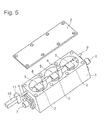
The fourth exemplary embodiment of the present invention will be described using FIG. 5 . FIG. 5 is a structure in which, in place of the rotating mechanism of the conductor 5 of the first exemplary embodiment, a rotational movement of a motor 10 is converted into an up and down movement by a gear 11 to make the conductor 5 move up and down. By moving it up and down, a resonance frequency can be changed by a distance between the conductor 5 and the resonant element 3 changing.
The other components of this exemplary embodiment are the same as those of the first exemplary embodiment. That is, according to this exemplary embodiment, a tunable band-pass filter which is inexpensive and of a simple structure and which can change a resonance frequency of a cavity resonator and a coupling amount between cavity resonators easily can be provided.
Various transformations are possible to the present invention within the scope of the invention described in the claims without limited to the above-mentioned exemplary embodiments, and it goes without saying that those are also included within the scope of the present invention. Part or all of the above-mentioned exemplary embodiments can also be described like the following supplementary notes, but not limited to them.
Supplementary Note
(Supplementary Note 1)
A tunable band-pass filter, comprising: a conductive chassis having a cavity resonator; a conductive cover to cover said cavity resonator; a resonant element arranged in said cavity resonator, one end of said resonant element being connected with said chassis and an other end being open end; and a movable conductor arranged in a space between said open end of said resonant element and said conductive cover.
(Supplementary Note 2)
The tunable band-pass filter according to supplementary note 1, wherein there are a plurality of pieces of said cavity resonator, and said movable conductor is also deployed in a space between said cavity resonator and said cavity resonator.
(Supplementary Note 3)
The tunable band-pass filter according to any one of supplementary notes 1 to 2, wherein said movable conductor is connected by a non-conductivity material.
(Supplementary Note 4)
The tunable band-pass filter according to any one of supplementary notes 1 to 3, wherein movement of said movable conductor is a rotating movement.
(Supplementary Note 5)
The tunable band-pass filter according to any one of supplementary notes 1 to 3, wherein movement of said movable conductor is a linear movement.
(Supplementary Note 6)
The tunable band-pass filter according to any one of supplementary notes 1 to 5, having a frequency adjustment screw screwed in from said conductive cover in a manner facing said resonant element.
(Supplementary Note 7)
The tunable band-pass filter according to supplementary note 6, wherein said movable conductor has a hole corresponding to said frequency adjustment screw.
(Supplementary Note 8)
The tunable band-pass filter according to any one of supplementary notes 1 to 7, wherein said movable conductor is a non-conductivity material having a metallic film formed on said non-conductivity material.
(Supplementary Note 9)
The tunable band-pass filter according to any one of supplementary notes 1 to 8, wherein said resonant element is one of a conductor and a dielectric, having a shape selected from a tabular shape, a prismatic column and a circular cylinder.
(Supplementary Note 10)
The tunable band-pass filter according to any one of supplementary notes 1 to 9, wherein a source of power of said movable conductor is a motor.
(Supplementary Note 11)
The tunable band-pass filter according to supplementary note 10, wherein said motor is controlled by a computer.
This application claims priority based on Japanese application Japanese Patent Application No. 2012-233659 filed on Oct. 23, 2012, the disclosure of which is incorporated herein in its entirety.
The present invention relates to a band-pass filter used in a microwave and a millimeter wave, and, more particularly, to a tunable band-pass filter which can vary a resonance frequency.
-
- 1 Conductive chassis
- 2 Conductive cover
- 3 Resonant element
- 4 Frequency adjustment screw
- 5, 5 b, 5 d and 5 e Conductor
- 5 c Non-conductive member
- 6 and 6 b Non-conductive member
- 7 Input terminal
- 8 Output terminal
- 9 Support
- 10 Motor
- 11 Gear
- 12 Supporting point
- 13 Hole
- 20 Cavity resonator
- 21 Window
Claims (16)
1. A tunable band-pass filter, comprising:
a conductive chassis having a plurality of pieces of a cavity resonator;
a conductive cover to cover said plurality of pieces of the cavity resonator;
a plurality of resonant elements arranged in each said plurality of pieces of the cavity resonator, one end of said resonant elements being connected with said chassis and another end being an open end; and
a plurality of movable conductors arranged in a space between said open end of said resonant elements and said conductive cover,
wherein the plurality of movable conductors are in a space between pieces of the plurality of pieces of the cavity resonator,
wherein the plurality of movable conductors are arranged above the plurality of resonant elements,
wherein the plurality of movable conductor are between resonant elements,
wherein the plurality of movable conductors move synchronously.
2. The tunable band-pass filter according to claim 1 , wherein a source of power of said movable conductors is a motor.
3. The tunable band-pass filter according to claim 1 , wherein each of said movable conductors is connected by a non-conductivity material.
4. The tunable band-pass filter according to claim 1 , wherein movement of said movable conductors is a rotating movement.
5. The tunable band-pass filter according to claim 1 , wherein movement of said movable conductors is a linear movement.
6. The tunable band-pass filter according to claim 1 , having a frequency adjustment screw inserted in from said conductive cover in a manner facing at least one of said resonant elements.
7. The tunable band-pass filter according to claim 6 , wherein at least one of said movable conductors has a hole corresponding to said frequency adjustment screw, wherein the frequency adjustment screw passes through the hole in the at least one of said movable conductors, wherein the at least one of said movable conductors rotates around an axis approximately perpendicular to an axis of the frequency adjustment screw.
8. The tunable band-pass filter according to claim 1 , wherein each of said movable conductors is a non-conductivity material having a metallic film formed on said non-conductivity material.
9. The tunable band-pass filter according to claim 1 , wherein each of said plurality of resonant elements is one of a conductor and a dielectric, having a shape selected from a tabular shape, a prismatic column and a circular cylinder.
10. A tunable band-pass filter, comprising:
a conductive chassis having a plurality of pieces of a cavity resonator;
a conductive cover to cover said plurality of pieces of the cavity resonator;
a resonant element arranged in said plurality of pieces of the cavity resonator, one end of each said resonant element being connected with said chassis and another end being an open end;
a movable conductor arranged in a space between said open end of said resonant element and said conductive cover; and
a frequency adjustment screw inserted in from said conductive cover in a manner facing said resonant element,
wherein said movable conductor has a hole corresponding to said frequency adjustment screw,
wherein the frequency adjustment screw passes through the hole in the movable conductor,
wherein the movable conductor rotates around an axis approximately perpendicular to an axis of the frequency adjustment screw.
11. The tunable band-pass filter according to claim 10 , wherein said movable conductor is connected by a non-conductivity material.
12. The tunable band-pass filter according to claim 10 , wherein movement of said movable conductor is a rotating movement.
13. The tunable band-pass filter according to claim 10 , wherein movement of said movable conductor is a linear movement.
14. The tunable band-pass filter according to claim 10 , wherein said movable conductor is a non-conductivity material having a metallic film formed on said non-conductivity material.
15. The tunable band-pass filter according to claim 10 , wherein said resonant element is one of a conductor and a dielectric, having a shape selected from a tabular shape, a prismatic column, and a circular cylinder.
16. The tunable band-pass filter according to claim 10 , wherein a source of power of said movable conductor is a motor.
Applications Claiming Priority (3)
| Application Number | Priority Date | Filing Date | Title |
|---|---|---|---|
| JP2012233659A JP6006079B2 (en) | 2012-10-23 | 2012-10-23 | Tunable bandpass filter |
| JP2012-233659 | 2012-10-23 | ||
| PCT/JP2013/006181 WO2014064911A1 (en) | 2012-10-23 | 2013-10-18 | Tunable band-pass filter |
Publications (2)
| Publication Number | Publication Date |
|---|---|
| US20150280298A1 US20150280298A1 (en) | 2015-10-01 |
| US9786974B2 true US9786974B2 (en) | 2017-10-10 |
Family
ID=50544296
Family Applications (1)
| Application Number | Title | Priority Date | Filing Date |
|---|---|---|---|
| US14/436,009 Active 2034-03-18 US9786974B2 (en) | 2012-10-23 | 2013-10-18 | Tunable band-pass filter |
Country Status (6)
| Country | Link |
|---|---|
| US (1) | US9786974B2 (en) |
| EP (1) | EP2913884B1 (en) |
| JP (1) | JP6006079B2 (en) |
| CN (1) | CN104756312A (en) |
| IN (1) | IN2015DN03044A (en) |
| WO (1) | WO2014064911A1 (en) |
Cited By (1)
| Publication number | Priority date | Publication date | Assignee | Title |
|---|---|---|---|---|
| US11431068B2 (en) * | 2020-05-26 | 2022-08-30 | Nec Corporation | Frequency variable filter and coupling method |
Families Citing this family (11)
| Publication number | Priority date | Publication date | Assignee | Title |
|---|---|---|---|---|
| WO2016075852A1 (en) * | 2014-11-10 | 2016-05-19 | 日本電気株式会社 | Bandpass filter and wireless communication device |
| CN107204503B (en) * | 2016-03-18 | 2020-05-05 | 通玉科技有限公司 | RF filter |
| KR101818109B1 (en) | 2016-03-25 | 2018-01-12 | (주)에드모텍 | The frequency-variable filter improving insertion loss |
| WO2017170120A1 (en) | 2016-03-31 | 2017-10-05 | 日本電気株式会社 | Tunable bandpass filter |
| WO2017199766A1 (en) | 2016-05-20 | 2017-11-23 | 日本電気株式会社 | Band-pass filter and control method therefor |
| WO2019097559A1 (en) * | 2017-11-16 | 2019-05-23 | Rf Microtech S.R.L. | Tunable band-pass filter |
| JP7303063B2 (en) * | 2019-08-20 | 2023-07-04 | 日本電気株式会社 | Resonator and manufacturing method |
| US10790795B1 (en) * | 2019-12-25 | 2020-09-29 | Universal Microwave Technology, Inc. | Zeroing structure applicable to adjustable diplexer |
| JP2024513511A (en) * | 2021-04-19 | 2024-03-25 | ケーエムダブリュ・インコーポレーテッド | switchable filter |
| CN115000656A (en) * | 2022-04-13 | 2022-09-02 | 华南理工大学 | Adjustable filter and adjustable duplexer based on coaxial cavity resonator |
| CN115101908B (en) * | 2022-06-27 | 2024-04-05 | 苏州市协诚微波技术有限公司 | Metal filter and assembling method thereof |
Citations (14)
| Publication number | Priority date | Publication date | Assignee | Title |
|---|---|---|---|---|
| US4459570A (en) * | 1980-08-29 | 1984-07-10 | Thomson-Csf | Ultra-high frequency filter with a dielectric resonator tunable in a large band width |
| JPS59121903U (en) | 1984-01-19 | 1984-08-16 | トムソン−セ−エスエフ | ultra high frequency filter |
| JPH07131217A (en) | 1993-11-08 | 1995-05-19 | Kyocera Corp | Dielectric resonator |
| JPH07263926A (en) | 1994-03-25 | 1995-10-13 | Kyocera Corp | Dielectric resonator |
| JPH09172304A (en) | 1995-12-21 | 1997-06-30 | Fujitsu Ltd | Impedance adjusting unit for coplaner line |
| JP2001257511A (en) | 2000-03-14 | 2001-09-21 | Murata Mfg Co Ltd | Resonator, filter duplexer and communication equipment |
| JP2003318612A (en) | 2002-04-23 | 2003-11-07 | Pearl Kogyo Kk | Matching device |
| CN1585188A (en) | 2003-08-23 | 2005-02-23 | Kmw株式会社 | Variable radio frequency band filter |
| WO2006075439A1 (en) | 2005-01-11 | 2006-07-20 | Murata Manufacturing Co., Ltd. | Tunable filter, duplexer and communication apparatus |
| US20090058563A1 (en) | 2007-08-28 | 2009-03-05 | Ace Technology | Frequency Tunable Filter |
| US20090237185A1 (en) | 2008-03-04 | 2009-09-24 | Nokia Siemens Networks Oy | Variable radio frequency band filter |
| US20110133862A1 (en) | 2008-08-07 | 2011-06-09 | Dong-Wan Chun | Tunable filter capable of controlling tuning characteristics |
| JP2011142460A (en) | 2010-01-06 | 2011-07-21 | Nippon Dengyo Kosaku Co Ltd | Method of automatically adjusting filter characteristic |
| US20120119850A1 (en) | 2010-11-12 | 2012-05-17 | Paeri Petri | Adjustable resonator filter |
-
2012
- 2012-10-23 JP JP2012233659A patent/JP6006079B2/en not_active Expired - Fee Related
-
2013
- 2013-10-18 WO PCT/JP2013/006181 patent/WO2014064911A1/en active Application Filing
- 2013-10-18 IN IN3044DEN2015 patent/IN2015DN03044A/en unknown
- 2013-10-18 CN CN201380055643.XA patent/CN104756312A/en active Pending
- 2013-10-18 EP EP13848804.4A patent/EP2913884B1/en not_active Not-in-force
- 2013-10-18 US US14/436,009 patent/US9786974B2/en active Active
Patent Citations (18)
| Publication number | Priority date | Publication date | Assignee | Title |
|---|---|---|---|---|
| US4459570A (en) * | 1980-08-29 | 1984-07-10 | Thomson-Csf | Ultra-high frequency filter with a dielectric resonator tunable in a large band width |
| JPS59121903U (en) | 1984-01-19 | 1984-08-16 | トムソン−セ−エスエフ | ultra high frequency filter |
| JPH07131217A (en) | 1993-11-08 | 1995-05-19 | Kyocera Corp | Dielectric resonator |
| JPH07263926A (en) | 1994-03-25 | 1995-10-13 | Kyocera Corp | Dielectric resonator |
| JPH09172304A (en) | 1995-12-21 | 1997-06-30 | Fujitsu Ltd | Impedance adjusting unit for coplaner line |
| JP2001257511A (en) | 2000-03-14 | 2001-09-21 | Murata Mfg Co Ltd | Resonator, filter duplexer and communication equipment |
| JP2003318612A (en) | 2002-04-23 | 2003-11-07 | Pearl Kogyo Kk | Matching device |
| US20050040916A1 (en) | 2003-08-23 | 2005-02-24 | Kmw Inc. | Variable radio frequency band filter |
| CN1585188A (en) | 2003-08-23 | 2005-02-23 | Kmw株式会社 | Variable radio frequency band filter |
| US20070247262A1 (en) | 2003-08-23 | 2007-10-25 | Kmw Inc. | Variable radio frequency band filter |
| US20090153271A1 (en) | 2003-08-23 | 2009-06-18 | Kmw Inc. | Variable radio frequency band filter |
| WO2006075439A1 (en) | 2005-01-11 | 2006-07-20 | Murata Manufacturing Co., Ltd. | Tunable filter, duplexer and communication apparatus |
| US20090058563A1 (en) | 2007-08-28 | 2009-03-05 | Ace Technology | Frequency Tunable Filter |
| US20090237185A1 (en) | 2008-03-04 | 2009-09-24 | Nokia Siemens Networks Oy | Variable radio frequency band filter |
| CN101645526A (en) | 2008-03-04 | 2010-02-10 | 诺基亚西门子通信公司 | Variable radio frequency band filter |
| US20110133862A1 (en) | 2008-08-07 | 2011-06-09 | Dong-Wan Chun | Tunable filter capable of controlling tuning characteristics |
| JP2011142460A (en) | 2010-01-06 | 2011-07-21 | Nippon Dengyo Kosaku Co Ltd | Method of automatically adjusting filter characteristic |
| US20120119850A1 (en) | 2010-11-12 | 2012-05-17 | Paeri Petri | Adjustable resonator filter |
Non-Patent Citations (4)
| Title |
|---|
| Chinese Office Action issued by the State Intellectual Property Office of the People's Republic of China for Application No. 201380055643.X dated Jun. 1, 2016 (18 pages). |
| Extended European Search Report issued by the European Patent Office for Application No. 13848804.4 dated May 10, 2016 (10 pages). |
| International Search Report, Corresponding to PCT/JP2013/006181, dated Jan. 14, 2014, 2 pages. |
| Japanese Office Action issued in corresponding Japanese Application No. 2012-233659, dated May 31, 2016, 10 pages. |
Cited By (1)
| Publication number | Priority date | Publication date | Assignee | Title |
|---|---|---|---|---|
| US11431068B2 (en) * | 2020-05-26 | 2022-08-30 | Nec Corporation | Frequency variable filter and coupling method |
Also Published As
| Publication number | Publication date |
|---|---|
| EP2913884B1 (en) | 2018-01-31 |
| WO2014064911A1 (en) | 2014-05-01 |
| CN104756312A (en) | 2015-07-01 |
| US20150280298A1 (en) | 2015-10-01 |
| IN2015DN03044A (en) | 2015-10-02 |
| JP2014086839A (en) | 2014-05-12 |
| JP6006079B2 (en) | 2016-10-12 |
| EP2913884A4 (en) | 2016-06-08 |
| EP2913884A1 (en) | 2015-09-02 |
Similar Documents
| Publication | Publication Date | Title |
|---|---|---|
| US9786974B2 (en) | Tunable band-pass filter | |
| JP6522244B2 (en) | Cavity type radio frequency filter with cross coupling notch structure | |
| US7180391B2 (en) | Resonator filter | |
| US9647306B2 (en) | RF filter comprising N coaxial resonators arranged in a specified interdigitation pattern | |
| JP4178264B2 (en) | Tunable filter | |
| WO2002058185A1 (en) | High frequency circuit element and high frequency circuit module | |
| EP3104453A1 (en) | A resonator assembly and filter | |
| WO2015124949A1 (en) | Ceramic waveguide filter apparatus | |
| EP2203953B1 (en) | Tunable filter and method of use thereof | |
| CN109314301A (en) | Dielectric resonator and dielectric filter | |
| CN106463811B (en) | Microwave cavity resonator | |
| US20190036190A1 (en) | Tunable waveguide filters | |
| US10181626B2 (en) | Resonator and filter including the same | |
| WO2017170120A1 (en) | Tunable bandpass filter | |
| WO2016113999A1 (en) | Resonator and filter | |
| EP2928010A1 (en) | Multiplexer | |
| US20040130412A1 (en) | Resonator, filter, communication apparatus, resonator manufacturing method and filter manufacturing method | |
| US10763561B2 (en) | Band-pass filter and control method thereof | |
| JP4572819B2 (en) | Dielectric resonator and dielectric filter | |
| US8773223B2 (en) | Variable resonator and variable filter | |
| US10559865B2 (en) | Band pass filter comprising sets of first and second dielectric resonators disposed within a housing, where the first and second dielectric resonators have an adjustable interval there between | |
| WO2016075852A1 (en) | Bandpass filter and wireless communication device | |
| JP2016005101A (en) | Resonator and filter | |
| JP2006237824A (en) | Variable filter, and resonator | |
| JP2008283335A (en) | Semi-coaxial filter |
Legal Events
| Date | Code | Title | Description |
|---|---|---|---|
| AS | Assignment |
Owner name: NEC CORPORATION, JAPAN Free format text: ASSIGNMENT OF ASSIGNORS INTEREST;ASSIGNORS:SHIROYAMA, NORIHISA;UEDA, SUMIO;SASAKI, KIYOTAKE;AND OTHERS;REEL/FRAME:035418/0611 Effective date: 20150413 |
|
| STCF | Information on status: patent grant |
Free format text: PATENTED CASE |
|
| MAFP | Maintenance fee payment |
Free format text: PAYMENT OF MAINTENANCE FEE, 4TH YEAR, LARGE ENTITY (ORIGINAL EVENT CODE: M1551); ENTITY STATUS OF PATENT OWNER: LARGE ENTITY Year of fee payment: 4 |