US9780585B2 - Movable device and method of charging the same - Google Patents
Movable device and method of charging the same Download PDFInfo
- Publication number
- US9780585B2 US9780585B2 US14/760,329 US201414760329A US9780585B2 US 9780585 B2 US9780585 B2 US 9780585B2 US 201414760329 A US201414760329 A US 201414760329A US 9780585 B2 US9780585 B2 US 9780585B2
- Authority
- US
- United States
- Prior art keywords
- charging
- current
- devices
- movable
- male plug
- Prior art date
- Legal status (The legal status is an assumption and is not a legal conclusion. Google has not performed a legal analysis and makes no representation as to the accuracy of the status listed.)
- Expired - Fee Related, expires
Links
- 238000007600 charging Methods 0.000 title claims abstract description 162
- 238000000034 method Methods 0.000 title claims abstract description 42
- 238000001514 detection method Methods 0.000 claims description 24
- 235000014676 Phragmites communis Nutrition 0.000 claims description 14
- 238000013459 approach Methods 0.000 claims description 3
- 244000089486 Phragmites australis subsp australis Species 0.000 claims 1
- 238000012423 maintenance Methods 0.000 abstract 1
- 238000006243 chemical reaction Methods 0.000 description 21
- WHXSMMKQMYFTQS-UHFFFAOYSA-N Lithium Chemical compound [Li] WHXSMMKQMYFTQS-UHFFFAOYSA-N 0.000 description 5
- 238000010280 constant potential charging Methods 0.000 description 5
- 238000010277 constant-current charging Methods 0.000 description 5
- 229910052744 lithium Inorganic materials 0.000 description 5
- 230000002093 peripheral effect Effects 0.000 description 5
- 229910052751 metal Inorganic materials 0.000 description 4
- 239000002184 metal Substances 0.000 description 4
- 244000273256 Phragmites communis Species 0.000 description 2
- 238000003780 insertion Methods 0.000 description 2
- 230000037431 insertion Effects 0.000 description 2
- 230000003044 adaptive effect Effects 0.000 description 1
- 238000011161 development Methods 0.000 description 1
- 238000004886 process control Methods 0.000 description 1
- 239000000126 substance Substances 0.000 description 1
- 230000001960 triggered effect Effects 0.000 description 1
Images
Classifications
-
- H—ELECTRICITY
- H02—GENERATION; CONVERSION OR DISTRIBUTION OF ELECTRIC POWER
- H02J—CIRCUIT ARRANGEMENTS OR SYSTEMS FOR SUPPLYING OR DISTRIBUTING ELECTRIC POWER; SYSTEMS FOR STORING ELECTRIC ENERGY
- H02J7/00—Circuit arrangements for charging or depolarising batteries or for supplying loads from batteries
- H02J7/0042—Circuit arrangements for charging or depolarising batteries or for supplying loads from batteries characterised by the mechanical construction
- H02J7/0045—Circuit arrangements for charging or depolarising batteries or for supplying loads from batteries characterised by the mechanical construction concerning the insertion or the connection of the batteries
-
- B—PERFORMING OPERATIONS; TRANSPORTING
- B60—VEHICLES IN GENERAL
- B60L—PROPULSION OF ELECTRICALLY-PROPELLED VEHICLES; SUPPLYING ELECTRIC POWER FOR AUXILIARY EQUIPMENT OF ELECTRICALLY-PROPELLED VEHICLES; ELECTRODYNAMIC BRAKE SYSTEMS FOR VEHICLES IN GENERAL; MAGNETIC SUSPENSION OR LEVITATION FOR VEHICLES; MONITORING OPERATING VARIABLES OF ELECTRICALLY-PROPELLED VEHICLES; ELECTRIC SAFETY DEVICES FOR ELECTRICALLY-PROPELLED VEHICLES
- B60L53/00—Methods of charging batteries, specially adapted for electric vehicles; Charging stations or on-board charging equipment therefor; Exchange of energy storage elements in electric vehicles
- B60L53/10—Methods of charging batteries, specially adapted for electric vehicles; Charging stations or on-board charging equipment therefor; Exchange of energy storage elements in electric vehicles characterised by the energy transfer between the charging station and the vehicle
- B60L53/14—Conductive energy transfer
-
- B60L11/1816—
-
- B60L11/1864—
-
- B60L11/1877—
-
- B60L11/1879—
-
- B—PERFORMING OPERATIONS; TRANSPORTING
- B60—VEHICLES IN GENERAL
- B60L—PROPULSION OF ELECTRICALLY-PROPELLED VEHICLES; SUPPLYING ELECTRIC POWER FOR AUXILIARY EQUIPMENT OF ELECTRICALLY-PROPELLED VEHICLES; ELECTRODYNAMIC BRAKE SYSTEMS FOR VEHICLES IN GENERAL; MAGNETIC SUSPENSION OR LEVITATION FOR VEHICLES; MONITORING OPERATING VARIABLES OF ELECTRICALLY-PROPELLED VEHICLES; ELECTRIC SAFETY DEVICES FOR ELECTRICALLY-PROPELLED VEHICLES
- B60L3/00—Electric devices on electrically-propelled vehicles for safety purposes; Monitoring operating variables, e.g. speed, deceleration or energy consumption
- B60L3/0023—Detecting, eliminating, remedying or compensating for drive train abnormalities, e.g. failures within the drive train
- B60L3/0046—Detecting, eliminating, remedying or compensating for drive train abnormalities, e.g. failures within the drive train relating to electric energy storage systems, e.g. batteries or capacitors
-
- B—PERFORMING OPERATIONS; TRANSPORTING
- B60—VEHICLES IN GENERAL
- B60L—PROPULSION OF ELECTRICALLY-PROPELLED VEHICLES; SUPPLYING ELECTRIC POWER FOR AUXILIARY EQUIPMENT OF ELECTRICALLY-PROPELLED VEHICLES; ELECTRODYNAMIC BRAKE SYSTEMS FOR VEHICLES IN GENERAL; MAGNETIC SUSPENSION OR LEVITATION FOR VEHICLES; MONITORING OPERATING VARIABLES OF ELECTRICALLY-PROPELLED VEHICLES; ELECTRIC SAFETY DEVICES FOR ELECTRICALLY-PROPELLED VEHICLES
- B60L3/00—Electric devices on electrically-propelled vehicles for safety purposes; Monitoring operating variables, e.g. speed, deceleration or energy consumption
- B60L3/04—Cutting off the power supply under fault conditions
-
- B—PERFORMING OPERATIONS; TRANSPORTING
- B60—VEHICLES IN GENERAL
- B60L—PROPULSION OF ELECTRICALLY-PROPELLED VEHICLES; SUPPLYING ELECTRIC POWER FOR AUXILIARY EQUIPMENT OF ELECTRICALLY-PROPELLED VEHICLES; ELECTRODYNAMIC BRAKE SYSTEMS FOR VEHICLES IN GENERAL; MAGNETIC SUSPENSION OR LEVITATION FOR VEHICLES; MONITORING OPERATING VARIABLES OF ELECTRICALLY-PROPELLED VEHICLES; ELECTRIC SAFETY DEVICES FOR ELECTRICALLY-PROPELLED VEHICLES
- B60L50/00—Electric propulsion with power supplied within the vehicle
- B60L50/50—Electric propulsion with power supplied within the vehicle using propulsion power supplied by batteries or fuel cells
- B60L50/60—Electric propulsion with power supplied within the vehicle using propulsion power supplied by batteries or fuel cells using power supplied by batteries
- B60L50/64—Constructional details of batteries specially adapted for electric vehicles
-
- B—PERFORMING OPERATIONS; TRANSPORTING
- B60—VEHICLES IN GENERAL
- B60L—PROPULSION OF ELECTRICALLY-PROPELLED VEHICLES; SUPPLYING ELECTRIC POWER FOR AUXILIARY EQUIPMENT OF ELECTRICALLY-PROPELLED VEHICLES; ELECTRODYNAMIC BRAKE SYSTEMS FOR VEHICLES IN GENERAL; MAGNETIC SUSPENSION OR LEVITATION FOR VEHICLES; MONITORING OPERATING VARIABLES OF ELECTRICALLY-PROPELLED VEHICLES; ELECTRIC SAFETY DEVICES FOR ELECTRICALLY-PROPELLED VEHICLES
- B60L50/00—Electric propulsion with power supplied within the vehicle
- B60L50/50—Electric propulsion with power supplied within the vehicle using propulsion power supplied by batteries or fuel cells
- B60L50/60—Electric propulsion with power supplied within the vehicle using propulsion power supplied by batteries or fuel cells using power supplied by batteries
- B60L50/66—Arrangements of batteries
-
- B—PERFORMING OPERATIONS; TRANSPORTING
- B60—VEHICLES IN GENERAL
- B60L—PROPULSION OF ELECTRICALLY-PROPELLED VEHICLES; SUPPLYING ELECTRIC POWER FOR AUXILIARY EQUIPMENT OF ELECTRICALLY-PROPELLED VEHICLES; ELECTRODYNAMIC BRAKE SYSTEMS FOR VEHICLES IN GENERAL; MAGNETIC SUSPENSION OR LEVITATION FOR VEHICLES; MONITORING OPERATING VARIABLES OF ELECTRICALLY-PROPELLED VEHICLES; ELECTRIC SAFETY DEVICES FOR ELECTRICALLY-PROPELLED VEHICLES
- B60L58/00—Methods or circuit arrangements for monitoring or controlling batteries or fuel cells, specially adapted for electric vehicles
- B60L58/10—Methods or circuit arrangements for monitoring or controlling batteries or fuel cells, specially adapted for electric vehicles for monitoring or controlling batteries
- B60L58/18—Methods or circuit arrangements for monitoring or controlling batteries or fuel cells, specially adapted for electric vehicles for monitoring or controlling batteries of two or more battery modules
- B60L58/21—Methods or circuit arrangements for monitoring or controlling batteries or fuel cells, specially adapted for electric vehicles for monitoring or controlling batteries of two or more battery modules having the same nominal voltage
-
- B—PERFORMING OPERATIONS; TRANSPORTING
- B62—LAND VEHICLES FOR TRAVELLING OTHERWISE THAN ON RAILS
- B62B—HAND-PROPELLED VEHICLES, e.g. HAND CARTS OR PERAMBULATORS; SLEDGES
- B62B3/00—Hand carts having more than one axis carrying transport wheels; Steering devices therefor; Equipment therefor
- B62B3/14—Hand carts having more than one axis carrying transport wheels; Steering devices therefor; Equipment therefor characterised by provisions for nesting or stacking, e.g. shopping trolleys
- B62B3/1404—Means for facilitating stowing or transporting of the trolleys; Antitheft arrangements
-
- B—PERFORMING OPERATIONS; TRANSPORTING
- B62—LAND VEHICLES FOR TRAVELLING OTHERWISE THAN ON RAILS
- B62B—HAND-PROPELLED VEHICLES, e.g. HAND CARTS OR PERAMBULATORS; SLEDGES
- B62B5/00—Accessories or details specially adapted for hand carts
-
- H—ELECTRICITY
- H02—GENERATION; CONVERSION OR DISTRIBUTION OF ELECTRIC POWER
- H02J—CIRCUIT ARRANGEMENTS OR SYSTEMS FOR SUPPLYING OR DISTRIBUTING ELECTRIC POWER; SYSTEMS FOR STORING ELECTRIC ENERGY
- H02J7/00—Circuit arrangements for charging or depolarising batteries or for supplying loads from batteries
- H02J7/0013—Circuit arrangements for charging or depolarising batteries or for supplying loads from batteries acting upon several batteries simultaneously or sequentially
- H02J7/0014—Circuits for equalisation of charge between batteries
- H02J7/0018—Circuits for equalisation of charge between batteries using separate charge circuits
-
- H02J7/0052—
-
- H—ELECTRICITY
- H02—GENERATION; CONVERSION OR DISTRIBUTION OF ELECTRIC POWER
- H02J—CIRCUIT ARRANGEMENTS OR SYSTEMS FOR SUPPLYING OR DISTRIBUTING ELECTRIC POWER; SYSTEMS FOR STORING ELECTRIC ENERGY
- H02J7/00—Circuit arrangements for charging or depolarising batteries or for supplying loads from batteries
- H02J7/007—Regulation of charging or discharging current or voltage
-
- B—PERFORMING OPERATIONS; TRANSPORTING
- B60—VEHICLES IN GENERAL
- B60L—PROPULSION OF ELECTRICALLY-PROPELLED VEHICLES; SUPPLYING ELECTRIC POWER FOR AUXILIARY EQUIPMENT OF ELECTRICALLY-PROPELLED VEHICLES; ELECTRODYNAMIC BRAKE SYSTEMS FOR VEHICLES IN GENERAL; MAGNETIC SUSPENSION OR LEVITATION FOR VEHICLES; MONITORING OPERATING VARIABLES OF ELECTRICALLY-PROPELLED VEHICLES; ELECTRIC SAFETY DEVICES FOR ELECTRICALLY-PROPELLED VEHICLES
- B60L2200/00—Type of vehicles
- B60L2200/24—Personal mobility vehicles
-
- B—PERFORMING OPERATIONS; TRANSPORTING
- B60—VEHICLES IN GENERAL
- B60L—PROPULSION OF ELECTRICALLY-PROPELLED VEHICLES; SUPPLYING ELECTRIC POWER FOR AUXILIARY EQUIPMENT OF ELECTRICALLY-PROPELLED VEHICLES; ELECTRODYNAMIC BRAKE SYSTEMS FOR VEHICLES IN GENERAL; MAGNETIC SUSPENSION OR LEVITATION FOR VEHICLES; MONITORING OPERATING VARIABLES OF ELECTRICALLY-PROPELLED VEHICLES; ELECTRIC SAFETY DEVICES FOR ELECTRICALLY-PROPELLED VEHICLES
- B60L2210/00—Converter types
- B60L2210/30—AC to DC converters
-
- B—PERFORMING OPERATIONS; TRANSPORTING
- B60—VEHICLES IN GENERAL
- B60L—PROPULSION OF ELECTRICALLY-PROPELLED VEHICLES; SUPPLYING ELECTRIC POWER FOR AUXILIARY EQUIPMENT OF ELECTRICALLY-PROPELLED VEHICLES; ELECTRODYNAMIC BRAKE SYSTEMS FOR VEHICLES IN GENERAL; MAGNETIC SUSPENSION OR LEVITATION FOR VEHICLES; MONITORING OPERATING VARIABLES OF ELECTRICALLY-PROPELLED VEHICLES; ELECTRIC SAFETY DEVICES FOR ELECTRICALLY-PROPELLED VEHICLES
- B60L2240/00—Control parameters of input or output; Target parameters
- B60L2240/40—Drive Train control parameters
- B60L2240/54—Drive Train control parameters related to batteries
- B60L2240/547—Voltage
-
- B—PERFORMING OPERATIONS; TRANSPORTING
- B60—VEHICLES IN GENERAL
- B60L—PROPULSION OF ELECTRICALLY-PROPELLED VEHICLES; SUPPLYING ELECTRIC POWER FOR AUXILIARY EQUIPMENT OF ELECTRICALLY-PROPELLED VEHICLES; ELECTRODYNAMIC BRAKE SYSTEMS FOR VEHICLES IN GENERAL; MAGNETIC SUSPENSION OR LEVITATION FOR VEHICLES; MONITORING OPERATING VARIABLES OF ELECTRICALLY-PROPELLED VEHICLES; ELECTRIC SAFETY DEVICES FOR ELECTRICALLY-PROPELLED VEHICLES
- B60L2240/00—Control parameters of input or output; Target parameters
- B60L2240/40—Drive Train control parameters
- B60L2240/54—Drive Train control parameters related to batteries
- B60L2240/549—Current
-
- B—PERFORMING OPERATIONS; TRANSPORTING
- B62—LAND VEHICLES FOR TRAVELLING OTHERWISE THAN ON RAILS
- B62B—HAND-PROPELLED VEHICLES, e.g. HAND CARTS OR PERAMBULATORS; SLEDGES
- B62B3/00—Hand carts having more than one axis carrying transport wheels; Steering devices therefor; Equipment therefor
- B62B3/14—Hand carts having more than one axis carrying transport wheels; Steering devices therefor; Equipment therefor characterised by provisions for nesting or stacking, e.g. shopping trolleys
- B62B3/1408—Display devices mounted on it, e.g. advertisement displays
- B62B3/1424—Electronic display devices
-
- H—ELECTRICITY
- H02—GENERATION; CONVERSION OR DISTRIBUTION OF ELECTRIC POWER
- H02J—CIRCUIT ARRANGEMENTS OR SYSTEMS FOR SUPPLYING OR DISTRIBUTING ELECTRIC POWER; SYSTEMS FOR STORING ELECTRIC ENERGY
- H02J1/00—Circuit arrangements for DC mains or DC distribution networks
- H02J1/14—Balancing the load in a network
-
- H—ELECTRICITY
- H02—GENERATION; CONVERSION OR DISTRIBUTION OF ELECTRIC POWER
- H02J—CIRCUIT ARRANGEMENTS OR SYSTEMS FOR SUPPLYING OR DISTRIBUTING ELECTRIC POWER; SYSTEMS FOR STORING ELECTRIC ENERGY
- H02J7/00—Circuit arrangements for charging or depolarising batteries or for supplying loads from batteries
- H02J7/0042—Circuit arrangements for charging or depolarising batteries or for supplying loads from batteries characterised by the mechanical construction
-
- Y—GENERAL TAGGING OF NEW TECHNOLOGICAL DEVELOPMENTS; GENERAL TAGGING OF CROSS-SECTIONAL TECHNOLOGIES SPANNING OVER SEVERAL SECTIONS OF THE IPC; TECHNICAL SUBJECTS COVERED BY FORMER USPC CROSS-REFERENCE ART COLLECTIONS [XRACs] AND DIGESTS
- Y02—TECHNOLOGIES OR APPLICATIONS FOR MITIGATION OR ADAPTATION AGAINST CLIMATE CHANGE
- Y02T—CLIMATE CHANGE MITIGATION TECHNOLOGIES RELATED TO TRANSPORTATION
- Y02T10/00—Road transport of goods or passengers
- Y02T10/60—Other road transportation technologies with climate change mitigation effect
- Y02T10/70—Energy storage systems for electromobility, e.g. batteries
-
- Y02T10/7005—
-
- Y02T10/7061—
-
- Y—GENERAL TAGGING OF NEW TECHNOLOGICAL DEVELOPMENTS; GENERAL TAGGING OF CROSS-SECTIONAL TECHNOLOGIES SPANNING OVER SEVERAL SECTIONS OF THE IPC; TECHNICAL SUBJECTS COVERED BY FORMER USPC CROSS-REFERENCE ART COLLECTIONS [XRACs] AND DIGESTS
- Y02—TECHNOLOGIES OR APPLICATIONS FOR MITIGATION OR ADAPTATION AGAINST CLIMATE CHANGE
- Y02T—CLIMATE CHANGE MITIGATION TECHNOLOGIES RELATED TO TRANSPORTATION
- Y02T10/00—Road transport of goods or passengers
- Y02T10/60—Other road transportation technologies with climate change mitigation effect
- Y02T10/7072—Electromobility specific charging systems or methods for batteries, ultracapacitors, supercapacitors or double-layer capacitors
-
- Y—GENERAL TAGGING OF NEW TECHNOLOGICAL DEVELOPMENTS; GENERAL TAGGING OF CROSS-SECTIONAL TECHNOLOGIES SPANNING OVER SEVERAL SECTIONS OF THE IPC; TECHNICAL SUBJECTS COVERED BY FORMER USPC CROSS-REFERENCE ART COLLECTIONS [XRACs] AND DIGESTS
- Y02—TECHNOLOGIES OR APPLICATIONS FOR MITIGATION OR ADAPTATION AGAINST CLIMATE CHANGE
- Y02T—CLIMATE CHANGE MITIGATION TECHNOLOGIES RELATED TO TRANSPORTATION
- Y02T10/00—Road transport of goods or passengers
- Y02T10/60—Other road transportation technologies with climate change mitigation effect
- Y02T10/72—Electric energy management in electromobility
-
- Y02T10/7241—
-
- Y—GENERAL TAGGING OF NEW TECHNOLOGICAL DEVELOPMENTS; GENERAL TAGGING OF CROSS-SECTIONAL TECHNOLOGIES SPANNING OVER SEVERAL SECTIONS OF THE IPC; TECHNICAL SUBJECTS COVERED BY FORMER USPC CROSS-REFERENCE ART COLLECTIONS [XRACs] AND DIGESTS
- Y02—TECHNOLOGIES OR APPLICATIONS FOR MITIGATION OR ADAPTATION AGAINST CLIMATE CHANGE
- Y02T—CLIMATE CHANGE MITIGATION TECHNOLOGIES RELATED TO TRANSPORTATION
- Y02T10/00—Road transport of goods or passengers
- Y02T10/80—Technologies aiming to reduce greenhouse gasses emissions common to all road transportation technologies
- Y02T10/92—Energy efficient charging or discharging systems for batteries, ultracapacitors, supercapacitors or double-layer capacitors specially adapted for vehicles
-
- Y—GENERAL TAGGING OF NEW TECHNOLOGICAL DEVELOPMENTS; GENERAL TAGGING OF CROSS-SECTIONAL TECHNOLOGIES SPANNING OVER SEVERAL SECTIONS OF THE IPC; TECHNICAL SUBJECTS COVERED BY FORMER USPC CROSS-REFERENCE ART COLLECTIONS [XRACs] AND DIGESTS
- Y02—TECHNOLOGIES OR APPLICATIONS FOR MITIGATION OR ADAPTATION AGAINST CLIMATE CHANGE
- Y02T—CLIMATE CHANGE MITIGATION TECHNOLOGIES RELATED TO TRANSPORTATION
- Y02T90/00—Enabling technologies or technologies with a potential or indirect contribution to GHG emissions mitigation
- Y02T90/10—Technologies relating to charging of electric vehicles
- Y02T90/12—Electric charging stations
-
- Y02T90/127—
-
- Y—GENERAL TAGGING OF NEW TECHNOLOGICAL DEVELOPMENTS; GENERAL TAGGING OF CROSS-SECTIONAL TECHNOLOGIES SPANNING OVER SEVERAL SECTIONS OF THE IPC; TECHNICAL SUBJECTS COVERED BY FORMER USPC CROSS-REFERENCE ART COLLECTIONS [XRACs] AND DIGESTS
- Y02—TECHNOLOGIES OR APPLICATIONS FOR MITIGATION OR ADAPTATION AGAINST CLIMATE CHANGE
- Y02T—CLIMATE CHANGE MITIGATION TECHNOLOGIES RELATED TO TRANSPORTATION
- Y02T90/00—Enabling technologies or technologies with a potential or indirect contribution to GHG emissions mitigation
- Y02T90/10—Technologies relating to charging of electric vehicles
- Y02T90/14—Plug-in electric vehicles
Definitions
- the present invention relates generally to movable devices provided with electronic units and, more particularly, to movable devices with rechargeable electronic units and method of charging the same.
- the conventional charging method requires a large number of fixed external power plugs, which causes the management thereof inconvenient and uneconomical.
- an object of the present invention is to provide rechargeable movable devices and method of charging the same to solve at least one of the foregoing problems of the prior art.
- this invention may provide a method of charging movable devices.
- Each of the movable devices comprises a body, a charging unit mounted on the body and a charging connector mounted on the body and coupled to the charging unit.
- the method comprises a step of connecting a plurality of movable devices in tandem with the charging connectors being connected in series, so that the plurality of movable devices can be charged simultaneously. Accordingly, it is not necessary to provide numerous fixed external power supply ports, thereby saving a lot of space and reducing equipment costs.
- the method may further comprises a step of detecting by one of the movable devices a power bus current through the charging unit thereof, and controlling a charging current thereof according to the detection so that its following movable devices are charged preferentially.
- a load capacity of a DC power is generally limited, and thus the number of movable devices which can be charged simultaneously is limited.
- the method of the invention when a plurality of movable devices connected in series are charged simultaneously, the movable devices joined later will be charged first, so that the one at the end of the movable devices (like pushcarts or trolleys) being in a queue always has a priority to be charged preferentially.
- the method is adaptive to the normal situation that a trolley at the end of a queue of trolleys will be taken out for use.
- the charging connector comprises an insulated housing, a male plug at one end and a female socket at the other end of the insulated housing, both having an electrode respectively, and an electrode slice provided inside the housing and electrically connected between a pair of the male plug and the female socket.
- the male plug of the connector of a movable device in the rear is coupled to the female socket of the connector of a movable device in the front so that the charging units of the plurality of devices are connected in tandem and charged.
- the plurality of devices can be charged simultaneously with only an external power supply port, which has a good economical efficiency.
- the charging unit comprises a bus current detection unit
- the method comprises a step of cutting off the charging current in the charging unit of a movable device when it is detected by the bus current detection unit that the bus current of the charging unit of the movable device reaches or approaches a load current limit of the DC power. Therefore, the last one in a queue of movable devices is always charged preferentially, so that the last movable device would have been powered as sufficient as possible when it was taken out for use, which eliminates the administrative staff's worry about whether the load capacity of DC power can provide a sufficient charging current to rechargeable devices, namely, a worry about the limitation of the number of movable devices to be charged.
- the present invention may provide a movable device comprising a body, a charging unit mounted on the body, and a charging connector mounted on the body and coupled to the charging unit.
- the charging connector comprises a male plug at one end, a female socket at the other end, and two electrodes interconnected each other and located inside the connector.
- the trolleys With the plurality of movable devices such as trolleys being connected in series simultaneously, the trolleys can be stacked compactly in a queue and charged simultaneously, conveniently. Moreover, a movable device (like a pushcart or trolley) stacked subsequently is always charged preferentially according to the LIFO (Last In First Out) arrangement in a simultaneous charging, thereby facilitating a simultaneous charging and using of a large number of movable devices in public places.
- LIFO Last In First Out
- FIG. 1 shows a schematic view of a method of charging trolleys simultaneously according to an embodiment of the invention
- FIG. 2 shows a schematic view of a trolley with an electronic unit according to an embodiment of the invention
- FIG. 3 shows a schematic view of a charging connector according to an embodiment of the invention
- FIG. 4 shows a schematic view of the inner configuration of the charging connector shown in FIG. 3 ;
- FIG. 5 shows a schematic view of a connection between the charging connectors connected in series, showed in FIG. 3 , and the external charging power;
- FIGS. 6A and 6B show a schematic view of an AC-DC conversion unit used in a method of simultaneous charging according to an embodiment of the invention
- FIG. 7 shows a schematic view of female sockets of the AC-DC conversion unit shown in FIG. 6 ;
- FIG. 8 shows a schematic view of stacking trolleys in a queue in a method of simultaneous charging according to an embodiment of the invention.
- trolley As an example of movable device. It will be understood for those skilled in the art that the embodiments of the invention are applicable to any other movable device similar to trolley.
- FIG. 1 shows a schematic view of a method of charging movable devices (e.g. trolleys) simultaneously according to an embodiment of the invention.
- each block 101 , 102 , 103 , etc. represents a charging unit of a trolley.
- Each of the charging units comprises a bus current detection unit 1011 , 1021 , 1031 , etc., a controlled DC voltage unit 1012 , 1022 , 1032 etc., a cell charging management circuit 1013 , 1023 , 1033 , etc., and a rechargeable battery 1014 , 1024 , 1034 , etc.
- Each unit may have the same configuration.
- the rechargeable battery may be lithium battery.
- charging unit 101 comprises bus current detection unit 1011 which can be implemented conventionally.
- the current detection unit may consist of a Hall current sensor, an MCU having an A/D input end and a peripheral circuit.
- Two pins (IP+, IP ⁇ ) of the Hall current sensor for connecting the external current path to be measured are connected in series between a male plug and a female socket of a same electrode (positive or negative) of a power bus for charging the present trolley.
- the male plug and the female socket which are connected to metal electrodes of the Hall current sensor must be disconnected.
- the Hall current sensor by detecting the bus current therethrough, outputs a voltage corresponding to the magnitude of a detected power bus current from the isolated output ports of the sensor, which is input into an A/D input end of the MCU and then converted by an A/D conversion circuit of the MCU to be further processed by a conventional processing program, thus obtaining a specific value of current through the power bus for charging this trolley.
- the detected value of current running through the power bus of the unit of the current trolley is the total charging power current through all trolleys behind this trolley.
- MCU When the value of the power bus charging current of the trolley obtained by MCU is lower than a preset value, that is, the number of the following trolleys (accordingly, the total charging current) does not reach a preset threshold which may be a threshold of the total output current of the charging power minus a rated charging current of the current trolley, and thus the overload protection of the charging power will not caused by a superposition of the charging current of the current trolley, MCU will output a control signal through I/O port coupled to EN control input of the controlled DC voltage unit, to start the DC voltage unit to operate in voltage reduction mode, so that a charge management unit of the current trolley will be provided a +5V power, and then charge of this trolley begins.
- a preset value that is, the number of the following trolleys (accordingly, the total charging current) does not reach a preset threshold which may be a threshold of the total output current of the charging power minus a rated charging current of the current trolley, and thus the overload protection of the charging power will not caused by a
- the Hall current detecting element can use products of ALLEGRO Co., the specific model thereof may be determined according to a maximum current which can be provided by the DC power for charging.
- the maximum current is 40 A, for example, ACS758LCB-050B-PFF-T of series ACS758XCB of this company can be elected and the range of the detected current value thereof is ⁇ 50 A to +50 A.
- MCU can choose an RL78 series chip with an A/D input port of RENESAS.
- the current detection unit may also be implemented by a high precision voltage comparator and its peripheral circuits.
- two metal electrodes positive and negative
- Each of the metal electrodes has a male plug and a female socket. There is a certain distance between the male plug and the female socket of a same electrode, thus forming a certain inherent resistance.
- a large current runs through the electrodes, there is a certain voltage difference between the male plug and the female socket of a same electrode. It is thus possible to determine indirectly the bus current of the electrode by detecting and comparing a voltage between a male plug and a female socket of a same electrode.
- a high precision voltage comparator may be preferably used. Two ends of an electrode (a male plug and a female socket) are coupled to two inputs of a comparator through a peripheral circuit thereof respectively, and then EN input of the controlled DC voltage conversion is controlled by a signal output from the comparator. In this way, it is also possible to control, by the bus current detection, the power supply to the charging unit of the current trolley.
- the male plug of the charging connector of the first trolley is inserted into a matched female socket (such as 1500 W, 2000 W or 3000 W) of an AC/DC conversion unit to be connected to the power supply therethrough.
- a matched female socket such as 1500 W, 2000 W or 3000 W
- the input of controlled DC voltage unit 1012 is coupled to an electrode of the batch charging power bus near the male plug.
- Rechargeable battery 1013 is connected between the voltage output of controlled DC voltage unit 1012 and another electrode of the power bus near the female socket.
- the controlled DC voltage unit 1012 may be implemented by a DC voltage conversion chip having an EN control port which is capable of operating in a wide range of input voltage and providing a large load current together with its periphery circuit.
- the controlled DC voltage unit 1012 may also implemented by a DC voltage controller having an EN control port which is capable of operating in a wide range of input voltage and providing a large load current together with its periphery circuit.
- a specific range of working voltage of the voltage conversion chip or the voltage conversion controller of the DC voltage unit is determined according to the actually chosen output voltage of the DC power in the front end of the power supply.
- the output voltage of the DC power may be elected from DC7.5V, DC12V, DC24V and DC27.5V.
- the maximum continuous load current for charging a single trolley is about 4.2 A/5V
- a DC conversion chip having input voltage of DC5.5V ⁇ DC 36V may be used, with its continuous output load current reaching at least 5 A and its output voltage being adjustable in a certain range.
- Some voltage conversion chips may be implemented by, e.g., TPS540 of TI Co. or RT8279 of RICHTEK Co.
- the charging management circuit may be implemented by a lithium battery charging management IC with a charging process control, such as an HB6293A series chip of SHENZHEN HUATAI ELECTRONICS Co.
- a charging process control such as an HB6293A series chip of SHENZHEN HUATAI ELECTRONICS Co.
- Such chips integrate management and control of all charging processes necessary for charging a lithium battery, including management and control of the processes of pre-charge, constant current charge, and constant voltage charge, etc.
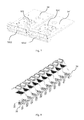
- FIG. 2 shows an embodiment of a trolley with a charging connector being mounted at the bottom thereof.
- FIG. 3 shows the embodiment of the charging connector of this trolley.
- the charging connector 30 comprises insulated housing 35 , two male plugs 31 and 31 ′, and two female sockets 32 and 32 ′. Electrode 33 is provided on male plug 31 , and electrode 33 ′ is provided on male plug 31 ′. Meanwhile, female socket 32 or 32 ′ has an open having a shape corresponding to the shape of male plug 31 or 31 ′ to accommodate the plug.
- the conductive wire of the charging unit accesses charging connector 30 through ports 351 and 351 ′ formed on housing 35 .
- FIG. 4 shows a schematic view of the inner configuration of charging connector 30 .
- two copper-plated electrode slices 34 and 34 ′ being insulated from each other are formed within housing 35 of charging connector 30 .
- Copper-plated electrode slice 34 is connected at one end to electrode 33 , and at another end to reed electrode 321 for trilateral contact.
- Copper-plated electrode slice 34 ′ is connected at one end to electrode 33 ′ and at another end to reed electrode 321 ′ for trilateral contact.
- Each of reed electrodes 321 and 321 ′ comprises a bottom end connected to the copper-plated electrode slice and elastic reeds extending from the middle portion and two sides of the bottom end, respectively.
- Electrodes of two male plugs 31 and 31 ′ are insulated from each other, and so are the electrodes of two female sockets 32 and 32 ′.
- Connecting screw holes 341 and 341 ′ are provided on copper-plated electrode slices 34 and 34 ′ for insertion of the conductive wire of, e.g., a charging unit 101 .
- Connecting screw holes 341 and 341 ′ communicate with ports 351 and 351 ′ of housing 35 to allow insertion of conductive wires.
- the interior of charging connector 30 and housing 35 are preferably integrated, so that the charging connector can be stronger.
- FIG. 5 is a schematic view showing that charging connectors of several trolleys connected in series and coupled to the power supply port when these trolleys are connected to each other in tandem.
- the power supply port is connected with charging connector 30 of the first trolley through a conventional AC/DC conversion unit 50 (such as 1500 W, 2000 W or 3000 W).
- FIGS. 6 a and 6 b show a schematic view of an external configuration of AC/DC conversion unit 50 .
- FIG. 6 a shows the unit with a shell 500
- FIG. 6 b shows the unit without shell 500
- unit 50 further comprises a female socket 501 , an AC/DC conversion module 504 , a switch 502 , and an indicator light 503 , etc.
- AC/DC conversion module can use the commercially available products such as SP-320 series of TAIWAN MINGWEI Co. having a maximum power output of 320 W, and a DC output voltage of DC7.5V, DC12V, DC24V or DC27.5V. The detailed description of this unit is omitted for the sake of avoiding unnecessary obscuring of the substance of the invention.
- Female socket 501 may have the same structure as the female socket of charging connector 30 , as shown in FIG. 7 .
- Female socket 501 has opens 5011 and 5011 ′ corresponding to the shape of the male plug of the charging connector to accommodate the male plug.
- Reed electrodes 521 and 521 ′ having the same structure as reed electrode 321 in the female socket of charging connector 30 are disposed in two opens 5011 and 5011 ′ respectively.
- Reed electrodes 521 and 521 ′ are coupled to the DC output of AC/DC conversion unit 50 respectively through copper-plated electrode slices 54 and 54 ′ which are insulated from each other.
- the current detection unit of each trolley will detect the current of the power bus at the bottom of this trolley.
- the electrode is mounted at the bottom of the trolley, that is, the power bus is disposed at the bottom of the trolley.
- the bus current detection unit controls the operation status of its DC voltage conversion unit according to the detection of the power bus current.
- an indicator “load limit current” is used. This indicator refers to the maximum load current which can be provided by the output of the DC power.
- the DC power can supply power for the load.
- the overload protection will be started in the power supply. Then, the power supply will be shut off so that the load is powered off and cannot be charged. According to the method shown in FIG. 1 , the biggest power bus current will be detected in the charging unit nearest to the DC power.
- the charging process is managed and controlled automatically by the charging management chip according to the preset parameters.
- Different charging management chips may have different preset value. For instance, when the voltage of the battery is lower than 3v, the charging management chip may normally operate in a pre-charging state, and the charging current may be controlled to be about 20% of the charging current of constant current charging by changing the parameters of the peripheral circuit of the charging management chip. When the battery voltage is charged to be higher than 3V, the charging management chip will shift to the constant current charging process automatically. In the constant current charging process, the charging current is kept constant and the magnitude thereof can be preset by setting relevant parameters of the peripheral circuit of the charging management chip,
- the charging management chip When the battery voltage is charged to a preset full voltage (a preset value of lithium battery may be 4.2V), the charging management chip will shift to the constant voltage charging process automatically. In the constant voltage charging process, the charging voltage is constant and the charging current is declined gradually along with the charging process. When the constant voltage charging current is down to about 10% of the constant current charging current, the charging management chip will shift to a stop status and thus the charging process is finished.
- a preset value of lithium battery may be 4.2V
- this current detection unit When a power bus charging current of a trolley detected by the current detection unit of the trolley reaches or is very close to the load limit of the power supply, this current detection unit will output a corresponding signal to shut off the DC voltage unit of this trolley, and the charging current of this trolley will be cut off for the moment, so as to ensure that all trolleys behind this trolley can get sufficient current for charging themselves. If, however, the DC voltage conversion chip of this trolley is started to supply power for the charging management circuit thereof at this time, that is, to charge this trolley, the charging current thereof will be superimposed to the total charging current of all the trolleys behind this trolley, which will render the bus current exceeding the load limit of the DC power. Under such a situation, the overload protection of the DC power is triggered and the power supply is shut off, causing a failure of charging for all trolleys connected to be charged.
- the bus current of this trolley will be declined in succession.
- the charging current of all trolleys behind this trolley runs through metal electrodes of the power bus of this trolley, thus the change of charging current of the trolleys in the rear can be detected by the bus current detection unit of the trolley in the front.
- the current of the power bus running through the front trolley has no change, whilst during the constant voltage charging process of a certain trolley, the charging current will be declined gradually along with the charging process and the charging thereof will be detected by the bus current detection unit of the trolley in front of this trolley.
- this bus detection unit When the power bus current (not the charging current) of this trolley detected by the bus current detection unit thereof lowers to a current being capable of charging this trolley, this bus detection unit will output a corresponding signal to control the DC voltage conversion thereof to operate in a DC voltage reduction conversion state, so that the charging management circuit (as indicated by reference sign 1013 , 1023 or 1033 in FIG. 1 ) is provided with a +5V power to control the process of battery charging.
- Charging management circuits 1012 , 1023 and 1033 in FIG. 1 can be disposed inside an electronic equipment of the armrest portion of the trolley for control of the power supply to the rechargeable battery of this trolley.
- AC/DC conversion unit 50 can output 5V to 6V directly so that lithium battery can be charged directly.
- the DC voltage reduction chip with EN is not necessary for each trolley, which can be replaced with a controlled electronic switch.
Landscapes
- Engineering & Computer Science (AREA)
- Power Engineering (AREA)
- Transportation (AREA)
- Mechanical Engineering (AREA)
- Life Sciences & Earth Sciences (AREA)
- Sustainable Development (AREA)
- Sustainable Energy (AREA)
- Chemical & Material Sciences (AREA)
- Combustion & Propulsion (AREA)
- Charge And Discharge Circuits For Batteries Or The Like (AREA)
- Health & Medical Sciences (AREA)
- Handcart (AREA)
- Electric Propulsion And Braking For Vehicles (AREA)
- Details Of Connecting Devices For Male And Female Coupling (AREA)
- Arrangement Or Mounting Of Propulsion Units For Vehicles (AREA)
- Epidemiology (AREA)
- Pain & Pain Management (AREA)
- Physical Education & Sports Medicine (AREA)
- Rehabilitation Therapy (AREA)
- Animal Behavior & Ethology (AREA)
- General Health & Medical Sciences (AREA)
- Public Health (AREA)
- Veterinary Medicine (AREA)
Abstract
Description
Claims (10)
Applications Claiming Priority (4)
Application Number | Priority Date | Filing Date | Title |
---|---|---|---|
CN201310009334 | 2013-01-10 | ||
CN201310009334.0 | 2013-01-10 | ||
CN201310009334.0A CN103580297B (en) | 2013-01-10 | 2013-01-10 | Mobile device and charging method thereof |
PCT/CN2014/070076 WO2014108046A1 (en) | 2013-01-10 | 2014-01-03 | Mobile device and charging method therefor |
Publications (2)
Publication Number | Publication Date |
---|---|
US20150349557A1 US20150349557A1 (en) | 2015-12-03 |
US9780585B2 true US9780585B2 (en) | 2017-10-03 |
Family
ID=50051475
Family Applications (1)
Application Number | Title | Priority Date | Filing Date |
---|---|---|---|
US14/760,329 Expired - Fee Related US9780585B2 (en) | 2013-01-10 | 2014-01-03 | Movable device and method of charging the same |
Country Status (8)
Country | Link |
---|---|
US (1) | US9780585B2 (en) |
EP (1) | EP2793350B1 (en) |
JP (2) | JP6463694B2 (en) |
KR (1) | KR101727517B1 (en) |
CN (1) | CN103580297B (en) |
ES (1) | ES2655239T3 (en) |
HK (1) | HK1190234A1 (en) |
WO (1) | WO2014108046A1 (en) |
Cited By (1)
Publication number | Priority date | Publication date | Assignee | Title |
---|---|---|---|---|
US10384556B1 (en) * | 2018-03-12 | 2019-08-20 | Honda Motor Co., Ltd. | Multi-vehicle type device having battery packs |
Families Citing this family (15)
Publication number | Priority date | Publication date | Assignee | Title |
---|---|---|---|---|
CN103580297B (en) | 2013-01-10 | 2015-11-18 | 无锡知谷网络科技有限公司 | Mobile device and charging method thereof |
CN203103711U (en) * | 2013-01-10 | 2013-07-31 | 无锡知谷网络科技有限公司 | Electric connector and mobile equipment |
CN204348993U (en) * | 2015-01-13 | 2015-05-20 | 无锡知谷网络科技有限公司 | A kind of charge connector and there is the handcart of this charge connector |
CN105552673A (en) * | 2016-02-05 | 2016-05-04 | 无锡知谷网络科技有限公司 | Connector, safety control device, charging device and mobile device |
CN105720656B (en) * | 2016-04-15 | 2019-06-11 | 无锡知谷网络科技有限公司 | Charge control method, battery charge controller and the mobile device of multiple charging units |
CN109017950A (en) * | 2017-06-09 | 2018-12-18 | 江苏弘冠智能科技有限公司 | Multifunctional shopping cart |
JP7040054B2 (en) * | 2018-01-26 | 2022-03-23 | トヨタ自動車株式会社 | How to charge an electric self-supporting moving body |
JP2019129684A (en) * | 2018-01-26 | 2019-08-01 | トヨタ自動車株式会社 | Charging method for electrically-driven autonomous mobile body |
JP6522843B1 (en) * | 2018-10-09 | 2019-05-29 | 株式会社アイ・ディー・エクス | Battery charging system and control method thereof |
US11518263B2 (en) | 2019-02-08 | 2022-12-06 | Lg Electronics Inc. | Power supply device supplying power to multiple carts, cart, and method for charging cart |
CN113348105A (en) * | 2019-02-08 | 2021-09-03 | Lg电子株式会社 | Power supply device for supplying power to multiple trolleys, trolley and charging method of trolley |
JP7286363B2 (en) | 2019-03-22 | 2023-06-05 | 東芝テック株式会社 | Power receiving system and power feeding system |
WO2020235701A1 (en) * | 2019-05-20 | 2020-11-26 | 엘지전자 주식회사 | Cart robot having charging function |
CN110783995A (en) * | 2019-11-21 | 2020-02-11 | 广州织点智能科技有限公司 | Controllable overlapping charging system, method, device, equipment and storage medium |
WO2024021047A1 (en) * | 2022-07-29 | 2024-02-01 | Maplebear Inc. | Stackable charging device for shopping carts with onboard computing systems |
Citations (18)
Publication number | Priority date | Publication date | Assignee | Title |
---|---|---|---|---|
US3652103A (en) | 1970-03-23 | 1972-03-28 | Stuart P Higgs | Automatic brake for a shopping cart |
EP1153816A1 (en) | 1999-11-16 | 2001-11-14 | Martin Blas Gonzalez Serrano | Self-propelled cart usable in supermarkets and the like |
WO2004042681A1 (en) | 2002-11-08 | 2004-05-21 | Marcelo Machado Coelho | Trolley having an illuminated display |
US20050225305A1 (en) | 2004-04-09 | 2005-10-13 | Maxwell Technologies, Inc. | Capacitor start-up apparatus and method with fail safe short circuit protection |
US20060264120A1 (en) * | 2005-04-29 | 2006-11-23 | Sprn Licensing Srl | Portable information terminal mountable on shopping cart and removable memory device usable with same |
CN201345471Y (en) | 2008-11-21 | 2009-11-11 | 深圳市好易通科技有限公司 | Freely combinable seat type charger |
CN101752889A (en) | 2010-01-13 | 2010-06-23 | 钟馨稼 | Electric vehicle quick charge system |
CN102005797A (en) | 2010-12-08 | 2011-04-06 | 夏正奎 | Active self-management charging device of lithium-ion power battery |
US20110084649A1 (en) * | 2009-10-09 | 2011-04-14 | Tai-Her Yang | Power charging device with charge saturation disconnector through electromagnetic force release |
CN201839051U (en) | 2010-11-05 | 2011-05-18 | 深圳奥士达电子有限公司 | Charger and charger component |
US20110133693A1 (en) * | 2009-12-17 | 2011-06-09 | Richard Lowenthal | Method and apparatus for electric vehicle charging station load management in a residence |
KR20110100431A (en) | 2010-03-04 | 2011-09-14 | 한국과학기술원 | Cart auto-charging system and auto-charging cart |
CN202159803U (en) | 2011-08-26 | 2012-03-07 | 现代照明电气(惠州)有限公司 | Socket conducting strip |
KR20120031768A (en) | 2010-09-27 | 2012-04-04 | 엘지이노텍 주식회사 | Locking device having power supply function in shopping cart |
CN202197136U (en) | 2011-07-13 | 2012-04-18 | 胡逸柯 | Charging apparatus |
CN102437607A (en) | 2011-12-06 | 2012-05-02 | 北京恒泰源丰信息技术有限公司 | Linkable Charger |
CN203071613U (en) | 2013-01-10 | 2013-07-17 | 无锡知谷网络科技有限公司 | Rechargeable mobile device |
CN103580297B (en) | 2013-01-10 | 2015-11-18 | 无锡知谷网络科技有限公司 | Mobile device and charging method thereof |
Family Cites Families (4)
Publication number | Priority date | Publication date | Assignee | Title |
---|---|---|---|---|
JPH05316607A (en) * | 1992-05-11 | 1993-11-26 | Yaskawa Electric Corp | Motor-driven truck and charging method therefor |
JP2928431B2 (en) * | 1993-01-13 | 1999-08-03 | 富士通株式会社 | Auxiliary battery device and charge / discharge control method |
JP5081780B2 (en) * | 2008-09-30 | 2012-11-28 | 本田技研工業株式会社 | Electric vehicle charging control device |
TWM421641U (en) * | 2011-08-09 | 2012-01-21 | ming-xiang Ye | Back discharging protection sleeve for handset device |
-
2013
- 2013-01-10 CN CN201310009334.0A patent/CN103580297B/en active Active
-
2014
- 2014-01-03 WO PCT/CN2014/070076 patent/WO2014108046A1/en active Application Filing
- 2014-01-03 US US14/760,329 patent/US9780585B2/en not_active Expired - Fee Related
- 2014-01-03 JP JP2015551969A patent/JP6463694B2/en not_active Expired - Fee Related
- 2014-01-03 EP EP14711673.5A patent/EP2793350B1/en not_active Not-in-force
- 2014-01-03 KR KR1020157021593A patent/KR101727517B1/en active IP Right Grant
- 2014-01-03 ES ES14711673.5T patent/ES2655239T3/en active Active
- 2014-03-31 HK HK14103057.8A patent/HK1190234A1/en not_active IP Right Cessation
-
2018
- 2018-09-03 JP JP2018164289A patent/JP2019009996A/en active Pending
Patent Citations (19)
Publication number | Priority date | Publication date | Assignee | Title |
---|---|---|---|---|
US3652103A (en) | 1970-03-23 | 1972-03-28 | Stuart P Higgs | Automatic brake for a shopping cart |
EP1153816A1 (en) | 1999-11-16 | 2001-11-14 | Martin Blas Gonzalez Serrano | Self-propelled cart usable in supermarkets and the like |
WO2004042681A1 (en) | 2002-11-08 | 2004-05-21 | Marcelo Machado Coelho | Trolley having an illuminated display |
US20050225305A1 (en) | 2004-04-09 | 2005-10-13 | Maxwell Technologies, Inc. | Capacitor start-up apparatus and method with fail safe short circuit protection |
US20060264120A1 (en) * | 2005-04-29 | 2006-11-23 | Sprn Licensing Srl | Portable information terminal mountable on shopping cart and removable memory device usable with same |
CN201345471Y (en) | 2008-11-21 | 2009-11-11 | 深圳市好易通科技有限公司 | Freely combinable seat type charger |
US20110084649A1 (en) * | 2009-10-09 | 2011-04-14 | Tai-Her Yang | Power charging device with charge saturation disconnector through electromagnetic force release |
US20110133693A1 (en) * | 2009-12-17 | 2011-06-09 | Richard Lowenthal | Method and apparatus for electric vehicle charging station load management in a residence |
CN101752889A (en) | 2010-01-13 | 2010-06-23 | 钟馨稼 | Electric vehicle quick charge system |
KR20110100431A (en) | 2010-03-04 | 2011-09-14 | 한국과학기술원 | Cart auto-charging system and auto-charging cart |
KR20120031768A (en) | 2010-09-27 | 2012-04-04 | 엘지이노텍 주식회사 | Locking device having power supply function in shopping cart |
CN201839051U (en) | 2010-11-05 | 2011-05-18 | 深圳奥士达电子有限公司 | Charger and charger component |
CN102005797A (en) | 2010-12-08 | 2011-04-06 | 夏正奎 | Active self-management charging device of lithium-ion power battery |
CN202197136U (en) | 2011-07-13 | 2012-04-18 | 胡逸柯 | Charging apparatus |
CN202159803U (en) | 2011-08-26 | 2012-03-07 | 现代照明电气(惠州)有限公司 | Socket conducting strip |
CN102437607A (en) | 2011-12-06 | 2012-05-02 | 北京恒泰源丰信息技术有限公司 | Linkable Charger |
CN203071613U (en) | 2013-01-10 | 2013-07-17 | 无锡知谷网络科技有限公司 | Rechargeable mobile device |
CN103580297B (en) | 2013-01-10 | 2015-11-18 | 无锡知谷网络科技有限公司 | Mobile device and charging method thereof |
KR101727517B1 (en) | 2013-01-10 | 2017-04-17 | 치구 인터랙티브 테크놀로지 씨오., 엘티디. | Mobile device and charging method therefor |
Non-Patent Citations (1)
Title |
---|
International Search Report Application No. PCT/CN2014/070076 Completed Mar. 17, 2014; dated Mar. 27, 2014 5 pages. |
Cited By (2)
Publication number | Priority date | Publication date | Assignee | Title |
---|---|---|---|---|
US10384556B1 (en) * | 2018-03-12 | 2019-08-20 | Honda Motor Co., Ltd. | Multi-vehicle type device having battery packs |
US20190275896A1 (en) * | 2018-03-12 | 2019-09-12 | Honda Motor Co., Ltd. | Multi-vehicle type device having battery packs |
Also Published As
Publication number | Publication date |
---|---|
JP2019009996A (en) | 2019-01-17 |
JP6463694B2 (en) | 2019-02-06 |
EP2793350A1 (en) | 2014-10-22 |
CN103580297B (en) | 2015-11-18 |
EP2793350B1 (en) | 2017-10-18 |
KR101727517B1 (en) | 2017-04-17 |
ES2655239T3 (en) | 2018-02-19 |
KR20150106434A (en) | 2015-09-21 |
US20150349557A1 (en) | 2015-12-03 |
CN103580297A (en) | 2014-02-12 |
WO2014108046A1 (en) | 2014-07-17 |
HK1190234A1 (en) | 2014-06-27 |
JP2016510584A (en) | 2016-04-07 |
EP2793350A4 (en) | 2015-08-12 |
Similar Documents
Publication | Publication Date | Title |
---|---|---|
US9780585B2 (en) | Movable device and method of charging the same | |
EP3185388B1 (en) | Battery control method and apparatus, and battery pack | |
US10250059B2 (en) | Charging circuit for battery-powered device | |
CN102638081B (en) | Smart matrix battery charging-discharging managing system and managing method | |
US20170279273A1 (en) | Electrical load management system and method | |
US8816644B2 (en) | Interrupting the charging status of a rechargeable battery | |
US20210343993A1 (en) | Battery power management for a battery backup unit (bbu) shelf | |
US8286020B2 (en) | Power supply and protection method thereof | |
US20240055878A1 (en) | Modular battery pack charging system and method of operating the same | |
US20140091752A1 (en) | USB Charging System | |
US20140035746A1 (en) | Integrated charger and alarm unit | |
CN203071613U (en) | Rechargeable mobile device | |
TWI790453B (en) | Rechargeable battery pack and handheld vacuum cleaning device | |
US20230097967A1 (en) | Charger including multiple adjustable power sources | |
CN214479810U (en) | Battery management system and device | |
CN206960628U (en) | A kind of integrated data acquisition unit for battery management system | |
CN207765973U (en) | A kind of battery charge controller of charging cabinet | |
CN115811116A (en) | Self-adaptive power supply management system and method and energy storage power supply | |
US20240072385A1 (en) | Power supply including a touch safe power supply core | |
CN216649278U (en) | Trade electric cabinet based on cluster charging system | |
CN203218930U (en) | Intelligent mobile power supply | |
CN202957624U (en) | Modularized rechargeable power supply system | |
CN103001287A (en) | Balance maintenance charging device and method for battery pack | |
KR20140114130A (en) | Battery pack, Method for charging/discharging the same | |
CN103607005A (en) | Portable direct-charging cell |
Legal Events
Date | Code | Title | Description |
---|---|---|---|
AS | Assignment |
Owner name: CHIGOO INTERACTIVE TECHNOLOGY CO., LTD., CHINA Free format text: ASSIGNMENT OF ASSIGNORS INTEREST;ASSIGNORS:CHEN, TAO;LAN, WEIJIAN;PAN, CHUANRONG;AND OTHERS;REEL/FRAME:036091/0656 Effective date: 20150703 |
|
STCF | Information on status: patent grant |
Free format text: PATENTED CASE |
|
FEPP | Fee payment procedure |
Free format text: MAINTENANCE FEE REMINDER MAILED (ORIGINAL EVENT CODE: REM.); ENTITY STATUS OF PATENT OWNER: SMALL ENTITY |
|
LAPS | Lapse for failure to pay maintenance fees |
Free format text: PATENT EXPIRED FOR FAILURE TO PAY MAINTENANCE FEES (ORIGINAL EVENT CODE: EXP.); ENTITY STATUS OF PATENT OWNER: SMALL ENTITY |
|
STCH | Information on status: patent discontinuation |
Free format text: PATENT EXPIRED DUE TO NONPAYMENT OF MAINTENANCE FEES UNDER 37 CFR 1.362 |
|
FP | Lapsed due to failure to pay maintenance fee |
Effective date: 20211003 |