US9779902B2 - Configurable modular intelligent electronic overload device and system with embedded programming tool - Google Patents
Configurable modular intelligent electronic overload device and system with embedded programming tool Download PDFInfo
- Publication number
- US9779902B2 US9779902B2 US14/078,196 US201314078196A US9779902B2 US 9779902 B2 US9779902 B2 US 9779902B2 US 201314078196 A US201314078196 A US 201314078196A US 9779902 B2 US9779902 B2 US 9779902B2
- Authority
- US
- United States
- Prior art keywords
- intelligent electronic
- electronic overload
- control module
- user
- memory device
- Prior art date
- Legal status (The legal status is an assumption and is not a legal conclusion. Google has not performed a legal analysis and makes no representation as to the accuracy of the status listed.)
- Active, expires
Links
- 238000004891 communication Methods 0.000 claims description 49
- 230000009471 action Effects 0.000 claims description 5
- 230000006870 function Effects 0.000 description 31
- 238000000034 method Methods 0.000 description 26
- 230000008569 process Effects 0.000 description 18
- 238000012800 visualization Methods 0.000 description 16
- 239000007858 starting material Substances 0.000 description 7
- 238000005516 engineering process Methods 0.000 description 6
- 238000009434 installation Methods 0.000 description 4
- 239000004020 conductor Substances 0.000 description 3
- 238000001514 detection method Methods 0.000 description 3
- 238000012986 modification Methods 0.000 description 3
- 230000004048 modification Effects 0.000 description 3
- 239000011668 ascorbic acid Substances 0.000 description 2
- 239000003086 colorant Substances 0.000 description 2
- 230000008878 coupling Effects 0.000 description 2
- 238000010168 coupling process Methods 0.000 description 2
- 238000005859 coupling reaction Methods 0.000 description 2
- 230000000873 masking effect Effects 0.000 description 2
- 230000000737 periodic effect Effects 0.000 description 2
- 238000012545 processing Methods 0.000 description 2
- 230000009286 beneficial effect Effects 0.000 description 1
- 230000005540 biological transmission Effects 0.000 description 1
- 230000008859 change Effects 0.000 description 1
- 238000004590 computer program Methods 0.000 description 1
- 238000013461 design Methods 0.000 description 1
- 238000011161 development Methods 0.000 description 1
- 230000020169 heat generation Effects 0.000 description 1
- 238000012423 maintenance Methods 0.000 description 1
- 238000004519 manufacturing process Methods 0.000 description 1
- 230000005055 memory storage Effects 0.000 description 1
- 238000011160 research Methods 0.000 description 1
- 238000000926 separation method Methods 0.000 description 1
- 239000007787 solid Substances 0.000 description 1
- 239000004334 sorbic acid Substances 0.000 description 1
Images




Classifications
-
- H—ELECTRICITY
- H01—ELECTRIC ELEMENTS
- H01H—ELECTRIC SWITCHES; RELAYS; SELECTORS; EMERGENCY PROTECTIVE DEVICES
- H01H71/00—Details of the protective switches or relays covered by groups H01H73/00 - H01H83/00
-
- H—ELECTRICITY
- H01—ELECTRIC ELEMENTS
- H01H—ELECTRIC SWITCHES; RELAYS; SELECTORS; EMERGENCY PROTECTIVE DEVICES
- H01H71/00—Details of the protective switches or relays covered by groups H01H73/00 - H01H83/00
- H01H2071/006—Provisions for user interfaces for electrical protection devices
-
- H—ELECTRICITY
- H02—GENERATION; CONVERSION OR DISTRIBUTION OF ELECTRIC POWER
- H02H—EMERGENCY PROTECTIVE CIRCUIT ARRANGEMENTS
- H02H3/00—Emergency protective circuit arrangements for automatic disconnection directly responsive to an undesired change from normal electric working condition with or without subsequent reconnection ; integrated protection
- H02H3/006—Calibration or setting of parameters
-
- H—ELECTRICITY
- H02—GENERATION; CONVERSION OR DISTRIBUTION OF ELECTRIC POWER
- H02H—EMERGENCY PROTECTIVE CIRCUIT ARRANGEMENTS
- H02H7/00—Emergency protective circuit arrangements specially adapted for specific types of electric machines or apparatus or for sectionalised protection of cable or line systems, and effecting automatic switching in the event of an undesired change from normal working conditions
- H02H7/08—Emergency protective circuit arrangements specially adapted for specific types of electric machines or apparatus or for sectionalised protection of cable or line systems, and effecting automatic switching in the event of an undesired change from normal working conditions for dynamo-electric motors
- H02H7/0822—Integrated protection, motor control centres
Definitions
- the subject matter disclosed herein relates generally to overload relays, and, more particularly, to a modular electronic overload device adapted to allow for easier commissioning and replacement.
- Overload relays are current sensitive relays that can be used to disconnect power from equipment when an overload or other sensed condition exists. They are normally used in conjunction with an electromechanical contactor, and are designed to protect an electric motor or other electronic devices.
- the contactor provides three contacts, one associated with each of up to three phases of power, that are closed by an electromagnetically operated contactor coil.
- the overload relay includes current sensing elements that are wired in series with the three phases passing through the contactor to the motor. In this way, the overload relay can monitor current flowing in the three phases through the contactor, and based on current magnitude and duration, may interrupt the current flow through the contactor coil circuit to open the contactor contacts when an overload occurs.
- the overload relay includes a contact or contacts that can be used to control the contactor coil and/or provide a signal indicating an overload or other sensed condition.
- One difficulty associated with overload relays in general is the complexity in commissioning a motor control panel where multiple motor control circuits are required.
- a system integrator may be required to configure a local human-machine interface device (hereinafter “HMI”), and/or a network device to properly configure an intelligent electronic overload device. To perform the required configuration, the system integrator may require a personal computer.
- HMI human-machine interface device
- Another difficulty associated with intelligent electronic overload devices is the time required to configure a replacement intelligent electronic overload device.
- maintenance personnel often require access to a personal computer in order to configure a replacement intelligent electronic overload device, to which they may not have immediate access to when needed.
- Lack of access to a properly configured personal computer combined with the above mentioned difficulty associated with configuring complex intelligent electronic overload devices, can result in unnecessary downtime as well as lost production time when an intelligent electronic overload device must be replaced.
- overload device is designed for only a limited current range, and, possibly, a limited, fixed set of functional options. If you are a manufacturer, you want to offer a full product line, which means offering a large variety of overload relays that operate at their respective currents.
- an integrator or an original equipment manufacturer (“OEM”) using overload relays needs to have a large selection of overload relays available to meet the needs of the designed application. Attempts to accommodate overload relays to operate in a wider range of applications can result in increased size, cost, and heat generation.
- intelligent electronic overload devices with many available options have multiple product configuration files to identify the specific options that were selected for that system. This could result in thousands of different configuration files which can be very difficult to manage. A large number of different configuration files can also create significant complexity for the creation of collateral application software as well.
- intelligent devices such as intelligent electronic overload devices can often be used as remote control modules. This allows a user to utilize the power of the devices to configure the I/O on the device for specific applications. This is often done using an industrial automation programming architecture such as RSLOGIX from Rockwell Automation. However, this often required a sophisticated user with a programming device, such as a personal computer with the necessary programming software, to program the intelligent device. However, often the devices were configured to correspond with commonly used application configurations. In these instances, the ability for a user to quickly configure an intelligent device such as an intelligent electronic overload device for a common application could significantly reduce installation and commissioning time for industrial automation systems.
- an intelligent electronic overload device can have a single configuration file, such as an EDS file, with a common set of user-selectable parameters contained within the intelligent electronic overload device.
- an intelligent electronic overload device that can have embedded software function blocks that a user can select to place the device into a desired operational mode without a user being required to program the device, as has been done traditionally.
- the present embodiments overcomes the aforementioned problems by providing a modular intelligent electronic overload device that requires only a single configuration file to describe the device with all of the available options. Furthermore, the modular intelligent electronic overload device contains embedded application files that provide commonly used control algorithms into the non-volatile memory of the modular intelligent electronic overload device that can be accessed by a user to configure the device without the need for a personal computer. Finally, the modular intelligent electronic overload device configuration parameters can be stored to virtual non-volatile memory contained in an associated user interface device, allowing for easy replacement of the modular intelligent electronic overload device.
- Embodiments of the present invention include an integrated function block technology, a single EDS file technology, and an off-board memory storing the configuration parameters.
- embodiments of the above technologies include a modular intelligent overload system.
- the system comprises a control module and a communication module; the control module having a memory device, the memory device containing a plurality of function blocks; the communication module in electrical communication with the control module; and the communication module additionally in electrical communication with a configuration tool, wherein the configuration tool is used by a user to select a single function block from the plurality of function blocks.
- the embodiment further comprising an external memory device, the external memory device capable of storing the function blocks stored in the control module memory device.
- the external memory device is located on a user interface device electrically coupled to the electronic overload device.
- embodiments of the present invention include a modular intelligent electronic overload system.
- the system comprises a control module, a communication module and a configuration tool.
- the control module having a memory device, the memory device comprising a configuration file and a plurality of status bits; the communication module in electronic communication with the control module; and the configuration tool having an interface allowing a user to select at least one of a plurality of parameters, wherein the configuration tool sets the plurality of status bits to correspond with the at least one of the plurality of parameters selected by the user.
- the embodiment further comprising an external memory device, the external memory device capable of storing an identical copy of the plurality of parameters stored in the control module memory device.
- the external memory device is located on a user interface device electrically coupled to the electronic overload device.
- embodiments of the present invention include a modular intelligent electronic overload system.
- the system comprises a control module, a communication module, a configuration tool, and a user interface device.
- the control module having a memory device, the memory device configured to store at least a plurality of function blocks, a configuration file, and a plurality of status bits; the communication module in electrical communication with the control module; the configuration tool configured to allow a user to select at least one of a plurality of parameters, wherein the configuration tool sets the plurality of status bits to correspond with the at least one of the plurality of parameters selected by the user; the configuration tool further configured to be used by a user to select a single function block from the plurality of function blocks; and the user interface device being electrically coupled to the control module, the user interface having a memory device, the user interface memory device configured to copy the plurality of parameters located in the control module memory device
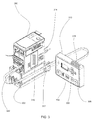
- FIG. 1 is a perspective exploded view of a modular intelligent electronic overload device, according to embodiments of the present invention
- FIG. 2 is a process flow-chart illustrating the configuration of a modular intelligent electronic overload device
- FIG. 3 is a perspective view of a modular intelligent electronic overload device coupled to a user interface device
- FIG. 4 is a process flow-chart illustrating the process of configuring a modular intelligent electronic overload device based on a selected operating mode
- FIG. 5 is an exemplary schematic view of an embedded function block.
- connection means that one element/feature is directly or indirectly connected to another element/feature, and not necessarily electrically or mechanically.
- coupled means that one element/feature is directly or indirectly coupled to another element/feature, and not necessarily electrically or mechanically.
- Embodiments of the invention may be described herein in terms of functional and/or logical block components and various processing steps. It should be appreciated that such block components may be realized by any number of hardware, software, and/or firmware components configured to perform the specified functions. For example, an embodiment may employ various integrated circuit components, e.g., digital signal processing elements, logic elements, diodes, etc., which may carry out a variety of functions under the control of one or more processors or other control devices. Other embodiments may employ program code, or code in combination with other circuit components.
- a first portion of the modular intelligent electronic overload device can be a sensing module having a first housing supporting integrated phase current conductors and load side power terminals.
- the integrated phase current conductors conduct load current from the contactor (line side of the modular intelligent electronic overload device) through the modular intelligent electronic overload device to the load side terminals, and current sensing devices and associated sensing circuitry monitors the current in the phase current conductors to produce a signal proportional to the current.
- the sensing module includes a sensing module electrical connector extending from a front side of the first housing and communicating with the sensing module circuitry.
- a second portion of the modular intelligent electronic overload device can be a control module having a second housing attachable to the front side of the sensing module.
- the control module can include a front side electrical connector located on a front side of the control module and a back side electrical connector located on a back side of the control module.
- the back side electrical connector can mate with the sensing module electrical connector when the control module is coupled to the front side of the sensing module housing.
- Circuitry within the control module can communicate with the sensing module circuitry to augment its function.
- the control module can also contain a memory storage for storing information in the control module.
- the second housing of the control module can include terminals providing an interface for power and input and output signals.
- a third portion of the modular intelligent electronic overload device can be a communication module having a third housing attachable to the front side of the control module.
- the control module electrical connector located on the front side of the control module can mate with a communication module electrical connector when the communication module is coupled to the front wall of the control module housing.
- Circuitry within the communication module can communicate with the control module circuitry and the sensing module circuitry to augment its function. Use of the communication module to provide an optional network connection to an overload relay can reduce the cost of the sensing module and/or control module.
- a physical separation of functions of the modules can be incorporated into many electronic devices, including a modular intelligent electronic overload device, allowing a variety of electronic overload devices of different functions to be offered in a cost-effective basis.
- the electrical connectors between the modules allows division of functions to be accomplished with minimal interface cost.
- circuitry described herein can provide functions including motor jam detection, current imbalance detection, and ground fault current detection, for example.
- the circuitry can provide remote reset or trip of the overload relay.
- Embodiments of the invention can provide remote resetting as an optional feature, thereby reducing the cost of the modular intelligent electronic overload device.
- any of the modular intelligent electronic overload devices described herein can be configured with a variety of parameters. These parameters may include, but are not limited to, current ranges, allowable overload percentages, communication protocols, phase imbalance tolerance, etc.
- FIG. 1 shows an exploded view of a modular intelligent electronic overload device 100 .
- the modular intelligent electronic overload device 100 can have a modular design and can be comprised of a communication module 102 , a control module 104 and a sensing module 106 .
- the control module 104 can have input/output (hereinafter “I/O”) connections 108 that can be used for interfacing the modular intelligent electronic overload device 100 with other devices.
- I/O input/output
- the control module 104 can also contain at least one memory device 110 .
- the memory device 110 can be volatile or non-volatile.
- the communication module 102 can interface to the modular intelligent electronic overload device 100 with various network protocols.
- Example protocols that the communication module 102 can interface with can be EthernetIP, DeviceNet, Profibus or other network protocols for use in the required application.
- the sensing module 106 can be used to sense a current flow in a motor application. Furthermore, in one embodiment the sensing module 106 and the communication module 102 can both electrically communicate with the control module 104 and vice versa.
- An example intelligent device configuration file can be an Electronic Data Sheet (“EDS”) file for use on a LOGIX based control system from Rockwell Automation.
- EDS file can contain all the options and parameters for an intelligent device and it can often be required to have an EDS file for each unique intelligent device. Users can access EDS files for downloading into a modular intelligent electronic overload device 100 or other intelligent device in multiple ways. For example, EDS files might be accessed via an internet web site, a CD-ROM, a flash memory, or other device or protocol suitable for data transmission.
- a visualization device 118 may be utilized to view and configure intelligent system components such as a modular intelligent electronic overload device 100 .
- a visualization device 118 may be a PANELVIEW from Rockwell Automation or other visualization device 118 .
- the visualization device 118 may require a specific visualization configuration file to be able to adequately interface with an intelligent device.
- This visualization configuration file may be a “Faceplate” type file as used in LOGIX based control system from Rockwell Automation.
- a unique visualization configuration file may be required for each unique intelligent device configuration file 114 .
- FIG. 2 illustrates an embodiment of the described technology which allows for a single intelligent device configuration file 114 .
- a user can configure a new intelligent device using a configuration tool 112 , 113 .
- the configuration tool 113 can be a computer program capable of being executed on a personal computer.
- the configuration tool 112 can be embedded in a specific device for configuring intelligent devices.
- the configuration tool 112 can utilize a dedicated communication link 122 to the intelligent device.
- the intelligent device is a modular intelligent electronic overload device 100 .
- the modular intelligent electronic overload device 100 can have multiple options. These options can include, but are not limited to, communication module 102 types, sensing module 106 types, additional I/O modules, and user interface devices, among others.
- a user can select the options that are installed on the modular intelligent electronic overload device 100 using the configuration tool 112 , 113 .
- the configuration tool 112 , 113 can communicate the selected options to a configuration file 114 for the modular intelligent electronic overload device 100 .
- the configuration file 114 can be embedded in the memory device 110 of the control module 104 of the modular intelligent electronic overload device 100 .
- the configuration file 114 can contain a plurality of status bits 116 that correspond to each unique option available for the modular intelligent electronic overload device 100 .
- the status bits 116 can be separate from the configuration file 114 .
- the status bits can 116 can be contained in the real-time data presented to the modular intelligent electronic overload device.
- the configuration file 114 can set the plurality of status bits 116 that correspond to the selected options of the modular intelligent electronic overload device 100 .
- the modular intelligent electronic overload device 100 can determine if the configuration file 114 has been set to ignore the plurality of status bits 116 .
- the modular intelligent electronic overload device 100 can periodically evaluate if each of the unique options are present on the modular intelligent electronic overload device 100 .
- the control module 104 can perform the periodic checking to determine if other options are installed.
- the configuration tool 112 , 113 can perform the periodic checking.
- the modular intelligent electronic overload device 100 can compare the options selected in the configuration file 114 to the plurality of status bits 116 .
- the intelligent electronic overload device 100 can perform an appropriate mismatch action based on the configuration file 114 not matching the plurality of status bits.
- the mismatch action can be to ignore the mismatch.
- the mismatch action can be to trip the modular intelligent electronic overload device 100 .
- the mismatch action can be to have the modular intelligent electronic overload device 100 present a warning to a user.
- the warning can be displayed by the modular intelligent electronic overload device 100 .
- the warning can be presented via a user interface device 310 .
- the warning can be presented via a visualization device 118 .
- the visualization device 118 can also allow a user to modify writeable parameters of the modular intelligent electronic overload device 100 based on status bits 116 in the configuration file 114 .
- the bits contained in the configuration file 114 that correspond to non-selected options can be masked. This masking can allow a single configuration file 114 to be used for the modular intelligent overload device 100 with multiple options. The masking of the bits associated with the non-selected options can allow the user to be able to have access only to parameters that are available for the selected options contained in the modular intelligent electronic overload device 100 when configuring the device for the application.
- the parameters can be stored in the memory device 110 of the control module 104 of the modular intelligent electronic overload device 100 .
- a user may not have a configuration tool available to configure the replacement modular intelligent electronic overload device 100 .
- this technology presents a system and method to store the configuration file 114 in a separate device that can be accessed by a modular intelligent electronic overload device 100 without the need for a configuration tool such as a personal computer or other dedicated programming device.
- FIG. 3 contains a modular intelligent electronic overload device 300 and a user interface device 310 .
- the user interface device can be a device such as an E300 or E200 type operator station from Rockwell Automation.
- the modular intelligent electronic overload device 300 and the user interface device 310 can be electronically connected via a communication link 302 .
- the communication link 302 can be established using a communication port 320 in a control module 314 of the modular intelligent electronic overload device 300 .
- the modular intelligent electronic overload device 300 and the user interface device 310 can communicate via the communication link 302 using a communication protocol.
- this communication protocol can be a two-wire serial communication protocol.
- the communication protocol can be a version of DEVICELOGIX from Rockwell Automation.
- any communication protocol known in the art could be also used.
- a user interface device 310 can be connected to the modular intelligent electronic overload device 300 .
- the user interface device 310 can be an E300 operator station from Rockwell Automation.
- the user interface device 310 can contain a memory device 318 .
- the user interface device 310 can also contain multiple user input devices 304 - 308 .
- a user can then actuate a first user input device 304 and a second user input device 306 simultaneously for a pre-determined time, although other methods of actuation are possible.
- the pre-determined time can be three seconds, although more or less time is contemplated.
- the user interface device 310 can transmit a write command to the modular intelligent electronic overload device 300 .
- the modular intelligent electronic overload device 300 receiving the write command from the user interface device 310 , can transmit a set of writeable configuration parameters to the user interface device 310 .
- the user interface device 310 can then store the modular intelligent overload device 300 configuration parameters in the memory device 318 .
- the user interface device 310 can store an identical copy of the configuration parameters stored in the modular intelligent overload device 300 .
- the writeable configuration parameters can be a plurality of function blocks 120 .
- the user interface device 310 may also contain a user feedback device 312 .
- the user feedback device 312 can be an LED.
- the user feedback device 312 can be a multi-color LED. In other embodiments, a plurality of LEDs can be used.
- the user feedback device 312 can communicate the status of the user interface device 310 receiving the configuration parameters from the modular intelligent electronic overload device 300 .
- the user feedback device 312 can communicate that the modular intelligent electronic overload device 300 is writing configuration parameters to the user feedback device 312 .
- the user feedback device can blink between alternating colors to indicate that the modular intelligent overload device 300 is writing configuration parameters to the user feedback device 312 .
- the user feedback device 312 can present a first flashing color to the user to indicate that the configuration parameters were successfully written to the user interface device 310 .
- the user feedback device 312 can present a second flashing color to the user to indicate that the configuration parameters were not successfully written to the user interface device 310 .
- the configuration parameters stored on the user interface device 310 can be accessed by the replacement modular intelligent electronic overload device 300 . This can eliminate the requirement that a user have a separate configuration tool available to configure the replacement modular intelligent electronic overload device 300 or control module 314 .
- the user can actuate the second user input device 306 and a third user input device 308 simultaneously for a pre-determined time, although other methods of actuation are possible.
- the pre-determined time can be three seconds, although more or less time is contemplated.
- the modular intelligent electronic overload device 300 receiving the read command from the user interface device 310 , can access the memory device 318 of the user interface device 310 via the communication link 302 .
- the modular intelligent electronic overload device 300 can then write the configuration parameters located in the user interface device memory device 318 to a memory device 316 of the modular intelligent electronic overload device 300 .
- the memory device 316 can be contained in the control module 314 .
- the user feedback device 312 can communicate that the modular intelligent electronic overload device 300 is accessing configuration parameters from the user interface device 312 .
- the user feedback device 312 can alternately illuminate between multiple colors to indicate that the modular intelligent electronic overload device 300 is accessing configuration parameters from the user interface device 310 .
- the user feedback device 312 can present a first flashing color to the user to indicate that the configuration parameters were successfully accessed from the user interface device 310 by the modular intelligent electronic overload device 300 .
- the user feedback device 312 can present a second flashing color to the user to indicate that the configuration parameters were not successfully accessed by the modular intelligent electronic overload device 300 .
- Intelligent devices such as a modular intelligent electronic overload device 100 are often used in industrial applications. As such, modular intelligent electronic overload devices can be applied in different types of industrial control applications. Often, these industrial applications are controlled using industrial type control systems which can run sophisticated industrial automation software, such as DEVICE LOGIX from Rockwell Automation. As industrial automation systems become more reliant on networked devices, the ability to utilize a product such as a modular intelligent electronic overload device 100 as a remote I/O device and/or control module is beneficial to the end user. While prior intelligent electronic overload devices have been capable of being programmed by a user to perform certain functions based on their application, this required a user who was skilled in programming industrial automation devices. Additionally, specific programming software and configuration tools were also required. This programming was conducted using functional blocks and/or ladder logic programs for use in an industrial automation architecture such as DEVICE LOGIX from Rockwell Automation.
- the present technology addresses this issue by embedding certain commonly used function blocks 120 into the memory device 110 of a modular intelligent electronic overload device 100 .
- These function blocks 120 can be stored in the memory device 110 of the control module 104 of the modular intelligent electronic overload device 100 .
- a user can select an operating mode for the modular intelligent electronic overload device 100 using a configuration tool 112 , 113 .
- the operating modes available to the user can correspond to the available function blocks 120 stored in the memory device 110 of the modular intelligent electronic overload device 100 .
- These function blocks 120 can correspond to commonly used industrial control applications or “personalities.”
- a modular intelligent electronic overload device 100 can contain up to one-hundred unique function blocks.
- Example personalities can include Non-reversing Three Wire Starters, Reversing Two Wire Starters, Reversing Two Wire Starter with Feedback, etc. The provided examples are meant for illustrative purposes only and should not be considered limiting.
- the modular intelligent electronic overload device 100 can access the corresponding function block 120 the memory device 110 . Further, in process block 404 the modular intelligent electronic overload device 100 can execute the function block 120 . Finally, in process block 406 , the modular intelligent electronic overload device 100 can be configured to correspond with the selected operating mode. Further, where the modular intelligent electronic overload device 100 is configured, an I/O 108 can be configured to correspond with the default I/O conditions for the selected operating mode. The I/O 108 can be contained in the control module 104 .
- the default I/O configurations can be provided to the user in a user manual. The default I/O configurations can also be provided to the user via the configuration tool; however, other methods of providing the default I/O configurations to the user are possible.
- FIG. 5 provides an exemplary function block embodiment of a non-reversing two-wire starter, with feedback personality 500 .
- the exemplary personality 500 can have two inputs 502 , 506 .
- the exemplary personality 500 can also control one output 508 .
- When a true condition is applied to the input 502 the output 508 can be set to true and a timer 504 can begin.
- the timer 504 output condition can be set to true. If the timer 504 expires prior to the feedback input 506 being true, then the output 508 can be set back to false.
- the timer 504 can have a preset duration. A user can also configure the timer duration.
- the timer 504 duration can be in a range from one to seventy-thousand milliseconds.
- the output 508 can immediately change to a false condition.
- the modular intelligent electronic overload device 100 can configure the on-board I/O 108 to correspond to inputs 502 , 506 and output 508 .
- the modular intelligent electronic overload device 100 can configure the I/O 108 to correspond to the inputs and outputs of the selected operating mode personality based on default assignments. Also, in another embodiment, a user can modify the default I/O assignment values for a selected operating mode personality using the configuration tool 113 . In another embodiment, the user can also modify all parameters of the embedded function blocks 120 using the configuration tool 113 . In another preferred embodiment, the embedded function blocks 120 are stored in the memory device 110 of the control module 104 of a modular intelligent electronic overload device 100 .
Landscapes
- Programmable Controllers (AREA)
- Stored Programmes (AREA)
Priority Applications (2)
| Application Number | Priority Date | Filing Date | Title |
|---|---|---|---|
| US14/078,196 US9779902B2 (en) | 2013-11-12 | 2013-11-12 | Configurable modular intelligent electronic overload device and system with embedded programming tool |
| EP14191645.2A EP2879153B1 (de) | 2013-11-12 | 2014-11-04 | Konfigurierbare modulare intelligente elektronische Überlastvorrichtung mit eingebetteten Programmierwerkzeugen |
Applications Claiming Priority (1)
| Application Number | Priority Date | Filing Date | Title |
|---|---|---|---|
| US14/078,196 US9779902B2 (en) | 2013-11-12 | 2013-11-12 | Configurable modular intelligent electronic overload device and system with embedded programming tool |
Publications (2)
| Publication Number | Publication Date |
|---|---|
| US20150131185A1 US20150131185A1 (en) | 2015-05-14 |
| US9779902B2 true US9779902B2 (en) | 2017-10-03 |
Family
ID=52023154
Family Applications (1)
| Application Number | Title | Priority Date | Filing Date |
|---|---|---|---|
| US14/078,196 Active 2036-01-11 US9779902B2 (en) | 2013-11-12 | 2013-11-12 | Configurable modular intelligent electronic overload device and system with embedded programming tool |
Country Status (2)
| Country | Link |
|---|---|
| US (1) | US9779902B2 (de) |
| EP (1) | EP2879153B1 (de) |
Families Citing this family (1)
| Publication number | Priority date | Publication date | Assignee | Title |
|---|---|---|---|---|
| DE102016125382A1 (de) * | 2016-12-22 | 2018-06-28 | Phoenix Contact Gmbh & Co. Kg | Modulare Schaltschützanordnung |
Citations (6)
| Publication number | Priority date | Publication date | Assignee | Title |
|---|---|---|---|---|
| US20050057870A1 (en) * | 2003-09-15 | 2005-03-17 | General Electric Company | Configuration unit and methods for configuring centrally controlled power distribution systems |
| US6880015B1 (en) * | 2000-02-25 | 2005-04-12 | Square D Company | Agile mode for Modbus network protocol |
| US20060052906A1 (en) * | 2004-09-03 | 2006-03-09 | Lawrence Kates | Method and apparatus for load management metering in an electric power system |
| US20060049694A1 (en) * | 2004-09-03 | 2006-03-09 | Lawrence Kates | Method and apparatus for load management in an electric power system |
| US20070121265A1 (en) | 2005-11-30 | 2007-05-31 | Hill Theodore D Iii | Method and system for controlling a power distribution system |
| WO2012156207A1 (de) | 2011-05-18 | 2012-11-22 | Siemens Aktiengesellschaft | Steuergerät sowie verfahren zum betrieb eines solchen steuergeräts |
-
2013
- 2013-11-12 US US14/078,196 patent/US9779902B2/en active Active
-
2014
- 2014-11-04 EP EP14191645.2A patent/EP2879153B1/de active Active
Patent Citations (6)
| Publication number | Priority date | Publication date | Assignee | Title |
|---|---|---|---|---|
| US6880015B1 (en) * | 2000-02-25 | 2005-04-12 | Square D Company | Agile mode for Modbus network protocol |
| US20050057870A1 (en) * | 2003-09-15 | 2005-03-17 | General Electric Company | Configuration unit and methods for configuring centrally controlled power distribution systems |
| US20060052906A1 (en) * | 2004-09-03 | 2006-03-09 | Lawrence Kates | Method and apparatus for load management metering in an electric power system |
| US20060049694A1 (en) * | 2004-09-03 | 2006-03-09 | Lawrence Kates | Method and apparatus for load management in an electric power system |
| US20070121265A1 (en) | 2005-11-30 | 2007-05-31 | Hill Theodore D Iii | Method and system for controlling a power distribution system |
| WO2012156207A1 (de) | 2011-05-18 | 2012-11-22 | Siemens Aktiengesellschaft | Steuergerät sowie verfahren zum betrieb eines solchen steuergeräts |
Non-Patent Citations (2)
| Title |
|---|
| Allen-Bradley DiviceLogix System User Manual; Feb. 2010. |
| European Search Report; Appln. No. EP 14 19 1645; 8 pages; dated May 27, 2015. |
Also Published As
| Publication number | Publication date |
|---|---|
| EP2879153A2 (de) | 2015-06-03 |
| EP2879153A3 (de) | 2015-06-24 |
| EP2879153B1 (de) | 2017-07-19 |
| US20150131185A1 (en) | 2015-05-14 |
Similar Documents
| Publication | Publication Date | Title |
|---|---|---|
| US9696704B2 (en) | Plug and play motor control system | |
| EP2421344B1 (de) | Eingabe-/Ausgabevorrichtungen mit rekonfigurierbarer Funktion | |
| EP3201704B1 (de) | System zur integration von sicherheit und programmierbarer logik | |
| US10402358B2 (en) | Module auto addressing in platform bus | |
| US10288286B2 (en) | Modular flame amplifier system with remote sensing | |
| EP3163390B1 (de) | Sicherheitssteuergerätemodul | |
| EP3104237B1 (de) | Scheiben-i/o-feldenergiebusschutzschalter | |
| Durocher et al. | Application of next-generation motor management relays improves system reliability in process industries | |
| US8278780B2 (en) | Switching device and system with switching device | |
| US9779902B2 (en) | Configurable modular intelligent electronic overload device and system with embedded programming tool | |
| US11404830B2 (en) | Electrical connection point mounted in a wall in a dwelling and electrical installation comprising at least one such connection point | |
| EP2876515B1 (de) | System und Verfahren für eine eingabegesteuerte, schaltungsaktivierte Anzeigevorrichtung für eine Automatisierungssteuerung | |
| CN105911886B (zh) | 自动化部件和控制自动化部件的方法 | |
| US11513483B2 (en) | Systems and methods for emulating a network device | |
| SE1550015A1 (sv) | Bus Powered Manually Actuable Contact and Communication Module | |
| EP3649763A1 (de) | Programmierbarer logikschalter und system | |
| US11622464B2 (en) | Modular and configurable electrical device group | |
| WO2021112708A1 (ru) | Контроллер с процессорным субмодулем |
Legal Events
| Date | Code | Title | Description |
|---|---|---|---|
| AS | Assignment |
Owner name: ROCKWELL AUTOMATION TECHNOLOGIES, INC., OHIO Free format text: ASSIGNMENT OF ASSIGNORS INTEREST;ASSIGNORS:MARTIN, WILLIAM H;WAYDICK, ERIC;CARTER, KEITH D;AND OTHERS;SIGNING DATES FROM 20140108 TO 20140326;REEL/FRAME:032564/0237 |
|
| STCF | Information on status: patent grant |
Free format text: PATENTED CASE |
|
| MAFP | Maintenance fee payment |
Free format text: PAYMENT OF MAINTENANCE FEE, 4TH YEAR, LARGE ENTITY (ORIGINAL EVENT CODE: M1551); ENTITY STATUS OF PATENT OWNER: LARGE ENTITY Year of fee payment: 4 |
|
| MAFP | Maintenance fee payment |
Free format text: PAYMENT OF MAINTENANCE FEE, 8TH YEAR, LARGE ENTITY (ORIGINAL EVENT CODE: M1552); ENTITY STATUS OF PATENT OWNER: LARGE ENTITY Year of fee payment: 8 |