US9779320B2 - Image processing apparatus and method for encoding an image descriptor based on a gradient histogram - Google Patents
Image processing apparatus and method for encoding an image descriptor based on a gradient histogram Download PDFInfo
- Publication number
- US9779320B2 US9779320B2 US14/906,485 US201414906485A US9779320B2 US 9779320 B2 US9779320 B2 US 9779320B2 US 201414906485 A US201414906485 A US 201414906485A US 9779320 B2 US9779320 B2 US 9779320B2
- Authority
- US
- United States
- Prior art keywords
- descriptor
- subdescriptors
- subdescriptor
- group
- encoding
- Prior art date
- Legal status (The legal status is an assumption and is not a legal conclusion. Google has not performed a legal analysis and makes no representation as to the accuracy of the status listed.)
- Active
Links
Images


Classifications
-
- G06K9/38—
-
- H—ELECTRICITY
- H04—ELECTRIC COMMUNICATION TECHNIQUE
- H04N—PICTORIAL COMMUNICATION, e.g. TELEVISION
- H04N19/00—Methods or arrangements for coding, decoding, compressing or decompressing digital video signals
- H04N19/10—Methods or arrangements for coding, decoding, compressing or decompressing digital video signals using adaptive coding
- H04N19/134—Methods or arrangements for coding, decoding, compressing or decompressing digital video signals using adaptive coding characterised by the element, parameter or criterion affecting or controlling the adaptive coding
- H04N19/136—Incoming video signal characteristics or properties
- H04N19/14—Coding unit complexity, e.g. amount of activity or edge presence estimation
-
- G06K9/4642—
-
- G—PHYSICS
- G06—COMPUTING; CALCULATING OR COUNTING
- G06T—IMAGE DATA PROCESSING OR GENERATION, IN GENERAL
- G06T9/00—Image coding
-
- G—PHYSICS
- G06—COMPUTING; CALCULATING OR COUNTING
- G06V—IMAGE OR VIDEO RECOGNITION OR UNDERSTANDING
- G06V10/00—Arrangements for image or video recognition or understanding
- G06V10/20—Image preprocessing
- G06V10/28—Quantising the image, e.g. histogram thresholding for discrimination between background and foreground patterns
-
- G—PHYSICS
- G06—COMPUTING; CALCULATING OR COUNTING
- G06V—IMAGE OR VIDEO RECOGNITION OR UNDERSTANDING
- G06V10/00—Arrangements for image or video recognition or understanding
- G06V10/40—Extraction of image or video features
- G06V10/50—Extraction of image or video features by performing operations within image blocks; by using histograms, e.g. histogram of oriented gradients [HoG]; by summing image-intensity values; Projection analysis
-
- H—ELECTRICITY
- H04—ELECTRIC COMMUNICATION TECHNIQUE
- H04N—PICTORIAL COMMUNICATION, e.g. TELEVISION
- H04N19/00—Methods or arrangements for coding, decoding, compressing or decompressing digital video signals
- H04N19/90—Methods or arrangements for coding, decoding, compressing or decompressing digital video signals using coding techniques not provided for in groups H04N19/10-H04N19/85, e.g. fractals
-
- H—ELECTRICITY
- H04—ELECTRIC COMMUNICATION TECHNIQUE
- H04N—PICTORIAL COMMUNICATION, e.g. TELEVISION
- H04N19/00—Methods or arrangements for coding, decoding, compressing or decompressing digital video signals
- H04N19/30—Methods or arrangements for coding, decoding, compressing or decompressing digital video signals using hierarchical techniques, e.g. scalability
-
- H—ELECTRICITY
- H04—ELECTRIC COMMUNICATION TECHNIQUE
- H04N—PICTORIAL COMMUNICATION, e.g. TELEVISION
- H04N19/00—Methods or arrangements for coding, decoding, compressing or decompressing digital video signals
- H04N19/40—Methods or arrangements for coding, decoding, compressing or decompressing digital video signals using video transcoding, i.e. partial or full decoding of a coded input stream followed by re-encoding of the decoded output stream
Definitions
- the present invention relates to a method for efficiently encoding, transcoding, decoding and processing image descriptors computed in local regions around image interest keypoints and to an image processing device comprising means for encoding, transcoding, decoding and processing such descriptors.
- image descriptors have found wide applicability in many computer vision applications including object recognition, content-based image retrieval, and image registration, to name a few.
- local image descriptors are formed as follows: first, a search across multiple images scales and locations is performed to identify and localise stable image keypoints that are invariant to scale and orientation; then, for each keypoint, one or more dominant orientations are determined based on local image gradients, allowing the subsequent local descriptor computation to be performed relative to the assigned orientation, scale and location of each keypoint, thus achieving invariance to these transformations. Then, local image descriptors around keypoints are formed as follows: first, gradient magnitude and orientation information is calculated at image sample points in a region around the keypoint; then, these samples are accumulated into orientation histograms summarizing the contents over n ⁇ n subregions.
- FIGS. 1 a and 1 b an example of a SIFT keypoint descriptor is shown in FIGS. 1 a and 1 b , where FIG. 1 a shows a subdivision of a local region R into 4 ⁇ 4 subregions SR and FIG. 1 b shows a subdivision of the 360° range of orientations into eight bins for each orientation histogram, with the length of each arrow corresponding to the magnitude of that histogram entry.
- a robust, discriminative, scalable and compact image descriptor may be calculated from a SIFT descriptor as follows.
- H in an entire SIFT descriptor comprising 16 histograms of gradients h each with eight bins h, whereas V is an entire local descriptor according to the present invention comprising 16 subdescriptors v each with eight elements v.
- H denote a SIFT local image descriptor comprising 16 histograms of gradients h 0 -h 15 , as shown in FIG. 2 a , each histogram comprising eight bin values h 0 -h 7 , as shown in FIG. 2 b .
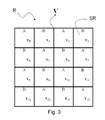
- a more robust, discriminative, scalable and compact image descriptor may be computed by transforming each of h 0 -h 15 of H and then performing scalar quantisation on the resultant transformed values. More specifically, each of h 0 -h 15 is transformed according to Transform A or Transform B, as shown below, according to the transform utilisation information of FIG.
- Transform A is applied to h 0 , h 2 , h 5 , h 7 , h 8 , h 10 , h 13 , h 15 and Transform B is applied to h 1 , h 3 , h 4 , h 6 , h 9 , h 11 , h 12 , h 14 , giving the transformed descriptor V with subdescriptors v 0 -v 15 , corresponding to h 0 -h 15 respectively, and each comprising elements v 0 -v 7 , giving a total of 128 elements.
- each element undergoes coarse scalar quantisation, for example ternary (3-level) quantisation, with the quantisation thresholds selected so as to achieve a specific occurrence probability distribution among the quantisation bins for each element.
- This scalar quantisation produces the quantised descriptor V, ⁇ tilde over ( ) ⁇ with subdescriptors v, ⁇ tilde over ( ) ⁇ 0 -v, ⁇ tilde over ( ) ⁇ 15 , each comprising elements v, ⁇ tilde over ( ) ⁇ 0 -v, ⁇ tilde over ( ) ⁇ 7 , again with a total of 128 elements.
- This compact descriptor captures the most discriminative and robust information contained in the original histograms of gradients, in the form of the shape of the distributions and the relationship among their bin values.
- descriptor V as well as its quantised version V, ⁇ tilde over ( ) ⁇ , is that it is highly scalable, and its dimensionality may be easily reduced if required by an application's storage requirements or a transmission channel's characteristics by simply eliminating one or more of its elements.
- descriptor V as well as its quantised version V, ⁇ tilde over ( ) ⁇ , is highly scalable, and its dimensionality may be easily reduced if required by an application's storage requirements or a transmission channel's characteristics by simply eliminating one or more of its elements.
- subdescriptors v 0 -v 15 each comprising elements v 0 -v 7 and, unless otherwise stated, it should be understood that the encoding of the quantised descriptor V, ⁇ tilde over ( ) ⁇ proceeds in a similar manner.
- FIGS. 4 a -4 e show exemplary sets of elements which have been found to produce excellent discriminative power and robustness for five target descriptor lengths, from descriptor length 0 (DL0), the shortest descriptor length utilising only 20 descriptor elements, to descriptor length 4 (DL4), the longest descriptor length utilising all 128 elements. More specifically, FIG. 4 a shows an exemplary set of elements for descriptor length DL0 comprising 20 elements, FIG. 4 b shows an exemplary set of elements for descriptor length DL1 comprising 40 elements, FIG. 4 c shows an exemplary set of elements for descriptor length DL2 comprising 64 elements, FIG.
- FIG. 4 d shows an exemplary set of elements for descriptor length DL3 comprising 80 elements
- FIG. 4 e shows an exemplary set of elements for descriptor length DL4 comprising all 128 elements.
- each element of each subdescriptor will or will not be encoded according to the element utilisation sets of FIG. 4 a - 4 e.
- the set of utilised elements for each descriptor length must be the same as or a subset of the set of utilised elements for all higher descriptor lengths, as illustrated in FIGS. 4 a -4 e .
- This allows the transcoding and comparison of descriptors of different lengths by simple elimination of the excess elements of the descriptor with the higher descriptor length so that it is reduced to the same set of elements as the descriptor with the lower descriptor length.
- a straightforward encoding method of this descriptor comprises calculating and encoding the elements in a “by-subdescriptor” order, i.e., in the general case as v 0,0 , v 0,1 , . . . , v 0,7 , v 1,0 , v 1,1 , . . . , v 1,7 , . . . , v 15,0 , v 15,1 , . . . , v 15,7 where v i,j denotes element v j of subdescriptor v i .
- v 7 for transformed histogram v 0 then encoding elements v 0 , v 1 , . . . , v 7 for transformed histogram v 1 , etc., using the appropriate transforms, for example as illustrated in FIG. 3 , and also using the appropriate element utilisation sets for the desired descriptor length, for example as illustrated in FIG. 4 , to decide which elements should be encoded.
- This encoding results, for example for a descriptor length DL0, to a descriptor v 0,0 , v 1,0 , v 2,0 , v 3,0 , v 4,0 , v 5,0 , v 5,6 , v 6,0 , v 6,6 , v 7,0 , v 8,0 , v 9,0 , v 9,6 , v 10,0 , v 10,6 , v 11,0 , v 12,0 , v 13,0 , v 14,0 , v 15,0 and for a descriptor length DL1 to a descriptor v 0,0 , v 0,1 , v 1,0 , v 1,1 , v 2,0 , v 2,1 , v 3,0 , v 3,1 , v 4,0 , v 4,1 , v 5,0 , v 5,1 , v 5,2 , v 5,6 , v 6,0 , v 6,1
- FIG. 5 illustrates the operation of such a straightforward encoder as a sequence of steps.
- a sequence of steps corresponds to steps which are conceptual and do not correspond to specific hardware of software implementations, components and instructions, but are representative of the overall operation of the encoder.
- FIG. 5 illustrates the operation of an encoder for a descriptor length DLk, for example corresponding to one of the descriptor lengths illustrated in FIG. 4 .
- the encoding of the descriptor begins at the first subdescriptor, i.e., v 0 .
- step S 110 the appropriate transform is selected for the subdescriptor being processed, for example according to the transform utilisation of FIG. 3 .
- the computation of descriptor V from descriptor H according to two different transforms as described here is only an example.
- the computation of descriptor V from descriptor H may also be performed according to a single transform, for example only Transform A or only Transform B, rendering step S 110 unnecessary, or according to more than two transforms.
- step S 120 the encoding of the subdescriptor being processed begins at the first subdescriptor element, i.e., v 0 .
- step S 130 the use or not of the particular element of the particular subdescriptor, i.e., v 0,0 is checked against the element utilisation information for descriptor length DLk, for example using one of the utilisation sets of FIG. 4 . If the element is not in use, then processing moves to step S 150 . If the element is in use for the descriptor length DLk, then its encoding takes place in step S 140 .
- the word “encoding” means one or more actions, or combination thereof, that make the element v 0,0 part of the local image descriptor, said actions including, but way of example and without limitation, the calculation according to the appropriate transform function of (1) or (2) seen earlier, the selection of the element for inclusion into the local image descriptor in the case all elements are pre-calculated without knowledge of which elements will be finally used in the descriptor, the quantisation of the element value, the storage of the element in volatile or non-volatile memory and the transmission of the element along a transmission channel.
- step S 150 if the current element is not the last element of the subdescriptor, the processing moves to the next element of the subdescriptor, otherwise the processing moves to step S 160 .
- step S 160 if the current subdescriptor is not the last subdescriptor of the local image descriptor, the processing moves to the next subdescriptor of the local image descriptor, otherwise the processing ends.
- Another straightforward encoding method of this descriptor comprises calculating and encoding the elements in a “by-element” order, i.e., in the general case as v 0,0 , v 1,0 , . . . , v 15,0 , v 0,1 , v 1,1 , . . . , v 15,1 , . . . , v 0,7 , v 1,7 , . . . , v 15,7 i.e. encoding element v 0 for subdescriptors v 0 , v 1 , . . .
- the decoder For the purposes of transcoding, decoding and processing, the decoder must also know the encoding process and the element ordering and utilisation sets to be able to process and compare descriptors, possibly of different lengths, for the purposes of the related computer vision applications.
- the element utilisation sets must be either permanently fixed or stored/transmitted alongside the descriptors. In this context, the straightforward encoding process is disadvantageous.
- the encoding is carried out according to subdescriptor groups, formed according to the redundancy patterns in the relative importance between the corresponding elements of said subdescriptor groups.
- said grouping is performed by grouping subdescriptors whose corresponding elements have a similar importance in an ordering of all the elements of the descriptor according to their relative importance in terms of achieving high recognition performance, more specifically by grouping subdescriptors according to their distance from the descriptor centre and additionally by grouping subdescriptors according to the distance between them and/or additionally by ordering the subdescriptors of a group according to corresponding encoding characteristics and/or additionally by ordering the subdescriptors of a group according to the distance between them.
- the encoding method according to the invention is advantageously more efficient that the prior art ones in terms of efficiency, of computational complexity and/or of the amount of information needed to generate scalable bitstreams.
- FIGS. 1 a and 1 b show an example of a prior art keypoint descriptor
- FIGS. 2 a and 2 b show histograms of gradients of the keypoint descriptor of FIG. 1 and bin values related to one of said histogram of gradients, respectively;
- FIG. 3 shows exemplary transforms to be applied to the histograms of gradients of FIG. 2 ;
- FIGS. 4 a -4 e show exemplary sets of elements for five respective targets descriptor lengths
- FIG. 5 represents a flow-chart illustrating the operation of an encoder using the sets of elements of FIG. 4 ;
- FIG. 6 shows an element utilisation order used by a method according to the present invention
- FIG. 7 illustrates the operation of an encoder using the element utilisation order of FIG. 6 ;
- FIG. 8 shows the centres of a region and of a subregion of a local image descriptor
- FIG. 9 shows a first grouping of subdescriptors of a local image descriptor according to a first embodiment or a fourth embodiment of a method according to the invention.
- FIGS. 12 and 14 show second and third exemplary groupings, respectively, of subdescriptors of a local image descriptor according to the first embodiment of a method according to the invention
- FIGS. 10, 13 and 15 show first, second and third group-element utilisation orders relating to the groupings of FIGS. 9, 12, 14 and 17 , respectively;
- FIG. 11 illustrates the operation of an encoder according to a first, second or fourth embodiment of a method according to the invention
- FIG. 16 shows a fourth exemplary grouping according to a first embodiment of a method according to the invention.
- FIG. 17 shows a fifth exemplary grouping of subdescriptors of a local image descriptor according to the second and third embodiment of a method according to the invention.
- FIG. 18 illustrates the operation of an encoder using the element utilisation order of FIG. 17 , according to third embodiment of a method according to the invention
- FIG. 19 illustrates the operation of an encoder according to a fourth embodiment of a method according to the invention.
- FIG. 20 shows an exemplary grouping of subdescriptors of a local image descriptor according to a fifth embodiment of a method according to the invention
- FIGS. 21 a -21 e show exemplary sets of elements according to the grouping of FIG. 20 ;
- FIGS. 22 a -22 e show the sets of elements of FIGS. 21 a -21 e , respectively, when converted into group-element utilisation sets;
- FIG. 23 illustrates the operation of an encoder for the encoding of a descriptor for providing the converted sets of elements of FIGS. 22 a - 22 e;
- FIG. 24 illustrates an image processing device suitable for carrying out the method according to the present invention.
- a more efficient encoder may operate according to an element utilisation order, producing a descriptor whose elements are ordered according to the element utilisation order and which can be converted to lower descriptor lengths by simple descriptor truncation.
- Such an element utilisation order may take the form of a 128-element ordered list, which may be encoded in 112 bytes, each list entry specifying a subdescriptor index and an element index, as illustrated in FIG. 6 . So, for example, FIG. 6 shows an element priority list whereby element v 5,0 is given the highest priority, element v 9,0 is given the second highest priority, etc. Therefore, such an element utilisation order encoder may produce a descriptor of length l by encoding the top l elements in the list.
- FIG. 7 illustrates the operation of such an encoder using the element utilisation order of FIG. 6 .
- the encoding of the descriptor begins with the element with the top priority (Priority 1) in the element utilisation order, i.e., element v 0 of subdescriptor v 5 .
- the appropriate transform is selected according to the subdescriptor to which this element belongs, for example according to the transform utilisation of FIG. 3 . It should be noted that the computation of descriptor V from descriptor H according to two different transforms as described here is only an example.
- the computation of descriptor V from descriptor H may also be performed according to a single transform, for example only Transform A or only Transform B, rendering step S 200 unnecessary, or according to more than two transforms.
- the encoding of the element i.e., v 5,0 , takes place in step S 210 .
- step S 220 if a desired number of l elements of the descriptor has not yet been encoded, the processing moves to the element with the next highest priority in the element utilisation order, otherwise the processing ends.
- step S 220 relates to the control of how many elements to encode, while steps S 200 and S 210 relate to the actual encoding of the local image descriptor.
- the encoder of FIG. 7 using an element utilisation order as in FIG. 6 , produces descriptors whose elements are ordered according to the element utilisation order and which can be converted to lower descriptor lengths by simple descriptor truncation, i.e., eliminating the last elements of the descriptor, and is more flexible than the encoder of FIG. 5 which uses element utilisation sets as in FIG. 4 .
- the number of elements l in the descriptor may be stored/transmitted alongside the descriptor, possibly at the image level.
- the decoder must also know the element ordering to be able to process for the purposes of the related computer vision applications.
- the element utilisation order must be either permanently fixed or stored/transmitted alongside the descriptors.
- V do not correspond to a single descriptor whose elements may be ordered according to a single priority list, but to 16 different 8-element subdescriptors, each subdescriptor extracted from a different histogram of gradients according to a specific transform and so that corresponding elements between all subdescriptors capture the relation between bins with the same angular separation.
- a descriptor needs to strike a balance between a uniform element distribution, i.e., selecting element(s) from as many subdescriptors as possible, and distance from the descriptor centre, i.e., giving higher priority to subdescriptors which are closer to the descriptor centre.
- a uniform element distribution i.e., selecting element(s) from as many subdescriptors as possible
- distance from the descriptor centre i.e., giving higher priority to subdescriptors which are closer to the descriptor centre.
- the importance of corresponding elements from different subdescriptors is approximately the same when the distance of the subdescriptors to the descriptor centre is the same, while the importance of corresponding elements from different subdescriptors increases as the distance of the subdescriptors to the descriptor centre decreases.
- the distance of a subdescriptor v to the descriptor centre refers to the distance between the centre of the subregion which corresponds to the histogram of gradients h which gives rise to the subdescriptor v and the centre of the region which comprises the subregions, as illustrated in FIG. 8 . While it is possible to refer back to the dimensions of the image region and subregions to compute said distances, it is not necessary since there is only interest in comparing said distances. Therefore said distances may be computed by assuming that each side of each subregion has, for example, a unit length.
- said distances are Euclidean distances, although other suitable distance measures may also be used.
- the subdescriptors are grouped according to their distance from the descriptor centre.
- the subdescriptors are ordered in ascending subdescriptor index order, although this is not restrictive and other orders may be used, such as clockwise starting from the top-most left-most subdescriptor in the group.
- the corresponding elements of the subdescriptors of the group are all assigned the same encoding priority.
- a group-element utilisation order may be generated, which may take the form of a 24-element ordered list, which may be encoded in 15 bytes, each list entry specifying a subdescriptor group and an element index, as illustrated in FIG. 10 .
- the group-element utilisation order of FIG. 10 is merely an example, and different group-element utilisation orders may be generated by changing the priorities of the entries in the list.
- FIG. 10 shows a group-element priority list whereby element v 0 of group g 2 is given the highest priority, instructing the encoder that the first four elements to encode are v 5,0 , v 6,0 , v 9,0 and v 10,0 , element v 0 of group g 1 is given the second highest priority, instructing the encoder that the next eight elements to encode are v 1,0 , v 2,0 , v 4,0 , v 7,0 , v 8,0 , v 11,0 , v 13,0 and v 14,0 , etc.
- FIG. 11 illustrates the operation of such an encoder using the group-element utilisation order of FIG. 10 and configured to encode the top m groups of elements in said group-element utilisation order.
- the encoding of the descriptor begins with the group of elements with the top priority (Priority 1) in the group-element utilisation order, i.e., element v 0 of group g 2 comprising subdescriptors v 5 , v 6 , v 9 , and v 10 .
- the encoding of the descriptor begins at the first subdescriptor of the group, i.e., v 5 .
- step S 310 the appropriate transform is selected for the subdescriptor, for example according to the transform utilisation of FIG. 3 .
- the computation of descriptor V from descriptor H according to two different transforms as described here is only an example.
- the computation of descriptor V from descriptor H may also be performed according to a single transform, for example only Transform A or only Transform B, rendering step S 310 unnecessary, or according to more than two transforms.
- the encoding of the element i.e., v 5,0 , takes place in step S 320 .
- step S 330 if the current subdescriptor is not the last subdescriptor in the group, the processing moves to the next subdescriptor, otherwise the processing moves to step S 340 . Then, in step S 340 , if the desired number of m groups of elements has not yet been encoded, the processing moves to the group of elements with the next highest priority in the group-element utilisation order, otherwise the processing ends.
- steps S 300 , S 330 and S 340 relate to the order in which the processing is performed and to the control of how many groups of elements to encode, while steps S 310 and S 320 relate to the actual encoding of the local image descriptor.
- the number of groups m or corresponding number of elements l in the descriptor may be stored/transmitted alongside the descriptor, possibly at the image level.
- the decoder must also know the encoding process and the element utilisation order to be able to process and compare descriptors for the purposes of the related computer vision applications, which means that the element utilisation order must be either fixed or transmitted alongside the descriptors.
- the element utilisation order may need to change the element utilisation order, possibly at the image or sub-image level, for example by giving higher priority to the subdescriptors closest to the descriptor centre, or by giving higher priority to a specific class of element, e.g., v 7 as opposed to v 2 , in order to achieve high recognition performance with a limited set of elements.
- the element utilisation order must be stored or transmitted alongside the descriptors.
- the group-element utilisation order of FIG. 10 represents a much lower overhead than the element utilisation order of FIG. 6 .
- subdescriptor grouping may be fixed and known to both the encoder and the decoder, or may be transmitted alongside the descriptors.
- the number of groups and the size of composition of each group may be encoded in less than 10 bytes.
- group g 0 contains subdescriptors of varying distances to the descriptor centre, but always further away from the centre than the subdescriptors of group g 0 .
- the corresponding elements of the subdescriptors of the group are all assigned the same encoding priority.
- a group-element utilisation order may be generated, which may take the form of a 16-element ordered list, which may be encoded in 8 bytes, each list entry specifying a subdescriptor group and an element index, as illustrated in FIG. 13 .
- the encoder of FIG. 11 may then be used again to encode a descriptor according to the group-element utilisation order of FIG. 13 .
- the group-element utilisation order of FIG. 13 is merely an example, and different group-element utilisation orders may be generated by changing the priorities of the entries in the list.
- the subdescriptors of groups g 1 and g 2 are the same distance from the centre of the descriptor.
- This grouping is obtained from the grouping of FIG. 9 by subdividing original group g 1 into new groups g 1 and g 2 .
- the advantage of this is that it results in groups with the same number of subdescriptors, which is desirable in optimised encoder implementations.
- a group-element utilisation order may be generated, which may take the form of a 32-element ordered list, which may be encoded in 20 bytes, each list entry specifying a subdescriptor group and an element index, as illustrated in FIG. 15 .
- the encoder of FIG. 11 may then be used again to encode a descriptor according to the group-element utilisation order of FIG. 15 .
- the group-element utilisation order of FIG. 15 is merely an example, and different group-element utilisation orders may be generated by changing the priorities of the entries in the list.
- groups g 0 and g 3 are identical to those of FIG. 14 , but the subdescriptors of g 1 and g 2 have been swapped compared to FIG. 14 so that each of those two groups contains one subdescriptor from the upper-left, upper-right, lower-left and lower-right part of the subdescriptor grid.
- the encoder of FIG. 7 differs from the encoder of FIG. 11 in that, unlike the former which produces descriptors of any length, the latter allow encoding of descriptors whose length has a granularity decided by the subdescriptor groups. In practice, the latter may be configured to produce descriptors of any length, as will be demonstrated later.
- the subdescriptors are grouped firstly according to their distance from the centre (first condition) and secondly according their reciprocal distances (second condition).
- the distance between subdescriptors may again take the form of a Euclidean distance or another suitable distance measures, such as Manhattan distance.
- the second condition may be, for example, that a group should not contain subdescriptors whose distance to each other is below a predetermined threshold.
- the predetermined threshold may be set to prevent, for example, grouping neighbouring subdescriptors.
- the aim of the secondary condition is to ensure that the subdescriptors of different groups are, whenever possible, drawn from relatively distant positions of the subdescriptor grid, thereby increasing the information content of descriptors of very low numbers of features. It should be noted that the secondary condition may not always be satisfied, e.g., it is not possible to satisfy it for a group which contains all the central subdescriptors v 5 , v 6 , v 9 , and v 10 .
- the subdescriptors of groups g 0 , g 1 and g 2 satisfy the condition that they contain no neighbouring subdescriptors.
- the corresponding elements of the subdescriptors of the group are all assigned the same encoding priority.
- a group-element utilisation order such as the one illustrated in FIG. 15 may be generated, and an encoder such as the one illustrated in FIG. 11 may then be used again to encode a descriptor according to the group-element utilisation order of FIG. 15 .
- the subdescriptors are grouped according to their distance from the centre and the subdescriptors of each group are encoded in a sequence defined according to their corresponding encoding characteristics, such as their corresponding transforms.
- the transform utilisation sequence must be “A A B B”, i.e., an encoding sequence whereby, for each subdescriptor group, the transform of the first subdescriptor in the group is transform A, the transform of the second subdescriptor in the group is also transform A, the transform of the third subdescriptor in the group is transform B, and the transform of the fourth subdescriptor in the group is also transform B.
- g 0 ⁇ v 0 , v 15 , v 3 , v 12 ⁇ , containing the subdescriptors with the greatest distance to the descriptor centre
- g 1 ⁇ v 7 , v 8 , v 1 , v 14 ⁇
- g 2 ⁇ v 2 , v 13 , v 4 , v 11 ⁇
- g 3 ⁇ v 5 , v 10 , v 6 , v 9 ⁇ , containing the subdescriptors with the smallest distance to the descriptor centre.
- the corresponding elements of the subdescriptors of the group are all assigned the same encoding priority. Furthermore, within each group, the transform utilisation information for the four subdescriptors in the group is always “A A B B”, which means than an efficient encoder implementation does not need to identify the applicable transform of each subdescriptor.
- FIG. 18 illustrates the operation of such an encoder using the group-element utilisation order of FIG. 15 and configured to encode the top m groups of elements in said group-element utilisation order.
- the encoding of the descriptor begins with the group of elements with the top priority (Priority 1) in the group-element utilisation order, i.e., element v 0 of group g 3 comprising subdescriptors v 5 , v 10 , v 6 , and v 9 .
- the encoding of the descriptor begins at the first subdescriptor of the group, i.e., v 5 .
- step S 410 Given that all groups have a common and fixed transform utilisation order, processing moves to step S 410 where the encoding of the element, i.e., v 5,0 , takes place.
- step S 420 if the current subdescriptor is not the last subdescriptor in the group, the processing moves to the next subdescriptor, otherwise the processing moves to step S 430 .
- step S 430 if the desired number of m groups of elements has not yet been encoded, the processing moves to the group of elements with the next highest priority in the group-element utilisation order, otherwise the processing ends.
- steps S 400 , S 420 and S 430 relate to the order in which the processing is performed and to the control of how many groups of elements to encode, while only step S 410 relates to the actual encoding of the local image descriptor.
- the common encoding sequence condition is defined on the transforms which are utilised within each group, but this condition may also be defined on other encoding characteristics, such as the type and level of quantisation, or combinations thereof.
- different encoding sequence conditions may be applied to different groups of subdescriptors.
- the grouping according to FIG. 9 results in three groups, namely g 0 , containing the four subdescriptors with the greatest distance to the descriptor centre, g 1 , containing the eight subdescriptors with the second greatest distance to the descriptor centre, and g 2 , containing the four subdescriptors with the smallest distance to the descriptor centre.
- an encoding sequence condition that the transform utilisation sequence must be “A A B B” may be applied to groups g 0 and g 2
- a different encoding sequence condition that the transform utilisation sequence must be “A A A A B B B B” may be applied to group g 1 .
- the subdescriptors are grouped according to their distance from the centre and the subdescriptors of each group are ordered according to their distances between them.
- the ordering condition may be, for example, that the distance between consecutive subdescriptors within a group should not be below a predetermined threshold.
- the predetermined threshold may be set to prevent, for example, consecutive neighbouring subdescriptors within a group.
- a different ordering condition may be, for example, that the distance between consecutive subdescriptors within a group is maximised.
- This ordering is particularly useful when employing large subdescriptor groups, to reduce the size of the group-element utilisation order, and partial group encoding, as explained below. It should be noted that this type of ordering may not always be possible, e.g., it is not possible to not have consecutive neighbouring descriptors for a group which contains all the central subdescriptors v 5 , v 6 , v 9 , and v 10 .
- the corresponding elements of the subdescriptors of the group are all assigned the same encoding priority.
- a group-element utilisation order such as the one illustrated in FIG. 10 may be generated, and an encoder such as the one illustrated in FIG. 11 may then be used again to encode a descriptor according to the group-element utilisation order of FIG. 10 .
- an encoder such as the one illustrated in FIG. 19 may be employed.
- FIG. 19 shows such a modification of the encoder of FIG. 11 .
- the encoder of FIG. 19 is obtained by simply swapping steps S 330 and S 340 of the encoder of FIG. 11 , allowing the encoder of FIG. 19 to terminate the encoding of a group as soon as the desired number of elements has been encoded.
- an analogous modification is also applicable to the encoder of FIG. 18 .
- the ordering of the subdescriptors within a group according to the distances between them is highly advantageous since it results in consecutive elements being drawn from relatively distant positions of the subdescriptor grid which, in the event of the partial encoding of a group, increases the information content of descriptors with a low number of features.
- the previous embodiments of the invention demonstrate efficient encoding of image descriptors according to a group-element utilisation order resulting from the grouping of subdescriptors into subdescriptor groups based on their distances from the descriptor centre and/or their distances to each other.
- subdescriptors may be grouped so that each subdescriptor within a group has an identical element utilisation set to all the other subdescriptors within a group.
- the group-element utilisation sets of FIG. 21 a -21 e may be converted into incremental group-element utilisation sets as illustrated in FIG. 22 a -22 e where, for each descriptor length (for example DL2 of FIG. 22 c ), the corresponding element utilisation set shows only the additional elements which make up the descriptor of said descriptor length compared to the immediately lower descriptor length (for example DL1 of FIG. 22 b ).
- an encoder may generate descriptors which can be converted to lower descriptor lengths by simple descriptor truncation.
- FIG. 23 illustrates the operation of such an encoder for the encoding of a descriptor of length DLk. More specifically, in step S 600 , the processing begins by encoding a descriptor of the lowest descriptor length, i.e., DL0. In step S 610 , the encoding of the DL0 descriptor begins with the encoding of the first subdescriptor group, i.e., g 0 , and in step S 620 the encoding of the first subdescriptor group begins with the encoding of the first element, i.e., v 0 .
- step S 630 if element v 0 is not in use for g 0 at descriptor length DL0 according to the incremental group-element utilisation sets of FIG. 22 , the processing moves to step S 680 , otherwise the processing moves to step S 640 .
- step S 640 the first subdescriptor of group g 0 is selected, i.e., v 5 , and in step S 650 the appropriate transform function is selected, for example according to FIG. 3 . It should be noted that the computation of descriptor V from descriptor H according to two different transforms as described here is only an example.
- the computation of descriptor V from descriptor H may also be performed according to a single transform, for example only Transform A or only Transform B, rendering step S 650 unnecessary, or according to more than two transforms.
- Step 660 the encoding of element v 5,0 takes place.
- step S 670 if the current subdescriptor is not the last subdescriptor in the group, the processing moves to the next subdescriptor in the group, otherwise the processing moves to step S 680 .
- step S 680 if the current element is not the last element, i.e., v 7 , the processing moves to the next element, otherwise the processing moves to step S 690 .
- step S 690 if the current subdescriptor group is not the last subdescriptor group, the processing moves to the next subdescriptor group, otherwise the processing moves to step S 695 .
- step S 695 if the current subdescriptor length is not the target subdescriptor length, the processing moves to the next subdescriptor length, encoding the additional elements specified by the incremental group-element utilisation sets. Otherwise, the processing ends.
- FIG. 24 illustrates a conceptual image processing apparatus for carrying out the method according to the present invention. More specifically, processing apparatus 1100 receives input, which may comprise visual data, such as image or video data, pre-calculated descriptors based on histograms of gradients, pre-calculated compact descriptors according to the method of the present invention, programming instructions, or user input, from input apparatus 1000 , which may take the form of a user input apparatus, a media reader, or a receiver of transmitted signals.
- input apparatus 1000 may take the form of a user input apparatus, a media reader, or a receiver of transmitted signals.
- the processing apparatus 1100 comprises the main processing blocks of a central processing unit 1110 which controls the operations of the other processing blocks, volatile memory 1120 , non-volatile memory 1130 , optionally a descriptor extractor block 1140 configured to generate descriptors based on histograms of gradients, a compact descriptor encoder block 1150 configured to carry out the method according to the present invention, and optionally a compact descriptor processor block 1160 configured to process said compact descriptors, for example to establish or verify visual correspondences.
- Processing apparatus 1100 is connected to output apparatus 1900 , which may take the form of a visual display unit, a media writer, or a transmitter of signals, which provides output which may comprise annotated visual data, such as image or video data, processing information such as established or verified visual correspondences, or compact descriptors according to the method of the present invention. It should be understood that the processing blocks and architecture shown in FIG. 24 are only conceptual and may not correspond exactly to every apparatus implementing the method according to the invention.
- the present invention is not limited to a method for encoding an image descriptor based on a gradient histogram and a relative image processing apparatus, but may be subject to many modifications, improvements or replacements of equivalent parts and elements without departing from the inventive idea, as clearly specified in the following claims.
Landscapes
- Engineering & Computer Science (AREA)
- Multimedia (AREA)
- Signal Processing (AREA)
- Physics & Mathematics (AREA)
- General Physics & Mathematics (AREA)
- Theoretical Computer Science (AREA)
- Compression Or Coding Systems Of Tv Signals (AREA)
- Image Analysis (AREA)
- Compression Of Band Width Or Redundancy In Fax (AREA)
- Image Processing (AREA)
- Facsimile Image Signal Circuits (AREA)
- Editing Of Facsimile Originals (AREA)
- Compression, Expansion, Code Conversion, And Decoders (AREA)
- Information Retrieval, Db Structures And Fs Structures Therefor (AREA)
Applications Claiming Priority (4)
| Application Number | Priority Date | Filing Date | Title |
|---|---|---|---|
| ITTO2013A0629 | 2013-07-24 | ||
| ITTO2013A000629 | 2013-07-24 | ||
| IT000629A ITTO20130629A1 (it) | 2013-07-24 | 2013-07-24 | Method for encoding an image descriptor based on a gradient histogram and relative image processing apparatus |
| PCT/IB2014/063158 WO2015011612A1 (en) | 2013-07-24 | 2014-07-16 | Image processing apparatus and method for encoding an image descriptor based on a gradient histogram |
Publications (2)
| Publication Number | Publication Date |
|---|---|
| US20160162749A1 US20160162749A1 (en) | 2016-06-09 |
| US9779320B2 true US9779320B2 (en) | 2017-10-03 |
Family
ID=49226413
Family Applications (1)
| Application Number | Title | Priority Date | Filing Date |
|---|---|---|---|
| US14/906,485 Active US9779320B2 (en) | 2013-07-24 | 2014-07-16 | Image processing apparatus and method for encoding an image descriptor based on a gradient histogram |
Country Status (16)
| Country | Link |
|---|---|
| US (1) | US9779320B2 (it) |
| EP (2) | EP3633547A1 (it) |
| JP (2) | JP6514200B2 (it) |
| KR (1) | KR102175697B1 (it) |
| CN (3) | CN110365979A (it) |
| AR (1) | AR097052A1 (it) |
| BR (1) | BR112016001479B1 (it) |
| DK (1) | DK3025274T3 (it) |
| ES (1) | ES2776196T3 (it) |
| HU (1) | HUE048315T2 (it) |
| IT (1) | ITTO20130629A1 (it) |
| PL (1) | PL3025274T3 (it) |
| PT (1) | PT3025274T (it) |
| RU (3) | RU2678668C2 (it) |
| TW (1) | TWI576770B (it) |
| WO (1) | WO2015011612A1 (it) |
Families Citing this family (4)
| Publication number | Priority date | Publication date | Assignee | Title |
|---|---|---|---|---|
| ITTO20130629A1 (it) * | 2013-07-24 | 2015-01-25 | Sisvel Technology Srl | Method for encoding an image descriptor based on a gradient histogram and relative image processing apparatus |
| US10360721B2 (en) | 2016-05-26 | 2019-07-23 | Mediatek Inc. | Method and apparatus for signaling region of interests |
| KR102466214B1 (ko) * | 2020-05-08 | 2022-11-10 | 한국기술교육대학교 산학협력단 | 부품의 3차원 모델 분류 방법, 이를 위한 컴퓨터 프로그램 및 장치 |
| CN111931794B (zh) * | 2020-09-16 | 2021-03-09 | 中山大学深圳研究院 | 一种基于草图的图像匹配方法 |
Citations (6)
| Publication number | Priority date | Publication date | Assignee | Title |
|---|---|---|---|---|
| US20090172730A1 (en) * | 2007-12-27 | 2009-07-02 | Jeremy Schiff | System and method for advertisement delivery optimization |
| US8054170B1 (en) * | 2008-09-30 | 2011-11-08 | Adobe Systems Incorporated | Characterizing and representing images |
| US20120127276A1 (en) | 2010-11-22 | 2012-05-24 | Chi-Hung Tsai | Image retrieval system and method and computer product thereof |
| US20130121587A1 (en) | 2010-08-26 | 2013-05-16 | Jonathan W. Brandt | Systems and methods for large scale, high-dimensional searches |
| US20130155063A1 (en) | 2011-12-20 | 2013-06-20 | Apple Inc. | Face Feature Vector Construction |
| US20140006385A1 (en) * | 2012-06-28 | 2014-01-02 | Bjoern-Ole Ebers | Image search refinement using facets |
Family Cites Families (12)
| Publication number | Priority date | Publication date | Assignee | Title |
|---|---|---|---|---|
| US6865295B2 (en) * | 2001-05-11 | 2005-03-08 | Koninklijke Philips Electronics N.V. | Palette-based histogram matching with recursive histogram vector generation |
| GB2418555A (en) * | 2004-09-23 | 2006-03-29 | Mitsubishi Electric Inf Tech | Representing an image using descriptors based on colour information |
| US20120265768A1 (en) * | 2008-10-08 | 2012-10-18 | Mitsubishi Electric Corporation | Encoding and decoding method and apparatus for multimedia signatures |
| WO2010055399A1 (en) * | 2008-11-12 | 2010-05-20 | Nokia Corporation | Method and apparatus for representing and identifying feature descriptors utilizing a compressed histogram of gradients |
| WO2011044497A2 (en) * | 2009-10-09 | 2011-04-14 | Edgenet, Inc. | Automatic method to generate product attributes based solely on product images |
| RU2427911C1 (ru) * | 2010-02-05 | 2011-08-27 | Фирма "С1 Ко., Лтд." | Способ обнаружения лиц на изображении с применением каскада классификаторов |
| HUE051391T2 (hu) * | 2010-04-13 | 2021-03-01 | Ge Video Compression Llc | Szignifikancia térképek és transzformációs együttható blokkok kódolása |
| CN101894261B (zh) * | 2010-06-29 | 2012-05-02 | 武汉大学 | 一种多对比度模式直方图纹理描述子提取方法 |
| JP6044547B2 (ja) * | 2011-11-18 | 2016-12-14 | 日本電気株式会社 | 局所特徴量抽出装置、局所特徴量抽出方法、及びプログラム |
| EP2801055B1 (en) * | 2012-01-02 | 2016-04-20 | Telecom Italia S.p.A. | Method and system for image analysis |
| ITTO20120602A1 (it) | 2012-07-09 | 2014-01-10 | Sisvel Technology Srl | Method for transforming an image descriptor based on a gradient histogram and relative image processing apparatus. |
| ITTO20130629A1 (it) * | 2013-07-24 | 2015-01-25 | Sisvel Technology Srl | Method for encoding an image descriptor based on a gradient histogram and relative image processing apparatus |
-
2013
- 2013-07-24 IT IT000629A patent/ITTO20130629A1/it unknown
-
2014
- 2014-07-14 TW TW103124152A patent/TWI576770B/zh not_active IP Right Cessation
- 2014-07-16 PT PT147777809T patent/PT3025274T/pt unknown
- 2014-07-16 ES ES14777780T patent/ES2776196T3/es active Active
- 2014-07-16 HU HUE14777780A patent/HUE048315T2/hu unknown
- 2014-07-16 KR KR1020167004414A patent/KR102175697B1/ko active IP Right Grant
- 2014-07-16 PL PL14777780T patent/PL3025274T3/pl unknown
- 2014-07-16 DK DK14777780.9T patent/DK3025274T3/da active
- 2014-07-16 EP EP19209983.6A patent/EP3633547A1/en not_active Withdrawn
- 2014-07-16 RU RU2016105699A patent/RU2678668C2/ru active
- 2014-07-16 WO PCT/IB2014/063158 patent/WO2015011612A1/en active Application Filing
- 2014-07-16 EP EP14777780.9A patent/EP3025274B1/en not_active Not-in-force
- 2014-07-16 CN CN201910738846.8A patent/CN110365979A/zh active Pending
- 2014-07-16 CN CN201910739034.5A patent/CN110298367A/zh active Pending
- 2014-07-16 JP JP2016528631A patent/JP6514200B2/ja not_active Expired - Fee Related
- 2014-07-16 CN CN201480041502.7A patent/CN105493106B/zh not_active Expired - Fee Related
- 2014-07-16 BR BR112016001479-0A patent/BR112016001479B1/pt active IP Right Grant
- 2014-07-16 RU RU2019101654A patent/RU2698765C2/ru active
- 2014-07-16 US US14/906,485 patent/US9779320B2/en active Active
- 2014-07-24 AR ARP140102759A patent/AR097052A1/es unknown
-
2019
- 2019-04-11 JP JP2019075614A patent/JP6745939B2/ja not_active Expired - Fee Related
- 2019-08-09 RU RU2019125322A patent/RU2019125322A/ru unknown
Patent Citations (8)
| Publication number | Priority date | Publication date | Assignee | Title |
|---|---|---|---|---|
| US20090172730A1 (en) * | 2007-12-27 | 2009-07-02 | Jeremy Schiff | System and method for advertisement delivery optimization |
| US8054170B1 (en) * | 2008-09-30 | 2011-11-08 | Adobe Systems Incorporated | Characterizing and representing images |
| US20130121587A1 (en) | 2010-08-26 | 2013-05-16 | Jonathan W. Brandt | Systems and methods for large scale, high-dimensional searches |
| US20120127276A1 (en) | 2010-11-22 | 2012-05-24 | Chi-Hung Tsai | Image retrieval system and method and computer product thereof |
| TW201222288A (en) | 2010-11-22 | 2012-06-01 | Inst Information Industry | Image retrieving system and method and computer program product thereof |
| US20130155063A1 (en) | 2011-12-20 | 2013-06-20 | Apple Inc. | Face Feature Vector Construction |
| TW201327478A (zh) | 2011-12-20 | 2013-07-01 | Apple Inc | 面部特徵向量之建構 |
| US20140006385A1 (en) * | 2012-06-28 | 2014-01-02 | Bjoern-Ole Ebers | Image search refinement using facets |
Non-Patent Citations (10)
| Title |
|---|
| B. S. MANJUNATH, JENS-RAINER OHM, VINOD V. VASUDEVAN, AKIO YAMADA: "Color and Texture Descriptors", IEEE TRANSACTIONS ON CIRCUITS AND SYSTEMS FOR VIDEO TECHNOLOGY, INSTITUTE OF ELECTRICAL AND ELECTRONICS ENGINEERS, USA, vol. 11, no. 6, 1 June 2001 (2001-06-01), USA, XP011014212, ISSN: 1051-8215, DOI: 10.1109/76.927424 |
| B.S. Manjunath et al., Color and Texture Descriptors, IEEE Transactions on Circuits and Systems for Video Technology, vol. 11, No. 6, Jun. 2001, XP011014212, pp. 703-713. |
| International Search Report dated Dec. 10, 2014, issued in PCT Application No. PCT/IB2014/063158, filed Jul. 15, 2014. |
| MA R, CHEN J, SU Z: "MI-SIFT: Mirror and Inversion Invariant Generalization for SIFT Descriptor", CIVR, ACM, US, 5 July 2010 (2010-07-05) - 7 July 2010 (2010-07-07), US, pages 228 - 235, XP007918135, ISBN: 978-1-4503-0117-6 |
| Mehmet Firat Vural et al., Registration of Multispectral Satellite Images with Orientation-Restricted SIFT, Geoscience and Remote Sensing Symposium, 2009 IEEE International, XP03163120, Jul. 12, 2009, pp. 111-243. |
| Rui Ma et al., MI-SIFT: Mirror and Inversion Invariant Generalization for SIFT Descriptor, CIVR, ACM, Jul. 5, 2010, XP007918135, pp. 228-235. |
| V. CHANDRASEKHAR ; G. TAKACS ; D. CHEN ; S. TSAI ; R. GRZESZCZUK ; B. GIROD: "CHoG: Compressed histogram of gradients A low bit-rate feature descriptor", 2009 IEEE CONFERENCE ON COMPUTER VISION AND PATTERN RECOGNITION : CVPR 2009 ; MIAMI [BEACH], FLORIDA, USA, 20 - 25 JUNE 2009, IEEE, PISCATAWAY, NJ, 20 June 2009 (2009-06-20), Piscataway, NJ, pages 2504 - 2511, XP031607260, ISBN: 978-1-4244-3992-8 |
| VIJAY CHANDRASEKHAR , MINA MAKAR , GABRIEL TAKACS , DAVID CHEN , SAM S. TSAI , NGAI-MAN CHEUNG , RADEK GRZESZCZUK , YURIY REZNIK ,: "Survey of SIFT Compression schemes", STANFORD UNIVERSITY, pages 1 - 8, XP002719362, Retrieved from the Internet <URL:http://www.stanford.edu/~mamakar/pub_files/VijayICPR-WMMP2010.pdf> [retrieved on 20140128] |
| Vijay Chandrasekhar et al., ChoG: Compressed Histogram of Gradients A Low Bit-Rate Feature Descriptor, 2009 IEEE Conference on Computer Vision and Pattern Recognition, Jun. 20-25, 2009, XP031607260, pp. 2504-2511. |
| Vijay Chandrasekhar et al., Survey of SIFT Compression Schemes, Stanford University, Dec. 31, 2010, XP002719362, 8 pgs. |
Also Published As
Similar Documents
| Publication | Publication Date | Title |
|---|---|---|
| JP6745939B2 (ja) | 勾配ヒストグラムに基づいて画像記述子を符号化する方法および関連する画像処理装置 | |
| Jégou et al. | Searching in one billion vectors: re-rank with source coding | |
| Özkan et al. | Performance analysis of state-of-the-art representation methods for geographical image retrieval and categorization | |
| US10713523B2 (en) | Method for transforming an image descriptor based on a gradient histogram and relative image processing apparatus | |
| CN102098508B (zh) | 多媒体签名的编码和解码 | |
| US9747308B2 (en) | Method and apparatus for searching an image, and computer-readable recording medium for executing the method | |
| WO2016075274A1 (en) | Methods, systems and apparatus for image recognition based on recursively determined exemplar-support vector machines (e-svm) features | |
| Redondi et al. | Low bitrate coding schemes for local image descriptors | |
| Lin et al. | Learning multiple codebooks for low bit rate mobile visual search | |
| Tra et al. | Dominant SIFT: A novel compact descriptor | |
| JP6195365B2 (ja) | ベクトル符号化プログラム、装置及び方法 | |
| Jégou et al. | Searching with quantization: approximate nearest neighbor search using short codes and distance estimators | |
| Sandhawalia et al. | Searching with expectations | |
| CN116777727B (zh) | 存算一体芯片、图像处理方法、电子设备及存储介质 | |
| Uchida et al. | Ratio voting: A new voting strategy for large-scale image retrieval | |
| Reznik et al. | Fast quantization and matching of histogram-based image features | |
| Wang et al. | PQ-WGLOH: A bit-rate scalable local feature descriptor | |
| Noh et al. | Disentangled Representation Learning for Unsupervised Neural Quantization | |
| Ercoli et al. | Efficient and compact visual feature descriptors hashing using hierarchical multiple assignment k-means | |
| Yuan | Indexing, searching, and mining large-scale visual data via structured vector quantization | |
| Malaguti et al. | Low complexity SIFT compression techniques | |
| Schmid | Searching with quantization: approximate nearest neighbor search using short codes and distance estimators |
Legal Events
| Date | Code | Title | Description |
|---|---|---|---|
| AS | Assignment |
Owner name: SISVEL TECHNOLOGIES S.R.L., ITALY Free format text: ASSIGNMENT OF ASSIGNORS INTEREST;ASSIGNOR:PASCHALAKIS, STAVROS;REEL/FRAME:041250/0684 Effective date: 20160215 |
|
| AS | Assignment |
Owner name: SISVEL TECHNOLOGY S.R.L., ITALY Free format text: CORRECTIVE ASSIGNMENT TO CORRECT THE ASSIGNEE NAME PREVIOUSLY RECORDED AT REEL: 041250 FRAME: 0684. ASSIGNOR(S) HEREBY CONFIRMS THE ASSIGNMENT;ASSIGNOR:PASCHALAKIS, STAVROS;REEL/FRAME:043483/0941 Effective date: 20160215 |
|
| STCF | Information on status: patent grant |
Free format text: PATENTED CASE |
|
| AS | Assignment |
Owner name: NEW LUCK GLOBAL LIMITED, VIRGIN ISLANDS, BRITISH Free format text: ASSIGNMENT OF ASSIGNORS INTEREST;ASSIGNOR:SISVEL TECHNOLOGY S.R.L.;REEL/FRAME:047096/0211 Effective date: 20180911 |
|
| MAFP | Maintenance fee payment |
Free format text: PAYMENT OF MAINTENANCE FEE, 4TH YR, SMALL ENTITY (ORIGINAL EVENT CODE: M2551); ENTITY STATUS OF PATENT OWNER: SMALL ENTITY Year of fee payment: 4 |