EP3633547A1 - Image processing apparatus and method for encoding an image descriptor based on a gradient histogram - Google Patents
Image processing apparatus and method for encoding an image descriptor based on a gradient histogram Download PDFInfo
- Publication number
- EP3633547A1 EP3633547A1 EP19209983.6A EP19209983A EP3633547A1 EP 3633547 A1 EP3633547 A1 EP 3633547A1 EP 19209983 A EP19209983 A EP 19209983A EP 3633547 A1 EP3633547 A1 EP 3633547A1
- Authority
- EP
- European Patent Office
- Prior art keywords
- descriptor
- encoding
- subdescriptors
- group
- subdescriptor
- Prior art date
- Legal status (The legal status is an assumption and is not a legal conclusion. Google has not performed a legal analysis and makes no representation as to the accuracy of the status listed.)
- Withdrawn
Links
Images


Classifications
-
- G—PHYSICS
- G06—COMPUTING; CALCULATING OR COUNTING
- G06T—IMAGE DATA PROCESSING OR GENERATION, IN GENERAL
- G06T9/00—Image coding
-
- G—PHYSICS
- G06—COMPUTING; CALCULATING OR COUNTING
- G06V—IMAGE OR VIDEO RECOGNITION OR UNDERSTANDING
- G06V10/00—Arrangements for image or video recognition or understanding
- G06V10/20—Image preprocessing
- G06V10/28—Quantising the image, e.g. histogram thresholding for discrimination between background and foreground patterns
-
- G—PHYSICS
- G06—COMPUTING; CALCULATING OR COUNTING
- G06V—IMAGE OR VIDEO RECOGNITION OR UNDERSTANDING
- G06V10/00—Arrangements for image or video recognition or understanding
- G06V10/40—Extraction of image or video features
- G06V10/50—Extraction of image or video features by performing operations within image blocks; by using histograms, e.g. histogram of oriented gradients [HoG]; by summing image-intensity values; Projection analysis
-
- H—ELECTRICITY
- H04—ELECTRIC COMMUNICATION TECHNIQUE
- H04N—PICTORIAL COMMUNICATION, e.g. TELEVISION
- H04N19/00—Methods or arrangements for coding, decoding, compressing or decompressing digital video signals
- H04N19/10—Methods or arrangements for coding, decoding, compressing or decompressing digital video signals using adaptive coding
- H04N19/134—Methods or arrangements for coding, decoding, compressing or decompressing digital video signals using adaptive coding characterised by the element, parameter or criterion affecting or controlling the adaptive coding
- H04N19/136—Incoming video signal characteristics or properties
- H04N19/14—Coding unit complexity, e.g. amount of activity or edge presence estimation
-
- H—ELECTRICITY
- H04—ELECTRIC COMMUNICATION TECHNIQUE
- H04N—PICTORIAL COMMUNICATION, e.g. TELEVISION
- H04N19/00—Methods or arrangements for coding, decoding, compressing or decompressing digital video signals
- H04N19/90—Methods or arrangements for coding, decoding, compressing or decompressing digital video signals using coding techniques not provided for in groups H04N19/10-H04N19/85, e.g. fractals
-
- H—ELECTRICITY
- H04—ELECTRIC COMMUNICATION TECHNIQUE
- H04N—PICTORIAL COMMUNICATION, e.g. TELEVISION
- H04N19/00—Methods or arrangements for coding, decoding, compressing or decompressing digital video signals
- H04N19/30—Methods or arrangements for coding, decoding, compressing or decompressing digital video signals using hierarchical techniques, e.g. scalability
-
- H—ELECTRICITY
- H04—ELECTRIC COMMUNICATION TECHNIQUE
- H04N—PICTORIAL COMMUNICATION, e.g. TELEVISION
- H04N19/00—Methods or arrangements for coding, decoding, compressing or decompressing digital video signals
- H04N19/40—Methods or arrangements for coding, decoding, compressing or decompressing digital video signals using video transcoding, i.e. partial or full decoding of a coded input stream followed by re-encoding of the decoded output stream
Definitions
- the present invention relates to a method for efficiently encoding, transcoding, decoding and processing image descriptors computed in local regions around image interest keypoints and to an image processing device comprising means for encoding, transcoding, decoding and processing such descriptors.
- image descriptors have found wide applicability in many computer vision applications including object recognition, content-based image retrieval, and image registration, to name a few.
- local image descriptors are formed as follows: first, a search across multiple images scales and locations is performed to identify and localise stable image keypoints that are invariant to scale and orientation; then, for each keypoint, one or more dominant orientations are determined based on local image gradients, allowing the subsequent local descriptor computation to be performed relative to the assigned orientation, scale and location of each keypoint, thus achieving invariance to these transformations. Then, local image descriptors around keypoints are formed as follows: first, gradient magnitude and orientation information is calculated at image sample points in a region around the keypoint; then, these samples are accumulated into orientation histograms summarizing the contents over n ⁇ n subregions.
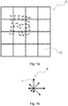
- FIG. 1a shows a subdivision of a local region R into 4 ⁇ 4 subregions SR and Figure 1b shows a subdivision of the 360° range of orientations into eight bins for each orientation histogram, with the length of each arrow corresponding to the magnitude of that histogram entry.
- a robust, discriminative, scalable and compact image descriptor may be calculated from a SIFT descriptor as follows.
- H in an entire SIFT descriptor comprising 16 histograms of gradients h each with eight bins h
- V is an entire local descriptor according to the present invention comprising 16 subdescriptors v each with eight elements v.
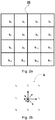
- H denote a SIFT local image descriptor comprising 16 histograms of gradients h 0 - h 15 , as shown in Figure 2a , each histogram comprising eight bin values h 0 - h 7 , as shown in Figure 2b .
- a more robust, discriminative, scalable and compact image descriptor may be computed by transforming each of h 0 - h 15 of H and then performing scalar quantisation on the resultant transformed values. More specifically, each of h 0 - h 15 is transformed according to Transform A or Transform B, as shown below, according to the transform utilisation information of Figure 3 , i.e.
- Transform A is applied to h 0 , h 2 , h 5 , h 7 , h 8 , h 10 , h 13 , h 15 and Transform B is applied to h 1 , h 3 , h 4 , h 6 , h 9 , h 11 , h 12 , h 14 , giving the transformed descriptor V with subdescriptors v 0 - v 15 , corresponding to h 0 - h 15 respectively, and each comprising elements v 0 -v 7 , giving a total of 128 elements.
- each element undergoes coarse scalar quantisation, for example ternary (3-level) quantisation, with the quantisation thresholds selected so as to achieve a specific occurrence probability distribution among the quantisation bins for each element.
- This scalar quantisation produces the quantised descriptor V , ⁇ with subdescriptors v , ⁇ 0 - v , ⁇ 15 , each comprising elements v, ⁇ 0 -v, ⁇ 7 , again with a total of 128 elements.
- This compact descriptor captures the most discriminative and robust information contained in the original histograms of gradients, in the form of the shape of the distributions and the relationship among their bin values.
- descriptor V as well as its quantised version V , ⁇ , is that it is highly scalable, and its dimensionality may be easily reduced if required by an application's storage requirements or a transmission channel's characteristics by simply eliminating one or more of its elements.
- descriptor V as well as its quantised version V , ⁇ , is highly scalable, and its dimensionality may be easily reduced if required by an application's storage requirements or a transmission channel's characteristics by simply eliminating one or more of its elements.
- subdescriptors v 0 - v 15 each comprising elements v 0 -v 7 and, unless otherwise stated, it should be understood that the encoding of the quantised descriptor V , ⁇ proceeds in a similar manner.
- Figures 4a-4e show exemplary sets of elements which have been found to produce excellent discriminative power and robustness for five target descriptor lengths, from descriptor length 0 (DL0), the shortest descriptor length utilising only 20 descriptor elements, to descriptor length 4 (DL4), the longest descriptor length utilising all 128 elements.
- Figure 4a shows an exemplary set of elements for descriptor length DL0 comprising 20 elements
- Figure 4b shows an exemplary set of elements for descriptor length DL1 comprising 40 elements
- Figure 4c shows an exemplary set of elements for descriptor length DL2 comprising 64 elements
- Figure 4d shows an exemplary set of elements for descriptor length DL3 comprising 80 elements
- Figure 4e shows an exemplary set of elements for descriptor length DL4 comprising all 128 elements.
- each element of each subdescriptor will or will not be encoded according to the element utilisation sets of Figure 4a-4e .
- a straightforward encoding method of this descriptor comprises calculating and encoding the elements in a "by-subdescriptor" order, i.e. in the general case as v 0,0, v 0,1, ..., v 0,7, v 1,0, v 1,1, ..., v 1,7 , ..., v 15,0 , v 15,1 , ..., v 15,7 where v i,j denotes element v j of subdescriptor v i .
- This encoding results, for example for a descriptor length DL0, to a descriptor v 0,0 , v 1,0 , v 2,0 , v 3,0 , v 4,0 , v 5,0 , v 5,6 , v 6,0 , v 6,6 , v 7,0 , v 8,0 , v 9,0 , v 9,6 , v 10,0 , v 10,6 , v 11,0 , v 12,0 , v 13,0 , v 14,0 , v 15,0 and for a descriptor length DL1 to a descriptor v 0,0 , v 0,1 , v 1,0 , v 1,1 , v 2,0 , v 2,1 , v 3,0 , v 3,1 , v 4,0 , v 4,1 , v 5,0 , v 5,1 , v 5,2 , v 5,6 , v 6,0 , v 6,1
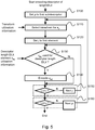
- Figure 5 illustrates the operation of such a straightforward encoder as a sequence of steps.
- a sequence of steps corresponds to steps which are conceptual and do not correspond to specific hardware of software implementations, components and instructions, but are representative of the overall operation of the encoder.
- Figure 5 illustrates the operation of an encoder for a descriptor length DL k , for example corresponding to one of the descriptor lengths illustrated in Figure 4 .
- the encoding of the descriptor begins at the first subdescriptor, i.e. v 0 .
- step S110 the appropriate transform is selected for the subdescriptor being processed, for example according to the transform utilisation of Figure 3 .
- the computation of descriptor V from descriptor H according to two different transforms as described here is only an example.
- the computation of descriptor V from descriptor H may also be performed according to a single transform, for example only Transform A or only Transform B, rendering step S110 unnecessary, or according to more than two transforms.
- step S120 the encoding of the subdescriptor being processed begins at the first subdescriptor element, i.e. v 0 .
- step S130 the use or not of the particular element of the particular subdescriptor, i.e.
- v 0,0 is checked against the element utilisation information for descriptor length DL k , for example using one of the utilisation sets of Figure 4 . If the element is not in use, then processing moves to step S150. If the element is in use for the descriptor length DL k , then its encoding takes place in step S140.
- the word "encoding” means one or more actions, or combination thereof, that make the element v 0,0 part of the local image descriptor, said actions including, but way of example and without limitation, the calculation according to the appropriate transform function of (1) or (2) seen earlier, the selection of the element for inclusion into the local image descriptor in the case all elements are pre-calculated without knowledge of which elements will be finally used in the descriptor, the quantisation of the element value, the storage of the element in volatile or non-volatile memory and the transmission of the element along a transmission channel.
- step S140 After step S140, or if it was decided that the element is not in use for the descriptor length DL k in step S130, the processing moves to step S150.
- step S150 if the current element is not the last element of the subdescriptor, the processing moves to the next element of the subdescriptor, otherwise the processing moves to step S160.
- step S160 if the current subdescriptor is not the last subdescriptor of the local image descriptor, the processing moves to the next subdescriptor of the local image descriptor, otherwise the processing ends.
- steps S100, S120, S150, and S160 relate to the order in which the processing is performed, while steps S110, S130 and S140 relate to the actual encoding of the local image descriptor.
- Another straightforward encoding method of this descriptor comprises calculating and encoding the elements in a "by-element" order, i.e. in the general case as v 0,0 v 1,0 , ..., v 15,0 , v 0,1 , v 1,1 , ..., v 15,1 , ..., v 0,7 , v 1,7 , ..., v 15,7 i.e.
- the decoder For the purposes of transcoding, decoding and processing, the decoder must also know the encoding process and the element ordering and utilisation sets to be able to process and compare descriptors, possibly of different lengths, for the purposes of the related computer vision applications.
- the element utilisation sets must be either permanently fixed or stored/transmitted alongside the descriptors. In this context, the straightforward encoding process is disadvantageous.
- a method for efficiently encoding image descriptors such as the ones above described by encoding them according to an element utilisation order, resulting in scalable descriptors which can be converted to lower descriptor lengths by simple descriptor truncation instead of parsing.
- the encoding is carried out according to subdescriptor groups, formed according to the redundancy patterns in the relative importance between the corresponding elements of said subdescriptor groups.
- said grouping is performed by grouping subdescriptors whose corresponding elements have a similar importance in an ordering of all the elements of the descriptor according to their relative importance in terms of achieving high recognition performance, more specifically by grouping subdescriptors according to their distance from the descriptor centre and additionally by grouping subdescriptors according to the distance between them and/or additionally by ordering the subdescriptors of a group according to corresponding encoding characteristics and/or additionally by ordering the subdescriptors of a group according to the distance between them.
- the encoding method according to the invention is advantageously more efficient that the prior art ones in terms of efficiency, of computational complexity and/or of the amount of information needed to generate scalable bitstreams.
- a more efficient encoder may operate according to an element utilisation order, producing a descriptor whose elements are ordered according to the element utilisation order and which can be converted to lower descriptor lengths by simple descriptor truncation.
- Such an element utilisation order may take the form of a 128-element ordered list, which may be encoded in 112 bytes, each list entry specifying a subdescriptor index and an element index, as illustrated in Figure 6 . So, for example, Figure 6 shows an element priority list whereby element v 5,0 is given the highest priority, element v 9,0 is given the second highest priority, etc. Therefore, such an element utilisation order encoder may produce a descriptor of length l by encoding the top l elements in the list.
- Figure 7 illustrates the operation of such an encoder using the element utilisation order of Figure 6 .
- the encoding of the descriptor begins with the element with the top priority (Priority 1) in the element utilisation order, i.e. element v 0 of subdescriptor v 5 .
- the appropriate transform is selected according to the subdescriptor to which this element belongs, for example according to the transform utilisation of Figure 3 . It should be noted that the computation of descriptor V from descriptor H according to two different transforms as described here is only an example.
- the computation of descriptor V from descriptor H may also be performed according to a single transform, for example only Transform A or only Transform B, rendering step S200 unnecessary, or according to more than two transforms.
- the encoding of the element i.e. v 5,0 , takes place in step S210.
- step S220 if a desired number of l elements of the descriptor has not yet been encoded, the processing moves to the element with the next highest priority in the element utilisation order, otherwise the processing ends.
- step S220 relates to the control of how many elements to encode, while steps S200 and S210 relate to the actual encoding of the local image descriptor.
- the encoder of Figure 7 using an element utilisation order as in Figure 6 , produces descriptors whose elements are ordered according to the element utilisation order and which can be converted to lower descriptor lengths by simple descriptor truncation, i.e. eliminating the last elements of the descriptor, and is more flexible than the encoder of Figure 5 which uses element utilisation sets as in Figure 4 .
- the number of elements l in the descriptor may be stored/transmitted alongside the descriptor, possibly at the image level.
- the decoder must also know the element ordering to be able to process for the purposes of the related computer vision applications.
- the element utilisation order must be either permanently fixed or stored/transmitted alongside the descriptors.
- V do not correspond to a single descriptor whose elements may be ordered according to a single priority list, but to 16 different 8-element subdescriptors, each subdescriptor extracted from a different histogram of gradients according to a specific transform and so that corresponding elements between all subdescriptors capture the relation between bins with the same angular separation.
- a descriptor needs to strike a balance between a uniform element distribution, i.e. selecting element(s) from as many subdescriptors as possible, and distance from the descriptor centre, i.e. giving higher priority to subdescriptors which are closer to the descriptor centre.
- a uniform element distribution i.e. selecting element(s) from as many subdescriptors as possible
- distance from the descriptor centre i.e. giving higher priority to subdescriptors which are closer to the descriptor centre.
- the importance of corresponding elements from different subdescriptors is approximately the same when the distance of the subdescriptors to the descriptor centre is the same, while the importance of corresponding elements from different subdescriptors increases as the distance of the subdescriptors to the descriptor centre decreases.
- the distance of a subdescriptor v to the descriptor centre refers to the distance between the centre of the subregion which corresponds to the histogram of gradients h which gives rise to the subdescriptor v and the centre of the region which comprises the subregions, as illustrated in Figure 8 . While it is possible to refer back to the dimensions of the image region and subregions to compute said distances, it is not necessary since there is only interest in comparing said distances. Therefore said distances may be computed by assuming that each side of each subregion has, for example, a unit length. Furthermore, in this description said distances are Euclidean distances, although other suitable distance measures may also be used.
- the subdescriptors are grouped according to their distance from the descriptor centre.
- the subdescriptors are ordered in ascending subdescriptor index order, although this is not restrictive and other orders may be used, such as clockwise starting from the top-most left-most subdescriptor in the group.
- the corresponding elements of the subdescriptors of the group are all assigned the same encoding priority.
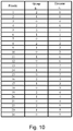
- a group-element utilisation order may be generated, which may take the form of a 24-element ordered list, which may be encoded in 15 bytes, each list entry specifying a subdescriptor group and an element index, as illustrated in Figure 10 .
- the group-element utilisation order of Figure 10 is merely an example, and different group-element utilisation orders may be generated by changing the priorities of the entries in the list.
- the group-element utilisation order of Figure 10 is much more economical than the element utilisation order of Figure 6 , in terms of length and encoding size.
- Figure 10 shows a group-element priority list whereby element vo of group g 2 is given the highest priority, instructing the encoder that the first four elements to encode are v 5,0 , v 6,0 , v 9,0 and v 10,0 , element vo of group g 1 is given the second highest priority, instructing the encoder that the next eight elements to encode are v 1,0 , v 2,0 , v 4,0 , v 7,0 , v 8,0 , v 11,0 , v 13,0 and v 14,0 , etc.
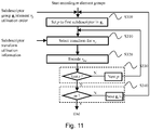
- Figure 11 illustrates the operation of such an encoder using the group-element utilisation order of Figure 10 and configured to encode the top m groups of elements in said group-element utilisation order.
- the encoding of the descriptor begins with the group of elements with the top priority (Priority 1) in the group-element utilisation order, i.e. element v 0 of group g 2 comprising subdescriptors v 5 , v 6 , v 9 , and v 10 .
- the encoding of the descriptor begins at the first subdescriptor of the group, i.e. v 5 .
- step S310 the appropriate transform is selected for the subdescriptor, for example according to the transform utilisation of Figure 3 .
- the computation of descriptor V from descriptor H according to two different transforms as described here is only an example. In different embodiments, the computation of descriptor V from descriptor H may also be performed according to a single transform, for example only Transform A or only Transform B, rendering step S310 unnecessary, or according to more than two transforms.
- the encoding of the element i.e. v 5,0 , takes place in step S320.
- step S330 if the current subdescriptor is not the last subdescriptor in the group, the processing moves to the next subdescriptor, otherwise the processing moves to step S340.
- steps S300, S330 and S340 relate to the order in which the processing is performed and to the control of how many groups of elements to encode, while steps S310 and S320 relate to the actual encoding of the local image descriptor.
- the number of groups m or corresponding number of elements l in the descriptor may be stored/transmitted alongside the descriptor, possibly at the image level.
- the decoder must also know the encoding process and the element utilisation order to be able to process and compare descriptors for the purposes of the related computer vision applications, which means that the element utilisation order must be either fixed or transmitted alongside the descriptors.
- Different applications may need to change the element utilisation order, possibly at the image or sub-image level , for example by giving higher priority to the subdescriptors closest to the descriptor centre, or by giving higher priority to a specific class of element, e.g.
- the element utilisation order must be stored or transmitted alongside the descriptors.
- the group-element utilisation order of Figure 10 represents a much lower overhead than the element utilisation order of Figure 6 .
- the subdescriptor grouping may be fixed and known to both the encoder and the decoder, or may be transmitted alongside the descriptors. For example, for the grouping considered so far, the number of groups and the size of composition of each group may be encoded in less than 10 bytes.
- group g 0 contains subdescriptors of varying distances to the descriptor centre, but always further away from the centre than the subdescriptors of group g 0 .
- the corresponding elements of the subdescriptors of the group are all assigned the same encoding priority.
- a group-element utilisation order may be generated, which may take the form of a 16-element ordered list, which may be encoded in 8 bytes, each list entry specifying a subdescriptor group and an element index, as illustrated in Figure 13 .
- the encoder of Figure 11 may then be used again to encode a descriptor according to the group-element utilisation order of Figure 13 .
- the group-element utilisation order of Figure 13 is merely an example, and different group-element utilisation orders may be generated by changing the priorities of the entries in the list.
- the subdescriptors of groups g 1 and g 2 are the same distance from the centre of the descriptor.
- This grouping is obtained from the grouping of Figure 9 by subdividing original group g 1 into new groups g 1 and g 2 .
- the advantage of this is that it results in groups with the same number of subdescriptors, which is desirable in optimised encoder implementations.
- the corresponding elements of the subdescriptors of the group are all assigned the same encoding priority.
- a group-element utilisation order may be generated, which may take the form of a 32-element ordered list, which may be encoded in 20 bytes, each list entry specifying a subdescriptor group and an element index, as illustrated in Figure 15 .
- the encoder of Figure 11 may then be used again to encode a descriptor according to the group-element utilisation order of Figure 15 .
- the group-element utilisation order of Figure 15 is merely an example, and different group-element utilisation orders may be generated by changing the priorities of the entries in the list.
- Figure 14 the grouping of Figure 14 into four groups is not unique.
- the subdescriptors are grouped firstly according to their distance from the centre (first condition) and secondly according their reciprocal distances (second condition).
- the distance between subdescriptors may again take the form of a Euclidean distance or another suitable distance measures, such as Manhattan distance.
- the second condition may be, for example, that a group should not contain subdescriptors whose distance to each other is below a predetermined threshold.
- the predetermined threshold may be set to prevent, for example, grouping neighbouring subdescriptors.
- the aim of the secondary condition is to ensure that the subdescriptors of different groups are, whenever possible, drawn from relatively distant positions of the subdescriptor grid, thereby increasing the information content of descriptors of very low numbers of features. It should be noted that the secondary condition may not always be satisfied, e.g. it is not possible to satisfy it for a group which contains all the central subdescriptors v 5 , v 6 , v 9 , and v 10 .
- the subdescriptors of groups g 0 , g 1 and g 2 satisfy the condition that they contain no neighbouring subdescriptors.
- the corresponding elements of the subdescriptors of the group are all assigned the same encoding priority.
- a group-element utilisation order such as the one illustrated in Figure 15 may be generated, and an encoder such as the one illustrated in Figure 11 may then be used again to encode a descriptor according to the group-element utilisation order of Figure 15 .
- the subdescriptors are grouped according to their distance from the centre and the subdescriptors of each group are encoded in a sequence defined according to their corresponding encoding characteristics, such as their corresponding transforms.
- g 0 ⁇ v 0 , v 15 , v 3 , v 12 ⁇ , containing the subdescriptors with the greatest distance to the descriptor centre
- g 1 ⁇ v 7 , v 8 , v 1 , v 14 ⁇ , containing a set of four subdescriptors with the second greatest distance to the descriptor centre
- g 2 ⁇ v 2 , v 13 , v 4 , v 11 ⁇ , containing a set of four different subdescriptors again with the second greatest distance to the descriptor centre
- g 3 ⁇ v 5 , v 10 , v 6 , v 9 ⁇ , containing the subdescriptors with the smallest distance to the descriptor centre.
- the corresponding elements of the subdescriptors of the group are all assigned the same encoding priority. Furthermore, within each group, the transform utilisation information for the four subdescriptors in the group is always "A A B B", which means than an efficient encoder implementation does not need to identify the applicable transform of each subdescriptor.
- Figure 18 illustrates the operation of such an encoder using the group-element utilisation order of Figure 15 and configured to encode the top m groups of elements in said group-element utilisation order.
- the encoding of the descriptor begins with the group of elements with the top priority (Priority 1) in the group-element utilisation order, i.e. element v 0 of group g 3 comprising subdescriptors v 5 , v 10 , v 6 , and v 9 .
- the encoding of the descriptor begins at the first subdescriptor of the group, i.e. v 5 .
- step S410 processing moves to step S410 where the encoding of the element, i.e. v 5,0 , takes place.
- step S420 if the current subdescriptor is not the last subdescriptor in the group, the processing moves to the next subdescriptor, otherwise the processing moves to step S430.
- step S430 if the desired number of m groups of elements has not yet been encoded, the processing moves to the group of elements with the next highest priority in the group-element utilisation order, otherwise the processing ends.
- steps S400, S420 and S430 relate to the order in which the processing is performed and to the control of how many groups of elements to encode, while only step S410 relates to the actual encoding of the local image descriptor.
- the common encoding sequence condition is defined on the transforms which are utilised within each group, but this condition may also be defined on other encoding characteristics, such as the type and level of quantisation, or combinations thereof.
- an encoding sequence condition that the transform utilisation sequence must be "A A B B” may be applied to groups g 0 and g 2
- a different encoding sequence condition that the transform utilisation sequence must be "A A A A B B B B” may be applied to group g 1 .
- the subdescriptors are grouped according to their distance from the centre and the subdescriptors of each group are ordered according to their distances between them.
- the ordering condition may be, for example, that the distance between consecutive subdescriptors within a group should not be below a predetermined threshold.
- the predetermined threshold may be set to prevent, for example, consecutive neighbouring subdescriptors within a group.
- a different ordering condition may be, for example, that the distance between consecutive subdescriptors within a group is maximised.
- This ordering is particularly useful when employing large subdescriptor groups, to reduce the size of the group-element utilisation order, and partial group encoding, as explained below. It should be noted that this type of ordering may not always be possible, e.g. it is not possible to not have consecutive neighbouring descriptors for a group which contains all the central subdescriptors v 5 , v 6 , v 9 , and v 10 .
- the corresponding elements of the subdescriptors of the group are all assigned the same encoding priority.
- a group-element utilisation order such as the one illustrated in Figure 10 may be generated, and an encoder such as the one illustrated in Figure 11 may then be used again to encode a descriptor according to the group-element utilisation order of Figure 10 .
- an encoder such as the one illustrated in Figure 19 may be employed.
- each of the encoders of Figures 11 and 18 may be easily configured to encode descriptors of any length by partial encoding of the last group of elements when the desired descriptor length has been reached.
- Figure 19 shows such a modification of the encoder of Figure 11 .
- the encoder of Figure 19 is obtained by simply swapping steps S330 and S340 of the encoder of Figure 11 , allowing the encoder of Figure 19 to terminate the encoding of a group as soon as the desired number of elements has been encoded.
- an analogous modification is also applicable to the encoder of Figure 18 .
- the ordering of the subdescriptors within a group according to the distances between them is highly advantageous since it results in consecutive elements being drawn from relatively distant positions of the subdescriptor grid which, in the event of the partial encoding of a group, increases the information content of descriptors with a low number of features.
- the previous embodiments of the invention demonstrate efficient encoding of image descriptors according to a group-element utilisation order resulting from the grouping of subdescriptors into subdescriptor groups based on their distances from the descriptor centre and/or their distances to each other.
- subdescriptors may be grouped so that each subdescriptor within a group has an identical element utilisation set to all the other subdescriptors within a group.
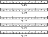
- the group-element utilisation sets of Figure 21a-21e may be converted into incremental group-element utilisation sets as illustrated in Figure 22a-22e where, for each descriptor length (for example DL2 of Figure 22c ), the corresponding element utilisation set shows only the additional elements which make up the descriptor of said descriptor length compared to the immediately lower descriptor length (for example DL1 of Figure 22b ).
- an encoder may generate descriptors which can be converted to lower descriptor lengths by simple descriptor truncation.
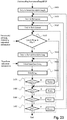
- Figure 23 illustrates the operation of such an encoder for the encoding of a descriptor of length DL k . More specifically, in step S600, the processing begins by encoding a descriptor of the lowest descriptor length, i.e. DL0. In step S610, the encoding of the DL0 descriptor begins with the encoding of the first subdescriptor group, i.e. g 0 , and in step S620 the encoding of the first subdescriptor group begins with the encoding of the first element, i.e. v 0 .
- step S630 if element v 0 is not in use for g 0 at descriptor length DL0 according to the incremental group-element utilisation sets of Figure 22 , the processing moves to step S680, otherwise the processing moves to step S640.
- step S640 the first subdescriptor of group g 0 is selected, i.e. v 5 , and in step S650 the appropriate transform function is selected, for example according to Figure 3 . It should be noted that the computation of descriptor V from descriptor H according to two different transforms as described here is only an example.
- the computation of descriptor V from descriptor H may also be performed according to a single transform, for example only Transform A or only Transform B, rendering step S650 unnecessary, or according to more than two transforms.
- Step 660 the encoding of element v 5,0 takes place.
- step S670 if the current subdescriptor is not the last subdescriptor in the group, the processing moves to the next subdescriptor in the group, otherwise the processing moves to step S680.
- step S680 if the current element is not the last element, i.e. v 7 , the processing moves to the next element, otherwise the processing moves to step S690.
- step S690 if the current subdescriptor group is not the last subdescriptor group, the processing moves to the next subdescriptor group, otherwise the processing moves to step S695.
- step S695 if the current subdescriptor length is not the target subdescriptor length, the processing moves to the next subdescriptor length, encoding the additional elements specified by the incremental group-element utilisation sets. Otherwise, the processing ends.
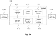
- Figure 24 illustrates a conceptual image processing apparatus for carrying out the method according to the present invention. More specifically, processing apparatus 1100 receives input, which may comprise visual data, such as image or video data, pre-calculated descriptors based on histograms of gradients, pre-calculated compact descriptors according to the method of the present invention, programming instructions, or user input, from input apparatus 1000, which may take the form of a user input apparatus, a media reader, or a receiver of transmitted signals.
- input apparatus 1000 may take the form of a user input apparatus, a media reader, or a receiver of transmitted signals.
- the processing apparatus 1100 comprises the main processing blocks of a central processing unit 1110 which controls the operations of the other processing blocks, volatile memory 1120, non-volatile memory 1130, optionally a descriptor extractor block 1140 configured to generate descriptors based on histograms of gradients, a compact descriptor encoder block 1150 configured to carry out the method according to the present invention, and optionally a compact descriptor processor block 1160 configured to process said compact descriptors, for example to establish or verify visual correspondences.
- Processing apparatus 1100 is connected to output apparatus 1900, which may take the form of a visual display unit, a media writer, or a transmitter of signals, which provides output which may comprise annotated visual data, such as image or video data, processing information such as established or verified visual correspondences, or compact descriptors according to the method of the present invention. It should be understood that the processing blocks and architecture shown in Figure 24 are only conceptual and may not correspond exactly to every apparatus implementing the method according to the invention.
- the present invention is not limited to a method for encoding an image descriptor based on a gradient histogram and a relative image processing apparatus, but may be subject to many modifications, improvements or replacements of equivalent parts and elements without departing from the inventive idea, as clearly specified in the following claims.
Landscapes
- Engineering & Computer Science (AREA)
- Multimedia (AREA)
- Signal Processing (AREA)
- Physics & Mathematics (AREA)
- General Physics & Mathematics (AREA)
- Theoretical Computer Science (AREA)
- Compression Or Coding Systems Of Tv Signals (AREA)
- Image Analysis (AREA)
- Compression Of Band Width Or Redundancy In Fax (AREA)
- Editing Of Facsimile Originals (AREA)
- Facsimile Image Signal Circuits (AREA)
- Image Processing (AREA)
- Information Retrieval, Db Structures And Fs Structures Therefor (AREA)
- Compression, Expansion, Code Conversion, And Decoders (AREA)
Abstract
Description
- The present invention relates to a method for efficiently encoding, transcoding, decoding and processing image descriptors computed in local regions around image interest keypoints and to an image processing device comprising means for encoding, transcoding, decoding and processing such descriptors.
- Such image descriptors have found wide applicability in many computer vision applications including object recognition, content-based image retrieval, and image registration, to name a few.
- Existing approaches to the encoding of such descriptors exhibit certain drawbacks.
- For example, existing encoding approaches result in descriptors which require parsing of the whole descriptors to perform transcoding, whereby a descriptor of a given descriptor length is converted to a descriptor of a different descriptor length, or to perform decoding and comparison of descriptors of different lengths.
- As another example, existing encoding approaches are inefficient in terms of encoding complexity because they ignore the commonalities and redundancies in the operations which are required to produce variable-length image descriptors.
- The not yet published Italian patent application no.
TO2012A000602 - In said not yet published Italian patent application encoding methods of said descriptors are disclosed which are more efficient than the prior art methods in terms of producing easily scalable bitstreams.
- Such descriptors are disclosed in the above mentioned not yet published Italian patent application no.
TO2012A000602 - Important aspects of the computation of robust, discriminative, scalable and compact image descriptors from image descriptors employing histograms of gradients, in particular a SIFT image descriptor, according to the not yet published Italian patent application no.
TO2012A000602 - Briefly, with the SIFT method, local image descriptors are formed as follows: first, a search across multiple images scales and locations is performed to identify and localise stable image keypoints that are invariant to scale and orientation; then, for each keypoint, one or more dominant orientations are determined based on local image gradients, allowing the subsequent local descriptor computation to be performed relative to the assigned orientation, scale and location of each keypoint, thus achieving invariance to these transformations. Then, local image descriptors around keypoints are formed as follows: first, gradient magnitude and orientation information is calculated at image sample points in a region around the keypoint; then, these samples are accumulated into orientation histograms summarizing the contents over n×n subregions.
- By way of illustration only, an example of a SIFT keypoint descriptor is shown in
Figures 1a and 1b , whereFigure 1a shows a subdivision of a local region R into 4×4 subregions SR andFigure 1b shows a subdivision of the 360° range of orientations into eight bins for each orientation histogram, with the length of each arrow corresponding to the magnitude of that histogram entry. Thus, a local image descriptor as illustrated inFigure 1 has 4x4x8 = 128 elements. More details of the SIFT technique can be found in David G. Lowe, "Distinctive image features from scale-invariant keypoints," International Journal of Computer Vision, 60, 2 (2004), pp. 91-110. - According to the not yet published Italian patent application no.
TO2012A000602 - In the following description, H in an entire SIFT descriptor comprising 16 histograms of gradients h each with eight bins h, whereas V is an entire local descriptor according to the present invention comprising 16 subdescriptors v each with eight elements v.
- Let H denote a SIFT local image descriptor comprising 16 histograms of gradients h 0 - h 15, as shown in
Figure 2a , each histogram comprising eight bin values h 0 - h 7 , as shown inFigure 2b . A more robust, discriminative, scalable and compact image descriptor may be computed by transforming each of h 0 - h 15 of H and then performing scalar quantisation on the resultant transformed values. More specifically, each of h 0 - h 15 is transformed according to Transform A or Transform B, as shown below, according to the transform utilisation information ofFigure 3 , i.e. Transform A is applied to h 0, h 2, h 5, h 7, h 8, h 10, h 13, h 15 and Transform B is applied to h 1, h 3, h 4, h 6, h 9, h 11, h 12, h 14, giving the transformed descriptor V with subdescriptors v 0 - v 15, corresponding to h 0 - h 15 respectively, and each comprising elements v0-v7, giving a total of 128 elements.

- Then, each element undergoes coarse scalar quantisation, for example ternary (3-level) quantisation, with the quantisation thresholds selected so as to achieve a specific occurrence probability distribution among the quantisation bins for each element. This scalar quantisation produces the quantised descriptor V,∼ with subdescriptors v,∼ 0 - v,∼ 15, each comprising elements v,∼ 0 -v,∼ 7 , again with a total of 128 elements. This compact descriptor captures the most discriminative and robust information contained in the original histograms of gradients, in the form of the shape of the distributions and the relationship among their bin values.
- A key advantage of descriptor V, as well as its quantised version V,∼, is that it is highly scalable, and its dimensionality may be easily reduced if required by an application's storage requirements or a transmission channel's characteristics by simply eliminating one or more of its elements. For the sake of simplicity, in the description that follows there will be described important aspects of the invention in terms of the encoding of pre-quantised descriptor V with subdescriptors v 0 - v 15, each comprising elements v 0 -v 7 and, unless otherwise stated, it should be understood that the encoding of the quantised descriptor V,∼ proceeds in a similar manner.
-
Figures 4a-4e show exemplary sets of elements which have been found to produce excellent discriminative power and robustness for five target descriptor lengths, from descriptor length 0 (DL0), the shortest descriptor length utilising only 20 descriptor elements, to descriptor length 4 (DL4), the longest descriptor length utilising all 128 elements. More specifically,Figure 4a shows an exemplary set of elements for descriptor length DL0 comprising 20 elements,Figure 4b shows an exemplary set of elements for descriptor length DL1 comprising 40 elements,Figure 4c shows an exemplary set of elements for descriptor length DL2 comprising 64 elements,Figure 4d shows an exemplary set of elements for descriptor length DL3 comprising 80 elements, andFigure 4e shows an exemplary set of elements for descriptor length DL4 comprising all 128 elements. Thus, for each descriptor length, each element of each subdescriptor will or will not be encoded according to the element utilisation sets ofFigure 4a-4e . - Key to this scalability property is that the set of utilised elements for each descriptor length must be the same as or a subset of the set of utilised elements for all higher descriptor lengths, as illustrated in
Figures 4a-4e . This allows the transcoding and comparison of descriptors of different lengths by simple elimination of the excess elements of the descriptor with the higher descriptor length so that it is reduced to the same set of elements as the descriptor with the lower descriptor length. - A straightforward encoding method of this descriptor comprises calculating and encoding the elements in a "by-subdescriptor" order, i.e. in the general case as v 0,0, v 0,1, ..., v 0,7, v 1,0, v 1,1, ..., v 1,7 , ..., v 15,0, v 15,1, ..., v 15,7 where vi,j denotes element vj of subdescriptor v i . This means encoding elements v 0, v 1, ..., v 7 for transformed histogram v 0, then encoding elements v 0, v 1, ..., v 7 for transformed histogram v 1, etc., using the appropriate transforms, for example as illustrated in
Figure 3 , and also using the appropriate element utilisation sets for the desired descriptor length, for example as illustrated inFigure 4 , to decide which elements should be encoded. - This encoding results, for example for a descriptor length DL0, to a descriptor v 0,0, v 1,0, v 2,0, v 3,0, v 4,0, v 5,0, v 5,6, v 6,0, v 6,6, v 7,0, v 8,0, v 9,0, v 9,6, v 10,0, v 10,6, v 11,0, v 12,0, v 13,0, v 14,0, v 15,0 and for a descriptor length DL1 to a descriptor v 0,0, v 0,1, v 1,0, v 1,1, v 2,0, v 2,1, v 3,0, v 3,1, v 4,0, v 4,1, v 5,0, v 5,1, v 5,2, v 5,6, v 6,0, v 6,1, v 6,2, v 6,6, v 7,0, v 7,1, v 8,0, v 8,1, v 9,0, v 9,1, v 9,2, v 9,6, v 10,0, v 10,1, v 10,2, v 10,6, v 11,0, v 11,1, v 12,0, v 12,1, v 13,0, v 13,1, v 14,0, v 14,1, v 15,0, v 15,1.
Figure 5 illustrates the operation of such a straightforward encoder as a sequence of steps. In the following description, as well as in subsequent descriptions of an encoder's operation, unless otherwise specified, such a sequence of steps corresponds to steps which are conceptual and do not correspond to specific hardware of software implementations, components and instructions, but are representative of the overall operation of the encoder. More specifically,Figure 5 illustrates the operation of an encoder for a descriptor length DLk, for example corresponding to one of the descriptor lengths illustrated inFigure 4 . In step S100 ofFigure 5 , the encoding of the descriptor begins at the first subdescriptor, i.e. v 0. In step S110, the appropriate transform is selected for the subdescriptor being processed, for example according to the transform utilisation ofFigure 3 . It should be noted that the computation of descriptor V from descriptor H according to two different transforms as described here is only an example. The computation of descriptor V from descriptor H may also be performed according to a single transform, for example only Transform A or only Transform B, rendering step S110 unnecessary, or according to more than two transforms. In step S120, the encoding of the subdescriptor being processed begins at the first subdescriptor element, i.e. v 0. Then, in step S130, the use or not of the particular element of the particular subdescriptor, i.e. v 0,0 is checked against the element utilisation information for descriptor length DLk, for example using one of the utilisation sets ofFigure 4 . If the element is not in use, then processing moves to step S150. If the element is in use for the descriptor length DLk, then its encoding takes place in step S140. Here, as well as in subsequent descriptions of an encoder's operation, unless otherwise specified, the word "encoding" means one or more actions, or combination thereof, that make the element v 0,0 part of the local image descriptor, said actions including, but way of example and without limitation, the calculation according to the appropriate transform function of (1) or (2) seen earlier, the selection of the element for inclusion into the local image descriptor in the case all elements are pre-calculated without knowledge of which elements will be finally used in the descriptor, the quantisation of the element value, the storage of the element in volatile or non-volatile memory and the transmission of the element along a transmission channel. After step S140, or if it was decided that the element is not in use for the descriptor length DLk in step S130, the processing moves to step S150. In step S150, if the current element is not the last element of the subdescriptor, the processing moves to the next element of the subdescriptor, otherwise the processing moves to step S160. In step S160, if the current subdescriptor is not the last subdescriptor of the local image descriptor, the processing moves to the next subdescriptor of the local image descriptor, otherwise the processing ends. Thus, it is clear that steps S100, S120, S150, and S160 relate to the order in which the processing is performed, while steps S110, S130 and S140 relate to the actual encoding of the local image descriptor. - Another straightforward encoding method of this descriptor comprises calculating and encoding the elements in a "by-element" order, i.e. in the general case as v 0,0 v 1,0 , ..., v 15,0, v 0,1, v 1,1, ..., v 15,1 , ..., v 0,7, v 1,7, ..., v 15,7 i.e. encoding element vo for subdescriptors v 0, v 1,..., v 15, then encoding element v 1 for subdescriptors v 0, v 1,..., v 15, etc., again using the appropriate transforms, for example as illustrated in
Figure 3 , and also using the appropriate element utilisation sets for the desired descriptor length, for example as illustrated inFigure 4 , to decide which elements should be encoded. Such an encoder may operate in an analogous fashion to the encoder ofFigure 5 , with the appropriate reordering of steps. In general, neither of the two aforementioned methods offers an advantage over the other method. For the purposes of transcoding, decoding and processing, the decoder must also know the encoding process and the element ordering and utilisation sets to be able to process and compare descriptors, possibly of different lengths, for the purposes of the related computer vision applications. Thus, the element utilisation sets must be either permanently fixed or stored/transmitted alongside the descriptors. In this context, the straightforward encoding process is disadvantageous. - More specifically, such an encoding ignores the relative importance between different elements in the encoding order. Consequently, in terms of transcoding, whereby a descriptor of a given descriptor length is converted to a descriptor of a different descriptor length, or in terms of decoding and comparing descriptors of different lengths by comparing corresponding elements between the two descriptors, such an encoding necessitates parsing of the descriptors to achieve the desired result.
- Furthermore, such an encoding ignores the redundancy patterns in the relative importance between different elements and is unnecessarily complex with regards to deciding whether specific elements should be encoded or not.
- It is therefore an object of the present invention to disclose a method for encoding an image descriptor based on a gradient histogram, and relative image processing apparatus, which is more efficient with respect to the prior art methods.
- It is a further object of the present invention to disclose a method for encoding an image descriptor based on a gradient histogram, and relative image processing apparatus, which is more flexible.
- It is a further object of the present invention to disclose a method for encoding an image descriptor based on a gradient histogram, and relative image processing apparatus, which allows to achieve an optimised encoder implementation.
- It is a further object of the present invention to disclose a method for encoding an image descriptor based on a gradient histogram, and relative image processing apparatus, which allows to obtain image descriptors of any length. These and other objects of the invention are achieved through a method for encoding an image descriptor based on a gradient histogram, and relative image processing apparatus, as claimed in the appended claims, which are an integral part of the present description.
- Briefly, it is disclosed a method for efficiently encoding image descriptors such as the ones above described by encoding them according to an element utilisation order, resulting in scalable descriptors which can be converted to lower descriptor lengths by simple descriptor truncation instead of parsing. The encoding is carried out according to subdescriptor groups, formed according to the redundancy patterns in the relative importance between the corresponding elements of said subdescriptor groups.
- More specifically, said grouping is performed by grouping subdescriptors whose corresponding elements have a similar importance in an ordering of all the elements of the descriptor according to their relative importance in terms of achieving high recognition performance, more specifically by grouping subdescriptors according to their distance from the descriptor centre and additionally by grouping subdescriptors according to the distance between them and/or additionally by ordering the subdescriptors of a group according to corresponding encoding characteristics and/or additionally by ordering the subdescriptors of a group according to the distance between them.
- The encoding method according to the invention is advantageously more efficient that the prior art ones in terms of efficiency, of computational complexity and/or of the amount of information needed to generate scalable bitstreams.
- Further features of the invention are set out in the appended claims, which are intended as an integral part of the present description.
- The above objects will become more apparent from the following detailed description of the method for encoding an image descriptor based on a gradient histogram, and relative image processing apparatus, with particular reference to the annexed drawings, wherein:
-
Figure 1a and 1b show an example of a prior art keypoint descriptor; -
Figures 2a and 2b show histograms of gradients of the keypoint descriptor ofFigure 1 and bin values related to one of said histogram of gradients, respectively; -
Figure 3 shows exemplary transforms to be applied to the histograms of gradients ofFigure 2 ; -
Figures 4a-4e show exemplary sets of elements for five respective targets descriptor lengths; -
Figure 5 represents a flow-chart illustrating the operation of an encoder using the sets of elements ofFigure 4 ; -
Figure 6 shows an element utilisation order used by a method according to the present invention; -
Figure 7 illustrates the operation of an encoder using the element utilisation order ofFigure 6 ; -
Figure 8 shows the centres of a region and of a subregion of a local image descriptor; -
Figure 9 shows a first grouping of subdescriptors of a local image descriptor according to a first embodiment or a fourth embodiment of a method according to the invention; -
Figures 12 and14 show second and third exemplary groupings, respectively, of subdescriptors of a local image descriptor according to the first embodiment of a method according to the invention; -
Figures 10 ,13 and15 show first, second and third group-element utilisation orders relating to the groupings ofFigures 9 ,12 ,14 and17 , respectively; -
Figure 11 illustrates the operation of an encoder according to a first, second or fourth embodiment of a method according to the invention; -
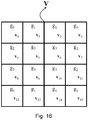
Figure 16 shows a fourth exemplary grouping according to a first embodiment of a method according to the invention; -
Figure 17 shows a fifth exemplary grouping of subdescriptors of a local image descriptor according to the second and third embodiment of a method according to the invention; -
Figure 18 illustrates the operation of an encoder using the element utilisation order ofFigure 17 , according to third embodiment of a method according to the invention; -
Figure 19 illustrates the operation of an encoder according to a fourth embodiment of a method according to the invention; -
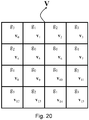
Figure 20 shows an exemplary grouping of subdescriptors of a local image descriptor according to a fifth embodiment of a method according to the invention; -
Figures 21a-21e show exemplary sets of elements according to the grouping ofFigure 20 ; -
Figures 22a-22e show the sets of elements ofFigures 21a-21e , respectively, when converted into group-element utilisation sets; -
Figure 23 illustrates the operation of an encoder for the encoding of a descriptor for providing the converted sets of elements ofFigures 22a-22e ; -
Figure 24 illustrates an image processing device suitable for carrying out the method according to the present invention. - According to the invention, rather than encoding according to element utilisation sets for different descriptor lengths, a more efficient encoder may operate according to an element utilisation order, producing a descriptor whose elements are ordered according to the element utilisation order and which can be converted to lower descriptor lengths by simple descriptor truncation. Such an element utilisation order may take the form of a 128-element ordered list, which may be encoded in 112 bytes, each list entry specifying a subdescriptor index and an element index, as illustrated in
Figure 6 . So, for example,Figure 6 shows an element priority list whereby element v 5,0 is given the highest priority, element v 9,0 is given the second highest priority, etc. Therefore, such an element utilisation order encoder may produce a descriptor of length l by encoding the top l elements in the list. -
Figure 7 illustrates the operation of such an encoder using the element utilisation order ofFigure 6 . With the encoder ofFigure 7 , the encoding of the descriptor begins with the element with the top priority (Priority 1) in the element utilisation order, i.e. element v 0 of subdescriptor v 5. In step S200, the appropriate transform is selected according to the subdescriptor to which this element belongs, for example according to the transform utilisation ofFigure 3 . It should be noted that the computation of descriptor V from descriptor H according to two different transforms as described here is only an example. In different embodiments, the computation of descriptor V from descriptor H may also be performed according to a single transform, for example only Transform A or only Transform B, rendering step S200 unnecessary, or according to more than two transforms. Then, the encoding of the element, i.e. v 5,0, takes place in step S210. Then, in step S220, if a desired number of l elements of the descriptor has not yet been encoded, the processing moves to the element with the next highest priority in the element utilisation order, otherwise the processing ends. Thus, step S220 relates to the control of how many elements to encode, while steps S200 and S210 relate to the actual encoding of the local image descriptor. - Thus, the encoder of
Figure 7 , using an element utilisation order as inFigure 6 , produces descriptors whose elements are ordered according to the element utilisation order and which can be converted to lower descriptor lengths by simple descriptor truncation, i.e. eliminating the last elements of the descriptor, and is more flexible than the encoder ofFigure 5 which uses element utilisation sets as inFigure 4 . - The number of elements l in the descriptor may be stored/transmitted alongside the descriptor, possibly at the image level. For the purposes of transcoding, decoding and processing, the decoder must also know the element ordering to be able to process for the purposes of the related computer vision applications. Thus, the element utilisation order must be either permanently fixed or stored/transmitted alongside the descriptors.
- In practice, however, the efficiency of the encoder of
Figure 7 can be improved. This is because the element utilisation order illustrated inFigure 6 contains a significant amount of redundancy and is, to some extent, impractical to generate and use. - The reason for this is that the complete set of 128 elements of V do not correspond to a single descriptor whose elements may be ordered according to a single priority list, but to 16 different 8-element subdescriptors, each subdescriptor extracted from a different histogram of gradients according to a specific transform and so that corresponding elements between all subdescriptors capture the relation between bins with the same angular separation.
- Thus, it has been found that, in terms of achieving a high recognition performance with a limited set of elements, a descriptor needs to strike a balance between a uniform element distribution, i.e. selecting element(s) from as many subdescriptors as possible, and distance from the descriptor centre, i.e. giving higher priority to subdescriptors which are closer to the descriptor centre. At the same time, it has also been found that the importance of corresponding elements from different subdescriptors is approximately the same when the distance of the subdescriptors to the descriptor centre is the same, while the importance of corresponding elements from different subdescriptors increases as the distance of the subdescriptors to the descriptor centre decreases.
- In this context, the distance of a subdescriptor v to the descriptor centre refers to the distance between the centre of the subregion which corresponds to the histogram of gradients h which gives rise to the subdescriptor v and the centre of the region which comprises the subregions, as illustrated in
Figure 8 . While it is possible to refer back to the dimensions of the image region and subregions to compute said distances, it is not necessary since there is only interest in comparing said distances. Therefore said distances may be computed by assuming that each side of each subregion has, for example, a unit length. Furthermore, in this description said distances are Euclidean distances, although other suitable distance measures may also be used. - Consequently, it is observed that, for the purposes of efficient encoding of an image descriptor, its subdescriptors may be grouped so that corresponding descriptor elements for the subdescriptors of each group are assigned a common importance in the utilisation order and are encoded jointly.
- In a first embodiment of the invention, the subdescriptors are grouped according to their distance from the descriptor centre.
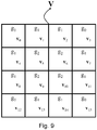
- For example, one such grouping is illustrated in
Figure 9 , where there are three groups, namely g 0 = {v 0, v 3, v 12, v 15}, containing the subdescriptors with the greatest distance to the descriptor centre, g 1 = {v 1, v 2, v 4, v 7, v 8, v 11, v 13, v 14}, containing the subdescriptors with the second greatest distance to the descriptor centre, and g 2 = {v 5, v 6, v 9, v 10}, containing the subdescriptors with the smallest distance to the descriptor centre. Within each group, the subdescriptors are ordered in ascending subdescriptor index order, although this is not restrictive and other orders may be used, such as clockwise starting from the top-most left-most subdescriptor in the group. Within each group, the corresponding elements of the subdescriptors of the group are all assigned the same encoding priority. - Based on this grouping, a group-element utilisation order may be generated, which may take the form of a 24-element ordered list, which may be encoded in 15 bytes, each list entry specifying a subdescriptor group and an element index, as illustrated in
Figure 10 . It should be noted that the group-element utilisation order ofFigure 10 is merely an example, and different group-element utilisation orders may be generated by changing the priorities of the entries in the list. Thus, the group-element utilisation order ofFigure 10 is much more economical than the element utilisation order ofFigure 6 , in terms of length and encoding size. So, for example,Figure 10 shows a group-element priority list whereby element vo of group g 2 is given the highest priority, instructing the encoder that the first four elements to encode are v 5,0, v 6,0 , v 9,0 and v 10,0, element vo of group g 1 is given the second highest priority, instructing the encoder that the next eight elements to encode are v 1,0, v 2,0 , v 4,0 , v 7,0, v 8,0, v 11,0 , v 13,0 and v 14,0, etc. -
Figure 11 illustrates the operation of such an encoder using the group-element utilisation order ofFigure 10 and configured to encode the top m groups of elements in said group-element utilisation order. With the encoder ofFigure 11 , the encoding of the descriptor begins with the group of elements with the top priority (Priority 1) in the group-element utilisation order, i.e. element v 0 of group g 2 comprising subdescriptors v 5, v 6, v 9, and v 10. In step S300, the encoding of the descriptor begins at the first subdescriptor of the group, i.e. v 5. In step S310, the appropriate transform is selected for the subdescriptor, for example according to the transform utilisation ofFigure 3 . It should be noted that the computation of descriptor V from descriptor H according to two different transforms as described here is only an example. In different embodiments, the computation of descriptor V from descriptor H may also be performed according to a single transform, for example only Transform A or only Transform B, rendering step S310 unnecessary, or according to more than two transforms. Then, the encoding of the element, i.e. v 5,0, takes place in step S320. In step S330, if the current subdescriptor is not the last subdescriptor in the group, the processing moves to the next subdescriptor, otherwise the processing moves to step S340. Then, in step S340, if the desired number of m groups of elements has not yet been encoded, the processing moves to the group of elements with the next highest priority in the group-element utilisation order, otherwise the processing ends. Thus, steps S300, S330 and S340 relate to the order in which the processing is performed and to the control of how many groups of elements to encode, while steps S310 and S320 relate to the actual encoding of the local image descriptor. - The number of groups m or corresponding number of elements l in the descriptor may be stored/transmitted alongside the descriptor, possibly at the image level.
- The fact that the group-element utilisation order of
Figure 10 is more economical than the element utilisation order ofFigure 6 results in a more efficient and economical encoder. Furthermore, as seen earlier, for the purposes of transcoding, decoding and processing, the decoder must also know the encoding process and the element utilisation order to be able to process and compare descriptors for the purposes of the related computer vision applications, which means that the element utilisation order must be either fixed or transmitted alongside the descriptors. Different applications may need to change the element utilisation order, possibly at the image or sub-image level, for example by giving higher priority to the subdescriptors closest to the descriptor centre, or by giving higher priority to a specific class of element, e.g. v 7 as opposed to v 2, in order to achieve high recognition performance with a limited set of elements. In this case, the element utilisation order must be stored or transmitted alongside the descriptors. Considering that low-bitrate descriptors are typically a few hundred bytes in size, the group-element utilisation order ofFigure 10 represents a much lower overhead than the element utilisation order ofFigure 6 . Furthermore, the subdescriptor grouping may be fixed and known to both the encoder and the decoder, or may be transmitted alongside the descriptors. For example, for the grouping considered so far, the number of groups and the size of composition of each group may be encoded in less than 10 bytes. - As another example according to a first embodiment of the invention, a different grouping is illustrated in
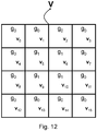
Figure 12 , where there are two groups, namely g 0 = {v 0, v 1, v 2, v 3, v 4, v 7, v 8, v 11, v 12, v 13, v 14, v 15}, containing all the peripheral subdescriptors, and g 1 = {v 5, v 6, v 9, v 10}, containing the subdescriptors with the smallest distance to the descriptor centre, i.e. all the central subdescriptors. Thus, with this example, group g 0 contains subdescriptors of varying distances to the descriptor centre, but always further away from the centre than the subdescriptors of group g 0. Within each group, the corresponding elements of the subdescriptors of the group are all assigned the same encoding priority. Based on this grouping, a group-element utilisation order may be generated, which may take the form of a 16-element ordered list, which may be encoded in 8 bytes, each list entry specifying a subdescriptor group and an element index, as illustrated inFigure 13 . The encoder ofFigure 11 may then be used again to encode a descriptor according to the group-element utilisation order ofFigure 13 . It should be noted that the group-element utilisation order ofFigure 13 is merely an example, and different group-element utilisation orders may be generated by changing the priorities of the entries in the list. - As another example according to a first embodiment of the invention, a different grouping is illustrated in
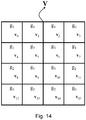
Figure 14 , where there are four groups, namely g 0 = {v 0, v 3, v 12, v 15}, containing the subdescriptors with the greatest distance to the descriptor centre, g 1 = {v 1, v 2, v 4, v 7}, containing a set of four subdescriptors with the second greatest distance to the descriptor centre, g 2 = {v 8, v 11, v 13, v 14}, containing a set of four different subdescriptors again with the second greatest distance to the descriptor centre, and g 3 = {v 5, v 6, v 9, v 10}, containing the subdescriptors with the smallest distance to the descriptor centre. Thus, with this example, the subdescriptors of groups g 1 and g 2 are the same distance from the centre of the descriptor. This grouping is obtained from the grouping ofFigure 9 by subdividing original group g 1 into new groups g 1 and g 2. The advantage of this is that it results in groups with the same number of subdescriptors, which is desirable in optimised encoder implementations. Within each group, the corresponding elements of the subdescriptors of the group are all assigned the same encoding priority. Based on this grouping, a group-element utilisation order may be generated, which may take the form of a 32-element ordered list, which may be encoded in 20 bytes, each list entry specifying a subdescriptor group and an element index, as illustrated inFigure 15 . The encoder ofFigure 11 may then be used again to encode a descriptor according to the group-element utilisation order ofFigure 15 . It should be noted that the group-element utilisation order ofFigure 15 is merely an example, and different group-element utilisation orders may be generated by changing the priorities of the entries in the list. - Clearly, the grouping of
Figure 14 into four groups is not unique. For example, an alternative grouping is shown inFigure 16 , containing groups g 0 = {v 0, v 3, v 12, v 15}, g 1 = {v 1, v 2, v 13, v 14}, g 2 = {v 4, v 7, v 8, v 11}, and g 3 = {v 5, v6, v 9, v 10}. Thus, inFigure 16 groups g 0 and g 3 are identical to those ofFigure 14 , but the subdescriptors of g 1 and g 2 have been swapped compared toFigure 14 so that each of those two groups contains one subdescriptor from the upper-left, upper-right, lower-left and lower-right part of the subdescriptor grid. - One difference between the encoder of
Figure 7 and the encoder ofFigure 11 is that, unlike the former which produces descriptors of any length, the latter allow encoding of descriptors whose length has a granularity decided by the subdescriptor groups. In practice, the latter may be configured to produce descriptors of any length, as will be demonstrated later. - In a second embodiment of the invention, the subdescriptors are grouped firstly according to their distance from the centre (first condition) and secondly according their reciprocal distances (second condition).
- In this context, the distance between subdescriptors may again take the form of a Euclidean distance or another suitable distance measures, such as Manhattan distance.
- The second condition may be, for example, that a group should not contain subdescriptors whose distance to each other is below a predetermined threshold. Thus, the predetermined threshold may be set to prevent, for example, grouping neighbouring subdescriptors.
- The aim of the secondary condition is to ensure that the subdescriptors of different groups are, whenever possible, drawn from relatively distant positions of the subdescriptor grid, thereby increasing the information content of descriptors of very low numbers of features. It should be noted that the secondary condition may not always be satisfied, e.g. it is not possible to satisfy it for a group which contains all the central subdescriptors v 5, v 6, v 9, and v 10. For example, one such grouping is illustrated in
Figure 17 , where there are four groups, namely g 0 = {v 0, v 3, v 12, v 15}, containing the subdescriptors with the greatest distance to the descriptor centre, g 1 = {v 1, v 7, v 8, v 14}, containing a set of four subdescriptors with the second greatest distance to the descriptor centre, g 2 = {v 2, v 4, v 11, v 13}, containing a set of four different subdescriptors again with the second greatest distance to the descriptor centre, and g 3 = {v 5, v 6, v 9, v 10}, containing the subdescriptors with the smallest distance to the descriptor centre. Thus, with this example, the subdescriptors of groups g 0, g 1 and g 2 satisfy the condition that they contain no neighbouring subdescriptors. Within each group, the corresponding elements of the subdescriptors of the group are all assigned the same encoding priority. Based on this grouping, a group-element utilisation order such as the one illustrated inFigure 15 may be generated, and an encoder such as the one illustrated inFigure 11 may then be used again to encode a descriptor according to the group-element utilisation order ofFigure 15 . - Clearly, alternative conditions based on the distance of subdescriptors within a group may also be employed, such as maximising the total distance between subdescriptors, etc.
- In a third embodiment of the invention, the subdescriptors are grouped according to their distance from the centre and the subdescriptors of each group are encoded in a sequence defined according to their corresponding encoding characteristics, such as their corresponding transforms.
- For example, considering the grouping of
Figure 17 of the second embodiment of the invention in conjunction with the transform deployment pattern ofFigure 3 , it can be seen that, within each group, two subdescriptors are transformed according to transform A and two subdescriptors are transformed according to transform B. Therefore, it is possible to set a common encoding sequence condition that, for each group, the transform utilisation sequence must be "A A B B", i.e. an encoding sequence whereby, for each subdescriptor group, the transform of the first subdescriptor in the group is transform A, the transform of the second subdescriptor in the group is also transform A, the transform of the third subdescriptor in the group is transform B, and the transform of the fourth subdescriptor in the group is also transform B. Thus, there are groups g 0 = {v 0, v 15, v 3, v 12}, containing the subdescriptors with the greatest distance to the descriptor centre, g 1 = {v 7, v 8, v 1, v 14}, containing a set of four subdescriptors with the second greatest distance to the descriptor centre, g 2 = {v 2, v 13, v 4, v 11}, containing a set of four different subdescriptors again with the second greatest distance to the descriptor centre, and g 3 = {v 5, v 10, v 6, v 9}, containing the subdescriptors with the smallest distance to the descriptor centre. Within each group, the corresponding elements of the subdescriptors of the group are all assigned the same encoding priority. Furthermore, within each group, the transform utilisation information for the four subdescriptors in the group is always "A A B B", which means than an efficient encoder implementation does not need to identify the applicable transform of each subdescriptor. -
Figure 18 illustrates the operation of such an encoder using the group-element utilisation order ofFigure 15 and configured to encode the top m groups of elements in said group-element utilisation order. With the encoder ofFigure 18 , the encoding of the descriptor begins with the group of elements with the top priority (Priority 1) in the group-element utilisation order, i.e. element v 0 of group g 3 comprising subdescriptors v 5, v 10, v 6, and v 9. In step S400, the encoding of the descriptor begins at the first subdescriptor of the group, i.e. v 5. Given that all groups have a common and fixed transform utilisation order, processing moves to step S410 where the encoding of the element, i.e. v 5,0, takes place. In step S420, if the current subdescriptor is not the last subdescriptor in the group, the processing moves to the next subdescriptor, otherwise the processing moves to step S430. Then, in step S430, if the desired number of m groups of elements has not yet been encoded, the processing moves to the group of elements with the next highest priority in the group-element utilisation order, otherwise the processing ends. Thus, steps S400, S420 and S430 relate to the order in which the processing is performed and to the control of how many groups of elements to encode, while only step S410 relates to the actual encoding of the local image descriptor. - In the above description, the common encoding sequence condition is defined on the transforms which are utilised within each group, but this condition may also be defined on other encoding characteristics, such as the type and level of quantisation, or combinations thereof.
- Clearly, if required, different encoding sequence conditions may be applied to different groups of subdescriptors. For example, in the first embodiment of the invention, the grouping according to
Figure 9 results in three groups, namely go, containing the four subdescriptors with the greatest distance to the descriptor centre, g 1, containing the eight subdescriptors with the second greatest distance to the descriptor centre, and g 2, containing the four subdescriptors with the smallest distance to the descriptor centre. In this case, because of the different group size, an encoding sequence condition that the transform utilisation sequence must be "A A B B" may be applied to groups g 0 and g 2, and a different encoding sequence condition that the transform utilisation sequence must be "A A A A B B B B" may be applied to group g 1. - In a fourth embodiment of the invention, the subdescriptors are grouped according to their distance from the centre and the subdescriptors of each group are ordered according to their distances between them.
- The ordering condition may be, for example, that the distance between consecutive subdescriptors within a group should not be below a predetermined threshold. Thus, the predetermined threshold may be set to prevent, for example, consecutive neighbouring subdescriptors within a group. A different ordering condition may be, for example, that the distance between consecutive subdescriptors within a group is maximised.
- This ordering is particularly useful when employing large subdescriptor groups, to reduce the size of the group-element utilisation order, and partial group encoding, as explained below. It should be noted that this type of ordering may not always be possible, e.g. it is not possible to not have consecutive neighbouring descriptors for a group which contains all the central subdescriptors v 5, v 6, v 9, and v 10.
- For example, considering the grouping illustrated in
Figure 9 , it can be seen that the subdescriptors within each group may be ordered to maximise the distance between consecutive subdescriptors, starting from the subdescriptor with the lowest index within the group, resulting in groups g 0 = {v 0, v 15, v 3, v 12}, g 1 = {v 1, v 14, v 2, v 13, v 7, v 8, v 11, v 4}, and g 2 = {v 5 , v 10, v 6, v 9}. Within each group, the corresponding elements of the subdescriptors of the group are all assigned the same encoding priority. - Based on this grouping and ordering of subdescriptors within each group, a group-element utilisation order such as the one illustrated in
Figure 10 may be generated, and an encoder such as the one illustrated inFigure 11 may then be used again to encode a descriptor according to the group-element utilisation order ofFigure 10 . Alternatively, an encoder such as the one illustrated inFigure 19 may be employed. - More specifically, one difference between the encoder of
Figure 7 and the encoders ofFigure 11 andFigure 18 is that, unlike the former which produces descriptors of any length, the latter allow encoding of descriptors whose length has a granularity decided by the subdescriptor groups. In practice, however, each of the encoders ofFigures 11 and18 may be easily configured to encode descriptors of any length by partial encoding of the last group of elements when the desired descriptor length has been reached. In this context,Figure 19 shows such a modification of the encoder ofFigure 11 . In essence, the encoder ofFigure 19 is obtained by simply swapping steps S330 and S340 of the encoder ofFigure 11 , allowing the encoder ofFigure 19 to terminate the encoding of a group as soon as the desired number of elements has been encoded. Clearly, an analogous modification is also applicable to the encoder ofFigure 18 . - In this context, the ordering of the subdescriptors within a group according to the distances between them is highly advantageous since it results in consecutive elements being drawn from relatively distant positions of the subdescriptor grid which, in the event of the partial encoding of a group, increases the information content of descriptors with a low number of features.
- The previous embodiments of the invention demonstrate efficient encoding of image descriptors according to a group-element utilisation order resulting from the grouping of subdescriptors into subdescriptor groups based on their distances from the descriptor centre and/or their distances to each other.
- In an alternative embodiment of the invention, subdescriptors may be grouped so that each subdescriptor within a group has an identical element utilisation set to all the other subdescriptors within a group.
- For example, consider the grouping of
Figure 20 , where there are four groups, namely g 0 = {v 5, v 6, v 9, v 10}, g 1 = {v 1, v 7, v 8, v 14}, g 2 = {v 2, v 4, v 11, v 13}, and g 3 = {v 0, v 3, v 12, v 15}. This is the same grouping as inFigure 17 , but with group indexes reassigned (i.e. g 0 and g 3 have been swapped) so that groups with lower indexes contain subdescriptors which are closer to the descriptor centre. Combining this grouping with the element utilisation sets ofFigure 4a-4e leads to the group-element utilisation sets ofFigure 21a-21e . - Since the set of utilised elements for each descriptor length must be the same as or a subset of the set of utilised elements for all higher descriptor lengths, the group-element utilisation sets of
Figure 21a-21e may be converted into incremental group-element utilisation sets as illustrated inFigure 22a-22e where, for each descriptor length (for example DL2 ofFigure 22c ), the corresponding element utilisation set shows only the additional elements which make up the descriptor of said descriptor length compared to the immediately lower descriptor length (for example DL1 ofFigure 22b ). - Based on the incremental group-element utilisation sets of
Figure 22a-22e , an encoder may generate descriptors which can be converted to lower descriptor lengths by simple descriptor truncation. -
Figure 23 illustrates the operation of such an encoder for the encoding of a descriptor of length DLk. More specifically, in step S600, the processing begins by encoding a descriptor of the lowest descriptor length, i.e. DL0. In step S610, the encoding of the DL0 descriptor begins with the encoding of the first subdescriptor group, i.e. g 0, and in step S620 the encoding of the first subdescriptor group begins with the encoding of the first element, i.e. v 0 . In step S630, if element v 0 is not in use for g 0 at descriptor length DL0 according to the incremental group-element utilisation sets ofFigure 22 , the processing moves to step S680, otherwise the processing moves to step S640. In step S640 the first subdescriptor of group g 0 is selected, i.e. v 5, and in step S650 the appropriate transform function is selected, for example according toFigure 3 . It should be noted that the computation of descriptor V from descriptor H according to two different transforms as described here is only an example. In different embodiments, the computation of descriptor V from descriptor H may also be performed according to a single transform, for example only Transform A or only Transform B, rendering step S650 unnecessary, or according to more than two transforms. Then in Step 660, the encoding of element v 5,0 takes place. In step S670, if the current subdescriptor is not the last subdescriptor in the group, the processing moves to the next subdescriptor in the group, otherwise the processing moves to step S680. In step S680, if the current element is not the last element, i.e. v7, the processing moves to the next element, otherwise the processing moves to step S690. In step S690, if the current subdescriptor group is not the last subdescriptor group, the processing moves to the next subdescriptor group, otherwise the processing moves to step S695. In step S695, if the current subdescriptor length is not the target subdescriptor length, the processing moves to the next subdescriptor length, encoding the additional elements specified by the incremental group-element utilisation sets. Otherwise, the processing ends. - Although aspects and embodiments of the present invention are presented in detail for the computation of robust, discriminative, scalable and compact image descriptors from a SIFT image descriptor, the invention is applicable to other image descriptors based on histograms of gradients, as outlined in the not yet published Italian patent application no.
TO2012A000602 - By way of example only,
Figure 24 illustrates a conceptual image processing apparatus for carrying out the method according to the present invention. More specifically,processing apparatus 1100 receives input, which may comprise visual data, such as image or video data, pre-calculated descriptors based on histograms of gradients, pre-calculated compact descriptors according to the method of the present invention, programming instructions, or user input, frominput apparatus 1000, which may take the form of a user input apparatus, a media reader, or a receiver of transmitted signals. Theprocessing apparatus 1100 comprises the main processing blocks of acentral processing unit 1110 which controls the operations of the other processing blocks,volatile memory 1120,non-volatile memory 1130, optionally adescriptor extractor block 1140 configured to generate descriptors based on histograms of gradients, a compactdescriptor encoder block 1150 configured to carry out the method according to the present invention, and optionally a compactdescriptor processor block 1160 configured to process said compact descriptors, for example to establish or verify visual correspondences.Processing apparatus 1100 is connected tooutput apparatus 1900, which may take the form of a visual display unit, a media writer, or a transmitter of signals, which provides output which may comprise annotated visual data, such as image or video data, processing information such as established or verified visual correspondences, or compact descriptors according to the method of the present invention. It should be understood that the processing blocks and architecture shown inFigure 24 are only conceptual and may not correspond exactly to every apparatus implementing the method according to the invention. - The method for encoding an image descriptor based on a gradient histogram and a relative image processing apparatus described herein by way of example may be subject to many possible variations without departing from the novelty spirit of the inventive idea; it is also clear that in the practical implementation of the invention the illustrated details may have different shapes or be replaced with other technically equivalent elements.
- It can therefore be easily understood that the present invention is not limited to a method for encoding an image descriptor based on a gradient histogram and a relative image processing apparatus, but may be subject to many modifications, improvements or replacements of equivalent parts and elements without departing from the inventive idea, as clearly specified in the following claims.
- Further embodiments are defined as E1 to E22 as follows:
- E1. Method for encoding an image descriptor (H) based on gradient histograms (h p) into a transformed descriptor (V) comprising transformed subdescriptors (v p), wherein each gradient histogram (h p) comprises a plurality of histogram bins (hi ) and each subdescriptor (v p) comprises a set of values (vj ), characterised in that said subdescriptors (v p) are generated according to an element utilisation order list specifying a subdescriptor index (p) of said set of subdescriptors (v p) and an element index (j) of said set of values (vj ).
- E2. Method according to
embodiment 1, wherein said subdescriptors (v p) are grouped into subdescriptor groups according to their distance from an image descriptor centre and wherein, within each subdescriptor group, corresponding values (vj ) of a subdescriptor group are all assigned a same encoding priority in said element utilisation order list. - E3. Method according to
embodiment 2, wherein said subdescriptors (v p) are grouped into a first group containing all the subdescriptors with the smallest distance to the image descriptor centre and a second group containing all the remaining subdescriptors. - E4. Method according to
embodiment 2, wherein said subdescriptors (v p) are grouped into a first group containing the subdescriptors with the greatest distance from the descriptor centre, a second group containing a first set of subdescriptors with the second greatest distance to the descriptor centre, a third group containing a second set of subdescriptors with the second greatest distance to the descriptor centre, and a fourth group containing the subdescriptors with the smallest distance to the descriptor centre. - E5. Method according to
embodiment 4, wherein said first, second, third and fourth group contains the same number of subdescriptors. - E6. Method according to
embodiment 1, wherein said subdescriptors (v p) are grouped into subdescriptor groups according to their distance from an image descriptor centre and according to their reciprocal distances and wherein, within each subdescriptor group, corresponding values (vj ) of a subdescriptor group are all assigned a same encoding priority in said element utilisation order list. - E7. Method according to
embodiment 6, wherein said subdescriptors (v p) are grouped into a first group containing the subdescriptors with the greatest distance from the descriptor centre, a second group containing a first set of subdescriptors with the second greatest distance to the descriptor centre, a third group containing a second set of subdescriptors with the second greatest distance to the descriptor centre, and a fourth group containing the subdescriptors with the smallest distance to the descriptor centre. - E8. Method according to
embodiment 6, wherein a subdescriptor group does not contain subdescriptors whose distance to each other is below a predetermined threshold. - E9. Method according to
embodiment 6, wherein said reciprocal distances comprises maximising the total distance between subdescriptors. - E10. Method according to
embodiment 1, wherein said subdescriptors (v p) are grouped into subdescriptor groups according to the distance from an image descriptor centre and are ordered according to the reciprocal distances and wherein, within each subdescriptor group, corresponding values (vj ) of a subdescriptor group are all assigned a same encoding priority in said element utilisation order list. - E11. Method according to
embodiment 10, wherein a subdescriptor group does not contain consecutive subdescriptors whose distance is below a predetermined threshold. - E12. Method according to
embodiment 10, wherein said reciprocal distances comprises maximising the distance between consecutive subdescriptors. - E13. Method according to
embodiment 1, wherein said subdescriptors (v p) are grouped into subdescriptor groups according to the distance from an image descriptor centre and the subdescriptors of each group are encoded in a sequence defined according to their corresponding encoding characteristics and wherein, within each subdescriptor group, corresponding values (vj ) of a subdescriptor group are all assigned a same encoding priority in said element utilisation order list. - E14. Method according to
embodiment 13, wherein said encoding characteristics are corresponding transforms. - E15. Method according to
embodiment 14, wherein, for each subdescriptor group, the transform of a first subdescriptor in the group is a first type of transform (A), the transform of a second subdescriptor in the group is said first type of transform (A), the transform of a third subdescriptor in the group is a second type of transform (B) and the transform of a fourth subdescriptor in the group is said second type of transform (B). - E16. Method according to
embodiment 13, wherein said encoding characteristics are type and level of quantisation, or combinations thereof. - E17. Method according to
embodiment 2, wherein higher priority is given to a specific class of values. - E18. Method according to
embodiment 2, wherein higher priority is given to the subdescriptor groups closest to the descriptor centre. - E19. Method according to
embodiments 2 to 18, wherein said element utilisation list is stored or transmitted alongside the image descriptor. - E20. Method for encoding an image descriptor (H) according to
embodiments 1 to 19, wherein said image descriptor is converted to a descriptor having a reduced length by truncating one or more last elements of said descriptor. - E21. Method for encoding an image descriptor according to
embodiment 1, wherein said element utilisation order takes the form of a 16 or 24 or 32 or 128-element ordered list. - E22. Image processing apparatus comprising means for carrying out the method according to any one of the
embodiments 1 to 21.
Claims (9)
- Method for encoding an image descriptor (H) based on gradient histograms (h p) which each comprise a plurality of histogram bins (hi) and which are computed in a corresponding subregion (SR) of a local region (R) around an image interest keypoint, using a transformed descriptor (V) comprising transformed subdescriptors (v p) for each subregion (SR) which are computed as a transformation of the corresponding subregion (SR) gradient histogram (h p), wherein each subdescriptor (v p) is individuated by a subdescriptor index (p) comprises a set of values (vj ) each individuated by an element index (j), characterised in that said method comprises:- using an element utilisation list for indicating the sequence for encoding the values (vj ) of the elements of transformed sub-descriptors (v p), the element utilisation list specifying an ordered sequence of list entries, each entry defining a pair of indices including a subdescriptor index (p) and an element index (j), and the sequence truncated at length DLn defining a descriptor having a length of DLn elements which is a subset of a descriptor having a length of DLp elements with DLn < DLp, defined by the sequence of entries truncated at a length DLp greater than DLn;- selecting, for each list entry in the element utilization list, a transform from among a plurality of transforms according to the transformed subdescriptor indicated by the subdescriptor index of that list entry; and- encoding, for each element of the element utilisation list, the corresponding value (vj ) of the transformed descriptor (V) according to the selected transform, the encoded sequence comprising a sequence of transformed descriptors of different lengths (DLO, DL1, DL2, DL3, DL4).
- The method according to claim 1, wherein the plurality of transforms comprises a first type of transform (A) and a second type of transform (B).
- The method according to claim 1 or claim 2, wherein the subdescriptors are encoded in a sequence defined according to their corresponding encoding characteristics.
- The method according to claim 3, wherein said encoding characteristics are corresponding transforms.
- The method according to claim 3, wherein said encoding characteristics are type and level of quantisation, or combinations thereof.
- The method according to claim 1, wherein the number of elements in the descriptor may be stored/ transmitted alongside the descriptor, possibly at the image level.
- The method for encoding an image descriptor (H) according to claims 1 to 6, wherein said image descriptor is converted to a descriptor having a reduced length by truncating one or more last elements of said descriptor.
- The method for encoding an image descriptor according to claim 1, wherein said transformed descriptor (V) takes the form of a 20 or 40 or 64 or 80 or 128-elements sequence.
- An image processing apparatus comprising means for carrying out the method according to any one of the claims 1 to 8.
Applications Claiming Priority (3)
| Application Number | Priority Date | Filing Date | Title |
|---|---|---|---|
| IT000629A ITTO20130629A1 (en) | 2013-07-24 | 2013-07-24 | METHOD FOR ENCODING AN IMAGE DESCRIPTOR BASED ON A GRADIENT HISTOGRAM AND RELATIVE IMAGE PROCESSING APPARATUS |
| PCT/IB2014/063158 WO2015011612A1 (en) | 2013-07-24 | 2014-07-16 | Image processing apparatus and method for encoding an image descriptor based on a gradient histogram |
| EP14777780.9A EP3025274B1 (en) | 2013-07-24 | 2014-07-16 | Image processing apparatus and method for encoding an image descriptor based on a gradient histogram |
Related Parent Applications (2)
| Application Number | Title | Priority Date | Filing Date |
|---|---|---|---|
| EP14777780.9A Division-Into EP3025274B1 (en) | 2013-07-24 | 2014-07-16 | Image processing apparatus and method for encoding an image descriptor based on a gradient histogram |
| EP14777780.9A Division EP3025274B1 (en) | 2013-07-24 | 2014-07-16 | Image processing apparatus and method for encoding an image descriptor based on a gradient histogram |
Publications (1)
| Publication Number | Publication Date |
|---|---|
| EP3633547A1 true EP3633547A1 (en) | 2020-04-08 |
Family
ID=49226413
Family Applications (2)
| Application Number | Title | Priority Date | Filing Date |
|---|---|---|---|
| EP19209983.6A Withdrawn EP3633547A1 (en) | 2013-07-24 | 2014-07-16 | Image processing apparatus and method for encoding an image descriptor based on a gradient histogram |
| EP14777780.9A Not-in-force EP3025274B1 (en) | 2013-07-24 | 2014-07-16 | Image processing apparatus and method for encoding an image descriptor based on a gradient histogram |
Family Applications After (1)
| Application Number | Title | Priority Date | Filing Date |
|---|---|---|---|
| EP14777780.9A Not-in-force EP3025274B1 (en) | 2013-07-24 | 2014-07-16 | Image processing apparatus and method for encoding an image descriptor based on a gradient histogram |
Country Status (16)
| Country | Link |
|---|---|
| US (1) | US9779320B2 (en) |
| EP (2) | EP3633547A1 (en) |
| JP (2) | JP6514200B2 (en) |
| KR (1) | KR102175697B1 (en) |
| CN (3) | CN110365979A (en) |
| AR (1) | AR097052A1 (en) |
| BR (1) | BR112016001479B1 (en) |
| DK (1) | DK3025274T3 (en) |
| ES (1) | ES2776196T3 (en) |
| HU (1) | HUE048315T2 (en) |
| IT (1) | ITTO20130629A1 (en) |
| PL (1) | PL3025274T3 (en) |
| PT (1) | PT3025274T (en) |
| RU (3) | RU2678668C2 (en) |
| TW (1) | TWI576770B (en) |
| WO (1) | WO2015011612A1 (en) |
Families Citing this family (4)
| Publication number | Priority date | Publication date | Assignee | Title |
|---|---|---|---|---|
| ITTO20130629A1 (en) * | 2013-07-24 | 2015-01-25 | Sisvel Technology Srl | METHOD FOR ENCODING AN IMAGE DESCRIPTOR BASED ON A GRADIENT HISTOGRAM AND RELATIVE IMAGE PROCESSING APPARATUS |
| US10360721B2 (en) | 2016-05-26 | 2019-07-23 | Mediatek Inc. | Method and apparatus for signaling region of interests |
| KR102466214B1 (en) * | 2020-05-08 | 2022-11-10 | 한국기술교육대학교 산학협력단 | Method for Classifying 3D Model Parts, Computer Program Therefor And Apparatus Therefor |
| CN111931794B (en) * | 2020-09-16 | 2021-03-09 | 中山大学深圳研究院 | Sketch-based image matching method |
Family Cites Families (18)
| Publication number | Priority date | Publication date | Assignee | Title |
|---|---|---|---|---|
| US6865295B2 (en) * | 2001-05-11 | 2005-03-08 | Koninklijke Philips Electronics N.V. | Palette-based histogram matching with recursive histogram vector generation |
| GB2418555A (en) * | 2004-09-23 | 2006-03-29 | Mitsubishi Electric Inf Tech | Representing an image using descriptors based on colour information |
| WO2009085336A1 (en) * | 2007-12-27 | 2009-07-09 | Inc. Arbor Labs | System and method for advertisement delivery optimization |
| US8054170B1 (en) * | 2008-09-30 | 2011-11-08 | Adobe Systems Incorporated | Characterizing and representing images |
| US20120265768A1 (en) * | 2008-10-08 | 2012-10-18 | Mitsubishi Electric Corporation | Encoding and decoding method and apparatus for multimedia signatures |
| WO2010055399A1 (en) * | 2008-11-12 | 2010-05-20 | Nokia Corporation | Method and apparatus for representing and identifying feature descriptors utilizing a compressed histogram of gradients |
| WO2011044497A2 (en) * | 2009-10-09 | 2011-04-14 | Edgenet, Inc. | Automatic method to generate product attributes based solely on product images |
| RU2427911C1 (en) * | 2010-02-05 | 2011-08-27 | Фирма "С1 Ко., Лтд." | Method to detect faces on image using classifiers cascade |
| HUE051391T2 (en) * | 2010-04-13 | 2021-03-01 | Ge Video Compression Llc | Coding of significance maps and transform coefficient blocks |
| CN101894261B (en) * | 2010-06-29 | 2012-05-02 | 武汉大学 | Extraction method of histogram texture descriptor in muti-contrast mode |
| US8428397B1 (en) * | 2010-08-26 | 2013-04-23 | Adobe Systems Incorporated | Systems and methods for large scale, high-dimensional searches |
| TW201222288A (en) * | 2010-11-22 | 2012-06-01 | Inst Information Industry | Image retrieving system and method and computer program product thereof |
| JP6044547B2 (en) * | 2011-11-18 | 2016-12-14 | 日本電気株式会社 | Local feature quantity extraction device, local feature quantity extraction method, and program |
| US8593452B2 (en) * | 2011-12-20 | 2013-11-26 | Apple Inc. | Face feature vector construction |
| EP2801055B1 (en) * | 2012-01-02 | 2016-04-20 | Telecom Italia S.p.A. | Method and system for image analysis |
| US9442959B2 (en) * | 2012-06-28 | 2016-09-13 | Adobe Systems Incorporated | Image search refinement using facets |
| ITTO20120602A1 (en) | 2012-07-09 | 2014-01-10 | Sisvel Technology Srl | METHOD FOR TRANSFORMING AN IMAGE DESCRIPTOR BASED ON A GRADIENT HISTOGRAM AND RELATIVE IMAGE PROCESSING APPARATUS. |
| ITTO20130629A1 (en) * | 2013-07-24 | 2015-01-25 | Sisvel Technology Srl | METHOD FOR ENCODING AN IMAGE DESCRIPTOR BASED ON A GRADIENT HISTOGRAM AND RELATIVE IMAGE PROCESSING APPARATUS |
-
2013
- 2013-07-24 IT IT000629A patent/ITTO20130629A1/en unknown
-
2014
- 2014-07-14 TW TW103124152A patent/TWI576770B/en not_active IP Right Cessation
- 2014-07-16 PT PT147777809T patent/PT3025274T/en unknown
- 2014-07-16 ES ES14777780T patent/ES2776196T3/en active Active
- 2014-07-16 HU HUE14777780A patent/HUE048315T2/en unknown
- 2014-07-16 KR KR1020167004414A patent/KR102175697B1/en active IP Right Grant
- 2014-07-16 PL PL14777780T patent/PL3025274T3/en unknown
- 2014-07-16 DK DK14777780.9T patent/DK3025274T3/en active
- 2014-07-16 EP EP19209983.6A patent/EP3633547A1/en not_active Withdrawn
- 2014-07-16 RU RU2016105699A patent/RU2678668C2/en active
- 2014-07-16 WO PCT/IB2014/063158 patent/WO2015011612A1/en active Application Filing
- 2014-07-16 EP EP14777780.9A patent/EP3025274B1/en not_active Not-in-force
- 2014-07-16 CN CN201910738846.8A patent/CN110365979A/en active Pending
- 2014-07-16 CN CN201910739034.5A patent/CN110298367A/en active Pending
- 2014-07-16 JP JP2016528631A patent/JP6514200B2/en not_active Expired - Fee Related
- 2014-07-16 CN CN201480041502.7A patent/CN105493106B/en not_active Expired - Fee Related
- 2014-07-16 BR BR112016001479-0A patent/BR112016001479B1/en active IP Right Grant
- 2014-07-16 RU RU2019101654A patent/RU2698765C2/en active
- 2014-07-16 US US14/906,485 patent/US9779320B2/en active Active
- 2014-07-24 AR ARP140102759A patent/AR097052A1/en unknown
-
2019
- 2019-04-11 JP JP2019075614A patent/JP6745939B2/en not_active Expired - Fee Related
- 2019-08-09 RU RU2019125322A patent/RU2019125322A/en unknown
Non-Patent Citations (6)
| Title |
|---|
| CHANDRASEKHAR V ET AL: "CHoG: Compressed histogram of gradients A low bit-rate feature descriptor", 2009 IEEE CONFERENCE ON COMPUTER VISION AND PATTERN RECOGNITION : CVPR 2009 ; MIAMI [BEACH], FLORIDA, USA, 20 - 25 JUNE 2009, IEEE, PISCATAWAY, NJ, 20 June 2009 (2009-06-20), pages 2504 - 2511, XP031607260, ISBN: 978-1-4244-3992-8 * |
| DAVID G. LOWE: "Distinctive image features from scale-invariant keypoints", INTERNATIONAL JOURNAL OF COMPUTER VISION, vol. 60, no. 2, 2004, pages 91 - 110, XP019216426, DOI: 10.1023/B:VISI.0000029664.99615.94 |
| MA R ET AL: "MI-SIFT: Mirror and Inversion Invariant Generalization for SIFT Descriptor", CIVR, ACM, US, 5 July 2010 (2010-07-05), pages 228 - 235, XP007918135, ISBN: 978-1-4503-0117-6 * |
| MANJUNATH B S ET AL: "Color and Texture Descriptors", IEEE TRANSACTIONS ON CIRCUITS AND SYSTEMS FOR VIDEO TECHNOLOGY, IEEE SERVICE CENTER, PISCATAWAY, NJ, US, vol. 11, no. 6, 1 June 2001 (2001-06-01), XP011014212, ISSN: 1051-8215, DOI: 10.1109/76.927424 * |
| MEHMET FIRAT VURAL ET AL: "Registration of multispectral satellite images with Orientation-Restricted SIFT", GEOSCIENCE AND REMOTE SENSING SYMPOSIUM,2009 IEEE INTERNATIONAL,IGARSS 2009, IEEE, PISCATAWAY, NJ, USA, 12 July 2009 (2009-07-12), pages III - 243, XP031631200, ISBN: 978-1-4244-3394-0 * |
| VIJAY CHANDRASEKAR ET AL.: "Survey of SIFT Compression schemes", 31 December 2010 (2010-12-31), XP002719362, Retrieved from the Internet <URL:http://www.stanford.edu/~mamakar/pub_files/VijayICPR-WMMP2010.pdf> [retrieved on 20140128] * |
Also Published As
Similar Documents
| Publication | Publication Date | Title |
|---|---|---|
| JP6745939B2 (en) | Method for encoding an image descriptor based on a gradient histogram and associated image processing apparatus | |
| Jégou et al. | On the burstiness of visual elements | |
| CN102098508B (en) | The coding of multimedia signature and decoding | |
| Özkan et al. | Performance analysis of state-of-the-art representation methods for geographical image retrieval and categorization | |
| JP6044547B2 (en) | Local feature quantity extraction device, local feature quantity extraction method, and program | |
| CN108520265B (en) | Method for converting image descriptors and related image processing device | |
| CN103026368A (en) | Object recognition using incremental feature extraction | |
| JP6103243B2 (en) | Local feature quantity extraction device, local feature quantity extraction method, and program | |
| CN109783547B (en) | Similarity connection query method and device | |
| WO2016075293A1 (en) | Accelerated support vector machine (svm) learning using clustering | |
| CN115842913A (en) | Encoding links to reference blocks in video compression by image content based search and ranking | |
| JP6195365B2 (en) | Vector encoding program, apparatus and method | |
| Sandhawalia et al. | Searching with expectations | |
| CN112418298A (en) | Data retrieval method, device and computer readable storage medium | |
| CN116777727B (en) | Integrated memory chip, image processing method, electronic device and storage medium | |
| CN103329198B (en) | Low complexity target vector identification | |
| WO2013182241A1 (en) | Image descriptor for media content |
Legal Events
| Date | Code | Title | Description |
|---|---|---|---|
| PUAI | Public reference made under article 153(3) epc to a published international application that has entered the european phase |
Free format text: ORIGINAL CODE: 0009012 |
|
| STAA | Information on the status of an ep patent application or granted ep patent |
Free format text: STATUS: THE APPLICATION HAS BEEN PUBLISHED |
|
| AC | Divisional application: reference to earlier application |
Ref document number: 3025274 Country of ref document: EP Kind code of ref document: P |
|
| AK | Designated contracting states |
Kind code of ref document: A1 Designated state(s): AL AT BE BG CH CY CZ DE DK EE ES FI FR GB GR HR HU IE IS IT LI LT LU LV MC MK MT NL NO PL PT RO RS SE SI SK SM TR |
|
| STAA | Information on the status of an ep patent application or granted ep patent |
Free format text: STATUS: REQUEST FOR EXAMINATION WAS MADE |
|
| 17P | Request for examination filed |
Effective date: 20200602 |
|
| RBV | Designated contracting states (corrected) |
Designated state(s): AL AT BE BG CH CY CZ DE DK EE ES FI FR GB GR HR HU IE IS IT LI LT LU LV MC MK MT NL NO PL PT RO RS SE SI SK SM TR |
|
| STAA | Information on the status of an ep patent application or granted ep patent |
Free format text: STATUS: EXAMINATION IS IN PROGRESS |
|
| 17Q | First examination report despatched |
Effective date: 20210730 |
|
| STAA | Information on the status of an ep patent application or granted ep patent |
Free format text: STATUS: THE APPLICATION IS DEEMED TO BE WITHDRAWN |
|
| 18D | Application deemed to be withdrawn |
Effective date: 20230201 |