US9777793B1 - Six-degree-of-freedom micro vibration suppression platform and control method thereof - Google Patents
Six-degree-of-freedom micro vibration suppression platform and control method thereof Download PDFInfo
- Publication number
- US9777793B1 US9777793B1 US15/349,670 US201615349670A US9777793B1 US 9777793 B1 US9777793 B1 US 9777793B1 US 201615349670 A US201615349670 A US 201615349670A US 9777793 B1 US9777793 B1 US 9777793B1
- Authority
- US
- United States
- Prior art keywords
- vibration isolation
- active
- degree
- freedom
- platform
- Prior art date
- Legal status (The legal status is an assumption and is not a legal conclusion. Google has not performed a legal analysis and makes no representation as to the accuracy of the status listed.)
- Active
Links
- 238000000034 method Methods 0.000 title claims abstract description 17
- 230000001629 suppression Effects 0.000 title claims abstract description 17
- 238000002955 isolation Methods 0.000 claims abstract description 112
- 239000002131 composite material Substances 0.000 claims abstract description 63
- 238000012546 transfer Methods 0.000 claims abstract description 10
- 230000003321 amplification Effects 0.000 claims description 40
- 238000003199 nucleic acid amplification method Methods 0.000 claims description 40
- 238000006073 displacement reaction Methods 0.000 claims description 27
- 239000002184 metal Substances 0.000 claims description 16
- 239000011159 matrix material Substances 0.000 claims description 15
- 239000013598 vector Substances 0.000 claims description 14
- 238000004364 calculation method Methods 0.000 claims description 13
- 230000000712 assembly Effects 0.000 claims description 12
- 238000000429 assembly Methods 0.000 claims description 12
- 239000000919 ceramic Substances 0.000 claims description 5
- 230000008569 process Effects 0.000 claims description 5
- 238000006243 chemical reaction Methods 0.000 claims description 3
- 230000010354 integration Effects 0.000 claims description 3
- 230000007246 mechanism Effects 0.000 description 22
- 238000013016 damping Methods 0.000 description 11
- 230000003044 adaptive effect Effects 0.000 description 6
- 238000010586 diagram Methods 0.000 description 6
- 230000008859 change Effects 0.000 description 4
- 238000003754 machining Methods 0.000 description 4
- 230000004044 response Effects 0.000 description 3
- 239000006096 absorbing agent Substances 0.000 description 2
- 230000000694 effects Effects 0.000 description 2
- 238000005259 measurement Methods 0.000 description 2
- 230000001133 acceleration Effects 0.000 description 1
- 230000000052 comparative effect Effects 0.000 description 1
- 230000006835 compression Effects 0.000 description 1
- 238000007906 compression Methods 0.000 description 1
- 238000005265 energy consumption Methods 0.000 description 1
- 238000005516 engineering process Methods 0.000 description 1
- 230000002708 enhancing effect Effects 0.000 description 1
- 238000001914 filtration Methods 0.000 description 1
- 230000006872 improvement Effects 0.000 description 1
- 238000004519 manufacturing process Methods 0.000 description 1
- 239000000463 material Substances 0.000 description 1
- 230000004048 modification Effects 0.000 description 1
- 238000012986 modification Methods 0.000 description 1
- 238000012545 processing Methods 0.000 description 1
- 230000009467 reduction Effects 0.000 description 1
- 230000001360 synchronised effect Effects 0.000 description 1
Images


Classifications
-
- F—MECHANICAL ENGINEERING; LIGHTING; HEATING; WEAPONS; BLASTING
- F16—ENGINEERING ELEMENTS AND UNITS; GENERAL MEASURES FOR PRODUCING AND MAINTAINING EFFECTIVE FUNCTIONING OF MACHINES OR INSTALLATIONS; THERMAL INSULATION IN GENERAL
- F16F—SPRINGS; SHOCK-ABSORBERS; MEANS FOR DAMPING VIBRATION
- F16F15/00—Suppression of vibrations in systems; Means or arrangements for avoiding or reducing out-of-balance forces, e.g. due to motion
- F16F15/005—Suppression of vibrations in systems; Means or arrangements for avoiding or reducing out-of-balance forces, e.g. due to motion using electro- or magnetostrictive actuation means
- F16F15/007—Piezo-electric elements being placed under pre-constraint, e.g. placed under compression
-
- H—ELECTRICITY
- H02—GENERATION; CONVERSION OR DISTRIBUTION OF ELECTRIC POWER
- H02N—ELECTRIC MACHINES NOT OTHERWISE PROVIDED FOR
- H02N2/00—Electric machines in general using piezoelectric effect, electrostriction or magnetostriction
- H02N2/0095—Electric machines in general using piezoelectric effect, electrostriction or magnetostriction producing combined linear and rotary motion, e.g. multi-direction positioners
-
- F—MECHANICAL ENGINEERING; LIGHTING; HEATING; WEAPONS; BLASTING
- F16—ENGINEERING ELEMENTS AND UNITS; GENERAL MEASURES FOR PRODUCING AND MAINTAINING EFFECTIVE FUNCTIONING OF MACHINES OR INSTALLATIONS; THERMAL INSULATION IN GENERAL
- F16F—SPRINGS; SHOCK-ABSORBERS; MEANS FOR DAMPING VIBRATION
- F16F15/00—Suppression of vibrations in systems; Means or arrangements for avoiding or reducing out-of-balance forces, e.g. due to motion
- F16F15/002—Suppression of vibrations in systems; Means or arrangements for avoiding or reducing out-of-balance forces, e.g. due to motion characterised by the control method or circuitry
-
- F—MECHANICAL ENGINEERING; LIGHTING; HEATING; WEAPONS; BLASTING
- F16—ENGINEERING ELEMENTS AND UNITS; GENERAL MEASURES FOR PRODUCING AND MAINTAINING EFFECTIVE FUNCTIONING OF MACHINES OR INSTALLATIONS; THERMAL INSULATION IN GENERAL
- F16F—SPRINGS; SHOCK-ABSORBERS; MEANS FOR DAMPING VIBRATION
- F16F15/00—Suppression of vibrations in systems; Means or arrangements for avoiding or reducing out-of-balance forces, e.g. due to motion
- F16F15/005—Suppression of vibrations in systems; Means or arrangements for avoiding or reducing out-of-balance forces, e.g. due to motion using electro- or magnetostrictive actuation means
-
- F—MECHANICAL ENGINEERING; LIGHTING; HEATING; WEAPONS; BLASTING
- F16—ENGINEERING ELEMENTS AND UNITS; GENERAL MEASURES FOR PRODUCING AND MAINTAINING EFFECTIVE FUNCTIONING OF MACHINES OR INSTALLATIONS; THERMAL INSULATION IN GENERAL
- F16F—SPRINGS; SHOCK-ABSORBERS; MEANS FOR DAMPING VIBRATION
- F16F15/00—Suppression of vibrations in systems; Means or arrangements for avoiding or reducing out-of-balance forces, e.g. due to motion
- F16F15/02—Suppression of vibrations of non-rotating, e.g. reciprocating systems; Suppression of vibrations of rotating systems by use of members not moving with the rotating systems
- F16F15/04—Suppression of vibrations of non-rotating, e.g. reciprocating systems; Suppression of vibrations of rotating systems by use of members not moving with the rotating systems using elastic means
- F16F15/06—Suppression of vibrations of non-rotating, e.g. reciprocating systems; Suppression of vibrations of rotating systems by use of members not moving with the rotating systems using elastic means with metal springs
- F16F15/067—Suppression of vibrations of non-rotating, e.g. reciprocating systems; Suppression of vibrations of rotating systems by use of members not moving with the rotating systems using elastic means with metal springs using only wound springs
-
- F—MECHANICAL ENGINEERING; LIGHTING; HEATING; WEAPONS; BLASTING
- F16—ENGINEERING ELEMENTS AND UNITS; GENERAL MEASURES FOR PRODUCING AND MAINTAINING EFFECTIVE FUNCTIONING OF MACHINES OR INSTALLATIONS; THERMAL INSULATION IN GENERAL
- F16M—FRAMES, CASINGS OR BEDS OF ENGINES, MACHINES OR APPARATUS, NOT SPECIFIC TO ENGINES, MACHINES OR APPARATUS PROVIDED FOR ELSEWHERE; STANDS; SUPPORTS
- F16M11/00—Stands or trestles as supports for apparatus or articles placed thereon Stands for scientific apparatus such as gravitational force meters
- F16M11/02—Heads
- F16M11/04—Means for attachment of apparatus; Means allowing adjustment of the apparatus relatively to the stand
- F16M11/043—Allowing translations
-
- F—MECHANICAL ENGINEERING; LIGHTING; HEATING; WEAPONS; BLASTING
- F16—ENGINEERING ELEMENTS AND UNITS; GENERAL MEASURES FOR PRODUCING AND MAINTAINING EFFECTIVE FUNCTIONING OF MACHINES OR INSTALLATIONS; THERMAL INSULATION IN GENERAL
- F16M—FRAMES, CASINGS OR BEDS OF ENGINES, MACHINES OR APPARATUS, NOT SPECIFIC TO ENGINES, MACHINES OR APPARATUS PROVIDED FOR ELSEWHERE; STANDS; SUPPORTS
- F16M11/00—Stands or trestles as supports for apparatus or articles placed thereon Stands for scientific apparatus such as gravitational force meters
- F16M11/02—Heads
- F16M11/04—Means for attachment of apparatus; Means allowing adjustment of the apparatus relatively to the stand
- F16M11/06—Means for attachment of apparatus; Means allowing adjustment of the apparatus relatively to the stand allowing pivoting
- F16M11/12—Means for attachment of apparatus; Means allowing adjustment of the apparatus relatively to the stand allowing pivoting in more than one direction
- F16M11/121—Means for attachment of apparatus; Means allowing adjustment of the apparatus relatively to the stand allowing pivoting in more than one direction constituted of several dependent joints
-
- F—MECHANICAL ENGINEERING; LIGHTING; HEATING; WEAPONS; BLASTING
- F16—ENGINEERING ELEMENTS AND UNITS; GENERAL MEASURES FOR PRODUCING AND MAINTAINING EFFECTIVE FUNCTIONING OF MACHINES OR INSTALLATIONS; THERMAL INSULATION IN GENERAL
- F16M—FRAMES, CASINGS OR BEDS OF ENGINES, MACHINES OR APPARATUS, NOT SPECIFIC TO ENGINES, MACHINES OR APPARATUS PROVIDED FOR ELSEWHERE; STANDS; SUPPORTS
- F16M11/00—Stands or trestles as supports for apparatus or articles placed thereon Stands for scientific apparatus such as gravitational force meters
- F16M11/02—Heads
- F16M11/18—Heads with mechanism for moving the apparatus relatively to the stand
-
- F—MECHANICAL ENGINEERING; LIGHTING; HEATING; WEAPONS; BLASTING
- F16—ENGINEERING ELEMENTS AND UNITS; GENERAL MEASURES FOR PRODUCING AND MAINTAINING EFFECTIVE FUNCTIONING OF MACHINES OR INSTALLATIONS; THERMAL INSULATION IN GENERAL
- F16M—FRAMES, CASINGS OR BEDS OF ENGINES, MACHINES OR APPARATUS, NOT SPECIFIC TO ENGINES, MACHINES OR APPARATUS PROVIDED FOR ELSEWHERE; STANDS; SUPPORTS
- F16M11/00—Stands or trestles as supports for apparatus or articles placed thereon Stands for scientific apparatus such as gravitational force meters
- F16M11/20—Undercarriages with or without wheels
- F16M11/22—Undercarriages with or without wheels with approximately constant height, e.g. with constant length of column or of legs
-
- G—PHYSICS
- G05—CONTROLLING; REGULATING
- G05B—CONTROL OR REGULATING SYSTEMS IN GENERAL; FUNCTIONAL ELEMENTS OF SUCH SYSTEMS; MONITORING OR TESTING ARRANGEMENTS FOR SUCH SYSTEMS OR ELEMENTS
- G05B13/00—Adaptive control systems, i.e. systems automatically adjusting themselves to have a performance which is optimum according to some preassigned criterion
- G05B13/02—Adaptive control systems, i.e. systems automatically adjusting themselves to have a performance which is optimum according to some preassigned criterion electric
- G05B13/04—Adaptive control systems, i.e. systems automatically adjusting themselves to have a performance which is optimum according to some preassigned criterion electric involving the use of models or simulators
- G05B13/042—Adaptive control systems, i.e. systems automatically adjusting themselves to have a performance which is optimum according to some preassigned criterion electric involving the use of models or simulators in which a parameter or coefficient is automatically adjusted to optimise the performance
-
- G—PHYSICS
- G05—CONTROLLING; REGULATING
- G05B—CONTROL OR REGULATING SYSTEMS IN GENERAL; FUNCTIONAL ELEMENTS OF SUCH SYSTEMS; MONITORING OR TESTING ARRANGEMENTS FOR SUCH SYSTEMS OR ELEMENTS
- G05B19/00—Programme-control systems
- G05B19/02—Programme-control systems electric
- G05B19/18—Numerical control [NC], i.e. automatically operating machines, in particular machine tools, e.g. in a manufacturing environment, so as to execute positioning, movement or co-ordinated operations by means of programme data in numerical form
- G05B19/402—Numerical control [NC], i.e. automatically operating machines, in particular machine tools, e.g. in a manufacturing environment, so as to execute positioning, movement or co-ordinated operations by means of programme data in numerical form characterised by control arrangements for positioning, e.g. centring a tool relative to a hole in the workpiece, additional detection means to correct position
-
- G—PHYSICS
- G05—CONTROLLING; REGULATING
- G05B—CONTROL OR REGULATING SYSTEMS IN GENERAL; FUNCTIONAL ELEMENTS OF SUCH SYSTEMS; MONITORING OR TESTING ARRANGEMENTS FOR SUCH SYSTEMS OR ELEMENTS
- G05B19/00—Programme-control systems
- G05B19/02—Programme-control systems electric
- G05B19/18—Numerical control [NC], i.e. automatically operating machines, in particular machine tools, e.g. in a manufacturing environment, so as to execute positioning, movement or co-ordinated operations by means of programme data in numerical form
- G05B19/404—Numerical control [NC], i.e. automatically operating machines, in particular machine tools, e.g. in a manufacturing environment, so as to execute positioning, movement or co-ordinated operations by means of programme data in numerical form characterised by control arrangements for compensation, e.g. for backlash, overshoot, tool offset, tool wear, temperature, machine construction errors, load, inertia
-
- H—ELECTRICITY
- H02—GENERATION; CONVERSION OR DISTRIBUTION OF ELECTRIC POWER
- H02N—ELECTRIC MACHINES NOT OTHERWISE PROVIDED FOR
- H02N2/00—Electric machines in general using piezoelectric effect, electrostriction or magnetostriction
- H02N2/0005—Electric machines in general using piezoelectric effect, electrostriction or magnetostriction producing non-specific motion; Details common to machines covered by H02N2/02 - H02N2/16
- H02N2/001—Driving devices, e.g. vibrators
-
- H—ELECTRICITY
- H02—GENERATION; CONVERSION OR DISTRIBUTION OF ELECTRIC POWER
- H02N—ELECTRIC MACHINES NOT OTHERWISE PROVIDED FOR
- H02N2/00—Electric machines in general using piezoelectric effect, electrostriction or magnetostriction
- H02N2/02—Electric machines in general using piezoelectric effect, electrostriction or magnetostriction producing linear motion, e.g. actuators; Linear positioners ; Linear motors
- H02N2/028—Electric machines in general using piezoelectric effect, electrostriction or magnetostriction producing linear motion, e.g. actuators; Linear positioners ; Linear motors along multiple or arbitrary translation directions, e.g. XYZ stages
-
- H—ELECTRICITY
- H02—GENERATION; CONVERSION OR DISTRIBUTION OF ELECTRIC POWER
- H02N—ELECTRIC MACHINES NOT OTHERWISE PROVIDED FOR
- H02N2/00—Electric machines in general using piezoelectric effect, electrostriction or magnetostriction
- H02N2/02—Electric machines in general using piezoelectric effect, electrostriction or magnetostriction producing linear motion, e.g. actuators; Linear positioners ; Linear motors
- H02N2/04—Constructional details
- H02N2/043—Mechanical transmission means, e.g. for stroke amplification
-
- F—MECHANICAL ENGINEERING; LIGHTING; HEATING; WEAPONS; BLASTING
- F16—ENGINEERING ELEMENTS AND UNITS; GENERAL MEASURES FOR PRODUCING AND MAINTAINING EFFECTIVE FUNCTIONING OF MACHINES OR INSTALLATIONS; THERMAL INSULATION IN GENERAL
- F16F—SPRINGS; SHOCK-ABSORBERS; MEANS FOR DAMPING VIBRATION
- F16F15/00—Suppression of vibrations in systems; Means or arrangements for avoiding or reducing out-of-balance forces, e.g. due to motion
- F16F15/02—Suppression of vibrations of non-rotating, e.g. reciprocating systems; Suppression of vibrations of rotating systems by use of members not moving with the rotating systems
- F16F15/04—Suppression of vibrations of non-rotating, e.g. reciprocating systems; Suppression of vibrations of rotating systems by use of members not moving with the rotating systems using elastic means
- F16F15/06—Suppression of vibrations of non-rotating, e.g. reciprocating systems; Suppression of vibrations of rotating systems by use of members not moving with the rotating systems using elastic means with metal springs
-
- F—MECHANICAL ENGINEERING; LIGHTING; HEATING; WEAPONS; BLASTING
- F16—ENGINEERING ELEMENTS AND UNITS; GENERAL MEASURES FOR PRODUCING AND MAINTAINING EFFECTIVE FUNCTIONING OF MACHINES OR INSTALLATIONS; THERMAL INSULATION IN GENERAL
- F16F—SPRINGS; SHOCK-ABSORBERS; MEANS FOR DAMPING VIBRATION
- F16F2224/00—Materials; Material properties
- F16F2224/02—Materials; Material properties solids
- F16F2224/0283—Materials; Material properties solids piezoelectric; electro- or magnetostrictive
-
- F—MECHANICAL ENGINEERING; LIGHTING; HEATING; WEAPONS; BLASTING
- F16—ENGINEERING ELEMENTS AND UNITS; GENERAL MEASURES FOR PRODUCING AND MAINTAINING EFFECTIVE FUNCTIONING OF MACHINES OR INSTALLATIONS; THERMAL INSULATION IN GENERAL
- F16F—SPRINGS; SHOCK-ABSORBERS; MEANS FOR DAMPING VIBRATION
- F16F2230/00—Purpose; Design features
- F16F2230/18—Control arrangements
-
- G—PHYSICS
- G05—CONTROLLING; REGULATING
- G05B—CONTROL OR REGULATING SYSTEMS IN GENERAL; FUNCTIONAL ELEMENTS OF SUCH SYSTEMS; MONITORING OR TESTING ARRANGEMENTS FOR SUCH SYSTEMS OR ELEMENTS
- G05B2219/00—Program-control systems
- G05B2219/30—Nc systems
- G05B2219/37—Measurements
- G05B2219/37351—Detect vibration, ultrasound
-
- G—PHYSICS
- G05—CONTROLLING; REGULATING
- G05B—CONTROL OR REGULATING SYSTEMS IN GENERAL; FUNCTIONAL ELEMENTS OF SUCH SYSTEMS; MONITORING OR TESTING ARRANGEMENTS FOR SUCH SYSTEMS OR ELEMENTS
- G05B2219/00—Program-control systems
- G05B2219/30—Nc systems
- G05B2219/39—Robotics, robotics to robotics hand
- G05B2219/39241—Force and vibration control
-
- G—PHYSICS
- G05—CONTROLLING; REGULATING
- G05B—CONTROL OR REGULATING SYSTEMS IN GENERAL; FUNCTIONAL ELEMENTS OF SUCH SYSTEMS; MONITORING OR TESTING ARRANGEMENTS FOR SUCH SYSTEMS OR ELEMENTS
- G05B2219/00—Program-control systems
- G05B2219/30—Nc systems
- G05B2219/49—Nc machine tool, till multiple
- G05B2219/49176—Compensation of vibration of machine base due to slide movement
-
- G—PHYSICS
- G05—CONTROLLING; REGULATING
- G05B—CONTROL OR REGULATING SYSTEMS IN GENERAL; FUNCTIONAL ELEMENTS OF SUCH SYSTEMS; MONITORING OR TESTING ARRANGEMENTS FOR SUCH SYSTEMS OR ELEMENTS
- G05B2219/00—Program-control systems
- G05B2219/30—Nc systems
- G05B2219/50—Machine tool, machine tool null till machine tool work handling
- G05B2219/50162—Stewart platform, hexapod construction
Definitions
- the present invention belongs to the field of micro vibration isolation and suppression, and in particular, relates to a six-degree-of-freedom micro vibration suppression platform and a control method thereof.
- Micro vibrations are present in some complicated working environments, and the micro vibrations are key factors that affect machining or working precision of devices.
- the traditional passive vibration isolator consists of mass-spring-damping elements, but it cannot meet the vibration isolation requirement of precise machining as it has inherent contradictions between the low-frequency vibration transmissibility and the high-frequency vibration attenuation rate.
- active vibration isolation has greatly improved the performance of the system, but it requires a sensor-actuator pair and a corresponding active control system, which requires the active vibration isolation mechanism to have a simple structure, an efficient algorithm and lower power consumption.
- the current mainstream micro vibration isolation or suppression devices are formed by connecting passive vibration isolation elements and active actuators in a certain manner.
- means such as the active and passive composite use of an air spring and a voice coil motor, the active and passive composite use of a diaphragm spring and a voice coil motor, the active and passive composite use of a metal spring and a linear motor, effectively suppress the micro vibrations and have better low frequency and high frequency attenuation capability, but they all have the following problems:
- the active and passive parallel mechanism of the air spring and the voice coil spring causes the vibration isolator to have the advantages of large stroke, high load, low natural frequency and so on, it has a complicated structure and needs to supply air continuously, and the voice coil motor has great power consumption, all of which are not conductive to applications in the space and thus restrict its application to the micro vibration suppression.
- the active and passive parallel mechanism of the metal spring and the linear motor intends to obtain a lower natural frequency by using a compression spring, which has a higher requirement for the mounting precision and is also relatively difficult in enhancing the control precision.
- An active vibration isolator designed and applied by employing piezoelectric ceramics as an actuating mechanism has the advantages of high frequency response, high positioning precision and long service life, but it also has the disadvantage of a smaller actuation stroke. Therefore, in practical use, it is often necessary to broaden its effective stroke in combination with technical means, leading to the increase in the cost and inconvenient use.
- the Patent Document CN102168738B recorded in the State Intellectual Property Patent Office of China discloses a six-degree-of-freedom active and passive dynamic vibration absorbing device, which consists of six motor-actuated single-degree-of-freedom dynamic vibration absorbers, has active and passive control modes and can adapt to multi-degree-of-freedom complicated vibration suppression working conditions, but has special mounting requirements for occasions of use. Moreover, the motion of each degree of freedom requires two vibration absorbers to act at the same time, the requirement for synchronous control precision is higher, and the manufacturing difficulty and the use restriction are greater.
- the present invention provides a six-degree-of-freedom micro vibration suppression platform and also provides a control method thereof, to solve the problems in the prior art that the active and passive composite vibration isolation mechanism is of a complicated structure and is controlled in a complicated way.
- the present invention provides a six-degree-of-freedom micro vibration suppression platform, including: a basic platform, a load platform, six sets of single-degree-of-freedom active and passive composite vibration isolation devices that are exactly the same and a controller;
- axes of the six sets of single-degree-of-freedom active and passive composite vibration isolation devices forming six sides remaining after the sides connected by two diagonal vertices of a cube are removed, intersection points of the axes being six vertices of the cube, three upper intersection points being fixed onto the load platform and being evenly distributed on the load platform along the circumference at an interval of 120°; three lower intersection points being fixed onto the basic platform and being evenly distributed on the basic platform along the circumference at an interval of 120°; axes of any two adjacent single-degree-of-freedom active and passive composite vibration isolation devices being perpendicular to each other, and the same end being disposed towards the intersection point of the axes;
- the single-degree-of-freedom active and passive composite vibration isolation devices each including an upper flexible hinge, an active vibration isolation assembly, a passive vibration isolation assembly and a lower flexible hinge that are sequentially connected and fixed;
- the controller being connected with the active vibration isolation assemblies of the six sets of single-degree-of-freedom active and passive composite vibration isolation devices, for obtaining a real-time control signal by calculation and outputting the real-time control signal to the active vibration isolation assemblies, to make active control compensations for vibrations.
- the active vibration isolation assembly includes a piezoelectric actuator, a mechanical amplification member, a dynamic force sensor, a bellow shielding tube and a baffle plate;
- the passive vibration isolation assembly includes a metal spring, an upper guide plate, a lower guide plate, a sleeve and a screw;
- the piezoelectric actuator, the mechanical amplification member and the dynamic force sensor are disposed in the interior of the bellow shielding tube, and at a lower end of the bellow shielding tube is the baffle plate;
- the dynamic force sensor is fixed to an upper end of the bellow shielding tube, an upper end of the mechanical amplification member is fixed to a lower end of the dynamic force sensor, and a lower end of the mechanical amplification member is stopped at an inner side of the baffle plate and is fixed to an upper end of the screw;
- the piezoelectric actuator is fixed to the interior of the mechanical amplification member, and the mechanical amplification member is used for amplifying the motion stroke of the piezoelectric actuator;
- the bellow shielding tube is axially telescopic; and the upper flexible hinge is mounted to the upper end of the bellow shielding tube;
- the upper end of the screw is an upper guide bolt, and the lower end thereof is a lower guide bolt;
- the upper guide bolt passes through the baffle plate to enter the interior of the bellow shielding tube, and is connected and fixed to the lower end of the mechanical amplification member;
- the upper guide plate is stopped at a lower side of the baffle plate, and is fixed by the upper guide bolt;
- an end portion of the lower guide bolt is fixed to an upper end of the lower flexible hinge, and the lower guide plate is stopped at the upper end of the lower flexible hinge and is fixed by the lower guide bolt;
- the metal spring is sleeved on the screw and is stopped between the upper guide plate and the lower guide plate, and the sleeve is sleeved between the screw and the metal spring;
- the piezoelectric actuator and the dynamic force sensor are connected with the controller, respectively, and the dynamic force sensor is used for detecting a vibration signal of the load platform and inputting the vibration signal to the controller;
- the controller is used for calculating a real-time control signal according to the obtained vibration signal and outputting the real-time control signal to the piezoelectric actuator, to deform the piezoelectric actuator;
- the mechanical amplification member is used for mechanically amplifying the stroke of the piezoelectric actuator, and acting on the load platform by transfer of the bellow shielding tube and the upper flexible hinge, to make active control compensations for residual error vibrations of the load platform.
- the lower flexible hinge and the upper flexible hinge are of the same structure and both employ a flexible Hooke joint.
- the piezoelectric actuator is a stack-type or tube-type piezoelectric ceramic actuator;
- the mechanical amplification member is a triangular amplification member or a micro motion worktable amplification member.
- the method includes the following steps:
- J is the velocity Jacobian matrix
- x, y, z, ⁇ , ⁇ , ⁇ are translational displacement signals and rotation angle signals of the centroid point of the load platform along X, Y and Z axes, respectively;
- x′ [x′ y′ z′ ⁇ ′ ⁇ ′ ⁇ ′] T calculation with an active control algorithm according to the logical axis displacement signal x, wherein x′, y′, z′, ⁇ ′, ⁇ ′, ⁇ ′ are translational displacement signals and rotation angle signals of the centroid point, after a calculation process, along X, Y and Z axes, respectively;
- J T [ l 1 T l 2 T l 3 T l 4 T l 5 T l 6 T l 1 T ⁇ p ⁇ 1 l 2 T ⁇ p ⁇ 2 l 3 T ⁇ p ⁇ 3 l 4 T ⁇ p ⁇ 4 l 5 T ⁇ p ⁇ 5 l 6 T ⁇ p ⁇ 6 ]
- the controller transferring the physical axis real-time control signals of the six sets of single-degree-of-freedom active and passive composite vibration isolation devices to the corresponding active vibration isolation assemblies, respectively, to make real-time active vibration compensations for the corresponding single-degree-of-freedom active and passive composite vibration isolation devices.
- the active vibration isolation assemblies each include a piezoelectric actuator, a mechanical amplification member and a dynamic force sensor, and in step A, the six dynamic force sensors measure vibration force signals in axial directions of the six sets of single-degree-of-freedom active and passive composite vibration isolation devices, respectively; in step D, the controller transfer the physical axis real-time control signals of the six sets of single-degree-of-freedom active and passive composite vibration isolation devices to the corresponding piezoelectric actuators, respectively; the mechanical amplification members amplify the motion strokes of the piezoelectric actuators to make vibration compensations, thereby achieving active vibration compensations.
- the present invention has a simple structure, is adjustable in stiffness, and may reduce dynamic stiffness of the system by using series connection of system stiffness, thus reducing the natural frequency of the system.
- the present invention can change the system stiffness and damping characteristics by using the active vibration isolation unit, thus changing the property of transmissibility of the system, and can suppress and isolate six-degree-of-freedom micro vibrations in translational directions and rotational directions of X, Y and Z axes, which not only better attenuates high-frequency signals but also, in the control method, can increase the skyhook damping of formant frequency points and can effectively suppress low-frequency resonance and isolate low-frequency vibrations.
- the present invention can adapt to different occasions, and can effectively attenuate micro vibrations at different frequency bands, to provide reliable guarantee for precise machining and measurement devices in micro vibration environments.
- FIG. 1 is a schematic three-dimensional structural diagram of the present invention
- FIG. 2 is a front view of the present invention
- FIG. 3 is a top view of the present invention
- FIG. 4 is a bottom view of the present invention.
- FIG. 5 is a schematic structural diagram of a single-degree-of-freedom active and passive composite vibration isolation device
- FIG. 6 is a sectional view of a single-degree-of-freedom active and passive composite vibration isolation device
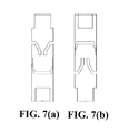
- FIG. 7( a ) is a top view of a flexible hinge
- FIG. 7( b ) is a left view of FIG. 7( a ) ;
- FIG. 8( a ) is a schematic diagram of the principle of the traditional passive vibration isolation mechanism
- FIG. 8( b ) is a schematic diagram of the principle of a vibration isolation mechanism of the present invention.
- FIG. 9 is a comparative diagram of a curve of the traditional passive vibration isolation unit in FIG. 1 vs. transmissibility of the present invention in situations of an open loop and a closed loop;
- FIG. 10 is a schematic diagram of positional relations between axes of the six sets of single-degree-of-freedom active and passive composite vibration isolation devices in FIG. 1 .
- a Cartesian space rectangular coordinate system is employed as the coordinate system of the load platform, the centroid of the load platform is the origin O, the load platform is located in an XOY plane, the X axis and the Z axis are coplanar in the principal plane, the horizontal leftward direction of the X axis is the positive direction, the vertical upward direction of the Z axis is the positive direction, and the outward direction of the Y axis perpendicular to the principal plane is the positive direction.
- a unit direction vector of a single-degree-of-freedom active and passive composite vibration isolation device refers to a ratio of a vector from a connecting point B between the lower flexible hinge in the single-degree-of-freedom active and passive composite vibration isolation device and the basic platform to a connecting point A between the upper flexible hinge and the load platform to the modulus of the vector, which may be expressed as:
- a platform radius vector is a vector formed by hinge connecting points of the centroid point of the load platform to the upper flexible hinge of the single-degree-of-freedom active and passive composite vibration isolation device and the load platform.
- the present invention includes a basic platform 10 , a load platform 20 , six sets of single-degree-of-freedom active and passive composite vibration isolation devices 30 that are exactly the same and a controller 40 .
- Upper and lower ends of each set of single-degree-of-freedom active and passive composite vibration isolation devices are connected with the load platform 20 and the basic platform 10 by sunk screws, respectively.
- Positional relations between axes of the six sets of single-degree-of-freedom active and passive composite vibration isolation devices form six sides of a cube, and intersection points of the axes are six vertices of the cube.
- the positional relations between axes of the six sets of single-degree-of-freedom active and passive composite vibration isolation devices are as the solid lines in the figure, and there are a total of six solid lines.
- the cube has twelve sides in total, diagonal vertices A and B are two endpoints of one diagonal line of the cube, and after three sides connected by the two diagonal vertices A and B respectively are removed, that is, six dashed lines in the figure are removed, the remaining six solid lines are spatial arrangements of six axes of the six sets of single-degree-of-freedom active and passive composite vibration isolation devices. Referring to FIG. 1 and FIG.
- three upper intersection points determine the plane of the load platform 20 and are evenly distributed on the load platform 20 along the circumference at an interval of 120°; three lower intersection points determine the basic platform 10 and are evenly distributed on the basic platform 10 along the circumference at an interval of 120°; and two adjacent axes are perpendicular to each other.
- each set of single-degree-of-freedom active and passive composite vibration isolation device 30 consists of a metal spring 31 , a lower guide plate 32 , an upper guide plate 33 , a sleeve 34 , a piezoelectric actuator 351 , a mechanical amplification member 352 , a dynamic force sensor 353 , a bellow shielding tube 354 , a baffle plate 355 , a lower flexible hinge 36 and an upper flexible hinge 37 .
- the piezoelectric actuator 351 is mounted in the mechanical amplification member 352 , the right end of the mechanical amplification member 352 is connected with the baffle plate 355 and the upper guide plate 33 by an upper guide bolt 331 , the left end of the mechanical amplification member 352 is connected with the right end of the dynamic force sensor 353 by a bolt, and the left end of the dynamic force sensor 353 is connected with the upper flexible hinge 37 by transfer.
- the lower guide plate 32 is connected with the lower flexible hinge 36 by a lower guide bolt 321 , the sleeve 34 is assembled between the lower guide plate 32 and the upper guide plate 33 , and the metal spring 31 is sleeved outside the sleeve 34 and is in contact with the lower guide plate 32 and the upper guide plate 33 .
- the upper guide bolt 331 and the lower guide bolt 321 are inserted into a left orifice and a right orifice of the sleeve 34 , respectively, and are in sliding fit with the sleeve 34 .
- An end portion of the lower flexible hinge 36 and an end portion of the upper flexible hinge 37 are connected with the basic platform 10 and the load platform 20 through sunk screws, respectively.
- the piezoelectric actuator 351 and the dynamic force sensor 353 are connected with the controller 40 by wires, respectively.
- the dynamic force sensor detects a vibration signal of the load platform, and inputs the vibration signal to the controller 40 .
- the controller obtains a real-time control signal by calculation, and outputs the real-time control signal to the piezoelectric actuator 351 .
- the mechanical amplification member 352 mechanically amplifies the stroke of the piezoelectric actuator 351 , and acts on the load platform 20 , to make active control compensations for residual error vibrations of the load platform 20 .
- the metal spring 31 , the lower guide plate 32 , the lower guide bolt 321 , the upper guide plate 33 , the upper guide bolt 331 and the sleeve 34 make up a passive vibration isolation unit.
- the piezoelectric actuator 351 , the mechanical amplification member 352 , the dynamic force sensor 353 , the bellow shielding tube 354 , the baffle plate 355 and the controller 40 form a closed-loop active vibration isolation unit.
- the basic platform 10 may be in a shape of a centrally hollow ring, an equilateral triangle ring or a rectangular ring, so as to be lightweight on the premise of ensuring structural stiffness and strength.
- the load platform 20 may be a circular plate or a rectangular plate, so as to ensure the load mounting space.
- the lower flexible hinge 36 and the upper flexible hinge 37 are of the same structure and both employ a flexible Hooke joint.
- they are double-axis flexible hinges, equivalent to a combination of two revolute pairs whose axes intersect at one point, the members are allowed to have two degrees of freedom of relative rotation, and the intersection point of two axes is the hinge point of the hinges, for avoiding clearance and friction and ensuring high axial stiffness and low rotational stiffness.
- the piezoelectric actuator 351 is a stack-type piezoelectric ceramic actuator.
- the mechanical amplification member 352 is a triangular amplification member.
- a triangular amplification actuator with the model of P06.X60AK manufactured by Harbin Core Today Science & Technology Co., Ltd. is employed, including a mechanical amplification member and a piezoelectric actuator.
- control method of the present invention includes calculating a logical axis signal, calculating a logical axis control signal, calculating physical axis real-time control signals and a transfer step.
- J is the velocity Jacobian matrix
- x, y, z, ⁇ , ⁇ , ⁇ are translational displacement signals and rotation angle signals of the centroid point of the load platform along X, Y and Z axes, respectively;
- the active control algorithm is a proportional integral (PI) force feedback control algorithm, a recursive least square (RLS) adaptive algorithm or a least mean square (LMS) adaptive control algorithm.
- PI proportional integral
- RLS recursive least square
- LMS least mean square
- PI force feedback control algorithm is derived from Classical Control Theory, Proportional-Integral-Differential (PID) Controller; see the book Parameter Setting and Implementation of the PID Controller , written by Huang Yourui, Qu Liguo, Beijing: Science Press, 2010.
- the recursive least square (RLS) adaptive algorithm and the least mean square (LMS) adaptive control algorithm are both derived from the book Adaptive Filtering Algorithm and Implementation , Written by Paulo S. R. Diniz, Beijing: Publishing House of Electronics Industry, 2014; and Adaptive Signal Processing Technology , written by Zhao Chunhui, Zhang Chaozhu, et al., Beijing: Beijing Institute of Technology Press, 2009.
- J T [ l 1 T l 2 T l 3 T l 4 T l 5 T l 6 T l 1 T ⁇ p ⁇ 1 l 2 T ⁇ p ⁇ 2 l 3 T ⁇ p ⁇ 3 l 4 T ⁇ p ⁇ 4 l 5 T ⁇ p ⁇ 5 l 6 T ⁇ p ⁇ 6 ]
- control signals of the six sets of single-degree-of-freedom active and passive composite vibration isolation devices are transferred to the corresponding piezoelectric actuators, respectively, to drive the mechanical amplification mechanism to make real-time active vibration control over the corresponding single-degree-of-freedom active and passive composite vibration isolation devices.
- x′, y′, z′, ⁇ ′, ⁇ ′, ⁇ ′ are translational displacement signals and rotation angle signals of the centroid point, after a calculation process, along X, Y and Z axes, respectively.
- u(t) is a time-domain output signal of a proportional integral (PI) control algorithm
- k p is a proportional gain coefficient
- k i is an integral gain coefficient
- e(t) is an error of x′ and x
- t is a time coefficient.
- the passive vibration isolation mechanism in the prior art is formed by the traditional spring-mass-damping units, to achieve simple passive vibration isolation, and the transmissibility curve function G thereof is:
- x 1 is the vibration displacement amount of the load platform
- x 0 is the vibration displacement amount of the basic platform
- C is the equivalent damping of the mechanism
- K is the equivalent stiffness between the load platform and the basic platform
- M is the mass of the load platform
- ⁇ is a frequency domain coefficient.
- a passive elastic element (a metal spring is employed in the embodiment) of which the stiffness is easy to change is added in series, and an active feedback control loop is added.
- the active feedback control loop runs in a mode that the sensor feeds back, the controller calculates and the actuator outputs, to form an active and passive composite vibration isolation mechanism, and the transmissibility curve function G o thereof in the situation of an open loop is:
- x 2 is the vibration displacement mount of the load platform when the active and passive composite vibration isolation mechanism is employed
- K 0 is the stiffness of the spring added in series
- K is the equivalent stiffness of the original system
- C is the equivalent damping of the original system
- M is the mass of the load platform.
- the passive vibration isolation unit is actively controlled (a PI force feedback control algorithm is employed in this embodiment) with the vibration signal on the load platform as a reference, to form an active and passive composite vibration isolation unit, wherein the control force F is:
- k p is a proportional gain coefficient
- k i is an integral gain coefficient
- e(t) is an error between the logical axis control signal and the logical axis displacement signal
- t is a time coefficient
- ⁇ is a frequency domain coefficient
- the transmissibility curve function G c of the active and passive composite vibration isolation mechanism in the situation of a closed loop is:
- FIG. 9 is a curve of the existing passive vibration isolation mechanism in FIG. 8 vs. transmissibility of the present invention in situations of a closed loop and an open loop. It can be seen from the solid lines in the figure that, when the existing passive vibration isolation mechanism is employed, the passive transmissibility thereof has a higher peak value at the low frequency formant, and the natural frequency of the system is higher. It can be seen from the dashed line in the figure that, after the structure of the present invention is employed, as an additional stiffness spring is connected in series, the stiffness of the system is further reduced, and the damping is also further enhanced.
- the single-degree-of-freedom active and passive composite vibration isolation device is composed of active and passive vibration isolation units, and the metal spring, the lower guide plate, the lower guide bolt, the upper guide plate, the upper guide bolt and the sleeve make up the passive vibration isolation unit; the piezoelectric actuator, the mechanical amplification member, the dynamic force sensor, the bellow shielding tube, the baffle plate and the controller form a closed-loop active vibration isolation unit.
- the metal spring having different stiffness and made of different materials can be replaced according to actual requirements to achieve the property of variable stiffness, so as to change the effective bandwidth of the system and adapt to different micro vibration environments.
- the upper and lower guide plates serve as a guide mechanism to ensure the axial motion precision of the metal spring, and the sleeve, as a stroke protection mechanism avoids that the passive vibration isolation unit is plastically deformed during motion and transportation.
- the dynamic force sensor has the characteristic of higher SNR relative to the acceleration sensor, for detecting a dynamic real-time vibration signal of the load platform and inputting the measured vibration signal to the controller.
- a physical axis real-time control signal is calculated by an active control algorithm and is output to the piezoelectric actuator.
- the piezoelectric actuator as an output mechanism of active real-time control, has characteristics such as low power consumption, high positioning precision and rapid frequency response, which not only can effectively suppress and isolate micro vibrations, but also expands and extends, with its low power consumption, application environments (e.g., precise vibration reduction of space remote sensing satellites) in which energy consumption is relatively limited.
- the mechanical amplification member mechanically amplifies the stroke of the piezoelectric actuator, to widen its effective working stroke, and makes the piezoelectric actuator act on the load platform, to make active control compensations for residual error vibrations of the load platform, thus reducing vibrations of the load platform and achieving the effect of vibration suppression.
- the proportional integral (PI) force feedback control algorithm is simple and mature and has a small calculation amount, the feedback control structure is simple and easy to implement, and an effect of skyhook damping is achieved, thus effectively attenuating the formant at the natural frequency.
- the present invention has a simple structure, is adjustable in stiffness, and may reduce dynamic stiffness of the system by using series connection of system stiffness, thus reducing the natural frequency of the system.
- the present invention can change the system stiffness and damping characteristics by using the active vibration isolation unit, thus changing the property of transmissibility of the system, and can suppress and isolate six-degree-of-freedom micro vibrations in translational directions and rotational directions of X, Y and Z axes, which not only better attenuates high-frequency signals but also, in the control method, can increase the skyhook damping of formant frequency points and can effectively suppress low-frequency resonance and isolate low-frequency vibrations.
- the present invention can adapt to different occasions, and can effectively attenuate micro vibrations at different frequency bands, to provide reliable guarantee for precise machining and measurement devices in micro vibration environments.
Abstract
A six-degree-of-freedom micro vibration suppression platform includes a basic platform, a load platform, six sets of single-degree-of-freedom active and passive composite vibration isolation devices that are exactly the same and a controller. Upper and lower ends of each set of single-degree-of-freedom active and passive composite vibration isolation devices are connected with the load platform and the basic platform, respectively. A control method includes: calculating a logical axis signal, calculating a logical axis control signal, calculating physical axis real-time control signals and a transfer step.
Description
The present invention belongs to the field of micro vibration isolation and suppression, and in particular, relates to a six-degree-of-freedom micro vibration suppression platform and a control method thereof.
Micro vibrations are present in some complicated working environments, and the micro vibrations are key factors that affect machining or working precision of devices. The traditional passive vibration isolator consists of mass-spring-damping elements, but it cannot meet the vibration isolation requirement of precise machining as it has inherent contradictions between the low-frequency vibration transmissibility and the high-frequency vibration attenuation rate. Relative to a passive vibration isolation mechanism, active vibration isolation has greatly improved the performance of the system, but it requires a sensor-actuator pair and a corresponding active control system, which requires the active vibration isolation mechanism to have a simple structure, an efficient algorithm and lower power consumption.
In terms of the structure, the current mainstream micro vibration isolation or suppression devices are formed by connecting passive vibration isolation elements and active actuators in a certain manner. For example, means such as the active and passive composite use of an air spring and a voice coil motor, the active and passive composite use of a diaphragm spring and a voice coil motor, the active and passive composite use of a metal spring and a linear motor, effectively suppress the micro vibrations and have better low frequency and high frequency attenuation capability, but they all have the following problems:
1. Although the active and passive parallel mechanism of the air spring and the voice coil spring causes the vibration isolator to have the advantages of large stroke, high load, low natural frequency and so on, it has a complicated structure and needs to supply air continuously, and the voice coil motor has great power consumption, all of which are not conductive to applications in the space and thus restrict its application to the micro vibration suppression.
2. The active and passive parallel mechanism of the metal spring and the linear motor intends to obtain a lower natural frequency by using a compression spring, which has a higher requirement for the mounting precision and is also relatively difficult in enhancing the control precision.
3. An active vibration isolator designed and applied by employing piezoelectric ceramics as an actuating mechanism has the advantages of high frequency response, high positioning precision and long service life, but it also has the disadvantage of a smaller actuation stroke. Therefore, in practical use, it is often necessary to broaden its effective stroke in combination with technical means, leading to the increase in the cost and inconvenient use.
4. For the field of micro vibration suppression and isolation, wide frequency band and high frequency response are its main characteristics, and the piezoelectric actuator stands out. However, as the active vibration isolation mechanism that employs piezoelectric ceramics as an actuator has greater structural stiffness, it is mostly referred to as a “hard” structure. As a result, the natural frequency of the system is too high, and it is difficult to effectively suppress low-frequency vibrations.
The Patent Document CN102168738B recorded in the State Intellectual Property Patent Office of China discloses a six-degree-of-freedom active and passive dynamic vibration absorbing device, which consists of six motor-actuated single-degree-of-freedom dynamic vibration absorbers, has active and passive control modes and can adapt to multi-degree-of-freedom complicated vibration suppression working conditions, but has special mounting requirements for occasions of use. Moreover, the motion of each degree of freedom requires two vibration absorbers to act at the same time, the requirement for synchronous control precision is higher, and the manufacturing difficulty and the use restriction are greater.
The present invention provides a six-degree-of-freedom micro vibration suppression platform and also provides a control method thereof, to solve the problems in the prior art that the active and passive composite vibration isolation mechanism is of a complicated structure and is controlled in a complicated way.
In order to achieve the above objective, the present invention provides a six-degree-of-freedom micro vibration suppression platform, including: a basic platform, a load platform, six sets of single-degree-of-freedom active and passive composite vibration isolation devices that are exactly the same and a controller;
axes of the six sets of single-degree-of-freedom active and passive composite vibration isolation devices forming six sides remaining after the sides connected by two diagonal vertices of a cube are removed, intersection points of the axes being six vertices of the cube, three upper intersection points being fixed onto the load platform and being evenly distributed on the load platform along the circumference at an interval of 120°; three lower intersection points being fixed onto the basic platform and being evenly distributed on the basic platform along the circumference at an interval of 120°; axes of any two adjacent single-degree-of-freedom active and passive composite vibration isolation devices being perpendicular to each other, and the same end being disposed towards the intersection point of the axes;
the single-degree-of-freedom active and passive composite vibration isolation devices each including an upper flexible hinge, an active vibration isolation assembly, a passive vibration isolation assembly and a lower flexible hinge that are sequentially connected and fixed; and
the controller being connected with the active vibration isolation assemblies of the six sets of single-degree-of-freedom active and passive composite vibration isolation devices, for obtaining a real-time control signal by calculation and outputting the real-time control signal to the active vibration isolation assemblies, to make active control compensations for vibrations.
Further, the active vibration isolation assembly includes a piezoelectric actuator, a mechanical amplification member, a dynamic force sensor, a bellow shielding tube and a baffle plate; and
the passive vibration isolation assembly includes a metal spring, an upper guide plate, a lower guide plate, a sleeve and a screw;
wherein
the piezoelectric actuator, the mechanical amplification member and the dynamic force sensor are disposed in the interior of the bellow shielding tube, and at a lower end of the bellow shielding tube is the baffle plate; the dynamic force sensor is fixed to an upper end of the bellow shielding tube, an upper end of the mechanical amplification member is fixed to a lower end of the dynamic force sensor, and a lower end of the mechanical amplification member is stopped at an inner side of the baffle plate and is fixed to an upper end of the screw; the piezoelectric actuator is fixed to the interior of the mechanical amplification member, and the mechanical amplification member is used for amplifying the motion stroke of the piezoelectric actuator; the bellow shielding tube is axially telescopic; and the upper flexible hinge is mounted to the upper end of the bellow shielding tube;
the upper end of the screw is an upper guide bolt, and the lower end thereof is a lower guide bolt; the upper guide bolt passes through the baffle plate to enter the interior of the bellow shielding tube, and is connected and fixed to the lower end of the mechanical amplification member; the upper guide plate is stopped at a lower side of the baffle plate, and is fixed by the upper guide bolt; an end portion of the lower guide bolt is fixed to an upper end of the lower flexible hinge, and the lower guide plate is stopped at the upper end of the lower flexible hinge and is fixed by the lower guide bolt; the metal spring is sleeved on the screw and is stopped between the upper guide plate and the lower guide plate, and the sleeve is sleeved between the screw and the metal spring; and
the piezoelectric actuator and the dynamic force sensor are connected with the controller, respectively, and the dynamic force sensor is used for detecting a vibration signal of the load platform and inputting the vibration signal to the controller; the controller is used for calculating a real-time control signal according to the obtained vibration signal and outputting the real-time control signal to the piezoelectric actuator, to deform the piezoelectric actuator; the mechanical amplification member is used for mechanically amplifying the stroke of the piezoelectric actuator, and acting on the load platform by transfer of the bellow shielding tube and the upper flexible hinge, to make active control compensations for residual error vibrations of the load platform.
Further, the lower flexible hinge and the upper flexible hinge are of the same structure and both employ a flexible Hooke joint.
Further, the piezoelectric actuator is a stack-type or tube-type piezoelectric ceramic actuator; the mechanical amplification member is a triangular amplification member or a micro motion worktable amplification member.
Further, the method includes the following steps:
A. calculating a logical axis displacement signal x of the centroid point of the load platform
the six active vibration isolation assemblies measuring vibration force signals in axial directions of the six sets of single-degree-of-freedom active and passive composite vibration isolation devices respectively and delivering up the vibration force signals to the controller, the controller converting the vibration force signals to displacement signals q1, q2, q3, q4, q5, q6, by two integrations and a detrend item, to form a physical axis displacement signal q=[q1 q2 q3 q4 q5 q6]T which is converted, by an operation {dot over (q)}=J·{dot over (x)} to the logical axis displacement signal of the centroid point of the load platform as follows:
x=[xyzαβγ] T
x=[xyzαβγ] T
wherein J is the velocity Jacobian matrix, and x, y, z, α, β, γ are translational displacement signals and rotation angle signals of the centroid point of the load platform along X, Y and Z axes, respectively;
wherein l1, l2, l3, l4, l5, l6 are unit direction vectors of the six sets of single-degree-of-freedom active and passive composite vibration isolation devices, respectively, p1, p2, p3, p4, p5, p6 are platform radius vectors formed by hinge connecting points of the upper flexible hinges of the six sets of single-degree-of-freedom to active and passive composite vibration isolation devices and the centroid point of the load platform, respectively, p=[p1 p2 p3 p4 p5 p6] is a radius matrix formed by the platform radius vectors, and {tilde over (p)}=[{tilde over (p)}1 {tilde over (p)}2 {tilde over (p)}3 {tilde over (p)}4 {tilde over (p)}5 {tilde over (p)}6] is an anti-symmetric matrix of p=[p1 p2 p3 p4 p5 p6];
B. calculating a logical axis control signal x′ of the centroid point of the load platform
obtaining a logical axis control signal by x′=[x′ y′ z′ α′ β′ γ′]T calculation with an active control algorithm according to the logical axis displacement signal x, wherein x′, y′, z′, α′, β′, γ′ are translational displacement signals and rotation angle signals of the centroid point, after a calculation process, along X, Y and Z axes, respectively;
C. calculating physical axis real-time control signals of the six sets of single-degree-of-freedom active and passive composite vibration isolation devices:
by transposing the velocity Jacobian matrix JT converting the logical axis control signal x′ to a physical axis control signal q′=[q′1 q′2 q′3 q′4 q′5 q′6]T, {dot over (q)}=JT·{dot over (x)}′, wherein q′1, q′2, q′3, q′4, q′5, q′6 are respectively control signals of the six sets of single-degree-of-freedom active and passive composite vibration isolation devices after the conversion; wherein the expression of transposing the Jacobian matrix JT is as follows:
D. a transfer step:
the controller transferring the physical axis real-time control signals of the six sets of single-degree-of-freedom active and passive composite vibration isolation devices to the corresponding active vibration isolation assemblies, respectively, to make real-time active vibration compensations for the corresponding single-degree-of-freedom active and passive composite vibration isolation devices.
Further, the active vibration isolation assemblies each include a piezoelectric actuator, a mechanical amplification member and a dynamic force sensor, and in step A, the six dynamic force sensors measure vibration force signals in axial directions of the six sets of single-degree-of-freedom active and passive composite vibration isolation devices, respectively; in step D, the controller transfer the physical axis real-time control signals of the six sets of single-degree-of-freedom active and passive composite vibration isolation devices to the corresponding piezoelectric actuators, respectively; the mechanical amplification members amplify the motion strokes of the piezoelectric actuators to make vibration compensations, thereby achieving active vibration compensations.
The present invention has a simple structure, is adjustable in stiffness, and may reduce dynamic stiffness of the system by using series connection of system stiffness, thus reducing the natural frequency of the system. The present invention can change the system stiffness and damping characteristics by using the active vibration isolation unit, thus changing the property of transmissibility of the system, and can suppress and isolate six-degree-of-freedom micro vibrations in translational directions and rotational directions of X, Y and Z axes, which not only better attenuates high-frequency signals but also, in the control method, can increase the skyhook damping of formant frequency points and can effectively suppress low-frequency resonance and isolate low-frequency vibrations. The present invention can adapt to different occasions, and can effectively attenuate micro vibrations at different frequency bands, to provide reliable guarantee for precise machining and measurement devices in micro vibration environments.
In all the drawings, the same reference signs are used to represent the same elements or structures, wherein
| |
|
|
| single-degree-of-freedom active and passive composite |
| |
| |
|
|
| |
|
|
| piezoelectric | mechanical amplification | |
| actuator | ||
| 351 | member 352 | sensor 353 |
| bellow shielding | |
lower |
| tube | ||
| 354 | |
|
| upper |
||
In order to make the objectives, technical solutions and advantages of the present invention more comprehensible, the present invention is further described below in detail with reference to the accompanying drawings and embodiments. It should be understood that specific embodiments described herein are merely used to explain the present invention instead of being used to limiting the present invention. In addition, technical features involved in various implementation modes of the present invention described in the following can be combined with each other as long as they do not conflict with each other.
To understand the present invention more clearly, the concepts and terms involved in the present invention are explained in the following:
In the present invention, a Cartesian space rectangular coordinate system is employed as the coordinate system of the load platform, the centroid of the load platform is the origin O, the load platform is located in an XOY plane, the X axis and the Z axis are coplanar in the principal plane, the horizontal leftward direction of the X axis is the positive direction, the vertical upward direction of the Z axis is the positive direction, and the outward direction of the Y axis perpendicular to the principal plane is the positive direction.
A unit direction vector of a single-degree-of-freedom active and passive composite vibration isolation device refers to a ratio of a vector from a connecting point B between the lower flexible hinge in the single-degree-of-freedom active and passive composite vibration isolation device and the basic platform to a connecting point A between the upper flexible hinge and the load platform to the modulus of the vector, which may be expressed as:
A platform radius vector is a vector formed by hinge connecting points of the centroid point of the load platform to the upper flexible hinge of the single-degree-of-freedom active and passive composite vibration isolation device and the load platform.
The present invention is further described below with reference to the accompanying drawing and embodiments.
As shown in FIG. 1 to FIG. 4 , the present invention includes a basic platform 10, a load platform 20, six sets of single-degree-of-freedom active and passive composite vibration isolation devices 30 that are exactly the same and a controller 40. Upper and lower ends of each set of single-degree-of-freedom active and passive composite vibration isolation devices are connected with the load platform 20 and the basic platform 10 by sunk screws, respectively.
Positional relations between axes of the six sets of single-degree-of-freedom active and passive composite vibration isolation devices form six sides of a cube, and intersection points of the axes are six vertices of the cube. Specifically, as shown in FIG. 10 , the positional relations between axes of the six sets of single-degree-of-freedom active and passive composite vibration isolation devices are as the solid lines in the figure, and there are a total of six solid lines. Suppose that there is a cube in the space, the cube has twelve sides in total, diagonal vertices A and B are two endpoints of one diagonal line of the cube, and after three sides connected by the two diagonal vertices A and B respectively are removed, that is, six dashed lines in the figure are removed, the remaining six solid lines are spatial arrangements of six axes of the six sets of single-degree-of-freedom active and passive composite vibration isolation devices. Referring to FIG. 1 and FIG. 10 , three upper intersection points determine the plane of the load platform 20 and are evenly distributed on the load platform 20 along the circumference at an interval of 120°; three lower intersection points determine the basic platform 10 and are evenly distributed on the basic platform 10 along the circumference at an interval of 120°; and two adjacent axes are perpendicular to each other.
As shown in FIG. 5 and FIG. 6 , each set of single-degree-of-freedom active and passive composite vibration isolation device 30 consists of a metal spring 31, a lower guide plate 32, an upper guide plate 33, a sleeve 34, a piezoelectric actuator 351, a mechanical amplification member 352, a dynamic force sensor 353, a bellow shielding tube 354, a baffle plate 355, a lower flexible hinge 36 and an upper flexible hinge 37.
The piezoelectric actuator 351 is mounted in the mechanical amplification member 352, the right end of the mechanical amplification member 352 is connected with the baffle plate 355 and the upper guide plate 33 by an upper guide bolt 331, the left end of the mechanical amplification member 352 is connected with the right end of the dynamic force sensor 353 by a bolt, and the left end of the dynamic force sensor 353 is connected with the upper flexible hinge 37 by transfer.
The lower guide plate 32 is connected with the lower flexible hinge 36 by a lower guide bolt 321, the sleeve 34 is assembled between the lower guide plate 32 and the upper guide plate 33, and the metal spring 31 is sleeved outside the sleeve 34 and is in contact with the lower guide plate 32 and the upper guide plate 33. The upper guide bolt 331 and the lower guide bolt 321 are inserted into a left orifice and a right orifice of the sleeve 34, respectively, and are in sliding fit with the sleeve 34.
An end portion of the lower flexible hinge 36 and an end portion of the upper flexible hinge 37 are connected with the basic platform 10 and the load platform 20 through sunk screws, respectively.
The piezoelectric actuator 351 and the dynamic force sensor 353 are connected with the controller 40 by wires, respectively. The dynamic force sensor detects a vibration signal of the load platform, and inputs the vibration signal to the controller 40. The controller obtains a real-time control signal by calculation, and outputs the real-time control signal to the piezoelectric actuator 351. The mechanical amplification member 352 mechanically amplifies the stroke of the piezoelectric actuator 351, and acts on the load platform 20, to make active control compensations for residual error vibrations of the load platform 20.
The metal spring 31, the lower guide plate 32, the lower guide bolt 321, the upper guide plate 33, the upper guide bolt 331 and the sleeve 34 make up a passive vibration isolation unit.
The piezoelectric actuator 351, the mechanical amplification member 352, the dynamic force sensor 353, the bellow shielding tube 354, the baffle plate 355 and the controller 40 form a closed-loop active vibration isolation unit.
The basic platform 10 may be in a shape of a centrally hollow ring, an equilateral triangle ring or a rectangular ring, so as to be lightweight on the premise of ensuring structural stiffness and strength.
The load platform 20 may be a circular plate or a rectangular plate, so as to ensure the load mounting space.
As an embodiment, the lower flexible hinge 36 and the upper flexible hinge 37 are of the same structure and both employ a flexible Hooke joint. As shown in FIG. 7(a) and FIG. 7(b) , they are double-axis flexible hinges, equivalent to a combination of two revolute pairs whose axes intersect at one point, the members are allowed to have two degrees of freedom of relative rotation, and the intersection point of two axes is the hinge point of the hinges, for avoiding clearance and friction and ensuring high axial stiffness and low rotational stiffness.
In this embodiment, the piezoelectric actuator 351 is a stack-type piezoelectric ceramic actuator. The mechanical amplification member 352 is a triangular amplification member. A triangular amplification actuator with the model of P06.X60AK manufactured by Harbin Core Tomorrow Science & Technology Co., Ltd. is employed, including a mechanical amplification member and a piezoelectric actuator.
As an embodiment, the control method of the present invention includes calculating a logical axis signal, calculating a logical axis control signal, calculating physical axis real-time control signals and a transfer step.
A. a step of calculating a logical axis displacement signal x:
Six dynamic force sensors measure vibration force signals in axial directions of the six sets of single-degree-of-freedom active and passive composite vibration isolation devices, respectively, and the vibration force signals are converted to displacement signals q1, q2, q3, q4, q5, q6, by two integrations and a detrend item, to form a physical axis displacement signal q=[q1 q2 q3 q4 q5 q6]T which is converted, by an operation {dot over (q)}=J·{dot over (x)}, to the logical axis displacement signal of the centroid point of the load platform as follows:
x=[xyzαβγ] T
x=[xyzαβγ] T
wherein J is the velocity Jacobian matrix, and x, y, z, α, β, γ are translational displacement signals and rotation angle signals of the centroid point of the load platform along X, Y and Z axes, respectively;
wherein l1, l2, l3, l4, l5, l6 are unit direction vectors of the six sets of single-degree-of-freedom active and passive composite vibration isolation devices, respectively, p1, p2, p3, p4, p5, p6 re platform radius vectors formed by hinge connecting points of the upper flexible hinges of the six sets of single-degree-of-freedom active and passive composite vibration isolation devices and the centroid point of the load platform, respectively, p=[p1 p2 p3 p4 p5 p6] is a radius matrix formed by the platform radius vectors, and {tilde over (p)}=[{tilde over (p)}1 {tilde over (p)}2 {tilde over (p)}3 {tilde over (p)}4 {tilde over (p)}5 {tilde over (p)}6] is an anti-symmetric matrix of p=[p1 p2 p3 p4 p5 p6].
B. a step of calculating a logical axis control signal:
a logical axis control signal x′=[x′ y′ z′ α′ β′ γ′]T is obtained by calculation with an active control algorithm according to the logical axis displacement signal x, wherein x′, y′, z′, α′, β′, γ′ are translational displacement signals and rotation angle signals of the centroid point, after a calculation process, along X, Y and Z axes, respectively.
In the step of calculating a logical axis control signal, the active control algorithm is a proportional integral (PI) force feedback control algorithm, a recursive least square (RLS) adaptive algorithm or a least mean square (LMS) adaptive control algorithm.
The proportional integral (PI) force feedback control algorithm is derived from Classical Control Theory, Proportional-Integral-Differential (PID) Controller; see the book Parameter Setting and Implementation of the PID Controller, written by Huang Yourui, Qu Liguo, Beijing: Science Press, 2010.
The recursive least square (RLS) adaptive algorithm and the least mean square (LMS) adaptive control algorithm are both derived from the book Adaptive Filtering Algorithm and Implementation, Written by Paulo S. R. Diniz, Beijing: Publishing House of Electronics Industry, 2014; and Adaptive Signal Processing Technology, written by Zhao Chunhui, Zhang Chaozhu, et al., Beijing: Beijing Institute of Technology Press, 2009.
C. a step of calculating physical axis real-time control signals:
by transposing the velocity Jacobian matrix JT, the logical axis control signal x′ is converted to a physical axis control signal q′=[q′1 q′2 q′3 q′4 q′5 q′6]T, {dot over (q)}=JT·{dot over (x)}′, wherein q′1, q′2, q′3, q′4, q′5, q′6 are respectively control signals of the six sets of single-degree-of-freedom active and passive composite vibration isolation devices after the conversion; wherein the expression of transposing the Jacobian matrix JT is as follows:
D. a transfer step:
the control signals of the six sets of single-degree-of-freedom active and passive composite vibration isolation devices are transferred to the corresponding piezoelectric actuators, respectively, to drive the mechanical amplification mechanism to make real-time active vibration control over the corresponding single-degree-of-freedom active and passive composite vibration isolation devices.
In the step of calculating a logical axis control signal, a calculation process is performed on the logical axis displacement signal x=[x,y,z] by a proportional integral (PI) force feedback control algorithm to obtain a logical axis control signal
x′=[x′y′z′α′β′γ′] T,
x′=[x′y′z′α′β′γ′] T,
wherein x′, y′, z′, α′, β′, γ′ are translational displacement signals and rotation angle signals of the centroid point, after a calculation process, along X, Y and Z axes, respectively.
The proportional integral (PI) force feedback control algorithm is:
x′=x·u(t), u(t)=k p +k i ∫e(t)dt,
x′=x·u(t), u(t)=k p +k i ∫e(t)dt,
in the formula, u(t) is a time-domain output signal of a proportional integral (PI) control algorithm, kp is a proportional gain coefficient, ki is an integral gain coefficient, e(t) is an error of x′ and x, and t is a time coefficient.
Vibration isolation principles of the passive vibration isolation mechanism in the present invention and in the prior art are compared in the following:
As shown in FIG. 8(a) , the passive vibration isolation mechanism in the prior art is formed by the traditional spring-mass-damping units, to achieve simple passive vibration isolation, and the transmissibility curve function G thereof is:
in the formula, x1 is the vibration displacement amount of the load platform, x0 is the vibration displacement amount of the basic platform, C is the equivalent damping of the mechanism, K is the equivalent stiffness between the load platform and the basic platform, M is the mass of the load platform, s=jω is a complex variable of Laplace transform, and ω is a frequency domain coefficient.
As shown in FIG. 8(b) , on the basis of the passive vibration isolation mechanism in the prior art, in the present invention, a passive elastic element (a metal spring is employed in the embodiment) of which the stiffness is easy to change is added in series, and an active feedback control loop is added. The active feedback control loop runs in a mode that the sensor feeds back, the controller calculates and the actuator outputs, to form an active and passive composite vibration isolation mechanism, and the transmissibility curve function Go thereof in the situation of an open loop is:
in the formula, x2 is the vibration displacement mount of the load platform when the active and passive composite vibration isolation mechanism is employed, K0 is the stiffness of the spring added in series, K is the equivalent stiffness of the original system, C is the equivalent damping of the original system, and M is the mass of the load platform. The passive vibration isolation unit is actively controlled (a PI force feedback control algorithm is employed in this embodiment) with the vibration signal on the load platform as a reference, to form an active and passive composite vibration isolation unit, wherein the control force F is:
wherein a time domain formula of the proportional integral (PI) control algorithm is:
u(t)=k p +k i ∫e(t)dt,
u(t)=k p +k i ∫e(t)dt,
a frequency domain formula of the proportional integral (PI) control algorithm is:
G=k p +k i1/s,
G=k p +k i1/s,
in the above formulas, kp is a proportional gain coefficient, ki is an integral gain coefficient, e(t) is an error between the logical axis control signal and the logical axis displacement signal, t is a time coefficient, s=jω is a complex variable of Laplace transform, and ω is a frequency domain coefficient.
The transmissibility curve function Gc of the active and passive composite vibration isolation mechanism in the situation of a closed loop is:
In the present invention, the single-degree-of-freedom active and passive composite vibration isolation device is composed of active and passive vibration isolation units, and the metal spring, the lower guide plate, the lower guide bolt, the upper guide plate, the upper guide bolt and the sleeve make up the passive vibration isolation unit; the piezoelectric actuator, the mechanical amplification member, the dynamic force sensor, the bellow shielding tube, the baffle plate and the controller form a closed-loop active vibration isolation unit.
In the passive vibration isolation unit, the metal spring having different stiffness and made of different materials can be replaced according to actual requirements to achieve the property of variable stiffness, so as to change the effective bandwidth of the system and adapt to different micro vibration environments. The upper and lower guide plates serve as a guide mechanism to ensure the axial motion precision of the metal spring, and the sleeve, as a stroke protection mechanism avoids that the passive vibration isolation unit is plastically deformed during motion and transportation.
In the active vibration isolation unit, the dynamic force sensor has the characteristic of higher SNR relative to the acceleration sensor, for detecting a dynamic real-time vibration signal of the load platform and inputting the measured vibration signal to the controller. In the controller, a physical axis real-time control signal is calculated by an active control algorithm and is output to the piezoelectric actuator. The piezoelectric actuator, as an output mechanism of active real-time control, has characteristics such as low power consumption, high positioning precision and rapid frequency response, which not only can effectively suppress and isolate micro vibrations, but also expands and extends, with its low power consumption, application environments (e.g., precise vibration reduction of space remote sensing satellites) in which energy consumption is relatively limited. The mechanical amplification member mechanically amplifies the stroke of the piezoelectric actuator, to widen its effective working stroke, and makes the piezoelectric actuator act on the load platform, to make active control compensations for residual error vibrations of the load platform, thus reducing vibrations of the load platform and achieving the effect of vibration suppression.
In the active control algorithm of the present invention, the proportional integral (PI) force feedback control algorithm is simple and mature and has a small calculation amount, the feedback control structure is simple and easy to implement, and an effect of skyhook damping is achieved, thus effectively attenuating the formant at the natural frequency.
The present invention has a simple structure, is adjustable in stiffness, and may reduce dynamic stiffness of the system by using series connection of system stiffness, thus reducing the natural frequency of the system. The present invention can change the system stiffness and damping characteristics by using the active vibration isolation unit, thus changing the property of transmissibility of the system, and can suppress and isolate six-degree-of-freedom micro vibrations in translational directions and rotational directions of X, Y and Z axes, which not only better attenuates high-frequency signals but also, in the control method, can increase the skyhook damping of formant frequency points and can effectively suppress low-frequency resonance and isolate low-frequency vibrations. The present invention can adapt to different occasions, and can effectively attenuate micro vibrations at different frequency bands, to provide reliable guarantee for precise machining and measurement devices in micro vibration environments.
It will be easily understood by those skilled in the art that the above descriptions are merely preferred embodiments of the present invention but are not used to limit the present invention, and any modification, equivalent replacement, improvement and the like made within the spirit and principle of the present invention should be included in the protection scope of the present invention.
Claims (5)
1. A six-degree-of-freedom micro vibration suppression platform, comprising:
a basic platform, a load platform, six sets of single-degree-of-freedom active and passive composite vibration isolation devices that are exactly the same and a controller;
axes of the six sets of single-degree-of-freedom active and passive composite vibration isolation devices forming six sides remaining after the sides connected by two diagonal vertices of a cube are removed, intersection points of the axes being six vertices of the cube, three upper intersection points being fixed onto the load platform and being evenly distributed on the load platform along the circumference at an interval of 120°; three lower intersection points being fixed onto the basic platform and being evenly distributed on the basic platform along the circumference at an interval of 120°; axes of any two adjacent single-degree-of-freedom active and passive composite vibration isolation devices being perpendicular to each other, and the same end being disposed toward the intersection point of the axes;
the single-degree-of-freedom active and passive composite vibration isolation devices each comprising an upper flexible hinge, an active vibration isolation assembly, a passive vibration isolation assembly and a lower flexible hinge that are sequentially connected and fixed; and
the controller being connected with the active vibration isolation assemblies of the six sets of single-degree-of-freedom active and passive composite vibration isolation devices, for obtaining a real-time control signal by calculation and outputting the real-time control signal to the active vibration isolation assemblies, to make active control compensations for vibrations, and
wherein
the active vibration isolation assembly comprises a piezoelectric actuator, a mechanical amplification member, a dynamic force sensor, a bellow shielding tube and a baffle plate; and
the passive vibration isolation assembly comprises a metal spring, an upper guide plate, a lower guide plate, a sleeve and a screw;
wherein
the piezoelectric actuator, the mechanical amplification member and the dynamic force sensor are disposed in the interior of the bellow shielding tube, and at a lower end of the bellow shielding tube is the baffle plate; the dynamic force sensor is fixed to an upper end of the bellow shielding tube, an upper end of the mechanical amplification member is fixed to a lower end of the dynamic force sensor, and a lower end of the mechanical amplification member is stopped at an inner side of the baffle plate and is fixed to an upper end of the screw; the piezoelectric actuator is fixed to the interior of the mechanical amplification member, and the mechanical amplification member is used for amplifying the motion stroke of the piezoelectric actuator; the bellow shielding tube is axially telescopic; and the upper flexible hinge is mounted to the upper end of the bellow shielding tube;
the upper end of the screw is an upper guide bolt, and the lower end thereof is a lower guide bolt the upper guide bolt passes through the baffle plate to enter the interior of the bellow shielding tube, and is connected and fixed to the lower end of the mechanical amplification member; the upper guide plate is stopped at a lower side of the baffle plate, and is fixed by the upper guide bolt an end portion of the lower guide bolt is fixed to an upper end of the lower flexible hinge, and the lower guide plate is stopped at the upper end of the lower flexible hinge and is fixed by the lower guide bolt the metal spring is sleeved on the screw and is stopped between the upper guide plate and the lower guide plate, and the sleeve is sleeved between the screw and the metal spring; and
the piezoelectric actuator and the dynamic force sensor are connected with the controller, respectively, and the dynamic force sensor is used for detecting a vibration signal of the load platform and inputting the vibration signal to the controller; the controller is used for calculating a real-time control signal according to the obtained vibration signal and outputting the real-time control signal to the piezoelectric actuator, to deform the piezoelectric actuator; the mechanical amplification member is used for mechanically amplifying the stroke of the piezoelectric actuator, and acting on the load platform by transfer of the bellow shielding tube and the upper flexible hinge, to make active control compensations for residual error vibrations of the load platform.
2. The six-degree-of-freedom micro vibration suppression platform according to claim 1 , wherein the lower flexible hinge and the upper flexible hinge are of the same structure and both employ a flexible Hooke joint.
3. The six-degree-of-freedom micro vibration suppression platform according to claim 1 , wherein the piezoelectric actuator is a stack-type or tube-type piezoelectric ceramic actuator; the mechanical amplification member is a triangular amplification member or a micro motion worktable amplification member.
4. A control method of a six-degree-of-freedom micro vibration suppression platform, wherein the six-degree-of-freedom micro vibration suppression platform comprises:
a basic platform, a load platform, six sets of single-degree-of-freedom active and passive composite vibration isolation devices that are exactly the same and a controller;
axes of the six sets of single-degree-of-freedom active and passive composite vibration isolation devices forming six sides remaining after the sides connected by two diagonal vertices of a cube are removed, intersection points of the axes being six vertices of the cube, three upper intersection points being fixed onto the load platform and being evenly distributed on the load platform along the circumference at an interval of 120°; three lower intersection points being fixed onto the basic platform and being evenly distributed on the basic platform along the circumference at an interval of 120°; axes of any two adjacent single-degree-of-freedom active and passive composite vibration isolation devices being perpendicular to each other, and the same end being disposed toward the intersection point of the axes;
the single-degree-of-freedom active and passive composite vibration isolation devices each comprising an upper flexible hinge, an active vibration isolation assembly, a passive vibration isolation assembly and a lower flexible hinge that are sequentially connected and fixed; and
the controller being connected with the active vibration isolation assemblies of the six sets of single-degree-of-freedom active and passive composite vibration isolation devices, for obtaining a real-time control signal by calculation and outputting the real-time control signal to the active vibration isolation assemblies, to make active control compensations for vibrations,
the method comprising:
A. calculating a logical axis displacement signal x of the centroid point of the load platform
the six active vibration isolation assemblies measuring vibration force signals in axial directions of the six sets of single-degree-of-freedom active and passive composite vibration isolation devices respectively and delivering up the vibration force signals to the controller, the controller converting the vibration force signals to displacement signals q1, q2, q3, q4, q5, q6 by two integrations and a detrend item, to form a physical axis displacement signal q=[q1 q2 q3 q4 q5 q6]T which is converted, by an operation {dot over (q)}=J·{dot over (x)}, to the logical axis displacement signal of the centroid point of the load platform as follows:
x=[xyzαβγ] T
x=[xyzαβγ] T
wherein J is the velocity Jacobian matrix, and x, y, z, α, β, γ are translational displacement signals and rotation angle signals of the centroid point of the load platform along X, Y and Z axes, respectively;
wherein l1, l2, l3, l4, l5, l6 are unit direction vectors of the six sets of single-degree-of-freedom active and passive composite vibration isolation devices, respectively, p1, p2, p3, p4, p5, p6 are platform radius vectors formed by hinge connecting points of the upper flexible hinges of the six sets of single-degree-of-freedom active and passive composite vibration isolation devices and the centroid point of the load platform, respectively, p=[p1 p2 p3 p4 p5 p6] is a radius matrix formed by the platform radius vectors, and {tilde over (p)}=[{tilde over (p)}1 {tilde over (p)}2 {tilde over (p)}3 {tilde over (p)}4 {tilde over (p)}5 {tilde over (p)}6] is an anti-symmetric matrix of p=[p1 p2 p3 p4 p5 p6];
B. calculating a logical axis control signal x′ of the centroid point of the load platform
obtaining a logical axis control signal x′=[x′ y′ z′ α′ β′ γ′]T by calculation with an active control algorithm according to the logical axis displacement signal x, wherein x′, y′, z′, α′, β′, γ′ are translational displacement signals and rotation angle signals of the centroid point, after a calculation process, along X, Y and Z axes, respectively;
C. calculating physical axis real-time control signals of the six sets of single-degree-of-freedom active and passive composite vibration isolation devices:
by transposing the velocity Jacobian matrix JT, converting the logical axis control signal x′ to a physical axis control signal q′=[q′1 q′2 q′3 q′4 q′5 q′6]T, {dot over (q)}=JT·{dot over (x)}′, wherein q′1, q′2, q′3, q′4, q′5, q′6 are respectively control signals of the six sets of single-degree-of-freedom active and passive composite vibration isolation devices after the conversion; wherein the expression of transposing the Jacobian matrix JT is as follows:
D. a transfer step:
the controller transferring the physical axis real-time control signals of the six sets of single-degree-of-freedom active and passive composite vibration isolation devices to the corresponding active vibration isolation assemblies, respectively, to make real-time active vibration compensations for the corresponding single-degree-of-freedom active and passive composite vibration isolation devices.
5. The control method according to claim 4 , wherein the active vibration isolation assemblies each comprise a piezoelectric actuator, a mechanical amplification member and a dynamic force sensor, and in step A, the six dynamic force sensors measure vibration force signals in axial directions of the six sets of single-degree-of-freedom active and passive composite vibration isolation devices, respectively; in step D, the controller transfer the physical axis real-time control signals of the six sets of single-degree-of-freedom active and passive composite vibration isolation devices to the corresponding piezoelectric actuators, respectively; the mechanical amplification members amplify the motion strokes of the piezoelectric actuators to make vibration compensations, thereby achieving active vibration compensations.
Applications Claiming Priority (2)
| Application Number | Priority Date | Filing Date | Title |
|---|---|---|---|
| CN201610834355.XA CN106286692B (en) | 2016-09-20 | 2016-09-20 | A kind of six degree of freedom micro-vibration inhibits platform and its control method |
| CN201610834355 | 2016-09-20 |
Publications (1)
| Publication Number | Publication Date |
|---|---|
| US9777793B1 true US9777793B1 (en) | 2017-10-03 |
Family
ID=57713167
Family Applications (1)
| Application Number | Title | Priority Date | Filing Date |
|---|---|---|---|
| US15/349,670 Active US9777793B1 (en) | 2016-09-20 | 2016-11-11 | Six-degree-of-freedom micro vibration suppression platform and control method thereof |
Country Status (2)
| Country | Link |
|---|---|
| US (1) | US9777793B1 (en) |
| CN (1) | CN106286692B (en) |
Cited By (33)
| Publication number | Priority date | Publication date | Assignee | Title |
|---|---|---|---|---|
| CN108081247A (en) * | 2018-01-15 | 2018-05-29 | 燕山大学 | A kind of space six-freedom parallel micromotion platform |
| CN108194795A (en) * | 2018-01-25 | 2018-06-22 | 燕山大学 | A kind of weight idling platform of scalable variable freedom |
| US10041622B2 (en) | 2016-11-04 | 2018-08-07 | Raytheon Company | Vibration suspension system |
| CN108533669A (en) * | 2018-04-04 | 2018-09-14 | 西安交通大学 | Space six degree of freedom vibration isolation platform based on electromagnetism negative stiffness and method |
| CN108706049A (en) * | 2018-05-25 | 2018-10-26 | 西南交通大学 | A kind of adjustable automobile accessory frame of dynamic characteristic and body connection device |
| CN109100106A (en) * | 2018-09-04 | 2018-12-28 | 上海莫戈纳机电科技有限公司 | A kind of electric linear shaking platform |
| CN109596297A (en) * | 2018-12-03 | 2019-04-09 | 华中科技大学 | A kind of vertical vibration test device |
| US20190120320A1 (en) * | 2017-10-24 | 2019-04-25 | The Boeing Company | Active Strut Control for Vibration Isolation of Large Payloads |
| CN109883639A (en) * | 2019-03-25 | 2019-06-14 | 浙江大学宁波理工学院 | Three Degree Of Freedom electrichydraulic control declines excitation system |
| US10337577B2 (en) * | 2016-11-04 | 2019-07-02 | Raytheon Company | Bi-directional non-linear spring |
| US10535495B2 (en) * | 2018-04-10 | 2020-01-14 | Bae Systems Information And Electronic Systems Integration Inc. | Sample manipulation for nondestructive sample imaging |
| CN111082596A (en) * | 2019-12-23 | 2020-04-28 | 安徽机电职业技术学院 | Two-degree-of-freedom actuating mechanism of motor and multi-directional micropositioner with two degrees of freedom thereof |
| US20200152076A1 (en) * | 2017-06-01 | 2020-05-14 | Thales | Device for making the electrical movements of moving platforms for simulators safer |
| CN111546303A (en) * | 2020-03-31 | 2020-08-18 | 上海卫星工程研究所 | Integrated tool meeting testing and parking requirements of high-precision navigation sensor |
| CN111708274A (en) * | 2019-12-24 | 2020-09-25 | 上海海事大学 | Wave compensation control system based on feedforward PID control algorithm |
| CN111814277A (en) * | 2020-08-24 | 2020-10-23 | 西北工业大学 | Vibration isolation platform and dynamic model construction method thereof |
| CN113031429A (en) * | 2021-02-26 | 2021-06-25 | 北京星光凯明智能科技有限公司 | Shipborne carrier stabilizing platform and control method |
| CN113093535A (en) * | 2021-03-21 | 2021-07-09 | 西北工业大学 | Eight-leg hyperstatic vibration isolation platform with orthogonal configuration and fault-tolerant control method |
| US11096272B2 (en) * | 2018-07-30 | 2021-08-17 | Honeywell International Inc. | Actively sensing and cancelling vibration in a printed circuit board or other platform |
| CN113400348A (en) * | 2021-05-26 | 2021-09-17 | 华南理工大学 | Movable and rotatable multi-flexible-arm vibration control device and method |
| CN113945228A (en) * | 2021-10-26 | 2022-01-18 | 北京工业大学 | Flexible parallel multi-degree-of-freedom space micro-vibration device |
| US11235843B2 (en) * | 2019-03-15 | 2022-02-01 | Allsalt Maritime Corporation | Systems and methods for logging isolator performance data |
| CN114193407A (en) * | 2021-12-06 | 2022-03-18 | 散裂中子源科学中心 | Pose adjusting platform |
| US20220111521A1 (en) * | 2020-10-09 | 2022-04-14 | Nikon Corporation | Vibration reduction system for precision robotics applications |
| US11340179B2 (en) | 2019-10-21 | 2022-05-24 | Bae Systems Information And Electronic System Integration Inc. | Nanofabricated structures for sub-beam resolution and spectral enhancement in tomographic imaging |
| CN114542656A (en) * | 2022-02-18 | 2022-05-27 | 深圳市骏鼎达新材料股份有限公司 | Anticollision sleeve with mounting |
| US20220243782A1 (en) * | 2021-01-29 | 2022-08-04 | Chongqing University | Horizontally arranged six-degree-of-freedom constant-stiffness mechanism |
| US20230045158A1 (en) * | 2021-08-04 | 2023-02-09 | Chongqing University | Magnetic Suspension Type Sensing System For Space Full-Degree-Of-Freedom Absolute Poses |
| CN117109546A (en) * | 2023-10-20 | 2023-11-24 | 深圳市岩土综合勘察设计有限公司 | Portable geographical exploration mapping device |
| US11873047B2 (en) | 2020-06-05 | 2024-01-16 | Annex Products Pty Ltd | Vibration dampening device for mounting a handheld electronic device |
| CN117442435A (en) * | 2023-10-24 | 2024-01-26 | 常州利明屏蔽有限公司 | Sensing control type emergency ct inspection shelter |
| US11927235B2 (en) * | 2022-04-15 | 2024-03-12 | Chongqing University | Active control stewart vibration damping platform based on magnetic transmission |
| CN117442435B (en) * | 2023-10-24 | 2024-04-26 | 常州利明屏蔽有限公司 | Sensing control type emergency ct inspection shelter |
Families Citing this family (27)
| Publication number | Priority date | Publication date | Assignee | Title |
|---|---|---|---|---|
| CN106678241B (en) * | 2017-03-07 | 2018-12-28 | 华中科技大学 | A kind of single-degree-of-freedom vibration isolation device |
| CN107357326B (en) * | 2017-06-21 | 2019-10-18 | 西安电子科技大学 | A kind of impact vibration active-passive composite control stabilized platform and stable control method |
| CN109204795B (en) * | 2017-07-05 | 2022-01-11 | 上海交通大学 | Eight-brace rod type multi-degree-of-freedom dynamic antiresonance vibration isolation device |
| CN107270061B (en) * | 2017-07-20 | 2018-11-20 | 大连海事大学 | A kind of six-freedom hydraulic motion platform control method with connecting rod |
| CN107707822B (en) * | 2017-09-30 | 2024-03-05 | 苏州凌创电子系统有限公司 | Online camera module active focusing equipment and method |
| CN107972890A (en) * | 2017-11-21 | 2018-05-01 | 上海航天控制技术研究所 | A kind of solar array Vibration Suppression System and method based on parallel institution |
| JP2019121688A (en) * | 2018-01-05 | 2019-07-22 | 株式会社ニューフレアテクノロジー | Damping system, and optical device with the damping system |
| CN108762331B (en) * | 2018-05-31 | 2019-11-22 | 华中科技大学 | A kind of active vibration isolation controller and its design method |
| WO2020038409A1 (en) * | 2018-08-22 | 2020-02-27 | The Hong Kong University Of Science And Technology | Compact low-frequency wave absorption device |
| CN109854053A (en) * | 2019-01-28 | 2019-06-07 | 清华大学 | Intelligent three-dimensional shock insulation and vibrating isolation system |
| CN109944904B (en) * | 2019-03-12 | 2020-09-15 | 上海交通大学 | Multi-mode vibration absorption and isolation system and platform |
| CN110131352B (en) * | 2019-05-16 | 2020-10-30 | 兰州理工大学 | Active and passive integrated vibration controller based on piezoelectric actuation |
| CN110221634B (en) * | 2019-05-28 | 2021-09-14 | 北京理工大学 | Vibration isolation device of wheeled foot robot |
| CN112068419B (en) * | 2020-07-28 | 2021-09-03 | 北京航空航天大学 | Flexible satellite pointing tracking control method containing six-degree-of-freedom vibration isolation platform |
| CN112046069B (en) * | 2020-08-25 | 2022-05-17 | 东北电力大学 | Modal-drive-based spider-web type hot press platform balancing device and balancing method thereof |
| CN112290822B (en) * | 2020-09-14 | 2021-09-17 | 南京航空航天大学 | High-thrust threaded linear ultrasonic motor and working method thereof |
| CN112290827B (en) * | 2020-09-14 | 2021-09-17 | 南京航空航天大学 | Driving method of high-torque rotary actuator driven by static friction |
| CN112923012B (en) * | 2021-01-15 | 2022-07-01 | 盐城工学院 | Micro-vibration suppression platform based on intelligent piezoelectric array and control method thereof |
| CN112780716A (en) * | 2021-01-15 | 2021-05-11 | 哈尔滨工程大学 | Stewart vibration isolation platform with double-layer vibration isolation supporting legs |
| CN113202897A (en) * | 2021-05-07 | 2021-08-03 | 华中科技大学 | Active and passive vibration damping device based on piezoelectric ceramic and six-degree-of-freedom vibration damping system |
| CN113686197A (en) * | 2021-08-30 | 2021-11-23 | 哈尔滨工业大学 | Gun vibration reduction system and method based on piezoelectric driver and gun equipment |
| CN113864387B (en) * | 2021-10-20 | 2023-04-07 | 上海新纪元机器人有限公司 | Active damping mechanism control method, system and storage medium |
| CN114035627B (en) * | 2021-11-17 | 2022-06-21 | 上海大学 | Active compound control system and method based on single-degree-of-freedom vibration isolation platform |
| CN114354110B (en) * | 2021-12-30 | 2023-03-24 | 中国科学院长春光学精密机械与物理研究所 | Multidimensional micro-vibration simulator |
| CN115194737B (en) * | 2022-08-02 | 2024-04-09 | 中国科学院长春光学精密机械与物理研究所 | Differential six-degree-of-freedom parallel micro-motion platform |
| CN115656040A (en) * | 2022-10-11 | 2023-01-31 | 国网湖北省电力有限公司电力科学研究院 | Anti-vibration SF6 gas decomposition product detection device |
| CN116066510A (en) * | 2023-02-14 | 2023-05-05 | 大连地拓电子工程技术有限公司 | Six-degree-of-freedom double-layer driving active vibration isolation device |
Citations (3)
| Publication number | Priority date | Publication date | Assignee | Title |
|---|---|---|---|---|
| US20100038995A1 (en) * | 2007-03-14 | 2010-02-18 | Frank Claeyssen | Fine positioning system using an inertial motor based on a mechanical amplifier |
| WO2015018236A1 (en) * | 2013-08-07 | 2015-02-12 | 华中科技大学 | Six-degree-of-freedom active vibration isolation apparatus |
| US20160140862A1 (en) * | 2012-11-14 | 2016-05-19 | E2M Technologies Bv | Six-degree-of-freedom motion simulator assembly |
Family Cites Families (5)
| Publication number | Priority date | Publication date | Assignee | Title |
|---|---|---|---|---|
| DE29607680U1 (en) * | 1996-04-27 | 1996-06-20 | Zeiss Carl Jena Gmbh | Arrangement for reducing the risk of crash in universal positioning systems |
| FR2757440B1 (en) * | 1996-12-20 | 1999-03-19 | Conservatoire Nat Arts | HEXAPODE PLATFORM AND SPHERICAL ARTICULATION DEVICES FOR USE IN THE PRODUCTION THEREOF |
| CN102943839B (en) * | 2012-10-24 | 2014-05-07 | 华中科技大学 | Precision positioning vibration isolation platform |
| CN105134866B (en) * | 2015-08-07 | 2017-03-08 | 华中科技大学 | A kind of piezoelectricity active vibration isolation mechanism and its method for reducing vibrational system intrinsic frequency |
| CN105909725B (en) * | 2016-04-14 | 2018-02-02 | 华中科技大学 | A kind of Three Degree Of Freedom micro-vibration suppresses platform and its control method |
-
2016
- 2016-09-20 CN CN201610834355.XA patent/CN106286692B/en active Active
- 2016-11-11 US US15/349,670 patent/US9777793B1/en active Active
Patent Citations (3)
| Publication number | Priority date | Publication date | Assignee | Title |
|---|---|---|---|---|
| US20100038995A1 (en) * | 2007-03-14 | 2010-02-18 | Frank Claeyssen | Fine positioning system using an inertial motor based on a mechanical amplifier |
| US20160140862A1 (en) * | 2012-11-14 | 2016-05-19 | E2M Technologies Bv | Six-degree-of-freedom motion simulator assembly |
| WO2015018236A1 (en) * | 2013-08-07 | 2015-02-12 | 华中科技大学 | Six-degree-of-freedom active vibration isolation apparatus |
Non-Patent Citations (1)
| Title |
|---|
| Chen Xuedong, WO2015018236 Translation, Feb. 2015. * |
Cited By (47)
| Publication number | Priority date | Publication date | Assignee | Title |
|---|---|---|---|---|
| US10041622B2 (en) | 2016-11-04 | 2018-08-07 | Raytheon Company | Vibration suspension system |
| US10221993B2 (en) | 2016-11-04 | 2019-03-05 | Raytheon Company | Vibration suspension system |
| US11015669B2 (en) | 2016-11-04 | 2021-05-25 | Raytheon Company | Bi-directional non-linear spring |
| US10337577B2 (en) * | 2016-11-04 | 2019-07-02 | Raytheon Company | Bi-directional non-linear spring |
| US11854435B2 (en) * | 2017-06-01 | 2023-12-26 | Thales | Device for making the electrical movements of moving platforms for simulators safer |
| US20200152076A1 (en) * | 2017-06-01 | 2020-05-14 | Thales | Device for making the electrical movements of moving platforms for simulators safer |
| US20190120320A1 (en) * | 2017-10-24 | 2019-04-25 | The Boeing Company | Active Strut Control for Vibration Isolation of Large Payloads |
| US10422405B2 (en) * | 2017-10-24 | 2019-09-24 | The Boeing Company | Active strut control for vibration isolation of large payloads |
| CN108081247A (en) * | 2018-01-15 | 2018-05-29 | 燕山大学 | A kind of space six-freedom parallel micromotion platform |
| CN108194795A (en) * | 2018-01-25 | 2018-06-22 | 燕山大学 | A kind of weight idling platform of scalable variable freedom |
| CN108533669A (en) * | 2018-04-04 | 2018-09-14 | 西安交通大学 | Space six degree of freedom vibration isolation platform based on electromagnetism negative stiffness and method |
| US10535495B2 (en) * | 2018-04-10 | 2020-01-14 | Bae Systems Information And Electronic Systems Integration Inc. | Sample manipulation for nondestructive sample imaging |
| CN108706049B (en) * | 2018-05-25 | 2023-06-06 | 西南交通大学 | Dynamic characteristic adjustable automobile auxiliary frame and automobile body connecting device |
| CN108706049A (en) * | 2018-05-25 | 2018-10-26 | 西南交通大学 | A kind of adjustable automobile accessory frame of dynamic characteristic and body connection device |
| US11096272B2 (en) * | 2018-07-30 | 2021-08-17 | Honeywell International Inc. | Actively sensing and cancelling vibration in a printed circuit board or other platform |
| CN109100106A (en) * | 2018-09-04 | 2018-12-28 | 上海莫戈纳机电科技有限公司 | A kind of electric linear shaking platform |
| CN109100106B (en) * | 2018-09-04 | 2024-04-19 | 苏州盛拓半导体科技有限公司 | Electric linear vibration platform |
| CN109596297A (en) * | 2018-12-03 | 2019-04-09 | 华中科技大学 | A kind of vertical vibration test device |
| US11235843B2 (en) * | 2019-03-15 | 2022-02-01 | Allsalt Maritime Corporation | Systems and methods for logging isolator performance data |
| CN109883639A (en) * | 2019-03-25 | 2019-06-14 | 浙江大学宁波理工学院 | Three Degree Of Freedom electrichydraulic control declines excitation system |
| CN109883639B (en) * | 2019-03-25 | 2020-06-26 | 浙江大学宁波理工学院 | Three-degree-of-freedom electro-hydraulic control type micro-excitation system |
| US11340179B2 (en) | 2019-10-21 | 2022-05-24 | Bae Systems Information And Electronic System Integration Inc. | Nanofabricated structures for sub-beam resolution and spectral enhancement in tomographic imaging |
| CN111082596A (en) * | 2019-12-23 | 2020-04-28 | 安徽机电职业技术学院 | Two-degree-of-freedom actuating mechanism of motor and multi-directional micropositioner with two degrees of freedom thereof |
| CN111082596B (en) * | 2019-12-23 | 2022-04-15 | 安徽机电职业技术学院 | Freedom degree multi-azimuth micropositioner comprising two-freedom degree actuating mechanism |
| CN111708274A (en) * | 2019-12-24 | 2020-09-25 | 上海海事大学 | Wave compensation control system based on feedforward PID control algorithm |
| CN111546303A (en) * | 2020-03-31 | 2020-08-18 | 上海卫星工程研究所 | Integrated tool meeting testing and parking requirements of high-precision navigation sensor |
| US11873047B2 (en) | 2020-06-05 | 2024-01-16 | Annex Products Pty Ltd | Vibration dampening device for mounting a handheld electronic device |
| CN111814277A (en) * | 2020-08-24 | 2020-10-23 | 西北工业大学 | Vibration isolation platform and dynamic model construction method thereof |
| US20220111521A1 (en) * | 2020-10-09 | 2022-04-14 | Nikon Corporation | Vibration reduction system for precision robotics applications |
| US11808319B2 (en) * | 2021-01-29 | 2023-11-07 | Chongqing University | Horizontally arranged six-degree-of-freedom constant-stiffness mechanism |
| US20220243782A1 (en) * | 2021-01-29 | 2022-08-04 | Chongqing University | Horizontally arranged six-degree-of-freedom constant-stiffness mechanism |
| CN113031429A (en) * | 2021-02-26 | 2021-06-25 | 北京星光凯明智能科技有限公司 | Shipborne carrier stabilizing platform and control method |
| CN113093535A (en) * | 2021-03-21 | 2021-07-09 | 西北工业大学 | Eight-leg hyperstatic vibration isolation platform with orthogonal configuration and fault-tolerant control method |
| CN113400348A (en) * | 2021-05-26 | 2021-09-17 | 华南理工大学 | Movable and rotatable multi-flexible-arm vibration control device and method |
| CN113400348B (en) * | 2021-05-26 | 2024-01-02 | 华南理工大学 | Device and method for controlling vibration of movable and rotatable multiple flexible arms |
| US11692607B2 (en) * | 2021-08-04 | 2023-07-04 | Chongqing University | Magnetic suspension type sensing system for space full-degree-of-freedom absolute poses |
| US20230045158A1 (en) * | 2021-08-04 | 2023-02-09 | Chongqing University | Magnetic Suspension Type Sensing System For Space Full-Degree-Of-Freedom Absolute Poses |
| CN113945228A (en) * | 2021-10-26 | 2022-01-18 | 北京工业大学 | Flexible parallel multi-degree-of-freedom space micro-vibration device |
| CN114193407B (en) * | 2021-12-06 | 2023-09-12 | 散裂中子源科学中心 | Pose adjusting platform |
| CN114193407A (en) * | 2021-12-06 | 2022-03-18 | 散裂中子源科学中心 | Pose adjusting platform |
| CN114542656B (en) * | 2022-02-18 | 2023-07-11 | 深圳市骏鼎达新材料股份有限公司 | Anti-collision sleeve with fixing piece |
| CN114542656A (en) * | 2022-02-18 | 2022-05-27 | 深圳市骏鼎达新材料股份有限公司 | Anticollision sleeve with mounting |
| US11927235B2 (en) * | 2022-04-15 | 2024-03-12 | Chongqing University | Active control stewart vibration damping platform based on magnetic transmission |
| CN117109546A (en) * | 2023-10-20 | 2023-11-24 | 深圳市岩土综合勘察设计有限公司 | Portable geographical exploration mapping device |
| CN117109546B (en) * | 2023-10-20 | 2023-12-29 | 深圳市岩土综合勘察设计有限公司 | Portable geographical exploration mapping device |
| CN117442435A (en) * | 2023-10-24 | 2024-01-26 | 常州利明屏蔽有限公司 | Sensing control type emergency ct inspection shelter |
| CN117442435B (en) * | 2023-10-24 | 2024-04-26 | 常州利明屏蔽有限公司 | Sensing control type emergency ct inspection shelter |
Also Published As
| Publication number | Publication date |
|---|---|
| CN106286692A (en) | 2017-01-04 |
| CN106286692B (en) | 2018-07-03 |
Similar Documents
| Publication | Publication Date | Title |
|---|---|---|
| US9777793B1 (en) | Six-degree-of-freedom micro vibration suppression platform and control method thereof | |
| CN105909725B (en) | A kind of Three Degree Of Freedom micro-vibration suppresses platform and its control method | |
| CN106402233B (en) | A kind of six degree of freedom active-passive composite positioning and vibration-isolating platform | |
| WO2017024904A1 (en) | Piezoelectric active vibration isolation mechanism and method of reducing the inherent frequency of a vibration system thereof | |
| CN105041961B (en) | Six-degree-of-freedom quasi-zero-rigidity vibration isolation system based on Stewart platform | |
| CN104033535B (en) | A kind of three-dimensional vibration isolating device being applicable to low-frequency vibration | |
| WO2015021820A1 (en) | Zero-rigidity magnetic suspension active vibration isolator and six-degrees-of-freedom vibration isolation system comprised thereof | |
| CN113048173B (en) | Stewart vibration isolation platform of piezoelectric fiber sheet and control method thereof | |
| EP0487637A4 (en) | Vibration isolation system | |
| CN110805645B (en) | Flexible supporting electromagnetic quasi-zero stiffness vibration isolation device | |
| CN109184018B (en) | Multi-dimensional eddy current tuning mass damper | |
| CN108980246B (en) | Vibration isolator based on quasi-zero rigidity | |
| Lian et al. | Passive and active gravity compensation of horizontally-mounted 3-RPS parallel kinematic machine | |
| WO2020077595A1 (en) | Multi-dimensional electric eddy current tuned mass damper | |
| CN106678241A (en) | Single-freedom-of-degree active and passive vibration isolation device | |
| CN106286693A (en) | One is applicable to big amplitude and wide band active-passive integratedization subtracts isolation mounting | |
| CN113202897A (en) | Active and passive vibration damping device based on piezoelectric ceramic and six-degree-of-freedom vibration damping system | |
| Wang et al. | An ultra-low frequency two DOFs’ vibration isolator using positive and negative stiffness in parallel | |
| CN108035598B (en) | Semi-active/passive hybrid damping device | |
| CN107989217B (en) | Spatial grid structure distributed built-in rod type collision damper | |
| WO2024007737A1 (en) | Active vibration-isolation and leveling integrated platform of voice coil electric motor direct drive type | |
| CN109944904B (en) | Multi-mode vibration absorption and isolation system and platform | |
| CN103742580A (en) | Method for adjusting intrinsic frequency of vibration isolation system of inertial navigation assembly | |
| CN113565922A (en) | Integrated quasi-zero stiffness vibration isolation buffering element and vibration isolation buffering assembly | |
| CN115111507A (en) | Vibration isolation platform capable of enlarging quasi-zero rigidity with adjustable |
Legal Events
| Date | Code | Title | Description |
|---|---|---|---|
| AS | Assignment |
Owner name: HUAZHONG UNIVERSITY OF SCIENCE AND TECHNOLOGY, CHI Free format text: ASSIGNMENT OF ASSIGNORS INTEREST;ASSIGNORS:CHEN, XUEDONG;WANG, MIN;SUN, YIXIU;AND OTHERS;REEL/FRAME:040291/0652 Effective date: 20161108 |
|
| STCF | Information on status: patent grant |
Free format text: PATENTED CASE |
|
| MAFP | Maintenance fee payment |
Free format text: PAYMENT OF MAINTENANCE FEE, 4TH YR, SMALL ENTITY (ORIGINAL EVENT CODE: M2551); ENTITY STATUS OF PATENT OWNER: SMALL ENTITY Year of fee payment: 4 |