US9768934B2 - Method and system for uplink acknowledgement signaling in carrier-aggregated wireless communication systems - Google Patents
Method and system for uplink acknowledgement signaling in carrier-aggregated wireless communication systems Download PDFInfo
- Publication number
- US9768934B2 US9768934B2 US14/732,151 US201514732151A US9768934B2 US 9768934 B2 US9768934 B2 US 9768934B2 US 201514732151 A US201514732151 A US 201514732151A US 9768934 B2 US9768934 B2 US 9768934B2
- Authority
- US
- United States
- Prior art keywords
- pucch
- ack
- acknowledgement
- nack
- transmit
- Prior art date
- Legal status (The legal status is an assumption and is not a legal conclusion. Google has not performed a legal analysis and makes no representation as to the accuracy of the status listed.)
- Active, expires
Links
Images


Classifications
-
- H—ELECTRICITY
- H04—ELECTRIC COMMUNICATION TECHNIQUE
- H04L—TRANSMISSION OF DIGITAL INFORMATION, e.g. TELEGRAPHIC COMMUNICATION
- H04L5/00—Arrangements affording multiple use of the transmission path
- H04L5/003—Arrangements for allocating sub-channels of the transmission path
- H04L5/0053—Allocation of signalling, i.e. of overhead other than pilot signals
- H04L5/0055—Physical resource allocation for ACK/NACK
-
- H—ELECTRICITY
- H04—ELECTRIC COMMUNICATION TECHNIQUE
- H04L—TRANSMISSION OF DIGITAL INFORMATION, e.g. TELEGRAPHIC COMMUNICATION
- H04L1/00—Arrangements for detecting or preventing errors in the information received
- H04L1/0001—Systems modifying transmission characteristics according to link quality, e.g. power backoff
- H04L1/0023—Systems modifying transmission characteristics according to link quality, e.g. power backoff characterised by the signalling
- H04L1/0027—Scheduling of signalling, e.g. occurrence thereof
-
- H—ELECTRICITY
- H04—ELECTRIC COMMUNICATION TECHNIQUE
- H04L—TRANSMISSION OF DIGITAL INFORMATION, e.g. TELEGRAPHIC COMMUNICATION
- H04L1/00—Arrangements for detecting or preventing errors in the information received
- H04L1/12—Arrangements for detecting or preventing errors in the information received by using return channel
- H04L1/16—Arrangements for detecting or preventing errors in the information received by using return channel in which the return channel carries supervisory signals, e.g. repetition request signals
- H04L1/18—Automatic repetition systems, e.g. Van Duuren systems
- H04L1/1829—Arrangements specially adapted for the receiver end
- H04L1/1854—Scheduling and prioritising arrangements
-
- H—ELECTRICITY
- H04—ELECTRIC COMMUNICATION TECHNIQUE
- H04L—TRANSMISSION OF DIGITAL INFORMATION, e.g. TELEGRAPHIC COMMUNICATION
- H04L5/00—Arrangements affording multiple use of the transmission path
- H04L5/0001—Arrangements for dividing the transmission path
- H04L5/0003—Two-dimensional division
- H04L5/0005—Time-frequency
- H04L5/0007—Time-frequency the frequencies being orthogonal, e.g. OFDM(A) or DMT
- H04L5/001—Time-frequency the frequencies being orthogonal, e.g. OFDM(A) or DMT the frequencies being arranged in component carriers
-
- H—ELECTRICITY
- H04—ELECTRIC COMMUNICATION TECHNIQUE
- H04L—TRANSMISSION OF DIGITAL INFORMATION, e.g. TELEGRAPHIC COMMUNICATION
- H04L5/00—Arrangements affording multiple use of the transmission path
- H04L5/0001—Arrangements for dividing the transmission path
- H04L5/0014—Three-dimensional division
- H04L5/0023—Time-frequency-space
-
- H—ELECTRICITY
- H04—ELECTRIC COMMUNICATION TECHNIQUE
- H04L—TRANSMISSION OF DIGITAL INFORMATION, e.g. TELEGRAPHIC COMMUNICATION
- H04L5/00—Arrangements affording multiple use of the transmission path
- H04L5/003—Arrangements for allocating sub-channels of the transmission path
- H04L5/0053—Allocation of signalling, i.e. of overhead other than pilot signals
-
- H—ELECTRICITY
- H04—ELECTRIC COMMUNICATION TECHNIQUE
- H04W—WIRELESS COMMUNICATION NETWORKS
- H04W72/00—Local resource management
- H04W72/02—Selection of wireless resources by user or terminal
-
- H04W72/0413—
-
- H—ELECTRICITY
- H04—ELECTRIC COMMUNICATION TECHNIQUE
- H04W—WIRELESS COMMUNICATION NETWORKS
- H04W72/00—Local resource management
- H04W72/20—Control channels or signalling for resource management
- H04W72/21—Control channels or signalling for resource management in the uplink direction of a wireless link, i.e. towards the network
-
- H—ELECTRICITY
- H04—ELECTRIC COMMUNICATION TECHNIQUE
- H04W—WIRELESS COMMUNICATION NETWORKS
- H04W88/00—Devices specially adapted for wireless communication networks, e.g. terminals, base stations or access point devices
- H04W88/02—Terminal devices
-
- H—ELECTRICITY
- H04—ELECTRIC COMMUNICATION TECHNIQUE
- H04W—WIRELESS COMMUNICATION NETWORKS
- H04W88/00—Devices specially adapted for wireless communication networks, e.g. terminals, base stations or access point devices
- H04W88/08—Access point devices
Definitions
- the present application relates generally to wireless communications and, more specifically, to a method and system for reference signal (RS) pattern design.
- RS reference signal
- Orthogonal Frequency Division Multiplexing is adopted as a downlink (DL) transmission scheme.
- a base station includes a transmit path circuitry configured to transmit a downlink (DL) grant, data streams, and a control signal to configure a number of uplink transmit antenna ports for physical uplink control channel (PUCCH) to a subscriber station.
- the base station also includes a receive path circuitry configured to receive ACKnowledgement/Negative ACKnowledgement (ACK/NACK) from the subscriber station in response to the data streams. If the subscriber station is configured by the base station to transmit ACK/NACK using one uplink transmit antenna port and channel selection with PUCCH format 1B, a modulation symbol is transmitted on one physical uplink control channel (PUCCH) i determined based at least partly upon a channel selection mapping table.
- PUCCH physical uplink control channel
- the ACK/NACK modulation symbol is transmitted on two PUCCHs.
- a first channel of the two PUCCHs is PUCCH i determined based at least partly upon the channel selection mapping table and a second channel of the two PUCCHs is determined implicitly by a function depending on at least one of i, L, and M, where L is a number of uplink control channels allocated for the subscriber station's ACK/NACK, and M is a number of ACK/NACK bits conveyed in a transmission in a subframe.
- a method of operating a base station includes transmitting a downlink (DL) grant, data streams, and a control signal to configure a number of uplink transmit antenna ports for physical uplink control channel (PUCCH) to a subscriber station.
- the method also includes receiving ACKnowledgement/Negative ACKnowledgement (ACK/NACK) from the subscriber station in response to the data streams. If the subscriber station is configured by the base station to transmit ACK/NACK using one uplink transmit antenna port and channel selection with PUCCH format 1B, a modulation symbol is transmitted on one physical uplink control channel (PUCCH) i determined based at least partly upon a channel selection mapping table.
- PUCCH physical uplink control channel
- the ACK/NACK modulation symbol is transmitted on two PUCCHs.
- a first channel of the two PUCCHs is PUCCH i determined based at least partly upon the channel selection mapping table and a second channel of the two PUCCHs is determined implicitly by a function depending on at least one of i, L, and M, where L is a number of uplink control channels allocated for the subscriber station's ACK/NACK, and M is a number of ACK/NACK bits conveyed in a transmission in a subframe.
- a subscriber station includes a receive path circuitry configured to receive a downlink (DL) grant, data streams, and a control signal to configure a number of uplink transmit antenna ports for physical uplink control channel (PUCCH) from a base station.
- the subscriber station also includes a transmit path circuitry configured to transmit ACKnowledgement/Negative ACKnowledgement (ACK/NACK) to the base station in response to the data streams. If the subscriber station is configured by the base station to transmit ACK/NACK using one uplink transmit antenna port and channel selection with PUCCH format 1B, a modulation symbol is transmitted on one physical uplink control channel (PUCCH) i determined based at least partly upon a channel selection mapping table.
- PUCCH physical uplink control channel
- the ACK/NACK modulation symbol is transmitted on two PUCCHs.
- a first channel of the two PUCCHs is PUCCH i determined based at least partly upon the channel selection mapping table and a second channel of the two PUCCHs is determined implicitly by a function depending on at least one of i, L, and M, where L is a number of uplink control channels allocated for the subscriber station's ACK/NACK, and M is a number of ACK/NACK bits conveyed in a transmission in a subframe.
- a method of operating a subscriber station includes receiving a downlink (DL) grant, data streams, and a control signal to configure a number of uplink transmit antenna ports for physical uplink control channel (PUCCH) from a base station.
- the method includes transmitting ACKnowledgement/Negative ACKnowledgement (ACK/NACK) to the base station in response to the data streams. If the subscriber station is configured by the base station to transmit ACK/NACK using one uplink transmit antenna port and channel selection with PUCCH format 1B, a modulation symbol is transmitted on one physical uplink control channel (PUCCH) determined based at least partly upon a channel selection mapping table.
- PUCCH physical uplink control channel
- the ACK/NACK modulation symbol is transmitted on two PUCCHs.
- a first channel of the two PUCCHs is PUCCH i determined based at least partly upon the channel selection mapping table and a second channel of the two PUCCHs is determined implicitly by a function depending on at least one of i, L, and M, where L is a number of uplink control channels allocated for the subscriber station's ACK/NACK, and M is a number of ACK/NACK bits conveyed in a transmission in a subframe.
- a base station includes a transmit path circuitry configured to transmit a downlink (DL) grant, data streams, and a control signal to configure a number of uplink transmit antenna ports for physical uplink control channel (PUCCH) to a subscriber station.
- the base station also includes a receive path circuitry configured to receive an ACKnowledgement/Negative ACKnowledgement (ACK/NACK) from the subscriber station in response to the data streams. If the subscriber station is configured by the base station to transmit ACK/NACK using two uplink transmit antenna ports and channel selection with PUCCH format 1B, the configuration of two uplink transmit antenna ports is overridden and the modulation symbol is mapped to only one PUCCH on one transmit antenna port. If the subscriber station is configured by the base station to transmit ACK/NACK using two uplink transmit antenna ports and PUCCH format 1A/1B, the modulation symbol is mapped onto two uplink transmit antenna ports on two PUCCHs.
- DL downlink
- PUCCH physical uplink control channel
- a method of operating a base station includes transmitting a downlink (DL) grant, data streams, and a control signal to configure a number of uplink transmit antenna ports for physical uplink control channel (PUCCH) to a subscriber station.
- the method also includes receiving an ACKnowledgement/Negative ACKnowledgement (ACK/NACK) from the subscriber station in response to the data streams. If the subscriber station is configured by the base station to transmit ACK/NACK using two uplink transmit antenna ports and channel selection with PUCCH format 1B, the configuration of two uplink transmit antenna ports is overridden and the modulation symbol is mapped to only one PUCCH on one transmit antenna port. If the subscriber station is configured by the base station to transmit ACK/NACK using two uplink transmit antenna ports and PUCCH format 1A/1B, the modulation symbol is mapped onto two uplink transmit antenna ports on two PUCCHs.
- DL downlink
- PUCCH physical uplink control channel
- a subscriber station includes a receive path circuitry configured to receive a downlink (DL) grant, data streams, and a control signal to configure a number of uplink transmit antenna ports for physical uplink control channel (PUCCH) from a base station.
- the subscriber station also includes a transmit path circuitry configured to transmit ACKnowledgement/Negative ACKnowledgement (ACK/NACK) to the base station in response to the data streams. If the subscriber station is configured by the base station to transmit ACK/NACK using two uplink transmit antenna ports and channel selection with PUCCH format 1B, the configuration of two uplink transmit antenna ports is overridden and the modulation symbol is mapped to only one PUCCH on one transmit antenna port. If the subscriber station is configured by the base station to transmit ACK/NACK using two uplink transmit antenna ports and PUCCH format 1A/1B, the modulation symbol is mapped onto two uplink transmit antenna ports on two PUCCHs.
- DL downlink
- PUCCH physical uplink control channel
- a method of operating a subscriber station includes receiving a downlink (DL) grant, data streams, and a control signal to configure a number of uplink transmit antenna ports for physical uplink control channel (PUCCH) from a base station.
- the method includes transmitting ACKnowledgement/Negative ACKnowledgement (ACK/NACK) to the base station in response to the data streams. If the subscriber station is configured by the base station to transmit ACK/NACK using two uplink transmit antenna ports and channel selection with PUCCH format 1B, the configuration of two uplink transmit antenna ports is overridden and the modulation symbol is mapped to only one PUCCH on one transmit antenna port. If the subscriber station is configured by the base station to transmit ACK/NACK using two uplink transmit antenna ports and PUCCH format 1A/1B, the modulation symbol is mapped onto two uplink transmit antenna ports on two PUCCHs.
- DL downlink
- PUCCH physical uplink control channel
- FIG. 1 illustrates an exemplary wireless network that transmits messages in the uplink according to the principles of the present disclosure
- FIG. 2 is a high-level diagram of an OFDMA transmitter according to one embodiment of the disclosure.
- FIG. 3 is a high-level diagram of an OFDMA receiver according to one embodiment of the disclosure.
- FIG. 4 illustrates a flow of messages between an enhanced Node B (eNodeB) and a user equipment (UE) according to an embodiment of this disclosure
- FIG. 5 illustrates Long Term Evolution (LTE) control channel elements (CCEs) in a downlink (DL) carrier according to an embodiment of this disclosure.
- LTE Long Term Evolution
- CCEs control channel elements
- FIG. 6 illustrates a Physical Uplink Control CHannel (PUCCH) resource partition in one resource block in an uplink (UL) carrier in an LTE system according to an embodiment of this disclosure
- FIG. 7 illustrates an uplink control channel resource allocation for a particular UE depending on whether Spatial Orthogonal-Resource Transmit Diversity (SORTD) is configured or not according to an embodiment of this disclosure
- FIG. 8 illustrates a table that indicates the number of allocated uplink control channels when SORTD is configured according to an embodiment of this disclosure
- FIG. 9 illustrates a table that indicates the number of allocated uplink control channels when SORTD is configured according to another embodiment of this disclosure.
- FIG. 14 illustrates an ACK/NACK mapping according to an embodiment of this disclosure
- FIG. 15 illustrates an ACK/NACK mapping according to another embodiment of this disclosure
- FIG. 16 illustrates an ACK/NACK mapping according to yet another embodiment of this disclosure
- FIG. 17 illustrates an ACK/NACK mapping according to a further embodiment of this disclosure
- FIG. 18A is a table depicting information elements (IEs) for Media Access Control component carrier (MAC CC) activation signaling according to an embodiment of this disclosure
- FIG. 18B is a table depicting IEs for (MAC CC activation signaling according to another embodiment of this disclosure.
- FIG. 19 illustrates a HARQ-ACK message transmission when two antennas are configured according to an embodiment of this disclosure
- FIG. 20 illustrates a determination of a second set of control channels for antenna port p 1 according to an embodiment of this disclosure
- FIG. 21 illustrates a determination of a second set of control channels for antenna port p 1 according to another embodiment of this disclosure
- FIG. 22 illustrates a determination of a second set of control channels for antenna port p 1 according to a further embodiment of this disclosure
- FIGS. 23A and 23B illustrate data transmission over two antennas using slot-based precoding vector switching (PVS) or time switched transmit diversity (TSTD) according to an embodiment of this disclosure;
- PVS slot-based precoding vector switching
- TSTD time switched transmit diversity
- FIG. 24 illustrates a method of ACK/NACK transmission at a UE when ACK/NACK multiplexing is utilized according to an embodiment of this disclosure
- FIG. 25 illustrates a method of ACK/NACK transmission at a UE when ACK/NACK bundling is utilized according to an embodiment of this disclosure
- FIG. 26 illustrates a method of selecting N CCEs for D-ACK resource mapping according to an embodiment of this disclosure
- FIG. 27 illustrates a method of CCE resource reservation for ACK/NACK transmissions according to an embodiment of this disclosure
- FIG. 28 illustrates CCE to ACK/NACK mapping when only one N PUCCH (l) index number is signaled according to an embodiment of this disclosure
- FIG. 29 illustrates CCE to ACK/NACK mapping when two N PUCCH (l) index numbers are signaled according to an embodiment of this disclosure
- FIG. 30 illustrates a method of ACK/NACK multiplexing according to an embodiment of this disclosure
- FIG. 31 illustrates a method of a mapping of modulation symbol(s) to selected D-ACK resource(s) in antenna port(s) according to an embodiment of this disclosure
- FIG. 32 illustrates a method of a mapping of modulation symbol(s) to selected D-ACK resource(s) in antenna port(s) according to another embodiment of this disclosure
- FIG. 33 illustrates a method of ACK/NACK multiplexing according to another embodiment of this disclosure
- FIG. 34 illustrates a method of a mapping of modulation symbol(s) to selected D-ACK resource(s) in antenna port(s) according to a further embodiment of this disclosure
- FIG. 35 illustrates a method of operating a base station according to an embodiment of this disclosure
- FIG. 36 illustrates a method of operating a subscriber station according to an embodiment of this disclosure
- FIG. 37 illustrates a method of operating a base station according to another embodiment of this disclosure.
- FIG. 38 illustrates a method of operating a subscriber station according to another embodiment of this disclosure.
- FIGS. 1 through 38 discussed below, and the various embodiments used to describe the principles of the present disclosure in this patent document are by way of illustration only and should not be construed in any way to limit the scope of the disclosure. Those skilled in the art will understand that the principles of the present disclosure may be implemented in any suitably arranged wireless communication system.
- the LTE term “node B” is another term for “base station” used below.
- the LTE term “user equipment” or “UE” is another term for “subscriber station” used below.
- FIG. 1 illustrates exemplary wireless network 100 , which transmits messages according to the principles of the present disclosure.
- wireless network 100 includes base station (BS) 101 , base station (BS) 102 , base station (BS) 103 , and other similar base stations (not shown).
- Base station 101 is in communication with Internet 130 or a similar IP-based network (not shown).
- Base station 102 provides wireless broadband access to Internet 130 to a first plurality of subscriber stations within coverage area 120 of base station 102 .
- the first plurality of subscriber stations includes subscriber station 111 , which may be located in a small business (SB), subscriber station 112 , which may be located in an enterprise (E), subscriber station 113 , which may be located in a WiFi hotspot (HS), subscriber station 114 , which may be located in a first residence (R), subscriber station 115 , which may be located in a second residence (R), and subscriber station 116 , which may be a mobile device (M), such as a cell phone, a wireless laptop, a wireless PDA, or the like.
- M mobile device
- Base station 103 provides wireless broadband access to Internet 130 to a second plurality of subscriber stations within coverage area 125 of base station 103 .
- the second plurality of subscriber stations includes subscriber station 115 and subscriber station 116 .
- base stations 101 - 103 may communicate with each other and with subscriber stations 111 - 116 using OFDM or OFDMA techniques.
- wireless network 100 may provide wireless broadband access to additional subscriber stations. It is noted that subscriber station 115 and subscriber station 116 are located on the edges of both coverage area 120 and coverage area 125 . Subscriber station 115 and subscriber station 116 each communicate with both base station 102 and base station 103 and may be said to be operating in handoff mode, as known to those of skill in the art.
- Subscriber stations 111 - 116 may access voice, data, video, video conferencing, and/or other broadband services via Internet 130 .
- one or more of subscriber stations 111 - 116 may be associated with an access point (AP) of a WiFi WLAN.
- Subscriber station 116 may be any of a number of mobile devices, including a wireless-enabled laptop computer, personal data assistant, notebook, handheld device, or other wireless-enabled device.
- Subscriber stations 114 and 115 may be, for example, a wireless-enabled personal computer (PC), a laptop computer, a gateway, or another device.
- FIG. 2 is a high-level diagram of an Orthogonal Frequency Division Multiple Access (OFDMA) transmit path 200 .
- FIG. 3 is a high-level diagram of an OFDMA receive path 300 .
- the OFDMA transmit path 200 is implemented in base station (BS) 102 and the OFDMA receive path 300 is implemented in subscriber station (SS) 116 for the purposes of illustration and explanation only.
- BS base station
- SS subscriber station
- the OFDMA receive path 300 may also be implemented in BS 102 and the OFDMA transmit path 200 may be implemented in SS 116 .
- the transmit path 200 in BS 102 comprises a channel coding and modulation block 205 , a serial-to-parallel (S-to-P) block 210 , a Size N Inverse Fast Fourier Transform (IFFT) block 215 , a parallel-to-serial (P-to-S) block 220 , an add cyclic prefix block 225 , an up-converter (UC) 230 , a reference signal multiplexer 290 , and a reference signal allocator 295 .
- S-to-P serial-to-parallel
- IFFT Inverse Fast Fourier Transform
- P-to-S parallel-to-serial
- UC up-converter
- the receive path 300 in SS 116 comprises a down-converter (DC) 255 , a remove cyclic prefix block 260 , a serial-to-parallel (S-to-P) block 265 , a Size N Fast Fourier Transform (FFT) block 270 , a parallel-to-serial (P-to-S) block 275 , and a channel decoding and demodulation block 280 .
- DC down-converter
- S-to-P serial-to-parallel
- FFT Size N Fast Fourier Transform
- P-to-S parallel-to-serial
- FIGS. 2 and 3 may be implemented in software while other components may be implemented by configurable hardware or a mixture of software and configurable hardware.
- the FFT blocks and the IFFT blocks described in the present disclosure document may be implemented as configurable software algorithms, where the value of Size N may be modified according to the implementation.
- the present disclosure is directed to an embodiment that implements the Fast Fourier Transform and the Inverse Fast Fourier Transform, this is by way of illustration only and should not be construed to limit the scope of the disclosure. It will be appreciated that in an alternate embodiment of the disclosure, the Fast Fourier Transform functions and the Inverse Fast Fourier Transform functions may easily be replaced by Discrete Fourier Transform (DFT) functions and Inverse Discrete Fourier Transform (IDFT) functions, respectively.
- DFT Discrete Fourier Transform
- IDFT Inverse Discrete Fourier Transform
- the value of the N variable may be any integer number (i.e., 1, 2, 3, 4, etc.), while for FFT and IFFT functions, the value of the N variable may be any integer number that is a power of two (i.e., 1, 2, 4, 8, 16, etc.).
- channel coding and modulation block 205 receives a set of information bits, applies coding (e.g., Turbo coding) and modulates (e.g., Quadrature Phase Shift Keying (QPSK) or Quadrature Amplitude Modulation (QAM)) the input bits to produce a sequence of frequency-domain modulation symbols.
- Serial-to-parallel block 210 converts (i.e., de-multiplexes) the serial modulated symbols to parallel data to produce N parallel symbol streams where N is the IFFT/FFT size used in BS 102 and SS 116 .
- Size N IFFT block 215 then performs an IFFT operation on the N parallel symbol streams to produce time-domain output signals.
- Parallel-to-serial block 220 converts (i.e., multiplexes) the parallel time-domain output symbols from Size N IFFT block 215 to produce a serial time-domain signal.
- Add cyclic prefix block 225 then inserts a cyclic prefix to the time-domain signal.
- up-converter 230 modulates (i.e., up-converts) the output of add cyclic prefix block 225 to RF frequency for transmission via a wireless channel.
- the signal may also be filtered at baseband before conversion to RF frequency.
- reference signal multiplexer 290 is operable to multiplex the reference signals using Code Division Multiplexing (CDM) or Time/Frequency Division Multiplexing (TFDM).
- Reference signal allocator 295 is operable to dynamically allocate reference signals in an OFDM signal in accordance with the methods and system disclosed in the present disclosure.
- the transmitted RF signal arrives at SS 116 after passing through the wireless channel and reverse operations performed at BS 102 .
- Down-converter 255 down-converts the received signal to baseband frequency and remove cyclic prefix block 260 removes the cyclic prefix to produce the serial time-domain baseband signal.
- Serial-to-parallel block 265 converts the time-domain baseband signal to parallel time domain signals.
- Size N FFT block 270 then performs an FFT algorithm to produce N parallel frequency-domain signals.
- Parallel-to-serial block 275 converts the parallel frequency-domain signals to a sequence of modulated data symbols.
- Channel decoding and demodulation block 280 demodulates and then decodes the modulated symbols to recover the original input data stream.
- Each of base stations 101 - 103 may implement a transmit path that is analogous to transmitting in the downlink to subscriber stations 111 - 116 and may implement a receive path that is analogous to receiving in the uplink from subscriber stations 111 - 116 .
- each one of subscriber stations 111 - 116 may implement a transmit path corresponding to the architecture for transmitting in the uplink to base stations 101 - 103 and may implement a receive path corresponding to the architecture for receiving in the downlink from base stations 101 - 103 .
- the total bandwidth in an OFDM system is divided into narrowband frequency units called subcarriers.
- the number of subcarriers is equal to the FFT/IFFT size N used in the System.
- the number of subcarriers used for data is less than N because some subcarriers at the edge of the frequency spectrum are reserved as guard subcarriers. In general, no information is transmitted on guard subcarriers.
- the time resources of an LTE system are partitioned into 10 millisecond (msec) frames, and each frame is further partitioned into 10 subframes of one msec duration each.
- a subframe is divided into two time slots, each of which spans 0.5 msec.
- a subframe is partitioned in the frequency domain into multiple resource blocks (RBs), where an RB is composed of 12 subcarriers.
- the transmitted signal in each downlink (DL) slot of a resource block is described by a resource grid of N RB DL N SC RB subcarriers and N symb DL OFDM symbols.
- the quantity N RB DL depends on the downlink transmission bandwidth configured in the cell and fulfills N RB min,DL ⁇ N RB DL ⁇ N RB max,DL , where N RB min,DL and N RB max,DL are the smallest and largest downlink bandwidth, respectively, supported.
- subcarriers are considered the smallest elements that are capable of being modulated.
- Resource element (k,l) on antenna port p corresponds to the complex value a k,l (p) . If there is no risk for confusion or no particular antenna port is specified, the index p may be dropped.
- DL reference signals In LTE, DL reference signals (RSs) are used for two purposes. First, UEs measure Channel Quality Information (CQI), Rank Information (RI) and Precoder Matrix Information (PMI) using DL RSs. Second, each UE demodulates the DL transmission signal intended for itself using the DL RSs.
- DL RSs are divided into three categories: cell-specific RSs, Multi-media Broadcast over a Single Frequency Network (MBSFN) RSs, and UE-specific RSs or dedicated RSs (DRSs).
- Cell-specific reference signals are transmitted in all downlink subframes in a cell supporting non-MBSFN transmission. If a subframe is used for transmission with MBSFN, only the first a few (0, 1 or 2) OFDM symbols in a subframe can be used for transmission of cell-specific reference symbols.
- the notation R p is used to denote a resource element used for reference signal transmission on antenna port p.
- UE-specific reference signals (or dedicated RS: DRS) are supported for single-antenna-port transmission of Physical Downlink Shared CHannel (PDSCH) and are transmitted on antenna port 5.
- PDSCH Physical Downlink Shared CHannel
- the UE is informed by higher layers whether the UE-specific reference signal is present and is a valid phase reference for PDSCH demodulation or not.
- UE-specific reference signals are transmitted only on the resource blocks upon which the corresponding PDSCH is mapped.
- FIG. 4 illustrates a flow 400 of messages between an enhanced Node B (eNodeB) and a user equipment (UE) according to an embodiment of this disclosure.
- eNodeB enhanced Node B
- UE user equipment
- a DL transmission to a UE 410 is scheduled and initiated by an eNodeB 420 .
- the eNodeB 420 sends DL Control Information (DCI) to the UE 410 in a Physical DL Control CHannel (PDCCH) located in the first few OFDM symbols in the subframe (flow 401 ).
- the DCI indicates the allocated RBs for the UE 410 and other information.
- the eNodeB 420 also transmits a message to the UE 410 (flow 403 ).
- the UE 410 Upon receiving a DL grant targeted to itself, the UE 410 attempts to decode the transmitted message on the allocated RBs.
- the UE 410 is expected to send Hybrid Automatic Repeat reQuest (HARQ) bits (or uplink ACKnowledgement/Negative ACKnowledgement (ACK/NACK) bits) to the eNodeB 410 in a later subframe (flow 405 ).
- HARQ Hybrid Automatic Repeat reQuest
- ACK/NACK uplink ACKnowledgement/Negative ACKnowledgement
- FDD Frequency-Division Duplex
- DCI Downlink grant for a UE
- another format is for uplink grant for a UE
- another format is for conveying common control information.
- FIG. 5 illustrates Long Term Evolution (LTE) control channel elements (CCEs) in a downlink (DL) carrier 500 according to an embodiment of this disclosure.
- LTE Long Term Evolution
- CCEs control channel elements
- a PDCCH that carries DCI is transmitted on an aggregation of one or several consecutive control channel elements (CCEs).
- CCEs control channel elements
- the CCEs available in a DL carrier are numbered from 0 and N CCE ⁇ 1.
- FIG. 5 shows an illustration of CCE allocation, wherein CCEs 0 through 3 are used for a DL grant for UE 0; CCEs 6 to 7 are used for a DL grant for UE 1; CCEs 4 and 5 are used for a common control information for all UEs; and CCEs N CCE ⁇ 2 and N CCE ⁇ 1 are used for an UL grant for UE 2.
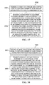
- FIG. 6 illustrates a Physical Uplink Control CHannel (PUCCH) resource partition 600 in one resource block in an uplink (UL) carrier in an LTE system according to an embodiment of this disclosure.
- PUCCH Physical Uplink Control CHannel
- the uplink (UL) ACK/NACK (AN) bits are transmitted on PUCCH formats 1a and 1b.
- Resources used for transmission of PUCCH format 1a/1b are represented by the non-negative index n PUCCH (l) PUCCH resource index n PUCCH (l) determines an orthogonal cover (OC) and a cyclic shift (CS), and these two parameters indicate a unique resource.
- n PUCCH (l) PUCCH resource index
- OC orthogonal cover
- CS cyclic shift
- the next generation communication systems allow for aggregated multiple bandwidths and allow for a UE and an eNodeB to operate in the resultant aggregated carriers.
- the bandwidth aggregation can be symmetric or asymmetric. In the symmetric case, the number of component carriers (CCs) in the UL and the DL are the same. In the asymmetric case, the number of carriers in the UL and the DL can be different.
- ACK/NACK bundling For acknowledging on multiple PDSCHs (e.g., in multiple subframes or in multiple DL component carriers (CCs)), two methods are considered, ACK/NACK bundling and ACK/NACK multiplexing.
- ACK/NACK bundling The main motivation behind ACK/NACK bundling is to reduce the acknowledgement signaling overhead by reducing the number of bits transmitted in the signaling.
- One way of reducing the number of bits is to take a logical AND operation across the multiple ACK/NACK bits corresponding to multiple PDSCHs for each codeword. In a system where up to two codewords are allowed, this bundling would result in two bits for the acknowledgement signal.
- ACK/NACK multiplexing The main motivation behind ACK/NACK multiplexing is to feed individual decoding results of PDSCHs back to an eNodeB.
- spatial bundling is applied, implying that a logical AND operation is taken of ACK/NACK bits across codewords.
- M ACK/NACK bits for acknowledging M PDSCHs, regardless of the number of codewords in each PDSCH transmission.
- a channel selection method is used for feeding multiple ACK/NACK bits back to the eNodeB.
- both a selected PUCCH resource and a modulation symbol carried in the selected PUCCH resource convey information on multiple ACK/NACK bits.
- a UE transmits signals in only n PUCCH resources out of the N PUCCH resources, where n is a natural number less than or equal to M. Typical example values for n are 1 and 2.
- the M-bit information is jointly conveyed by the identity of the n selected channels (or PUCCH resources) and the signals transmitted in each of the n selected channels.
- the identity of a selected PUCCH resource provides 3 codepoints.
- a selected channel (or PUCCH resource) carries a QPSK signal
- a 2-bit information or 4 codepoints
- a UE is equipped with multiple transmit antennas, and is configured by an eNodeB to perform PUCCH transmit diversity.
- PUCCH transmit diversity When the UE is scheduled a DL data (PDSCH) transmission in a subframe in only one DL CC by a DL grant, corresponding dynamic ACK/NACK are transmitted in a later subframe using two PUCCH resources in one UL CC, where the two PUCCH resources carry the identical signals for the ACK/NACK. Furthermore, the two PUCCH resources are transmitted on two uplink transmit antenna ports.
- This method of PUCCH transmit diversity is also known as Orthogonal Resource Transmission, or ORT (or spatial orthogonal resource transmission diversity, SORTD).
- M the number of ACK/NACK symbols that would be conveyed in a transmission in a subframe, is determined by at least one of the following parameters: (1) the number of configured DL CCs, or N, (2) the number of activated DL CCs and (3) the number of DL CCs that have received PDSCHs in a previous subframe for which the UE sends an acknowledgement message in a current subframe.
- M is determined from at least one of the three parameters listed below:
- the number of allocated uplink control channels for the UE's acknowledgement for M DL CCs is determined by a function of at least one of M and L 0 .
- L 0 denotes a number of uplink control channels allocated for the UE when SORTD is not configured.
- L ⁇ L 0 as this allows more channels to select from in case SORTD is configured.
- the L channels for the UE when SORTD is configured include the L 0 channels for the UE when SORTD is NOT configured.
- an uplink control channel (or resource) is defined by a pair of a cyclic shift (CS) and an orthogonal cover code (OCC) located in an uplink physical resource block (UL PRB) as in Rel-8 LTE.
- CS cyclic shift
- OCC orthogonal cover code
- FIG. 7 illustrates an uplink control channel resource allocation 700 for a particular UE depending on whether Spatial Orthogonal-Resource Transmit Diversity (SORTD) is configured or not according to an embodiment of this disclosure.
- SORTD Spatial Orthogonal-Resource Transmit Diversity
- SORTD SORTD is configured, channels 0, 1 and 2 are allocated for UE 0.
- SORTD is not configured, only channels 0 and 1 are allocated for UE 0.
- FIG. 8 illustrates a table 800 that indicates the number of allocated uplink control channels when SORTD is configured according to an embodiment of this disclosure.
- an L value in table 500 is a minimum number satisfying the following conditions:
- Condition 1 L ⁇ 2 (i.e., there are at least two channels to do SORTD), and
- Condition 2 There are at least M possibilities to choose two circularly consecutive channels out of L channels.
- two channels are circularly consecutive if the two channel indices are consecutive, or the two channel indices are 0 and L ⁇ 1, when the L channels are indexed with L consecutive integers, 0, 1, 2, . . . , L ⁇ 1.
- FIG. 9 illustrates a table 900 that indicates the number of allocated uplink control channels when SORTD is configured according to another embodiment of this disclosure.
- a UE configured to perform SORTD and configured to transmit M ACK/NACK symbols in a subframe transmits one modulation symbol in two uplink control channels out of L (where L ⁇ M) allocated channels, where one uplink control channel is transmitted via one uplink antenna port, and the other uplink control channel is transmitted via another uplink antenna port (i.e., SORTD is implemented in the two selected channels).
- an uplink control channel is defined by a pair of a cyclic shift (CS) and an orthogonal cover code (OCC) located in an uplink physical resource block (UL PRB) as in Rel-8 LTE.
- CS cyclic shift
- OCC orthogonal cover code
- the two channels for SORTD are selected by a rule, where the rule is defined by extending an ACK/NACK channel selection method for single-antenna transmissions.
- the modulation symbol transmitted in the two channels is identical to the modulation symbol transmitted in the ACK/NACK channel selection method for single-antenna transmissions.
- the L channels are first indexed in an ascending order in ACK/NACK resource numbers: the lowest numbered channel in ACK/NACK resource numbers would be channel 0, the second lowest numbered channel in ACK/NACK resource numbers would be channel 1, and so on.
- the two selected channels are i and (i+1)mod L.
- the two selected channels are i and (i+M)mod L.
- the two selected channels are i and (i ⁇ 1)mod L.
- L channels can be allocated to a UE.
- TDD Time-Division Duplex
- ACK/NACK multiplexing and a subframe n with M>1 where M is the number of elements in the set K
- spatial ACK/NACK bundling across multiple codewords within a DL subframe is performed by a logical AND operation of all the corresponding individual ACK/NACKs, and PUCCH format 1b with channel selection is used.
- TDD ACK/NACK multiplexing and a subframe n with M 1
- spatial ACK/NACK bundling across multiple codewords within a DL subframe is not performed, 1 or 2 ACK/NACK bits are transmitted using PUCCH format 1a or PUCCH format 1b, respectively.
- a UE transmits b(0), b(1) on an ACK/NACK resource n PUCCH (l) in sub-frame n using PUCCH format 1b.
- FIG. 14 illustrates an ACK/NACK mapping 1400 according to an embodiment of this disclosure.
- FIG. 15 illustrates an ACK/NACK mapping 1500 according to another embodiment of this disclosure.
- Two channels i and (i+M)mod L are selected using table 1100 .
- the first channel i is n PUCCH,l (l) and the second channel is (1+2)mod 4 or n PUCCH,3 (l)
- the first channel i is n PUCCH,0 (l) and the second channel is (0+2)mod 4 or n PUCCH,2 (l) .
- FIG. 17 illustrates an ACK/NACK mapping 1700 according to a further embodiment of this disclosure.
- table 1200 when ACK,ACK,ACK is multiplexed, the first channel i is n PUCCH,2 (l) and the second channel is (2+3)mod 6 or n PUCCH,5 (l) .
- NACK,NACK/DTX,NACK/DTX is multiplexed, the first channel i is n PUCCH,0 (l) and the second channel is (0+3)mod 6 or n PUCCH,3 (l) .
- L uplink control resources for ACK/NACK signal transmissions are allocated to each UE by an eNodeB using a semi-static allocation method.
- the eNodeB transmits an information element about one uplink resource index, n PUCCH , in a higher-layer signaling.
- Each of the L resource indices are then derived from a function of at least one of the one uplink resource index n PUCCH , a separately signalled component carrier (CC)-common resource offset N PUCCH (l) , and L.
- CC component carrier
- the L number is derived by a relation between M and L, where some example relations are shown in table 800 and table 900 .
- the higher-layer signaling is a Radio Resource Control component carrier (RRC CC) configuration signaling to the UE.
- RRC CC Radio Resource Control component carrier
- the UE Upon receiving the one uplink resource index, the UE finds L consecutive uplink control resources starting from the one uplink resource index n PUCCH , for the L uplink control resources for ACK/NACK signal transmissions.
- the higher-layer signaling is a Media Access Control (MAC) component carrier (CC) activation signaling to the UE.
- MAC Media Access Control
- CC component carrier
- the UE is configured by an RRC CC configuration signaling to receive PDSCHs from K CCs, where K ⁇ 5.
- M 1 CCs are activated in subframe n ⁇ 1.
- an M number of CCs out of K configured CCs are activated for the UE in several subframes after subframe n.
- FIG. 18A is a table 1800 depicting information elements (IEs) for Media Access Control component carrier (MAC CC) activation signaling according to an embodiment of this disclosure.
- IEs information elements
- MAC CC Media Access Control component carrier
- N offset,l l ⁇ 1.
- the eNodeB also indicates an identity of one CC that will be activated by the MAC CC activation signaling, where IEs for this MAC CC activation signaling are listed in table 1810 . This can be done by a 2-bit information element (IE), in which each state from the 2-bit field activates a CC according to table 1810 . In this case, M number would be equal to M 1 +1.
- IE 2-bit information element
- N offset,l l ⁇ 1.
- L 2 uplink control resources are de-allocated from L previously allocated uplink control resources.
- L 2 largest-numbered uplink control resources out of L previously allocated uplink control resources are released (or de-allocated).
- L 2 smallest-numbered uplink control resources out of L previously allocated uplink control resources are released (or de-allocated).
- a UE determines up to A uplink control channels for each Tx antenna port to convey an A-bit HARQ-ACK message using a channel selection scheme.
- an uplink control channel (or resource) is defined by at least one of a cyclic shift (CS) and an orthogonal cover code (OCC) located in an uplink physical resource block (UL PRB), for example, PUCCH format 1a/1b in Rel-8 LTE.
- CS cyclic shift
- OOCC orthogonal cover code
- a UE is configured to transmit HARQ-ACK using channel selection on two antenna ports (or configured to do SORTD).
- the UE In order for the UE to transmit a HARQ-ACK message mapped to a selected channel i and a QPSK symbol q on the selected channel according to a mapping table (e.g., table 1100 , table 1200 and table 1300 ), the UE selects channel i from the A uplink control channels determined for each antenna port, and transmits a QPSK symbol q on each antenna port.
- a mapping table e.g., table 1100 , table 1200 and table 1300
- FIG. 19 illustrates a HARQ-ACK message transmission 1900 when two antennas are configured according to an embodiment of this disclosure.
- ACK,ACK HARQ-ACK message
- a UE is configured to receive from a primary cell (or PCC) and a secondary cell (or SCC).
- the transmission modes configured for the PCC and SCC are such that up to N 1 and N 2 TBs can be transmitted in the PCC and in the SCC, respectively.
- N 1 , N 2 ⁇ 1,2 ⁇ .
- the A uplink control channels to be used for a channel selection scheme on each antenna port can be found as follows:
- the PUCCH resources are determined as follows:
- FIG. 20 illustrates a determination 2000 of a second set of control channels for antenna port p 1 according to an embodiment of this disclosure.
- n offset 1.
- uplink control channels 10, 11, 15 and 16 are determined for antenna port p 0
- uplink control channels 11, 12, 16 and 17 are determined for antenna port p 1 .
- the uplink control channels that the eNodeB has to monitor to decode a HARQ-ACK message are 10, 11, 12, 15, 16 and 17.
- the eNodeB has to assign 6 uplink control channels for the UE.
- FIG. 21 illustrates a determination 2100 of a second set of control channels for antenna port p 1 according to another embodiment of this disclosure.
- n offset 1.
- uplink control channels 10, 11, 15 and 16 are determined for antenna port p 0
- uplink control channels 10, 11, 15 and 16 are determined for antenna port p 1 .
- the uplink control channels that the eNodeB has to monitor to decode a HARQ-ACK message are 10, 11, 15 and 16.
- the eNodeB has to assign 4 uplink control channels for the UE.
- the control channels for antenna port p 0 are semi-statically allocated, the UE knows all the A channels for antenna port p 0 in any of the subframes the UE transmits HARQ-ACK.
- SIMO Single Input Multiple Output
- the next example function (denoted as example function 4) is considered.
- the channels for the second antenna port are determined based on the HARQ-ACK payload in a HARQ-ACK message.
- one additional channel is determined for the second antenna port, where the additional channel is located next to a channel for the first antenna port determined for a cell with 1-TB transmission mode.
- the other channels for the second antenna port are determined based on Equation 4.
- FIG. 22 illustrates a determination 2200 of a second set of control channels for antenna port p 1 according to a further embodiment of this disclosure.
- n offset 1.
- uplink control channels 10, 11 and 15 are determined for antenna port p 0
- uplink control channels 11, 15 and 16 are determined for antenna port p 1 .
- the uplink control channels that the eNodeB has to monitor to decode a HARQ-ACK message are 10, 11, 15, 16.
- eNodeB has to assign 4 uplink control channels for the UE.
- FIG. 22 assumes a fallback-friendly mapping characterized as follows:
- a DL grant dynamically determines two uplink control channels for the first antenna port, or, antenna port p 0 .
- this embodiment ensures that the UE can find a control channel to be used by the second antenna port, even when the eNodeB transmits two DL grants but the UE misses one out of the two. This can be seen in the following:
- the C number of configured component carriers is 2
- two-cell aggregation is expected to be the most frequently configured in practice, it would be better to optimize the HARQ-ACK transmission for the two-cell aggregation so that a UE can report a variable number of HARQ-ACK bits, depending on the configured transmission modes in the two cells.
- a set of channel selection tables optimized for two-cell aggregation does not ensure a good tradeoff between performance and UE complexity.
- a simpler channel selection rule e.g., Rel-8 channel selection mapping with spatial bundling, is applied when the number of configured component carriers is greater than 2.
- FIGS. 23A and 23B illustrate data transmission over two antennas using slot-based precoding vector switching (PVS) or time switched transmit diversity (TSTD) according to an embodiment of this disclosure.
- PVS slot-based precoding vector switching
- TSTD time switched transmit diversity
- a UE utilizes a specification-transparent transmit diversity scheme to transmit a dynamic ACK/NACK modulation symbol in a single PUCCH resource which is mapped by the one control channel element (CCE).
- CCE control channel element
- the ACK/NACK modulation symbol is multiplexed with the same CS and OC mapping to one CCE, and then the data are transmitted over two antennas using slot-based precoding vector switching (PVS) or time switched transmit diversity (TSTD), which preserves single-carrier (SC) property and employs one orthogonal resource for DMRS and control data.
- PVS slot-based precoding vector switching
- TSTD time switched transmit diversity
- a UE may receive data signals (or PDSCHs) from a number of DL component carriers (CCs).
- CCs DL component carriers
- the eNodeB sends the UE at least one downlink transmission grant.
- an eNodeB assigns a number of DL CCs, say N DL CCs, to a UE, through which the eNodeB transmits data signals to the UE.
- the eNodeB sends N DL grants to the UE in the N DL CCs, one DL grant in each of these DL CCs.
- the eNodeB sends N DL grants to the UE in only one DL CC, where these DL grants may have a carrier-indicator field, which indicate a CC that a DL grant schedules a PDSCH in.
- a DL grant can be alternatively be referred to as a PDCCH (physical downlink control channel), PDCCH grant, or a downlink control information (DCI) assignment.
- a DL anchor CC and an UL anchor CC can be configured in a UE-specific way or in a cell-specific way.
- the DL anchor CC for a UE is a DL CC that carries a DL grant for the UE in all the subframes in which the UE receives data signals. In other words, when the UE receives at least one DL grant in a subframe, the DL anchor CC will carry a DL grant for the UE.
- the one UL anchor CC for a UE is an UL CC that carries uplink control information for a UE, such as dynamic ACK/NACKs that corresponds to DL data transmissions in the N DL CCs in earlier subframes.
- a UE's method of transmitting acknowledgement signals depends on the number of DL CCs that have carried PDCCH DL grants in a corresponding DL subframe.
- acknowledgement signals are transmitted as follows:
- the UE When only one DL CC (i.e., a DL anchor) carries a DL grant for a UE, the UE transmits a corresponding ACK/NACK bits using the LTE Rel-8 method of ACK/NACK transmission in FDD.
- the UE uses a specification-transparent transmit diversity scheme to transmit an ACK/NACK modulation symbol in a PUCCH D-ACK resource.
- the UE When more than one DL CCs carry a DL grant for a UE, the UE transmits corresponding ACK/NACK bits using ACK/NACK multiplexing method by a channel selection method.
- FIG. 24 illustrates a method 2400 of ACK/NACK transmission at a UE when ACK/NACK multiplexing is utilized according to an embodiment of this disclosure.
- method 2400 includes determining whether more than one DL CC carry the PDSCHs (block 2401 ).
- the N number of DL CCs that carried the PDSCHs and the M number of CCEs that carried a PDCCH DL grant in the DL anchor CC are determined (block 2403 ).
- N number of CCEs for D-ACK resources mapping are selected (block 2405 ).
- the N number of CCEs are mapped to N D-ACK resources (block 2407 ).
- ACK/NACK multiplexing is performed by a channel selection method utilizing the N D-ACK resources (block 2409 ).
- the modulation symbols are then mapped to the selected D-ACK resources in the antenna ports (block 2411 ).
- one or two CCEs for D-ACK resources mapping are selected (block 2413 ).
- the one or two CCEs are mapped to one or two D-ACK resources (block 2415 ).
- One modulation symbol is selected for the D-ACK signal (block 2417 ).
- the modulation symbol is then mapped to the one or two D-ACK resources in the antenna port (block 2411 ).
- acknowledgement signals are transmitted as follows:
- the UE When only one DL CC (i.e., a DL anchor) carries a DL grant for a UE, the UE transmits corresponding ACK/NACK bits using the LTE Rel-8 method of ACK/NACK transmission in FDD.
- the UE uses a specification-transparent transmit diversity scheme to transmit an ACK/NACK modulation symbol in a PUCCH D-ACK resource.
- the UE When more than one DL CCs carry a DL grant for a UE, the UE transmits corresponding ACK/NACK bits using an ACK/NACK bundling method.
- FIG. 25 illustrates a method 2500 of ACK/NACK transmission at a UE when ACK/NACK bundling is utilized according to an embodiment of this disclosure.
- method 2500 includes determining the N number of DL CCs that carried the PDSCHs and the M number of CCEs that carried a PDCCH DL grant in the DL anchor CC (block 2501 ).
- One or two CCEs for D-ACK resources mapping are selected (block 2503 ).
- the one or two CCEs are mapped to one or two D-ACK resources (block 2505 ).
- One modulation symbol is selected for the D-ACK signal (block 2511 ).
- the modulation symbol is then mapped to the one or two D-ACK resources in the antenna port (block 2513 ).
- UL control resources for a UE's dynamic ACK/NACKs which acknowledge on a corresponding DL data transmission in N DL CCs are located in an UL anchor CC for the UE. Furthermore, the UL control resources are determined by CCEs that carry a DL grant in a DL anchor CC for the previous DL data transmission for the UE. The size of the UL control resources is the same as the number of DL CCs that have been used in the previous DL data transmission, or N.
- FIG. 26 illustrates a method 2600 of selecting N CCEs for D-ACK resource mapping according to an embodiment of this disclosure.
- Some embodiments of this disclosure describe the selection of N CCEs for D-ACK resource mapping, for example, the selection of the N number of CCEs for D-ACK resources mapping at block 2405 of FIG. 24 .
- the selection of N CCEs for D-ACK resource mapping includes determining whether N ⁇ M (block 2601 ). Depending on the M number of CCEs that carry the DL grant in the DL anchor CC and the N number of PDSCHs, two different methods are utilized for the selection of the N CCEs for D-ACK resource mapping as illustrated in FIG. 26 .
- the M number CCEs that carry the DL grant in the DL anchor CC is larger than or equal to the number of DL CCs used in the previous DL data transmission, or N.
- N CCEs out of the M CCEs are used for determining the UL control resources for the UE's dynamic ACK/NACK (block 2603 ).
- the N CCEs having the N smallest CCE index numbers out of the M CCEs are used.
- the N CCEs having the N largest CCE index numbers from the M CCEs are used.
- the M number of CCEs that carry the DL grant in the DL anchor CC is smaller than the number of DL CCs used in the previous DL data transmission, or N.
- all the M CCEs are used for determining M UL control resources for the UE's dynamic ACK/NACK.
- the remaining (N ⁇ M) UL control resources are determined by (N ⁇ M) CCE numbers from the remaining CCE numbers other than the M CCE numbers. There can be multiple methods of choosing the (N ⁇ M) CCE numbers.
- CCEs corresponding to the (N ⁇ M) CCE numbers are referred to as reserved CCEs (block 2605 ).
- the (N ⁇ M) CCE numbers are (N ⁇ M) consecutive numbers chosen from CCE numbers of CCEs sharing a same parent node in a CCE search space tree as the M aggregated CCEs carrying the PDCCH or DL grant.
- One way of choosing the (N ⁇ M) CCE numbers in this embodiment is to choose the largest-numbered CCEs from those CCEs sharing the same parent node as the M aggregated CCEs carrying the DL grant.
- FIG. 27 illustrates a method 2700 of CCE resource reservation for ACK/NACK transmissions according to an embodiment of this disclosure.
- CCEs i.e., CCEs 5 through 8
- CCEs 5 through 8 carry a DL, grant for a UE in a subframe.
- N the total number of DL grants for the UE in the subframe
- CCEs sharing a same parent node as CCEs 5 through 8 are CCEs 1 through 4, and the largest two CCE numbers from 1 through 4 are 3 and 4.
- CCEs 3 and 4 are reserved for the UE's ACK/NACK transmissions.
- the smallest-numbered CCEs from those CCEs sharing the same parent node are chosen as the M aggregated CCEs carrying the DL grant.
- only one set of dynamic ACK/NACK resources is allocated in an UL CC, implying that the UEs will receive one offset index N PUCCH (l) for a mapping rule of CCE numbers to ACK/NACK resources.
- the offset index N PUCCH (l) is configured by higher layers according to the Rel-8 LTE specifications.
- mapping the N CCE indices to N UL ACK/NACK resources is described as follows:
- FIG. 28 illustrates CCE to ACK/NACK mapping 2800 when only one N PUCCH (l) index number is signaled according to an embodiment of this disclosure.
- two sets of dynamic ACK/NACK resources are allocated in an UL CC, implying that the UEs will receive two offset indices N PUCCH,1 (l) and N PUCCH,2 (l) for a mapping rule of CCE numbers to ACK/NACK resources.
- One offset index N PUCCH,l (l) is equal to a N PUCCH (l) which is configured by higher layers according to the Rel-8 LTE specifications.
- the other offset index N PUCCH,2 (l) is configured by higher layers for advanced users (e.g., Rel-10 LTE-A UEs).
- N PUCCH ACK/NACK resources one group of resources are determined by N PUCCH,1 (l) and a corresponding number of CCE index numbers among the N CCE numbers.
- the other groups of resources are determined by N PUCCH,2 (l) and a corresponding number of CCE index numbers.
- This disclosure also describes other embodiments of mapping of N CCE numbers to D-ACK resources, for example in block 2407 of FIG. 24 .
- mapping the N CCE indices to N UL ACK/NACK resources is described as follows:
- the usage of the reserved CCEs is restricted at the eNodeB.
- the reserved CCEs cannot be used for DL grant for another advanced UE (e.g., Rel-10 UE), as doing so may result in dynamic ACK/NACK resource collision.
- the reserved CCEs can be used for other purposes, for example, DL grant for Rel-8 LTE UE, UL grant, common control, and so on.
- n CCE,k is the k-th smallest CCE number out of the N CCE numbers.
- the first M PUCCH ACK/NACK resources are determined by the M CCEs used for transmission of the corresponding DCI assignment, and the rest (N ⁇ M) resources are determined by the max ⁇ N ⁇ M,0 ⁇ reserved CCEs.
- the rest (N ⁇ M) resources are determined by the max ⁇ N ⁇ M,0 ⁇ reserved CCEs.
- n CCE,k is the k-th smallest CCE number from the M CCEs used for transmission of the corresponding DCI assignment
- k>M n CCE,k is the (k ⁇ M)-th smallest CCE number from the (N-M) reserved CCEs.
- FIG. 30 illustrates a method 3000 of ACK/NACK multiplexing according to an embodiment of this disclosure.
- Method 3000 includes determining whether the number of N PDSCHs is greater than or equal to a constant number A (block 3001 ). When the number of N PDSCHs is smaller than the constant number A, one channel selection is used for mapping N ACK/NACK bits to one selected D-ACK resource and one modulation symbol (block 3003 ). On the other hand, when the number of N PDSCHs is greater than or equal to A, two channel selection is used for mapping N ACK/NACK bits to two selected D-ACK resources and two modulation symbols (block 3005 ).
- FIG. 32 illustrates a method 3200 of a mapping of modulation symbol(s) to selected D-ACK resource(s) in antenna port(s) according to another embodiment of this disclosure.
- Method 3200 includes determining whether the number of PDSCHs, N, is more than one or whether ACK/NACK multiplexing is utilized (block 3201 ). When the number of PDSCHs is more than one (or when ACK/NACK multiplexing is utilized), the one modulation symbol is mapped to one PUCCH D-ACK resource utilizing a specification-transparent antenna port mapping (block 3203 ). When the number of PDSCHs is precisely one, the one modulation symbol is mapped to multiple PUCCH D-ACK resources using ORT (block 3205 ). In some embodiments, N is the number of configured DL CCs.
- FIG. 33 illustrates a method 3300 of ACK/NACK multiplexing according to another embodiment of this disclosure.
- Method 3300 includes determining whether the number of N PDSCHs is greater than or equal to a constant number A (block 3301 ). When the number of N PDSCHs is smaller than the constant number A, two D-ACK resources and one modulation symbol are selected for mapping N ACK/NACK bits (block 3303 ). On the other hand, when the number of PDSCHs is greater than or equal to the constant number A, two D-ACK resources and two modulation symbols are selected for mapping N ACK/NACK bits (block 3305 ).
- Method 3400 includes determining whether the number of N PDSCHs is greater than or equal to a constant number A (block 3401 ). In particular, when N ⁇ A, the UE maps one modulation symbol to multiple antenna ports using ORT (block 3403 ). When N ⁇ A, the UE maps two modulation symbols in two PUCCH D-ACK resources in two transmit antennas (block 3405 ).
- Particular embodiments relate to cases in which only a DL anchor CC carries those codepoints.
- the eNodeB when an eNodeB decides to transmit data to a UE using a DL transmission scheme, say DL transmission scheme X, the eNodeB transmits a DL grant of a DCI format, say DCI format Y, to the UE in a subframe.
- the codepoints in a DL grant in the anchor CC that indicate the total number of DL grants transmitted in non-anchor DL CCs can be provided by an additional field in DCI format Y.
- the additional field could be identical to the carrier indicator field.
- the number of bits assigned to the additional field is a cell-specific constant, e.g., 2 or 3 bits, or a UE-specific number that may depend on the number of configured CCs for a UE.
- DCI format Y include DL grant DCI formats 1, 1A, 2A, 2B, etc., defined in an LTE specification (Rel-8, Rel-9 and Rel-10).
- Such embodiments are useful for the detection of discontinuous transmission, also known as DTX.
- DTX occurs as a UE does not know that an eNodeB has transmitted a DL grant, a corresponding ACK/NACK cannot be fed back to the eNodeB.
- a DTX is detected at the eNodeB by detecting ACK/NACK signals from the UE at an associated ACK/NACK resource with the DL grant.
- DTX may not be successfully detected at the eNodeB if at least one DL grant is missed at the UE. As the total number of DL CCs is signalled, DTX can be detected if at least one DL grant is successfully detected at a UE.
- FIG. 35 illustrates a method 3500 of operating a base station according to an embodiment of this disclosure.
- method 3500 includes transmitting a downlink (DL) grant, data streams, and a control signal to configure a number of uplink transmit antenna ports for physical uplink control channel (PUCCH) to a subscriber station (block 3501 ).
- Method 3500 also includes receiving ACKnowledgement/Negative ACKnowledgement (ACK/NACK) from the subscriber station in response to the data streams (block 3503 ). If the subscriber station is configured by the base station to transmit ACK/NACK using one uplink transmit antenna port and channel selection with PUCCH format 1B, a modulation symbol is transmitted on one physical uplink control channel (PUCCH) i determined based at least partly upon a channel selection mapping table.
- PUCCH physical uplink control channel
- the ACK/NACK modulation symbol is transmitted on two PUCCHs.
- a first channel of the two PUCCHs is PUCCH i determined based at least partly upon the channel selection mapping table and a second channel of the two PUCCHs is determined implicitly by a function depending on at least one of i, L, and M, where L is a number of uplink control channels allocated for the subscriber station's ACK/NACK, and M is a number of ACK/NACK bits conveyed in a transmission in a subframe.
- FIG. 36 illustrates a method 3600 of operating a subscriber station according to an embodiment of this disclosure.
- method 3600 includes receiving a downlink (DL) grant, data streams, and a control signal to configure a number of uplink transmit antenna ports for physical uplink control channel (PUCCH) from a base station (block 3601 ).
- the method includes transmitting ACKnowledgement/Negative ACKnowledgement (ACK/NACK) to the base station in response to the data streams (block 3603 ). If the subscriber station is configured by the base station to transmit ACK/NACK using one uplink transmit antenna port and channel selection with PUCCH format 1B, a modulation symbol is transmitted on one physical uplink control channel (PUCCH) i determined based at least partly upon a channel selection mapping table.
- PUCCH physical uplink control channel
- the ACK/NACK modulation symbol is transmitted on two PUCCHs.
- a first channel of the two PUCCHs is PUCCH i determined based at least partly upon the channel selection mapping table and a second channel of the two PUCCHs is determined implicitly by a function depending on at least one of i, L, and M, where L is a number of uplink control channels allocated for the subscriber station's ACK/NACK, and M is a number of ACK/NACK bits conveyed in a transmission in a subframe.
- FIG. 37 illustrates a method 3700 of operating a base station according to another embodiment of this disclosure.
- method 3700 includes transmitting a downlink (DL) grant, data streams, and a control signal to configure a number of uplink transmit antenna ports for physical uplink control channel (PUCCH) to a subscriber station (block 3701 ).
- the method also includes receiving an ACKnowledgement/Negative ACKnowledgement (ACK/NACK) from the subscriber station in response to the data streams (block 3703 ). If the subscriber station is configured by the base station to transmit ACK/NACK using two uplink transmit antenna ports and channel selection with PUCCH format 1B, the configuration of two uplink transmit antenna ports is overridden and the modulation symbol is mapped to only one PUCCH on one transmit antenna port. If the subscriber station is configured by the base station to transmit ACK/NACK using two uplink transmit antenna ports and PUCCH format 1A/1B, the modulation symbol is mapped onto two uplink transmit antenna ports on two PUCCHs.
- DL downlink
- PUCCH physical uplink control channel
- FIG. 38 illustrates a method 3800 of operating a subscriber station according to another embodiment of this disclosure.
- method 3800 includes receiving a downlink (DL) grant, data streams, and a control signal to configure a number of uplink transmit antenna ports for physical uplink control channel (PUCCH) from a base station (block 3801 ).
- the method includes transmitting ACKnowledgement/Negative ACKnowledgement (ACK/NACK) to the base station in response to the data streams (block 3803 ). If the subscriber station is configured by the base station to transmit ACK/NACK using two uplink transmit antenna ports and channel selection with PUCCH format 1B, the configuration of two uplink transmit antenna ports is overridden and the modulation symbol is mapped to only one PUCCH on one transmit antenna port. If the subscriber station is configured by the base station to transmit ACK/NACK using two uplink transmit antenna ports and PUCCH format 1A/1B, the modulation symbol is mapped onto two uplink transmit antenna ports on two PUCCHs.
- DL downlink
- PUCCH physical uplink control channel
Landscapes
- Engineering & Computer Science (AREA)
- Signal Processing (AREA)
- Computer Networks & Wireless Communication (AREA)
- Quality & Reliability (AREA)
- Mobile Radio Communication Systems (AREA)
Abstract
Description
-
- M is equal to the number of configured DL CCs, or N;
- M is equal to the number of activated DL CCs; and
- M is equal to the number of DL CCs that have received PDSCHs in a previous subframe for which the UE sends an acknowledgement message in a current subframe.
n PUCCH,l (1) =n PUCCH +N PUCCH (l) +N offset,l , l=1,2, . . . , L, [Eqn. 1]
where Noffset,l=l−1. For example, when L=4, the one signalled uplink resource index is used for determining L=4 resources.
n PUCCH,l (1) =n PUCCH +N PUCCH (l) +N offset,l , l=1,2, . . . , L, [Eqn. 2]
where Noffset,l=l−1. For example, when L=4, the one signalled uplink resource index nPUCCH is used for determining L=4L=4 resources.
n PUCCH,l (1) =n PUCCH +N PUCCH (l) +N offset,l , l=1,2, . . . , L−L 1, [Eqn. 3]
where Noffset,l=l−1. For example, when L=4 and L1=2, the one signalled uplink resource index nPUCCH is used for determining 2 (=L−L1) additional resources.
-
- When the PDSCH transmission is on the primary cell,
n PUCCH,i (l,p=p0 ) =n CCE +i+N PUCCH (l), where iε{0, . . . ,N 1−1},
where nCCE is the smallest CCE number used for the transmission of the corresponding DCI assignment and NPUCCH (l) is configured by higher layers. - When the PDSCH transmission is on the secondary cell,
n PUCCH,i (l,p=p0 ) =n CCE +i−N 1 +N PUCCH (l), where iε{N 1 , . . . ,A−1},
where nCCE is the smallest CCE number used for the transmission of the corresponding DCI assignment and NPUCCH (l) is configured by higher layers.
- When the PDSCH transmission is on the primary cell,
{n PUCCH,i (1,p=p
n PUCCH,i (1,p=p
n PUCCH,i (1,p=p
n PUCCH,i (1,p=p
n PUCCH,0 (1,p=p
n PUCCH,i (1,p=p
n PUCCH,i (1,p=p
n PUCCH,2 (1,p=p
n PUCCH,i (1,p=p
n PUCCH,k (1) =n CCE,k +N PUCCH (l) , k=1, 2, . . . ,N, [Eqn. 5]
where nCCE,k is the k-th index number of a CCE out of the N CCEs selected from the M CCEs used for transmission of the corresponding DCI assignment and max {N−M,0} reserved CCEs.
n PUCCH,l (1) =n CCE,l +N PUCCH (l). [Eqn. 6]
n PUCCH,k (1) =n CCE,l +N PUCCH,2 (l) , k=2, 3, . . . ,N [Eqn. 7]
where nCCE,k is the k-th index number of a CCE out of the N CCEs selected from the M CCEs used for transmission of the corresponding DCI assignment and max {N−M,0} reserved CCEs.
Claims (16)
Priority Applications (1)
| Application Number | Priority Date | Filing Date | Title |
|---|---|---|---|
| US14/732,151 US9768934B2 (en) | 2010-03-29 | 2015-06-05 | Method and system for uplink acknowledgement signaling in carrier-aggregated wireless communication systems |
Applications Claiming Priority (5)
| Application Number | Priority Date | Filing Date | Title |
|---|---|---|---|
| US31870310P | 2010-03-29 | 2010-03-29 | |
| US38408110P | 2010-09-17 | 2010-09-17 | |
| US201161434345P | 2011-01-19 | 2011-01-19 | |
| US13/047,557 US20110235599A1 (en) | 2010-03-29 | 2011-03-14 | Method and system for uplink acknowledgement signaling in carrier-aggregated wireless communication systems |
| US14/732,151 US9768934B2 (en) | 2010-03-29 | 2015-06-05 | Method and system for uplink acknowledgement signaling in carrier-aggregated wireless communication systems |
Related Parent Applications (1)
| Application Number | Title | Priority Date | Filing Date |
|---|---|---|---|
| US13/047,557 Division US20110235599A1 (en) | 2010-03-29 | 2011-03-14 | Method and system for uplink acknowledgement signaling in carrier-aggregated wireless communication systems |
Publications (2)
| Publication Number | Publication Date |
|---|---|
| US20150288502A1 US20150288502A1 (en) | 2015-10-08 |
| US9768934B2 true US9768934B2 (en) | 2017-09-19 |
Family
ID=44656422
Family Applications (2)
| Application Number | Title | Priority Date | Filing Date |
|---|---|---|---|
| US13/047,557 Abandoned US20110235599A1 (en) | 2010-03-29 | 2011-03-14 | Method and system for uplink acknowledgement signaling in carrier-aggregated wireless communication systems |
| US14/732,151 Active 2031-04-06 US9768934B2 (en) | 2010-03-29 | 2015-06-05 | Method and system for uplink acknowledgement signaling in carrier-aggregated wireless communication systems |
Family Applications Before (1)
| Application Number | Title | Priority Date | Filing Date |
|---|---|---|---|
| US13/047,557 Abandoned US20110235599A1 (en) | 2010-03-29 | 2011-03-14 | Method and system for uplink acknowledgement signaling in carrier-aggregated wireless communication systems |
Country Status (6)
| Country | Link |
|---|---|
| US (2) | US20110235599A1 (en) |
| EP (1) | EP2553852B1 (en) |
| JP (1) | JP5808791B2 (en) |
| KR (1) | KR101899907B1 (en) |
| CN (2) | CN107104772B (en) |
| WO (1) | WO2011122837A2 (en) |
Families Citing this family (72)
| Publication number | Priority date | Publication date | Assignee | Title |
|---|---|---|---|---|
| CA2777399C (en) | 2009-10-19 | 2015-04-07 | Samsung Electronics Co., Ltd. | Transmission diversity and multiplexing for harq-ack signals in communication systems |
| WO2011158762A1 (en) * | 2010-06-18 | 2011-12-22 | シャープ株式会社 | Mobile communication system, mobile station apparatus, base station apparatus and communication method |
| CN102300313B (en) * | 2010-06-28 | 2013-03-27 | 华为技术有限公司 | Resource allocation method and related device for dedicated demodulation reference signal |
| JP2013535925A (en) * | 2010-08-13 | 2013-09-12 | 富士通株式会社 | Method for transmitting uplink response signal, mobile terminal, and multicarrier communication system |
| US8670410B2 (en) * | 2010-09-17 | 2014-03-11 | Qualcomm Incorporated | Uplink control channel resource mapping for carrier aggregation |
| JP4878651B1 (en) * | 2010-09-17 | 2012-02-15 | シャープ株式会社 | Mobile station apparatus, communication system, communication method, and integrated circuit |
| JP5772960B2 (en) | 2010-09-20 | 2015-09-02 | 富士通株式会社 | Uplink response signal transmission method, base station, mobile station, and communication system |
| KR101771550B1 (en) * | 2010-10-15 | 2017-08-29 | 주식회사 골드피크이노베이션즈 | Method of Transmitting and Receiving Ack/Nack Signal and Apparatus Thereof |
| CN102469596A (en) * | 2010-11-08 | 2012-05-23 | 北京三星通信技术研究有限公司 | ACK/NACK channel resource distributing method capable of supporting channel selection |
| US9106389B2 (en) | 2010-12-23 | 2015-08-11 | Qualcomm Incorporated | Interference randomization for uplink signaling |
| CN102098151B (en) * | 2010-12-28 | 2015-08-12 | 中兴通讯股份有限公司 | A kind of sending method of correct/error response message and user terminal |
| CN102611540A (en) * | 2011-01-20 | 2012-07-25 | 北京三星通信技术研究有限公司 | Method for feeding back ACK/NACK (acknowledgement character/negative acknowledgement) information |
| US10051622B2 (en) * | 2011-03-11 | 2018-08-14 | Lg Electronics Inc. | Method for setting dynamic subframe in wireless communication system and device therefor |
| KR20120120775A (en) * | 2011-04-25 | 2012-11-02 | 주식회사 팬택 | Method and Apparatus for Controlling Multiple Transmission of Control Information Dynamically in Wireless Communication Systems |
| US9001756B2 (en) | 2011-04-27 | 2015-04-07 | Texas Instruments Incorporated | Physical downlink control channel and physical hybrid automatic repeat request indicator channel enhancements |
| CN107465491B (en) | 2011-06-27 | 2021-02-12 | 华为技术有限公司 | Method for determining control channel resources and user equipment |
| US8965917B2 (en) * | 2011-06-28 | 2015-02-24 | Amazon Technologies, Inc. | Optimizing cell search in a mobile communication system supporting variable channel bandwidths |
| US9143215B2 (en) * | 2011-08-11 | 2015-09-22 | Blackberry Limited | Orthogonal resource selection transmit diversity and resource assignment |
| US9900131B2 (en) | 2011-08-15 | 2018-02-20 | Telefonaktiebolaget Lm Ericsson (Publ) | Flexible transmission of messages in a wireless communication system with multiple transmit antennas |
| KR102094890B1 (en) * | 2011-08-19 | 2020-04-14 | 엘지전자 주식회사 | Method for transmitting uplink control information, user equipment, method for receiving uplink control information, and base station |
| CN103828256A (en) * | 2011-09-26 | 2014-05-28 | Lg电子株式会社 | Method and apparatus for transmitting uplink control signal in wireless communication system |
| US8971250B2 (en) | 2011-10-29 | 2015-03-03 | Ofinno Technologies, Llc | Special subframe allocation |
| US8937918B2 (en) | 2011-10-29 | 2015-01-20 | Ofinno Technologies, Llc | Efficient special subframe allocation |
| US11696300B2 (en) | 2011-10-29 | 2023-07-04 | Comcast Cable Communications, Llc | Configuration of reduced transmission power time intervals based on traffic load |
| CN102420644B (en) * | 2011-11-04 | 2014-08-20 | 电信科学技术研究院 | Sending method, receiving method and equipment based on user dedicated reference signal |
| CN102412883B (en) * | 2011-11-04 | 2017-07-07 | 中兴通讯股份有限公司 | The sending method and device of ascending control information |
| CN102394685B (en) * | 2011-11-04 | 2017-07-11 | 中兴通讯股份有限公司 | The sending method and system of multi-aerial system up control channel |
| US8873467B2 (en) | 2011-12-05 | 2014-10-28 | Ofinno Technologies, Llc | Control channel detection |
| CN103988559B (en) * | 2011-12-20 | 2018-02-23 | 英特尔公司 | Use the multicast service of unicast sub-frame |
| US8971275B2 (en) | 2011-12-31 | 2015-03-03 | Ofinno Technologies, Llc | Almost blank subframe indication in wireless networks |
| CN103199961A (en) | 2012-01-06 | 2013-07-10 | 北京三星通信技术研究有限公司 | Method adopting transmission diversity technique to transmit HARQ-ACK information |
| JP6219846B2 (en) | 2012-01-18 | 2017-10-25 | エルジー エレクトロニクス インコーポレイティド | Method and apparatus for improved control channel based operation in a wireless communication system |
| CN103220073A (en) * | 2012-01-20 | 2013-07-24 | 中兴通讯股份有限公司 | Informing and receiving method of downlink demodulation pilot frequency control signaling, base station and terminal |
| CN103313404B (en) | 2012-03-16 | 2017-06-13 | 华为技术有限公司 | A kind of control channel resource transmission method, user equipment and base station |
| JP6031088B2 (en) * | 2012-03-19 | 2016-11-24 | 京セラ株式会社 | Mobile communication system, radio base station, and mobile communication method |
| CN103378954B (en) | 2012-04-20 | 2019-03-15 | 北京三星通信技术研究有限公司 | Method for allocating HARQ-ACK channel resources supporting transmit diversity and channel selection |
| EP2858446B1 (en) * | 2012-06-28 | 2023-02-15 | Huawei Technologies Co., Ltd. | Method for transmitting feedback information for downlink data |
| WO2014017746A1 (en) * | 2012-07-27 | 2014-01-30 | 엘지전자 주식회사 | Method and terminal for performing harq |
| WO2014048472A1 (en) * | 2012-09-27 | 2014-04-03 | Huawei Technologies Co., Ltd. | Methods and nodes in a wireless communication system |
| US9344974B2 (en) | 2012-10-12 | 2016-05-17 | Intel Corporation | Methods and arrangements to coordinate communications of different types of devices on a wireless network |
| KR101749841B1 (en) * | 2012-10-26 | 2017-06-21 | 인텔 코포레이션 | Physical uplink control channel (pucch) resource allocation (ra) for a hybrid automatic retransmission request-acknowledge (harq-ack) transmission |
| FR3000864B1 (en) * | 2013-01-10 | 2015-02-27 | Awox | SOUND SIGNAL DIFFUSION SYNCHRONIZATION DEVICE AND SOUND DIFFUSER |
| JP6162823B2 (en) * | 2013-01-11 | 2017-07-12 | インターデイジタル パテント ホールディングス インコーポレイテッド | System and method for adaptive modulation |
| WO2014109682A1 (en) * | 2013-01-11 | 2014-07-17 | Telefonaktiebolaget Lm Ericsson (Publ) | Interference alignment based precoding method for reducing bandwidth of the backhaul network |
| WO2014108719A1 (en) * | 2013-01-11 | 2014-07-17 | Agence Spatiale Européenne | Transmit power control in a spread spectrum unslotted random access communication system. |
| WO2014109797A1 (en) | 2013-01-14 | 2014-07-17 | Intel IP Corporation | Energy-harvesting devices in wireless networks |
| WO2014112707A1 (en) * | 2013-01-16 | 2014-07-24 | 엘지전자 주식회사 | Method for performing backoff in wireless lan system and apparatus therefor |
| JP6006881B2 (en) * | 2013-01-31 | 2016-10-12 | エルジー エレクトロニクス インコーポレイティド | Reception confirmation response transmission method and apparatus in wireless communication system |
| WO2015013862A1 (en) | 2013-07-29 | 2015-02-05 | Qualcomm Incorporated | Dynamic indication of time division (tdd) duplex uplink/downlink subframe configurations |
| WO2015018073A1 (en) * | 2013-08-09 | 2015-02-12 | Qualcomm Incorporated | Hybrid a/n bundling and multiplexing in eimta |
| WO2015139269A1 (en) * | 2014-03-20 | 2015-09-24 | 华为技术有限公司 | Information transmission method and device |
| WO2016037317A1 (en) * | 2014-09-09 | 2016-03-17 | Nec Corporation | Method and apparatus for mitigating interference and associated computer-readable storage medium and computer program product |
| CN105406952B (en) * | 2014-09-10 | 2019-06-21 | 北京信威通信技术股份有限公司 | A kind of uplink authorization methods, devices and systems |
| WO2016095132A1 (en) * | 2014-12-17 | 2016-06-23 | Qualcomm Incorporated | Techniques for configuring feedback transmission in wireless communications |
| WO2016183737A1 (en) * | 2015-05-15 | 2016-11-24 | Qualcomm Incorporated | Enhanced csi procedures for fd-mimo |
| JP5825451B1 (en) * | 2015-07-01 | 2015-12-02 | 富士通株式会社 | Uplink response signal transmission method, base station, mobile station, and communication system |
| WO2017010798A1 (en) * | 2015-07-14 | 2017-01-19 | 엘지전자 주식회사 | Method and user equipment for receiving downlink signal, and method and base station for transmitting downlink signal |
| WO2018007538A1 (en) * | 2016-07-07 | 2018-01-11 | Fraunhofer-Gesellschaft zur Förderung der angewandten Forschung e.V. | Data transmission in a wireless communication system with reduced latency |
| US10425923B2 (en) * | 2016-08-01 | 2019-09-24 | Qualcomm Incorporated | Uplink channel multiplexing and waveform selection |
| US10567286B2 (en) | 2016-08-09 | 2020-02-18 | Qualcomm Incorporated | Congestion control for LTE-V2V |
| CN106357372A (en) * | 2016-11-15 | 2017-01-25 | 珠海市魅族科技有限公司 | Method and device for avoiding feedback message resource conflict as well as base station and terminal |
| CN114944903B (en) * | 2017-05-03 | 2024-04-26 | Lg电子株式会社 | Method and device for transmitting/receiving signals by a terminal and a base station in a wireless communication system |
| EP3667971B1 (en) * | 2017-08-10 | 2022-10-05 | LG Electronics Inc. | Method for transmitting and receiving uplink control channel and device therefor |
| CN109560906B (en) * | 2017-09-27 | 2021-03-19 | 北京紫光展锐通信技术有限公司 | Feedback method, device and user equipment for uplink control information |
| US10447499B2 (en) * | 2017-10-06 | 2019-10-15 | At&T Intellectual Property I, L.P. | Virtual private network interworking |
| EP3661103B1 (en) * | 2017-11-03 | 2022-07-13 | LG Electronics Inc. | Method for transmitting plurality of slot-based long pucchs in wireless communication system and apparatus therefor |
| CN110460413B (en) * | 2018-01-26 | 2020-11-20 | 华为技术有限公司 | A communication method and device |
| US10454715B1 (en) * | 2018-05-03 | 2019-10-22 | At&T Intellectual Property I, L.P. | Virtual private wire service interworking |
| TWI732302B (en) * | 2018-09-28 | 2021-07-01 | 聯發科技股份有限公司 | Methods and electronic apparatus for uplink transmission |
| WO2020091559A1 (en) * | 2018-11-02 | 2020-05-07 | 엘지전자 주식회사 | Method and device for transmitting and receiving signals in wireless communication system |
| US11558862B2 (en) * | 2020-04-24 | 2023-01-17 | Qualcomm Incorporated | Codepoint scrambling for a non-coherent transmission |
| US12081337B2 (en) * | 2020-06-12 | 2024-09-03 | Qualcomm Incorporated | Hybrid automatic repeat request feedback with multiple uplink channels |
Citations (21)
| Publication number | Priority date | Publication date | Assignee | Title |
|---|---|---|---|---|
| JP2005236686A (en) | 2004-02-19 | 2005-09-02 | Nippon Telegr & Teleph Corp <Ntt> | Communication system and communication method using adaptive array antenna |
| CN101465720A (en) | 2009-01-23 | 2009-06-24 | 中兴通讯股份有限公司 | Method and device for sending upward HARQ feedback information |
| CN101488832A (en) | 2009-01-19 | 2009-07-22 | 中兴通讯股份有限公司 | Channel detecting and processing method, terminal and base station |
| US20090204863A1 (en) | 2008-02-03 | 2009-08-13 | Lg Electronics Inc. | Method and apparatus for supporting harq |
| US20090207797A1 (en) * | 2008-02-19 | 2009-08-20 | Zukang Shen | Mapping between Logical and Physical Uplink Control Resource Blocks in Wireless Networks |
| WO2009130543A1 (en) | 2008-04-25 | 2009-10-29 | Nokia Corporation | Signaling part of semi-persistent configuration via downlink control channel |
| WO2009154540A1 (en) | 2008-06-19 | 2009-12-23 | Telefonaktiebolaget L M Ericsson (Publ) | Method and apparatus in a telecommunications network |
| WO2010013963A2 (en) | 2008-07-30 | 2010-02-04 | Lg Electronics Inc. | Method and apparatus of transmitting control information in wireless communication system |
| WO2010018977A2 (en) | 2008-08-11 | 2010-02-18 | Lg Electronics Inc. | Method and apparatus of transmitting information in wireless communication system |
| US20100135273A1 (en) * | 2007-03-29 | 2010-06-03 | Lg Electrinics Inc. | Method of transmitting sounding reference signal in wireless communication system |
| US20100172290A1 (en) * | 2009-01-08 | 2010-07-08 | Samsung Electronics Co., Ltd. | System and method for an uplink acknowledgement transmission in carrier-aggregated wireless communication systems |
| US20100291937A1 (en) * | 2009-05-15 | 2010-11-18 | Yang Hu | Resource selection for transmission of multiple ack/nack on pucch channel |
| US20110080876A1 (en) * | 2009-10-02 | 2011-04-07 | Sharp Laboratories Of America, Inc. | Transmission diversity scheme on physical uplink control channel (pucch) with ack/nack differentiation |
| US20110080880A1 (en) * | 2009-10-02 | 2011-04-07 | Sharp Laboratories Of America, Inc. | Transmission diversity scheme on physical uplink control channel (pucch) with ack/nack differentiation |
| US20110090825A1 (en) * | 2009-10-19 | 2011-04-21 | Samsung Electronics Co., Ltd. | Transmission diversity and multiplexing for harq-ack signals in communication systems |
| US20110092240A1 (en) * | 2008-04-17 | 2011-04-21 | Sharp Kabushiki Kaisha | Mobile station apparatus, communication system and communication method |
| US20110199997A1 (en) * | 2008-11-04 | 2011-08-18 | Huawei Technologies Co., Ltd. | Method, apparatus and system for determining resource indices |
| US8108757B2 (en) * | 2008-03-16 | 2012-01-31 | Lg Electronics Inc. | Method for effectively transmitting control signal in wireless communication system |
| US20120093139A1 (en) * | 2009-04-20 | 2012-04-19 | Kari Juhani Hooli | Methods, Apparatuses and Computer Program Products |
| US20120127950A1 (en) * | 2009-08-17 | 2012-05-24 | Jae Hoon Chung | Method and apparatus for allocating an uplink carrier for transmitting uplink control information in a wireless communication system |
| US8369884B2 (en) * | 2007-02-28 | 2013-02-05 | Ntt Docomo, Inc. | Base station apparatus and communication control method |
Family Cites Families (2)
| Publication number | Priority date | Publication date | Assignee | Title |
|---|---|---|---|---|
| KR101319870B1 (en) * | 2006-01-05 | 2013-10-18 | 엘지전자 주식회사 | Method for handover in mobile communication system |
| CN101577941A (en) * | 2008-05-06 | 2009-11-11 | 华为技术有限公司 | Method and system for information feedback of uplink control channel, base station and mobile station |
-
2011
- 2011-03-14 US US13/047,557 patent/US20110235599A1/en not_active Abandoned
- 2011-03-29 JP JP2013502472A patent/JP5808791B2/en active Active
- 2011-03-29 CN CN201610982407.8A patent/CN107104772B/en active Active
- 2011-03-29 CN CN201180017256.8A patent/CN102845012B/en not_active Expired - Fee Related
- 2011-03-29 KR KR1020127028325A patent/KR101899907B1/en active Active
- 2011-03-29 WO PCT/KR2011/002163 patent/WO2011122837A2/en not_active Ceased
- 2011-03-29 EP EP11763009.5A patent/EP2553852B1/en active Active
-
2015
- 2015-06-05 US US14/732,151 patent/US9768934B2/en active Active
Patent Citations (21)
| Publication number | Priority date | Publication date | Assignee | Title |
|---|---|---|---|---|
| JP2005236686A (en) | 2004-02-19 | 2005-09-02 | Nippon Telegr & Teleph Corp <Ntt> | Communication system and communication method using adaptive array antenna |
| US8369884B2 (en) * | 2007-02-28 | 2013-02-05 | Ntt Docomo, Inc. | Base station apparatus and communication control method |
| US20100135273A1 (en) * | 2007-03-29 | 2010-06-03 | Lg Electrinics Inc. | Method of transmitting sounding reference signal in wireless communication system |
| US20090204863A1 (en) | 2008-02-03 | 2009-08-13 | Lg Electronics Inc. | Method and apparatus for supporting harq |
| US20090207797A1 (en) * | 2008-02-19 | 2009-08-20 | Zukang Shen | Mapping between Logical and Physical Uplink Control Resource Blocks in Wireless Networks |
| US8108757B2 (en) * | 2008-03-16 | 2012-01-31 | Lg Electronics Inc. | Method for effectively transmitting control signal in wireless communication system |
| US20110092240A1 (en) * | 2008-04-17 | 2011-04-21 | Sharp Kabushiki Kaisha | Mobile station apparatus, communication system and communication method |
| WO2009130543A1 (en) | 2008-04-25 | 2009-10-29 | Nokia Corporation | Signaling part of semi-persistent configuration via downlink control channel |
| WO2009154540A1 (en) | 2008-06-19 | 2009-12-23 | Telefonaktiebolaget L M Ericsson (Publ) | Method and apparatus in a telecommunications network |
| WO2010013963A2 (en) | 2008-07-30 | 2010-02-04 | Lg Electronics Inc. | Method and apparatus of transmitting control information in wireless communication system |
| WO2010018977A2 (en) | 2008-08-11 | 2010-02-18 | Lg Electronics Inc. | Method and apparatus of transmitting information in wireless communication system |
| US20110199997A1 (en) * | 2008-11-04 | 2011-08-18 | Huawei Technologies Co., Ltd. | Method, apparatus and system for determining resource indices |
| US20100172290A1 (en) * | 2009-01-08 | 2010-07-08 | Samsung Electronics Co., Ltd. | System and method for an uplink acknowledgement transmission in carrier-aggregated wireless communication systems |
| CN101488832A (en) | 2009-01-19 | 2009-07-22 | 中兴通讯股份有限公司 | Channel detecting and processing method, terminal and base station |
| CN101465720A (en) | 2009-01-23 | 2009-06-24 | 中兴通讯股份有限公司 | Method and device for sending upward HARQ feedback information |
| US20120093139A1 (en) * | 2009-04-20 | 2012-04-19 | Kari Juhani Hooli | Methods, Apparatuses and Computer Program Products |
| US20100291937A1 (en) * | 2009-05-15 | 2010-11-18 | Yang Hu | Resource selection for transmission of multiple ack/nack on pucch channel |
| US20120127950A1 (en) * | 2009-08-17 | 2012-05-24 | Jae Hoon Chung | Method and apparatus for allocating an uplink carrier for transmitting uplink control information in a wireless communication system |
| US20110080880A1 (en) * | 2009-10-02 | 2011-04-07 | Sharp Laboratories Of America, Inc. | Transmission diversity scheme on physical uplink control channel (pucch) with ack/nack differentiation |
| US20110080876A1 (en) * | 2009-10-02 | 2011-04-07 | Sharp Laboratories Of America, Inc. | Transmission diversity scheme on physical uplink control channel (pucch) with ack/nack differentiation |
| US20110090825A1 (en) * | 2009-10-19 | 2011-04-21 | Samsung Electronics Co., Ltd. | Transmission diversity and multiplexing for harq-ack signals in communication systems |
Non-Patent Citations (15)
| Title |
|---|
| "ACK/NACK transmission schemes for carrier aggregation", Panasonic, Feb. 22-26, 2010, 5 pages. |
| "CCE Usage Restriction for TxD for PUCCH Format 1/1a/1b", Samsung, R1-100129, 3GPP TSG RAN WG1 #59bis, Valencia Spain, Jan. 18-22, 2010, 2 pages. |
| "Handling Problem With Uplink ACK/NACK Bundling", LG Electronics, R1-081256, 3GPP TSG RAN WG1 #52bis, Shenzhen, China, Mar. 31-Apr. 4, 2008, 4 pages. |
| "PUCCH Format 1/1a/1b Resource Allocation with SORTD", CATT, 3GPP TSG RAN WG1 Meeting #60, Feb. 22-26, 2010, 2 pages. |
| "PUCCH Format 1/1a/1b Resource Allocation with Transmit Diversity", CATT, R1-100024, 3GPP TSG RAN WG1 Meeting #59bis, Valencia, Spain, Jan. 18-22, 2010, 4 pages. |
| "PUCCH Resource Allocation for Carrier Aggregation," 3GPP TSG RAN WG1 Meeting #60, R1-101417, Nokia Siemens Networks, Nokia, San Francisco, USA, Feb. 22-26, 2010, 5 pages. |
| "PUCCH resource indication for carrier aggregation and SORTD", Panasonic, 3GPP TSG RAN WG1 Meeting #60, Feb. 22-26, 2010, 9 pages. |
| "Resource Allocation for Multi-Antenna Transmission in PUCCH Format 1/1a/1b," 3GPP TSG RAN WG1 #59 bis, R1-100644, LG Electronics, Valencia, Spain, Jan. 18-22, 2010, 4 pages. |
| "Transmit Diversity for PUCCH Format 1a/1b with Dynamic Scheduling", Samsung, 3GPP TSG WG1 #60, Feb. 22-26, 2010, 3 pages. |
| Chinese Office Action, dated Oct. 8, 2014, in connection China Application No. 2011800172568, 9 pages. |
| Foreign Communication From a Related Counterpart Application, European Application No. 11763009-1874, Extended European Search Report dated Feb. 10, 2017, 12 pages. |
| Foreign Communication From a Related Counterpart Application, Japanese Application No. 2013-502472, Notice of Patent Grant dated Aug. 10, 2015, 5 pages. |
| International Search Report dated Nov. 25, 2011 in connection with International Patent Application No. PCT/KR2011/002163. |
| Japan Office Action, dated Nov. 18, 2014, in connection with Japan Application No. 2013-502472, 9 pages. |
| Written Opinion of the International Searching Authority dated Nov. 25, 2011 in connection with International Patent Application No. PCT/KR2011/002163. |
Also Published As
| Publication number | Publication date |
|---|---|
| EP2553852B1 (en) | 2021-05-05 |
| EP2553852A4 (en) | 2017-03-15 |
| CN102845012A (en) | 2012-12-26 |
| CN107104772B (en) | 2021-02-26 |
| US20150288502A1 (en) | 2015-10-08 |
| WO2011122837A3 (en) | 2012-01-12 |
| CN107104772A (en) | 2017-08-29 |
| EP2553852A2 (en) | 2013-02-06 |
| US20110235599A1 (en) | 2011-09-29 |
| JP5808791B2 (en) | 2015-11-10 |
| WO2011122837A2 (en) | 2011-10-06 |
| CN102845012B (en) | 2016-12-07 |
| KR20130010001A (en) | 2013-01-24 |
| JP2013526120A (en) | 2013-06-20 |
| KR101899907B1 (en) | 2018-09-18 |
Similar Documents
| Publication | Publication Date | Title |
|---|---|---|
| US9768934B2 (en) | Method and system for uplink acknowledgement signaling in carrier-aggregated wireless communication systems | |
| US8971261B2 (en) | Method and system for transmitting channel state information in wireless communication systems | |
| US8467799B2 (en) | Method and system for assigning physical uplink control channel (PUCCH) resources | |
| US9680624B2 (en) | Method and system for mapping uplink control information | |
| US10292140B2 (en) | Method and system for indicating the transmission mode for uplink control information | |
| US20110205988A1 (en) | Method and system for indicating an enabled transport block |
Legal Events
| Date | Code | Title | Description |
|---|---|---|---|
| AS | Assignment |
Owner name: SAMSUNG ELECTRONICS CO., LTD, KOREA, REPUBLIC OF Free format text: ASSIGNMENT OF ASSIGNORS INTEREST;ASSIGNORS:NAM, YOUNG-HAN;ZHANG, JIANZHONG;CHO, JOONYOUNG;SIGNING DATES FROM 20150605 TO 20150730;REEL/FRAME:042774/0923 |
|
| STCF | Information on status: patent grant |
Free format text: PATENTED CASE |
|
| MAFP | Maintenance fee payment |
Free format text: PAYMENT OF MAINTENANCE FEE, 4TH YEAR, LARGE ENTITY (ORIGINAL EVENT CODE: M1551); ENTITY STATUS OF PATENT OWNER: LARGE ENTITY Year of fee payment: 4 |
|
| MAFP | Maintenance fee payment |
Free format text: PAYMENT OF MAINTENANCE FEE, 8TH YEAR, LARGE ENTITY (ORIGINAL EVENT CODE: M1552); ENTITY STATUS OF PATENT OWNER: LARGE ENTITY Year of fee payment: 8 |