WO2011158762A1 - Mobile communication system, mobile station apparatus, base station apparatus and communication method - Google Patents
Mobile communication system, mobile station apparatus, base station apparatus and communication method Download PDFInfo
- Publication number
- WO2011158762A1 WO2011158762A1 PCT/JP2011/063414 JP2011063414W WO2011158762A1 WO 2011158762 A1 WO2011158762 A1 WO 2011158762A1 JP 2011063414 W JP2011063414 W JP 2011063414W WO 2011158762 A1 WO2011158762 A1 WO 2011158762A1
- Authority
- WO
- WIPO (PCT)
- Prior art keywords
- station apparatus
- base station
- mobile station
- nack
- ack
- Prior art date
Links
Images

Classifications
-
- H—ELECTRICITY
- H04—ELECTRIC COMMUNICATION TECHNIQUE
- H04L—TRANSMISSION OF DIGITAL INFORMATION, e.g. TELEGRAPHIC COMMUNICATION
- H04L1/00—Arrangements for detecting or preventing errors in the information received
- H04L1/12—Arrangements for detecting or preventing errors in the information received by using return channel
- H04L1/16—Arrangements for detecting or preventing errors in the information received by using return channel in which the return channel carries supervisory signals, e.g. repetition request signals
- H04L1/18—Automatic repetition systems, e.g. Van Duuren systems
- H04L1/1829—Arrangements specially adapted for the receiver end
- H04L1/1861—Physical mapping arrangements
-
- H—ELECTRICITY
- H04—ELECTRIC COMMUNICATION TECHNIQUE
- H04W—WIRELESS COMMUNICATION NETWORKS
- H04W72/00—Local resource management
- H04W72/20—Control channels or signalling for resource management
- H04W72/21—Control channels or signalling for resource management in the uplink direction of a wireless link, i.e. towards the network
-
- H—ELECTRICITY
- H04—ELECTRIC COMMUNICATION TECHNIQUE
- H04L—TRANSMISSION OF DIGITAL INFORMATION, e.g. TELEGRAPHIC COMMUNICATION
- H04L5/00—Arrangements affording multiple use of the transmission path
- H04L5/003—Arrangements for allocating sub-channels of the transmission path
- H04L5/0053—Allocation of signaling, i.e. of overhead other than pilot signals
-
- H—ELECTRICITY
- H04—ELECTRIC COMMUNICATION TECHNIQUE
- H04W—WIRELESS COMMUNICATION NETWORKS
- H04W72/00—Local resource management
- H04W72/02—Selection of wireless resources by user or terminal
-
- H—ELECTRICITY
- H04—ELECTRIC COMMUNICATION TECHNIQUE
- H04L—TRANSMISSION OF DIGITAL INFORMATION, e.g. TELEGRAPHIC COMMUNICATION
- H04L1/00—Arrangements for detecting or preventing errors in the information received
- H04L1/12—Arrangements for detecting or preventing errors in the information received by using return channel
- H04L1/16—Arrangements for detecting or preventing errors in the information received by using return channel in which the return channel carries supervisory signals, e.g. repetition request signals
- H04L1/1607—Details of the supervisory signal
- H04L1/1671—Details of the supervisory signal the supervisory signal being transmitted together with control information
-
- H—ELECTRICITY
- H04—ELECTRIC COMMUNICATION TECHNIQUE
- H04L—TRANSMISSION OF DIGITAL INFORMATION, e.g. TELEGRAPHIC COMMUNICATION
- H04L5/00—Arrangements affording multiple use of the transmission path
- H04L5/0001—Arrangements for dividing the transmission path
- H04L5/0003—Two-dimensional division
- H04L5/0005—Time-frequency
- H04L5/0007—Time-frequency the frequencies being orthogonal, e.g. OFDM(A), DMT
-
- H—ELECTRICITY
- H04—ELECTRIC COMMUNICATION TECHNIQUE
- H04W—WIRELESS COMMUNICATION NETWORKS
- H04W72/00—Local resource management
- H04W72/04—Wireless resource allocation
- H04W72/044—Wireless resource allocation based on the type of the allocated resource
- H04W72/0453—Resources in frequency domain, e.g. a carrier in FDMA
-
- H—ELECTRICITY
- H04—ELECTRIC COMMUNICATION TECHNIQUE
- H04W—WIRELESS COMMUNICATION NETWORKS
- H04W88/00—Devices specially adapted for wireless communication networks, e.g. terminals, base stations or access point devices
- H04W88/02—Terminal devices
Definitions
- the present invention relates to a mobile communication system and a communication method including a base station device and a mobile station device.
- 3GPP (3rd Generation Partnership Project) examines and creates specifications for mobile communication systems based on networks developed from W-CDMA (Wideband-Code Division Multiple Access) and GSM (Global System for Mobile Communications). It is a project.
- W-CDMA Wideband-Code Division Multiple Access
- GSM Global System for Mobile Communications
- HSDPA High-speed Downlink Packet Access
- LTE Long Term Evolution
- EUTRA Evolved Universal Terrestrial Radio Access
- OFDMA Orthogonal Frequency Division Multiple Access
- SC-FDMA Single Carrier-Frequency Division Multiple Access
- the OFDMA scheme in the downlink and the SC-FDMA scheme in the uplink are added to the Clustered DFT-S-OFDM (Discrete Fourier Transform Spread Orthogonal Division Multiplexing, DFT-S).
- DFT-S-OFDM Discrete Fourier Transform Spread Orthogonal Division Multiplexing
- -OFDM with Spectrum Division Control, DFT-precoded OFDM, Clustered FDMA, and DFT-S-OFDM are also being considered.
- the SC-FDMA scheme and the Clustered DFT-S-OFDM scheme which have been proposed as uplink communication schemes, are characterized by the single carrier communication scheme and similar communication scheme characteristics (single carrier The characteristic is that PAPR (Peak-to-Average Power Ratio: peak power to average power ratio, transmission power) when transmitting data (information) can be kept low.
- PAPR Peak-to-Average Power Ratio: peak power to average power ratio, transmission power
- a frequency band used in a general mobile communication system is continuous, whereas a plurality of continuous and / or discontinuous frequency bands (hereinafter referred to as “component carrier (CC)”). Or, it is considered to operate as one wide frequency band by using a combination of "carrier component (CC: Carrier Component)" (frequency band aggregation: called Carrier Aggregation). .
- carrier component Carrier Component
- Carrier Aggregation frequency band aggregation: called Carrier Aggregation.
- the frequency band used for downlink communication and the frequency band used for uplink communication are different. It has also been proposed to use a frequency bandwidth (Asymmetric carrier aggregation) (Non-patent Document 1).
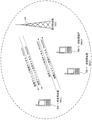
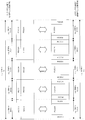
- FIG. 9 is a diagram for explaining a mobile communication system in which frequency bands are aggregated in the conventional technology.
- the frequency band used for downlink (DL) communication and the frequency band used for uplink (UL) communication as shown in FIG. 9 have the same bandwidth. It is also called aggregation (Symmetric carriergregaggregation).
- the base station apparatus and the mobile station apparatus can use a plurality of component carriers that are continuous and / or discontinuous frequency bands in a complex manner, thereby providing a wideband structure composed of a plurality of component carriers. Communication can be performed in the frequency band.
- DL system band and DL system bandwidth five frequency bands (hereinafter also referred to as DL system band and DL system bandwidth) used for downlink communication having a bandwidth of 100 MHz have five bandwidths of 20 MHz. It is shown that it is composed of downlink component carriers (DCC1: Downlink Component Carrier1, DCC2, DCC3, DCC4, DCC5).
- DCC1 Downlink Component Carrier1, DCC2, DCC3, DCC4, DCC5
- UL system band or UL system bandwidth the frequency band used for uplink communication with a bandwidth of 100 MHz
- UCC1 Uplink Component Carrier1, UCC2, UCC3, UCC4, UCC5
- each downlink component carrier includes a downlink physical channel such as a physical downlink control channel (hereinafter referred to as PDCCH: Physical Downlink Control Channel) and a physical downlink shared channel (hereinafter referred to as PDSCH: Physical Downlink Shared Channel).
- PDCCH Physical Downlink Control Channel
- PDSCH Physical Downlink Shared Channel
- the base station apparatus allocates downlink control information (DCI) for transmitting the PDSCH to the mobile station apparatus using the PDCCH, and transmits the PDSCH to the mobile station apparatus. That is, in FIG. 9, the base station apparatus can transmit up to five PDSCHs (which may be downlink transport blocks) to the mobile station apparatus in the same subframe.
- DCI downlink control information
- Each uplink component carrier has an uplink physical channel such as a physical uplink control channel (hereinafter PUCCH: Physical Uplink Control Channel) or a physical uplink shared channel (PUSCH: Physical Uplink Shared Channel). Is done.
- the mobile station apparatus transmits uplink control information (UCI: Uplink Control Information) to the base station apparatus using PUCCH and / or PUSCH.
- UCI Uplink Control Information
- the mobile station apparatus can transmit up to five PUSCHs (or uplink transport blocks may be used) in the same subframe to the base station apparatus.
- FIG. 10 is a diagram for explaining a mobile communication system in which asymmetric frequency bands are aggregated in the prior art.
- the base station apparatus and the mobile station apparatus have different frequency bands used for downlink communication and frequency bands used for uplink communication, and configure these frequency bands. It is possible to perform communication in a wide frequency band by using a component carrier that is a continuous and / or discontinuous frequency band.
- five downlink component carriers (DCC1, DCC2, DCC3, DCC4, DCC5) whose frequency band used for downlink communication having a bandwidth of 100 MHz is 20 MHz. And that the frequency band used for uplink communication with a bandwidth of 40 MHz is composed of two uplink component carriers (UCC1, UCC2) with a bandwidth of 20 MHz. Show.
- downlink / uplink physical channels are allocated to downlink / uplink component carriers, respectively, and the base station apparatus allocates PDSCH to the mobile station apparatus using PDCCH, and assigns PDSCH. Transmit to the mobile station device. That is, in FIG. 10, the base station apparatus can transmit up to five PDSCHs (which may be downlink transport blocks) to the mobile station apparatus in the same subframe.
- the mobile station apparatus transmits uplink control information to the base station apparatus using PUCCH and / or PUSCH.
- the mobile station apparatus can transmit up to two PUSCHs (may be uplink transport blocks) to the base station apparatus in the same subframe.
- the conventional technique has a problem that when the base station apparatus and the mobile station apparatus perform communication using a plurality of component carriers, radio resources are used inefficiently.
- a mobile station apparatus When a mobile station apparatus communicates with a base station apparatus using a plurality of component carriers, it is preferable to use an optimal uplink control information transmission method in a mobile communication system in which frequency bands are aggregated. On the other hand, the mobile station apparatus must ensure consistency with the uplink control information transmission method in the prior art.
- the base station apparatus performs, for the mobile station apparatus, an optimal uplink control information transmission method in a mobile communication system in which frequency bands are aggregated.
- the downlink control information must be instructed whether to perform the transmission method. That is, the base station apparatus and the mobile station apparatus use radio resources inefficiently when transmitting / receiving uplink control information.
- An object of the present invention is to provide a mobile communication system, a mobile station apparatus, a base station apparatus, and a communication method that can transmit and receive uplink control information.
- the mobile station apparatus of the present invention is a mobile station apparatus that transmits information indicating ACK or NACK for a transport block transmitted by the base station apparatus to the base station apparatus using a physical uplink shared channel.
- a unit for selecting information indicating the first ACK or NACK When transmitting information indicating the ACK or NACK for the transport block transmitted by one component carrier to the base station apparatus, a unit for selecting information indicating the first ACK or NACK, and a plurality of units When transmitting information indicating the ACK or NACK for the transport block transmitted on a component carrier to the base station apparatus, a unit for selecting information indicating a second ACK or NACK, and the selected first Information indicating ACK or NACK.
- the information indicating the second ACK or NACK which is, is characterized in that and a unit for transmitting to the base station device using the physical uplink shared channel.
- the mobile station apparatus of the present invention transmits information indicating ACK or NACK for the transport block transmitted by the base station apparatus to the base station apparatus using a physical uplink shared channel.
- a device for selecting a first arrangement method, and a plurality of components When transmitting information indicating the ACK or NACK for the transport block transmitted on a carrier to the base station apparatus, a unit that selects a second arrangement method, and the selected first arrangement method or the selection Information indicating the ACK or NACK using the second arrangement method described above.
- a unit for processing the information indicating the ACK or NACK is the processing, it is characterized by and a unit for transmitting to the base station device using the physical uplink shared channel.
- the base station apparatus of this invention receives the information which shows ACK or NACK with respect to the transport block transmitted to the mobile station apparatus from the said mobile station apparatus using a physical uplink shared channel.
- Indicates the first ACK or NACK Information indicating information or second ACK or NACK said selected is characterized in that and a unit for receiving from the mobile station device using the physical uplink shared channel.
- the base station apparatus of this invention receives the information which shows ACK or NACK with respect to the transport block transmitted to the mobile station apparatus from the said mobile station apparatus using a physical uplink shared channel.
- the information indicating the ACK or NACK treated Te is characterized by and a unit for receiving from the mobile station device using the physical uplink shared channel.
- the mobile communication system of the present invention is a mobile communication system in which a base station apparatus and a terminal apparatus communicate with each other, and the base station apparatus uses a single component carrier or a plurality of component carriers to transport the transport block.
- a unit for selecting information indicating a second ACK or NACK which is information indicating ACK or NACK for the transport block transmitted on a component carrier, and information indicating the selected first ACK or NACK or the selection
- a unit that transmits the information indicating the second ACK or NACK to the base station apparatus using a physical uplink shared channel If multiple A unit for selecting information indicating a second ACK or NACK, which is information indicating ACK or NACK for the transport block transmitted on a component carrier, and information indicating the selected first ACK or NACK or the selection And a unit that transmits the information indicating the second ACK or NACK to the base station apparatus using a physical uplink shared channel.
- the mobile communication system of the present invention is a mobile communication system in which a base station apparatus and a terminal apparatus communicate with each other, and the base station apparatus uses a single component carrier or a plurality of component carriers to transport the transport block.
- a unit that transmits to the mobile station apparatus, and the mobile station apparatus selects a first arrangement method when the base station apparatus transmits the transport block for the mobile station apparatus using one component carrier.
- a unit that selects a second arrangement method when the base station apparatus transmits the transport block for the mobile station apparatus using a plurality of component carriers, and the selected first arrangement method or the For the transport block using the selected second placement method A unit for processing information indicating CK or NACK, and a unit for transmitting the information indicating the processed ACK or NACK to the base station apparatus using the physical uplink shared channel. It is said.
- the communication method of this invention transmits the information which shows ACK or NACK with respect to the transport block transmitted by a base station apparatus to the said base station apparatus using a physical uplink shared channel.
- the information indicating the first ACK or NACK is selected.
- the information indicating the second ACK or NACK is selected, and the selected second Information indicating one ACK or NACK or the selected second Information indicating ACK or NACK, and transmits to the base station device using the physical uplink shared channel is characterized by.
- the communication method of this invention transmits the information which shows ACK or NACK with respect to the transport block transmitted by a base station apparatus to the said base station apparatus using a physical uplink shared channel.
- the first arrangement method is selected, and a plurality of components are transmitted.
- the second arrangement method is selected, and the selected first arrangement method or the selected first Processing the information indicating the ACK or NACK using the arrangement method of 2
- the information indicating the physical been the ACK or NACK, and transmits to the base station device using the physical uplink shared channel is characterized by.
- the base station apparatus and the mobile station apparatus perform communication by using a plurality of component carriers in combination, it is possible to efficiently transmit and receive uplink control information by using radio resources efficiently.
- FIG. 1 is a diagram illustrating a configuration example of a channel according to the embodiment of the present invention.
- the communication system according to the present invention includes a base station device 100 (downlink transmission device, uplink reception device, eNodeB, BS: Base Station, cell) and mobile station devices 200-1 to 200-3 (downlink reception device, uplink). It includes a link transmission device, a terminal device, UE: User ⁇ Equipment, MS: Mobile Station) (hereinafter, the mobile station devices 200-1 to 200-3 are collectively referred to as a mobile station device 200).
- the downlink physical channel includes a physical downlink control channel (PDCCH: Physical Downlink Control Channel), a physical downlink shared channel (PDSCH: Physical Downlink Shared Channel), and the like.
- the uplink physical channel includes a physical uplink shared channel (PUSCH: Physical Uplink Shared Channel), a physical uplink control channel (PUCCH: Physical Uplink Control Channel), and the like.
- the PDCCH is a channel used for notifying (designating) the mobile station apparatus 200 of PDSCH resource allocation, HARQ processing information for downlink data, PUSCH resource allocation, and the like.
- the PDCCH is composed of a plurality of control channel elements (CCE: Control Channel Element), and the mobile station apparatus 200 receives the PDCCH from the base station apparatus 100 by detecting the PDCCH composed of CCEs.
- CCE Control Channel Element
- This CCE is composed of a plurality of resource element groups (REG: Resource Element Group, also called mini-CCE) distributed in frequency and time domains.
- the resource element is a unit resource composed of one OFDM symbol (time component) and one subcarrier (frequency component).
- the REG represents a downlink reference signal in the frequency domain within the same OFDM symbol. Except for this, it is composed of four downlink resource elements that are continuous in the frequency domain.
- one PDCCH is composed of one, two, four, and eight CCEs in which numbers (CCE indexes) for identifying CCEs are consecutive.
- the PDCCH is encoded (Separate-Coding) separately for each mobile station apparatus 200 and for each type. That is, the mobile station apparatus 200 detects a plurality of PDCCHs, and acquires downlink or uplink resource allocation and other control information. Each PDCCH is assigned a CRC (Cyclic Redundancy Check) value, and the mobile station apparatus 200 performs a CRC check on each of the CCE sets in which the PDCCH may be configured. A successful PDCCH can be obtained. This is also referred to as blind decoding, and the range of the CCE set in which the mobile station apparatus 200 may configure the PDCCH that performs blind decoding is referred to as a search space (Search Space). The That is, mobile station apparatus 200 performs blind decoding on CCEs in the search area and detects PDCCH.
- CRC Cyclic Redundancy Check
- the mobile station apparatus 200 tries to search (detect) a PDCCH addressed to itself, and a plurality of mobile station apparatuses 200 try to search for a PDCCH and a common search area (CSS: Common Search Space).
- CCS Common Search Space
- the base station apparatus 100 can arrange
- the mobile station device 200 uses the PDSCH according to the resource allocation instructed by the PDCCH from the base station device 100 (hereinafter also referred to as a downlink signal). (Downlink data (downlink shared channel (DL-SCH)) and / or downlink control data (downlink control information)). That is, this PDCCH is a signal for performing resource allocation for the downlink (hereinafter also referred to as “downlink transmission permission signal” or “downlink grant”).
- DL-SCH downlink shared channel
- downlink control data downlink control information
- the mobile station device 200 uses the PUSCH according to the resource allocation instructed by the PDCCH from the base station device 100 to perform data (hereinafter, uplink signal).
- uplink signal Uplink data (uplink shared channel (UL-SCH)) and / or uplink control data (uplink control information))
- this PDCCH is a signal that permits data transmission on the uplink (hereinafter also referred to as “uplink transmission permission signal” or “uplink grant”).
- PDSCH is a channel used for transmitting downlink data (downlink shared channel: DL-SCH) or paging information (paging channel: PCH).
- the PMCH is a channel used for transmitting a multicast channel (MCH), and a downlink reference signal, an uplink reference signal, and a physical downlink synchronization signal are separately arranged.
- downlink data indicates transmission of user data
- DL-SCH is a transport channel.
- HARQ and dynamic adaptive radio link control are supported, and beamforming can be used.
- the DL-SCH supports dynamic resource allocation and semi-static resource allocation.
- the PUSCH is a channel mainly used for transmitting uplink data (uplink shared channel: UL-SCH). Moreover, when the base station apparatus 100 schedules the mobile station apparatus 200, uplink control information is also transmitted using PUSCH.
- This uplink control information includes feedback information based on the status (state) of the downlink propagation path (transmission channel, transmission path, communication path) and control information in HARQ (Hybrid Automatic Repeat reQuest).
- the feedback information is recommended transmission format information (implicit propagation path condition information) for the base station and information (explicit propagation path condition information) indicating the propagation path condition.
- the feedback information includes channel state information CSI (Channel State Information or Channel Statistical Information) indicating the downlink channel state, downlink channel quality identifier CQI (Channel Quality Indicator), and precoding.
- CSI Channel State Information or Channel Statistical Information
- CQI Channel Quality Indicator
- precoding Information indicating a matrix identifier PMI (Precoding Matrix Indicator) and a rank identifier RI (Rank Indicator) is included.
- control information in HARQ includes information indicating ACK (Acknowledgement) / NACK (Negative Acknowledgement) and / or information indicating DTX for the PDCCH and / or downlink transport block transmitted from the base station apparatus 100.
- the information indicating DTX is information indicating that the mobile station apparatus 200 has not been able to detect the PDCCH transmitted from the base station apparatus 100 (may be information indicating whether the PDCCH has been detected).
- the feedback information indicates information indicating a propagation path condition for a downlink signal transmitted from the mobile station apparatus 200 to the base station apparatus 100.
- the mobile station apparatus 200 transmits a downlink measurement reference signal (CSI-RS (Reference Signal), CRS (Cell-specific RS), base station apparatus 100 specific reference signal, cell specific reference) transmitted from the base station apparatus 100.
- CSI-RS Reference Signal
- CRS Cell-specific RS
- base station apparatus 100 specific reference signal cell specific reference
- the propagation path condition for the downlink signal is measured (calculated and generated) and transmitted (reported and fed back) to the base station apparatus 100 as feedback information.
- the reference signal is a signal (information) known to the base station apparatus 100 and the mobile station apparatus 200.
- the base station apparatus 100 can perform various adaptive controls on the mobile station apparatus 200 based on feedback information from the mobile station apparatus 200.
- CQI is information indicating a coding rate and a modulation scheme.
- Base station apparatus 100 can control the encoding process and the modulation process based on the CQI fed back from mobile station apparatus 200. By the adaptive control of the coding rate and the modulation method by the base station apparatus 100, optimal data transmission according to the reception quality in the mobile station apparatus 200 becomes possible.
- PMI is information indicating a precoding matrix (precoding weight, precoding vector).
- the base station apparatus 100 can control the precoding process based on the PMI fed back from the mobile station apparatus 200.
- the base station apparatus 100 can improve the reception quality in the mobile station apparatus 200 by adaptively controlling the precoding matrix.
- precoding is processing such as phase rotation and weighting processing for a signal transmitted from the transmission antenna of base station apparatus 100.
- RI is information indicating the number of spatial multiplexing (number of layers, number of ranks) of SDM (Space Division Multiplexing) using MIMO (Multiple Input Multiple Multiple Output).
- the base station apparatus 100 can control the layer mapping process in the base station apparatus 100 and the upper layer process for generating the codeword.
- the base station apparatus 100 adaptively controls the number of spatial multiplexing, optimal data transmission according to the reception quality in the mobile station apparatus 200 becomes possible. Further, when feedback information related to mapping to resources is also included, it is possible to control the resource element mapping processing in the base station apparatus 100.
- PMI can be divided into a plurality of types according to the data transmission method, purpose, application, and the like.
- PMI can be divided into PMI1 indicating a wideband precoding matrix W1 and PMI2 indicating a narrowband precoding matrix W2. That is, PMI includes PMI1 indicating a wideband precoding matrix W1 and PMI2 indicating a narrowband precoding matrix W2.
- the wideband precoding matrix W1 can be a precoding matrix in a system bandwidth or a frequency bandwidth constituting a component carrier.
- the narrowband precoding matrix W2 is a precoding matrix in a bandwidth that is the same as or narrower than the frequency bandwidth indicated by the wideband precoding matrix, for example, a bandwidth part composed of at least one resource block. (BW (Bandwidth) part) or a precoding matrix in a subband.
- PMI1 can be long-term (long interval) precoding information.
- PMI2 can be precoding information of a short term (short section).
- precoding processing based on wideband precoding information PMI1 and narrowband precoding information PMI2 and wideband precoding matrix W1 and PMI2 indicated by PMI1 will be described in more detail. To do.
- W1 and W2 are codebooks as A and B, respectively, and their indexes i and j are reported as PMI1 and PMI2.
- W1 and W2 are defined in 16 types of A (i) and B (j), respectively, and 4-bit PMI1 and PMI2 are reported as feedback information.
- F is a matrix of the size of the number of layers ⁇ the number of antenna ports
- a and B are matrices of a predetermined size.
- the matrix here is a concept including a vector or a scalar.
- a and B for example, any matrix uniquely determined by designating i and j as follows can be used.
- V1 and V2 are predetermined matrices composed of elements of 0 and 1
- Wi is a matrix specified by a predetermined codebook
- ⁇ j is a scalar specified by a predetermined codebook.
- Wi and ⁇ j are matrices specified by a predetermined codebook.
- Wi and ⁇ j are matrices specified by a predetermined codebook.
- U is a predetermined matrix
- I is a unit matrix
- Wi and ⁇ j are matrices specified by a predetermined codebook.
- K (X, Y) is a Kronecker product of the matrix X and the matrix Y
- XT is an operator representing a transposed matrix of the matrix X.
- a suitable precoder expressed using PMI1 and PMI2 can be expressed as a precoder that combines the precoder expressed by PMI1 and the precoder expressed by PMI2.
- the mobile station apparatus 200 uses the base station apparatus specific reference signal from the base station apparatus 100 to obtain information on the propagation path condition with the base station apparatus 100. provide feedback. At that time, the amount of information can be reduced by using various methods such as eigenvalue decomposition and quantization.
- the mobile station apparatus 200 is controlled using the information on the fed back propagation path condition. For example, the base station apparatus 100 can determine the coding rate, the modulation scheme, the number of layers, and the precoding matrix so that the mobile station apparatus 200 can receive optimally based on the fed back information, Various methods can be used.
- uplink data indicates transmission of user data, for example, and UL-SCH is a transport channel.
- UL-SCH HARQ and dynamic adaptive radio link control are supported, and beamforming can be used.
- UL-SCH supports dynamic resource allocation and quasi-static resource allocation.
- radio resource control signals exchanged between the base station apparatus 100 and the mobile station apparatus 200 hereinafter referred to as “RRC signaling: Radio Resource”.
- RRC signaling Radio Resource
- Control Signaling
- MAC Medium Access Control
- the base station device 100 and the mobile station device 200 transmit and receive RRC signaling in an upper layer (Radio Resource Control layer).
- the base station apparatus 100 and the mobile station apparatus 200 transmit and receive the MAC control element in an upper layer (medium access control (MAC: Medium Access Control) layer).
- MAC Medium Access Control
- the PUCCH is a channel used for transmitting uplink control information.
- the uplink control information is, for example, propagation path condition information CSI indicating a downlink propagation path condition, downlink propagation path quality identifier CQI, precoding matrix identifier PMI, rank identifier RI, mobile station
- the device 200 includes a scheduling request (SR: “Scheduling” Request) for requesting allocation of resources for transmitting uplink data (requesting transmission on UL-SCH), and control information in HARQ.
- SR “Scheduling” Request
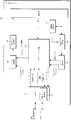
- FIG. 2 is a block diagram showing a schematic configuration of the base station apparatus 100 according to the embodiment of the present invention.
- the base station apparatus 100 includes a data control unit 101, a transmission data modulation unit 102, a radio unit 103, a scheduling unit 104, a propagation path estimation unit 105, a reception data demodulation unit 106, a data extraction unit 107, A layer 108 and an antenna 109 are included.
- the radio unit 103, the scheduling unit 104, the propagation path estimation unit 105, the reception data demodulation unit 106, the data extraction unit 107, the upper layer 108 and the antenna 109 constitute a reception unit, and the data control unit 101 and the transmission data modulation unit 102
- the radio unit 103, the scheduling unit 104, the upper layer 108, and the antenna 109 constitute a transmission unit.
- the antenna 109, the radio unit 103, the propagation path estimation unit 105, the reception data demodulation unit 106, and the data extraction unit 107 perform processing on the uplink physical layer.
- the antenna 109, the radio unit 103, the transmission data modulation unit 102, and the data control unit 101 perform downlink physical layer processing.
- the data control unit 101 receives a transport channel from the scheduling unit 104.
- the data control unit 101 maps the transport channel and the signal and channel generated in the physical layer to the physical channel based on the scheduling information input from the scheduling unit 104.
- Each piece of data mapped as described above is output to transmission data modulation section 102.
- the transmission data modulation unit 102 modulates transmission data into an OFDM signal.
- the transmission data modulation unit 102 performs data modulation, coding, and coding on the data input from the data control unit 101 based on the scheduling information from the scheduling unit 104 and the modulation scheme and coding scheme corresponding to each PRB.
- Input signal serial / parallel conversion, IFFT (Inverse Fourier Transform) processing, CP (Cyclic Prefix) insertion, filtering, and other signal processing are performed to generate transmission data, and to the wireless unit 103 Output.
- the scheduling information includes downlink physical resource block PRB (Physical Resource Block) allocation information, for example, physical resource block position information composed of frequency and time, and the modulation scheme and encoding corresponding to each PRB.
- the rate includes, for example, information such as a modulation scheme: 16QAM and a coding rate: 2/3 coding rate.
- the radio unit 103 up-converts the modulation data input from the transmission data modulation unit 102 to a radio frequency to generate a radio signal, and transmits the radio signal to the mobile station apparatus 200 via the antenna 109. Also, the radio section 103 receives an uplink radio signal from the mobile station apparatus 200 via the antenna 109, down-converts it into a baseband signal, and converts the received data into a propagation path estimation section 105 and a received data demodulation section. 106.
- the scheduling unit 104 performs processing of a medium access control (MAC: Medium Access Control) layer.
- the scheduling unit 104 performs mapping between logical channels and transport channels, downlink and uplink scheduling (HARQ processing, selection of transport format, etc.) and the like. Since the scheduling unit 104 controls the processing units of each physical layer in an integrated manner, the scheduling unit 104, the antenna 109, the radio unit 103, the propagation path estimation unit 105, the reception data demodulation unit 106, the data control unit 101, the transmission data There is an interface between the modulation unit 102 and the data extraction unit 107 (not shown).
- MAC Medium Access Control
- the scheduling unit 104 receives feedback information (uplink feedback information (CSI, CQI, PMI, RI), ACK / NACK information for downlink data, etc.) received from the mobile station apparatus 200, each movement Downlink transport format (transmission form, ie, physical resource block) for modulating each data based on PRB information usable by station apparatus 200, buffer status, scheduling information input from higher layer 108, and the like Allocation processing, modulation scheme and coding scheme), HARQ retransmission control, and scheduling information used for downlink.
- the scheduling information used for downlink scheduling is output to the data control unit 101.
- the scheduling unit 104 estimates an uplink measurement propagation path condition output from the propagation path estimation unit 105, a resource allocation request from the mobile station apparatus 200, and each mobile station apparatus 200.
- Uplink transport format transmission form, ie, physical resource block allocation and modulation scheme and code
- Scheduling information used for uplink scheduling and generation of scheduling information Scheduling information used for uplink scheduling is output to the data control unit 101.
- the scheduling unit 104 maps the downlink logical channel input from the higher layer 108 to the transport channel, and outputs it to the data control unit 101.
- the scheduling unit 104 processes the control data and the transport channel acquired in the uplink input from the data extraction unit 107 as necessary, maps them to the uplink logical channel, and outputs them to the upper layer 108. To do.
- the propagation path estimation unit 105 estimates an uplink demodulation propagation path condition from an uplink demodulation reference signal (DMRS: Demodulation Reference Signal, DRS: Dedicated RS) for demodulation of the uplink data, and the estimation The result is output to reception data demodulation section 106. Further, in order to perform uplink scheduling, a channel state for uplink measurement (for adaptive control) is estimated from an uplink measurement reference signal (SRS: Sounding Reference Signal), and the estimation result is used as a scheduling unit 104. Output to.
- DMRS Demodulation Reference Signal
- DRS Dedicated RS
- SRS Sounding Reference Signal
- the uplink demodulation reference signal is an independent reference signal for each data (layer, rank) spatially multiplexed by the mobile station apparatus 200, and the base station apparatus 100 determines the propagation path condition for each spatially multiplexed data. Is estimated. Further, the uplink measurement reference signal is an independent reference signal for each antenna port of the mobile station apparatus 200, and the base station apparatus 100 estimates a propagation path condition for each antenna port.
- the reception data demodulation unit 106 also serves as a DFT-Spread-OFDM demodulation unit that demodulates reception data modulated into a DFT-Spread-OFDM (SC-FDMA) signal.
- the received data demodulation unit 106 performs DFT conversion, subcarrier mapping, IFFT conversion on the modulated data input from the radio unit 103 based on the uplink channel condition estimation result input from the channel estimation unit 105.
- Signal processing such as filtering is performed, demodulation processing is performed, and the result is output to the data extraction unit 107.
- the data extraction unit 107 confirms the correctness of the data input from the reception data demodulation unit 106 and outputs a confirmation result (positive signal ACK / negative signal NACK) to the scheduling unit 104.
- the data extraction unit 107 separates the data input from the reception data demodulation unit 106 into a transport channel and physical layer control data, and outputs the data to the scheduling unit 104.
- the separated control data includes propagation path status information CSI notified from the mobile station apparatus 200, downlink propagation path quality identifier CQI, precoding matrix identifier PMI, rank identifier RI, control information in HARQ, Includes scheduling requests.
- the upper layer 108 performs processing of a packet data integration protocol (PDCP: Packet Data Convergence Protocol) layer, a radio link control (RLC: Radio Link Control) layer, and a radio resource control (RRC: Radio Resource Control) layer.
- PDCP Packet Data Convergence Protocol
- RLC Radio Link Control
- RRC Radio Resource Control
- the upper layer 108 integrates and controls the processing units in the lower layer.
- the upper layer 108 has a radio resource control unit 110 (also referred to as a control unit).
- the radio resource control unit 110 also manages various setting information, system information, paging control, communication state management of each mobile station device 200, mobility management such as handover, and buffer status for each mobile station device 200. Management, management of unicast and multicast bearer connection settings, management of mobile station identifiers (UEID), etc.
- Upper layer 108 exchanges information with another base station apparatus 100 and information with an upper node.
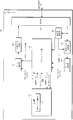
- FIG. 3 is a block diagram showing a schematic configuration of the mobile station apparatus 200 according to the embodiment of the present invention.
- the mobile station apparatus 200 includes a data control unit 201, a transmission data modulation unit 202, a radio unit 203, a scheduling unit 204, a propagation path estimation unit 205, a reception data demodulation unit 206, a data extraction unit 207, A layer 208 and an antenna 209 are included.
- the data control unit 201, transmission data modulation unit 202, radio unit 203, scheduling unit 204, upper layer 208, and antenna 209 constitute a transmission unit, and the radio unit 203, scheduling unit 204, propagation path estimation unit 205, received data
- the demodulating unit 206, the data extracting unit 207, the upper layer 208, and the antenna 209 constitute a receiving unit.
- the data control unit 201, the transmission data modulation unit 202, and the radio unit 203 perform processing of the uplink physical layer.
- the radio unit 203, the propagation path estimation unit 205, the received data demodulation unit 206, and the data extraction unit 207 perform downlink physical layer processing.
- the data control unit 201 receives the transport channel from the scheduling unit 204.
- the transport channel and the signal and channel generated in the physical layer are mapped to the physical channel based on the scheduling information input from the scheduling unit 204.
- Each piece of data mapped in this way is output to transmission data modulation section 202.
- the transmission data modulation unit 202 modulates transmission data into a DFT-Spread-OFDM (SC-FDMA) signal.
- the transmission data modulation unit 202 performs data modulation, DFT (Discrete Fourier Transform) processing, subcarrier mapping, IFFT (Inverse Fast Fourier Transform) processing, CP insertion, filtering, and other signals on the data input from the data control unit 201. Processing is performed, transmission data is generated, and output to the wireless unit 203.
- the radio unit 203 up-converts the modulation data input from the transmission data modulation unit 202 to a radio frequency to generate a radio signal, and transmits the radio signal to the base station apparatus 100 via the antenna 209.
- Radio section 203 receives a radio signal modulated with downlink data from base station apparatus 100 via antenna 209, down-converts it to a baseband signal, and converts the received data into a propagation path estimation section. 205 and the received data demodulation section 206.
- the scheduling unit 204 performs processing of a medium access control (MAC: Medium Access Control) layer.
- the scheduling unit 204 performs mapping between logical channels and transport channels, downlink and uplink scheduling (HARQ processing, transport format selection, etc.), and the like. Since the scheduling unit 204 controls the processing units of each physical layer in an integrated manner, the scheduling unit 204, the antenna 209, the data control unit 201, the transmission data modulation unit 202, the propagation path estimation unit 205, the reception data demodulation unit 206, There is an interface between the data extraction unit 207 and the wireless unit 203 (not shown).
- MAC Medium Access Control
- the scheduling unit 204 performs reception control of transport channels, physical signals, and physical channels based on scheduling information (transport format and HARQ retransmission information) from the base station apparatus 100 and the upper layer 208, and the like. Scheduling information used for HARQ retransmission control and downlink scheduling is generated. The scheduling information used for downlink scheduling is output to the data control unit 201.
- scheduling information transport format and HARQ retransmission information
- the scheduling unit 204 receives the uplink buffer status input from the higher layer 208 and the uplink scheduling information (transport format and HARQ retransmission) from the base station apparatus 100 input from the data extraction unit 207. Information), and scheduling processing for mapping the uplink logical channel input from the upper layer 208 to the transport channel and the uplink scheduling based on the scheduling information input from the upper layer 208, etc. Scheduling information to be generated is generated. Note that the information notified from the base station apparatus 100 is used for the uplink transport format. The scheduling information is output to the data control unit 201.
- the uplink scheduling information transport format and HARQ retransmission
- the scheduling unit 204 maps the uplink logical channel input from the higher layer 208 to the transport channel, and outputs it to the data control unit 201. Also, the scheduling unit 204 includes downlink channel state information CSI input from the channel estimation unit 205, downlink channel quality identifier CQI, precoding matrix identifier PMI, rank identifier RI, and data extraction unit 207. The check result of the CRC check input from is also output to the data control unit 201. In addition, the scheduling unit 204 processes the control data and the transport channel acquired in the downlink input from the data extraction unit 207 as necessary, maps them to the downlink logical channel, and outputs them to the upper layer 208. To do.
- the propagation path estimation unit 205 estimates a downlink demodulation channel condition from a downlink demodulation reference signal (DMRS, mobile station apparatus specific reference signal, Precoded RS) for demodulation of downlink data, The estimation result is output to reception data demodulation section 206. Also, the propagation path estimation unit 205 uses the downlink estimation reference signal (CSI-RS) to estimate the downlink in order to notify (feed back) the downlink propagation path condition estimation result to the base station apparatus 100. Estimating the propagation path situation (for feedback), and using the estimation result as the downlink propagation path situation information CSI, downlink propagation path quality identifier CQI, precoding matrix identifier PMI, rank identifier RI, and scheduling unit To 204.
- CSI-RS downlink estimation reference signal
- the downlink demodulation reference signal is an independent reference signal for each data (layer, rank) spatially multiplexed by the base station, and the mobile station apparatus 200 estimates a propagation path condition for each spatially multiplexed data.
- the downlink measurement reference signal is an independent reference signal for each antenna port of the base station, and the mobile station apparatus 200 estimates a propagation path condition for each antenna port of the base station.
- Received data demodulation section 206 demodulates received data modulated by the OFDM method.
- the received data demodulation unit 206 performs demodulation processing on the modulated data input from the radio unit 203 based on the downlink propagation path state estimation result input from the propagation path estimation unit 205, and the data extraction unit 207. Output to.
- the data extracting unit 207 performs a CRC check on the data input from the received data demodulating unit 206, confirms correctness and outputs a confirmation result (acknowledgment ACK / negative response NACK) to the scheduling unit 204.
- the data extraction unit 207 separates the data input from the reception data demodulation unit 206 into transport channel and physical layer control data, and outputs the data to the scheduling unit 204.
- the separated control data includes scheduling information such as downlink or uplink resource allocation and uplink HARQ control information.
- the upper layer 208 performs processing of a packet data integration protocol (PDCP: Packet Data Convergence Protocol) layer, a radio link control (RLC: Radio Link Control) layer, and a radio resource control (RRC: Radio Resource Control) layer. Since the upper layer 208 controls the processing units of the lower layer in an integrated manner, the upper layer 208, the scheduling unit 204, the antenna 209, the data control unit 201, the transmission data modulation unit 202, the propagation path estimation unit 205, the received data demodulation unit There is an interface between the unit 206, the data extraction unit 207, and the radio unit 203 (not shown).
- PDCP Packet Data Convergence Protocol
- RLC Radio Link Control
- RRC Radio Resource Control
- the upper layer 208 has a radio resource control unit 210 (also referred to as a control unit).
- the radio resource control unit 210 manages various setting information, system information, paging control, own station communication status, mobility management such as handover, buffer status management, unicast and multicast bearer connection setting. Management and management of mobile station identifier (UEID).
- UEID mobile station identifier
- the base station apparatus 100 sets a specific downlink component carrier in the mobile station apparatus 200, and the mobile station apparatus 200 only performs PDSCH in a specific downlink component carrier by the base station apparatus 100.
- the first allocation method mapping method, multiplexing method, rearrangement method, interleaving method
- the base station apparatus 100 selects a channel other than a specific downlink component carrier.
- the second arrangement method mapping method, multiplexing method, rearrangement method, interleaving method for the uplink control information is selected.
- the mobile station apparatus 200 switches (selects) the arrangement method for the uplink control information according to the PDSCH scheduling by the base station apparatus 100. Further, the base station apparatus 100 receives, from the mobile station apparatus 200, uplink control information arranged by the arrangement method switched by the mobile station apparatus 200 in accordance with PDSCH scheduling for the mobile station apparatus 200.
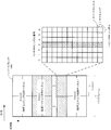
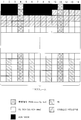
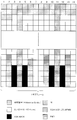
- FIG. 4 is a diagram showing a resource configuration in the uplink according to the present embodiment.
- each horizontal axis represents time, and the vertical axis represents frequency.
- uplink resources include a physical uplink control channel (PUCCH) mainly used for transmitting control information, and a physical uplink for each mobile station device 200 to mainly transmit data.
- PUCCH physical uplink control channel
- PUSCH link shared channel
- RB resource blocks
- the number of resource blocks in the frequency direction depends on the system bandwidth.
- the time unit occupied by one resource block is called one slot, and the combination of two is called one subframe.
- the PUSCH is allocated to the mobile station apparatus 200 in resource block units in which two slots are paired.
- FIG. 4 shows a configuration within one resource block of PUSCH. That is, FIG. 4 shows an enlarged view of one PUSCH resource block.
- one resource block is composed of seven SC-FDMA symbols (corresponding to one slot) and 12 subcarriers in the frequency direction, and is a minimum resource unit composed of one SC-FDMA symbol and one subcarrier.
- the modulation symbols arranged in the resource elements are converted into time domain signals by processing such as FFT (FastFFourier Transformation) in units of SC-FDMA symbols, and then transmitted from the mobile station apparatus 200 to the base station apparatus 100.
- FFT FastFFourier Transformation
- a DRS for propagation path estimation at the time of demodulation is arranged in the third SC-FDMA symbol.
- the frequency band is defined by the bandwidth (Hz), but may be defined by the number of resource blocks (RB) configured by frequency and time. That is, the bandwidth may be defined by the number of resource blocks. Also, the bandwidth and the number of resource blocks can be defined by the number of subcarriers.
- the component carrier in the present embodiment is used in combination in a mobile communication system having a wide frequency band (or a system band) when the base station apparatus 100 and the mobile station apparatus 200 perform communication (narrow band).
- Frequency band The base station apparatus 100 and the mobile station apparatus 200 have a wide frequency band (for example, a bandwidth of 100 MHz) by aggregating a plurality of component carriers (for example, five frequency bands having a bandwidth of 20 MHz). Frequency band) and using a plurality of these component carriers in combination enables high-speed data communication.
- a component carrier is a frequency band (for example, a frequency band with a bandwidth of 20 MHz) that constitutes this wide frequency band (for example, a frequency band with a bandwidth of 100 MHz). Show.
- the component carrier may indicate the (center) carrier frequency of each of these (narrow band) frequency bands. That is, the downlink component carrier has a partial band (width) in a frequency band that can be used when the base station apparatus 100 and the mobile station apparatus 200 transmit and receive downlink information, and the uplink component carrier The carrier has a partial band (width) in a frequency band that can be used when the base station apparatus 100 and the mobile station apparatus 200 transmit and receive uplink information.
- the component carrier may be defined as a unit in which a specific physical channel (for example, PDCCH, PUCCH, etc.) is configured.
- the component carrier may be arranged in a continuous frequency band or may be arranged in a discontinuous frequency band, and the base station apparatus 100 and the mobile station apparatus 200 have a continuous and / or discontinuous frequency band.
- the frequency band used for downlink communication constituted by component carriers and the frequency band used for uplink communication need not have the same bandwidth, and the base station apparatus 100 and the mobile station apparatus 200 Thus, communication can be performed using a combination of downlink frequency bands and uplink frequency bands having different bandwidths constituted by component carriers (asymmetric frequency band aggregation described above).
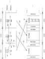
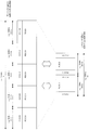
- FIG. 5 is a diagram illustrating an example of a mobile communication system to which the first embodiment can be applied.
- the first embodiment can be applied to any mobile communication system in which symmetric frequency band aggregation and asymmetric frequency band aggregation are performed.
- the following description describes only about the one part component carrier expanded as an example, of course, the same embodiment is applicable also to all the component carriers.
- FIG. 5 shows three downlink component carriers (DCC1, DCC2, DCC3) as an example for explaining the first embodiment. Also, three uplink component carriers (UCC1, UCC2, UCC3) are shown.
- the base station apparatus 100 can allocate (schedule) PDSCH (s) in the same subframe using PDCCH (s) in a downlink component carrier. .
- the base station apparatus 100 can assign a PDSCH in the same component carrier as the component carrier in which the PDCCH is arranged.
- the allocation 311 indicated by the solid line indicates that the base station apparatus 100 assigns the PDSCH in DCC1 using the PDCCH 301 (the PDCCH indicated by hatching) in DCC1.
- an allocation 312 indicated by a solid line indicates that the base station apparatus 100 uses the PDCCH 302 (PDCCH indicated by a grid line) in the DCC 2 to allocate the PDSCH in the DCC 2.
- the allocation 313 indicated by the solid line indicates that the base station apparatus 100 uses the PDCCH 303 (PDCCH indicated by the network line) in the DCC 3 to allocate the PDSCH in the DCC 3.
- the base station apparatus 100 can allocate PDSCH in the same or different component carrier where the PDCCH is arranged.
- the base station device 100 includes the component carrier indication field (CIF: Component carrier Indicator Field, for example, an information field represented by 3 bits) in the PDCCH, and transmits the PDCCH to the mobile station device 200.
- PDSCH in the same or different component carrier can be allocated.
- base station apparatus 100 transmits a component carrier indication field that indicates a component carrier in which PDSCH to be allocated using PDCCH is allocated, included in PDCCH, and is the same as or different from the component carrier in which PDCCH is allocated.
- the PDSCH in the component carrier can be assigned to the mobile station apparatus 200.
- the component carrier indication field included in the PDCCH transmitted from the base station apparatus 100 indicates which value, which component carrier the PDSCH is allocated to is defined in advance.
- the information is known among the mobile station devices 200.
- the base station apparatus 100 includes the component carrier indication field indicating a specific value (for example, the information field represented by 3 bits indicates “000”) in the PDCCH, and transmits it to the mobile station apparatus 200.
- PDSCH in the same component carrier as the component carrier in which PDCCH is arranged can be allocated to mobile station apparatus 200.
- the base station apparatus 100 transmits a PDCCH including a component carrier instruction field indicating a value other than a specific value (for example, an information field represented by 3 bits indicating other than “000”).
- PDSCH in a component carrier different from the arranged component carrier can be allocated to mobile station apparatus 200.
- the allocation 321 indicated by a dotted line indicates that the base station apparatus 100 allocates the PDSCH in DCC2 by using the PDCCH 301 (PDCCH indicated by hatching) in DCC1.
- the assignment 322 indicated by the dotted line indicates that the base station apparatus 100 assigns the PDSCH in the DCC 1 using the PDCCH 302 (PDCCH indicated by the grid line) in the DCC 2.
- the allocation 323 indicated by the dotted line indicates that the base station apparatus 100 allocates the PDSCH in the DCC 3 using the PDCCH 303 (PDCCH indicated by the network line) including the component carrier indication field in the DCC 3. Has been.
- the base station apparatus 100 can set information indicating whether or not to include a component carrier instruction field in the PDCCH for each mobile station apparatus 200.
- the base station apparatus 100 can set the information indicating whether or not to include the component carrier indication field in the PDCCH in the RRC signaling and set it in the mobile station apparatus 200.
- the base station apparatus 100 can set the information which shows whether a component carrier instruction
- the base station apparatus 100 can set information indicating whether or not to include a component carrier instruction field in the PDCCH in the RRC signaling for each component carrier and set it in the mobile station apparatus 200.
- the base station apparatus 100 transmits a downlink transport block to the mobile station apparatus 200 using the PDSCH assigned by the PDCCH (it can also be said to transmit PDSCH). For example, the base station apparatus 100 transmits (up to three) downlink transport blocks to the mobile station apparatus 200 in the same subframe using the PDSCH assigned by each of the PDCCHs in the DCC1, DCC2, and DCC3. be able to.
- the base station apparatus 100 can set a specific downlink component carrier for the mobile station apparatus 200.
- the base station apparatus 100 can set a specific downlink component carrier in the mobile station apparatus 200 using broadcast information (broadcast information, for example, SIB: System Information Block).
- broadcast information for example, SIB: System Information Block
- the base station apparatus 100 can set a specific downlink component carrier to the mobile station apparatus 200 in a cell-specific manner using broadcast information.
- the base station apparatus 100 can set a specific downlink component carrier in the mobile station apparatus 200 using RRC signaling.
- the base station apparatus 100 can set a specific downlink component carrier for the mobile station apparatus 200 to be specific to the mobile station apparatus (UE-specifically) using RRC signaling.
- the base station apparatus 100 can set a certain downlink component carrier to the mobile station apparatus 200 semi-statically using RRC signaling.
- the base station apparatus 100 can set the correspondence (link, linking) between the downlink component carrier and the uplink component carrier for the mobile station apparatus 200.
- the base station apparatus 100 moves the correspondence between the downlink component carrier and the uplink component carrier using broadcast information (broadcast information, eg, SIB: System Information Block) broadcast on each downlink component carrier. It can be set in the station device 200.
- the base station apparatus 100 can set the correspondence between the downlink component carrier and the uplink component carrier in the mobile station apparatus 200 in a cell-specific manner using broadcast information broadcast on each downlink component carrier. it can.
- the base station apparatus 100 can set the correspondence between the downlink component carrier and the uplink component carrier in the mobile station apparatus 200 using RRC signaling.
- the base station apparatus 100 can set the correspondence between the downlink component carrier and the uplink component carrier to the mobile station apparatus 200 using the RRC signaling.
- the base station apparatus 100 can set the correspondence between the downlink component carrier and the uplink component carrier to the mobile station apparatus 200 semi-statically using RRC signaling.
- the base station apparatus 100 sets the correspondence between a specific downlink component carrier and a specific uplink component carrier in the mobile station apparatus 200 using the broadcast information. Also, the base station apparatus 100 sets, in the mobile station apparatus 200, the correspondence between a specific downlink component carrier and a specific uplink component carrier in a cell-specific manner using broadcast information.
- the base station apparatus 100 sets the correspondence between a specific downlink component carrier and a specific uplink component carrier in the mobile station apparatus 200 using RRC signaling. Also, the base station apparatus 100 uses the RRC signaling to set, in the mobile station apparatus 200, a correspondence between a specific downlink component carrier and a specific uplink component carrier specific to the mobile station apparatus 200. Moreover, the base station apparatus 100 sets the correspondence of a certain downlink component carrier and a certain uplink component carrier to the mobile station apparatus 200 semi-statically using RRC signaling.
- the base station apparatus 100 can set a specific uplink component carrier as an uplink component carrier corresponding to a specific downlink component carrier for the mobile station apparatus 200. That is, the base station apparatus 100 sets a specific downlink component carrier for the mobile station apparatus 200, and the mobile station apparatus 200 specifies an uplink component carrier corresponding to a specific downlink component carrier. As an uplink component carrier.
- the base station apparatus 100 can associate DCC 1 and UCC 3 as indicated by a link 331. Further, the base station apparatus 100 can associate DCC2 and UCC1 as indicated by a link 332. Further, the base station apparatus 100 can associate DCC3 and UCC2 as indicated by a link 333.
- a specific downlink component carrier set by the base station apparatus 100 is also referred to as a primary downlink component carrier (PDCC).
- PDCC primary downlink component carrier
- SDCC Secondary Downlink Component Carrier
- a specific uplink component carrier recognized by the mobile station apparatus 200 as an uplink component carrier corresponding to a specific downlink component carrier is also referred to as a primary uplink component carrier (PUCC: Primary-Uplink-Component-Carrier). Call it.
- An uplink component carrier other than a specific uplink component carrier is also referred to as a secondary uplink component carrier (SUCC: SecondarySecondLink Component Carrier).
- the mobile station apparatus 200 when the base station apparatus 100 sets DCC1 as PDCC for the mobile station apparatus 200, the mobile station apparatus 200 recognizes UCC3 as PUCC and recognizes UCC1 and UCC2 as SUCC.
- base station apparatus 100 sets DCC2 as PDCC for mobile station apparatus 200 mobile station apparatus 200 recognizes UCC1 as PUCC, and recognizes UCC2 and UCC3 as SUCC.
- base station apparatus 100 sets DCC3 as PDCC for mobile station apparatus 200 mobile station apparatus 200 recognizes UCC2 as PUCC, and recognizes UCC1 and UCC3 as SUCC.
- base station apparatus 100 sets DCC2 as PDCC and UCC1 corresponding to DCC2 as PUCC for mobile station apparatus 200.
- the mobile station apparatus 200 uses the PUSCH assigned (scheduled) by the PDCCH (also referred to as an uplink transmission permission signal) transmitted from the base station apparatus 100, and uses the uplink transport block (UL -SCH) to base station apparatus 100. That is, the mobile station apparatus 200 arranges an uplink transport block (UL-SCH) in the allocated resource according to the resource allocation information for the PUSCH included in the PDCCH transmitted from the base station apparatus 100, and the base station apparatus 100. Send to. For example, the mobile station apparatus 200 transmits (up to three) uplink transport blocks (UL-SCH) to the base station apparatus 100 in the same subframe using PUSCH in UCC1, UCC2, and UCC3. be able to.
- the PDCCH also referred to as an uplink transmission permission signal
- the mobile station apparatus 200 transmits uplink control information to the base station apparatus 100 using PUCCH. That is, mobile station apparatus 200 transmits uplink control information to base station apparatus 100 using PUCCH in UCC1 (PUCC) corresponding to DCC2 set as PDCC by base station apparatus 100.
- PUCCH UCC1
- the mobile station apparatus 200 arranges uplink control information on the PUSCH and transmits it to the base station apparatus 100.
- the mobile station apparatus 200 arranges uplink control information on the PUSCH in UCC1 and transmits the uplink control information to the base station apparatus 100.
- the mobile station apparatus 200 arranges uplink control information on PUSCH in UCC2 and transmits it to base station apparatus 100.
- the PUSCH in UCC3 is scheduled by the base station apparatus 100
- the mobile station apparatus 200 arranges uplink control information on the PUSCH in UCC3 and transmits the uplink control information to the base station apparatus 100.
- base station apparatus 100 schedules PUSCH 341 in UCC3 for mobile station apparatus 200, and mobile station apparatus 200 arranges uplink control information in PUSCH 341 in UCC3 and transmits it to base station apparatus 100. It shows that.
- the mobile station apparatus 200 when a plurality of PUSCHs are scheduled in the same subframe by the base station apparatus 100, the mobile station apparatus 200 arranges uplink control information in any one of the plurality of PUSCHs and transmits it to the base station apparatus 100. To do. For example, when a plurality of PUSCHs are scheduled in the same subframe by the base station apparatus 100, the mobile station apparatus 200 can transmit uplink control information to the PUSCH in the PUCC and transmit it to the base station apparatus 100. . For example, when the PUSCH in UCC1, UCC2, and UCC3 is scheduled in the same subframe by the base station apparatus 100, the mobile station apparatus 200 arranges uplink control information in the PUSCH in UCC1 and transmits it to the base station apparatus 100. can do.
- both the uplink control information and the UL-SCH are arranged on the PUSCH and transmits to the base station apparatus 100. be able to.
- the mobile station apparatus 200 can transmit the HARQ control information and the UL-SCH together to the PUSCH scheduled by the base station apparatus 100 together with the PUSCH scheduled by the base station apparatus 100. That is, the mobile station apparatus 200 receives an ACK for a plurality of downlink transport blocks (or PDSCHs) transmitted in the same subframe using a plurality of downlink component carriers on the PUSCH scheduled by the base station apparatus 100. Information indicating / NACK and UL-SCH can be arranged and transmitted to base station apparatus 100.
- the mobile station apparatus 200 arranges both feedback information and UL-SCH in the PUSCH scheduled by the base station apparatus 100 and transmits the PUSCH to the base station apparatus 100.
- the mobile station apparatus 200 can transmit all or part of RI, CQI, and PMI together with UL-SCH to the PUSCH scheduled by the base station apparatus 100 and transmit it to the base station apparatus 100.
- the mobile station apparatus 200 can switch (select) the arrangement method for the uplink control information according to the PDSCH scheduling by the base station apparatus 100.
- the arrangement method of the uplink control information by the mobile station apparatus 200 indicates an arrangement method when the mobile station apparatus 200 arranges the uplink control information in the SC-FDMA symbol. That is, when PUSCH is scheduled by base station apparatus 100, mobile station apparatus 200 arranges uplink control information in SC-FDMA symbols, performs DFT processing for each SC-FDMA symbol, and converts it into a frequency domain signal. After the conversion, it is arranged on the PUSCH scheduled in the base station apparatus 100.
- the PUSCH is subjected to IFFT processing by a prescribed number of FFT points (for example, 2048), converted into a time domain signal, and then a cyclic prefix (guard interval) is added to each SC-FDMA symbol. It is transmitted to base station apparatus 100 as an SC-FDMA signal.
- FFT points for example, 2048
- guard interval a cyclic prefix
- the mobile station device 200 defines a matrix having a size equivalent to the size of PUSCH (PUSCH resource consisting of a time domain and a frequency domain) scheduled by the base station device 100, and in the defined matrix, Uplink control information is arranged.
- PUSCH PUSCH resource consisting of a time domain and a frequency domain
- the mobile station apparatus 200 performs DFT processing on this matrix and converts it to a frequency domain signal, and then arranges information after DFT on the PUSCH scheduled in the base station apparatus 100.
- the arrangement method of uplink control information by the mobile station device 200 indicates a method when the mobile station device 200 arranges uplink control information in a defined matrix.
- the arrangement method switched by the mobile station apparatus 200 is also referred to as a first arrangement method and a second arrangement method.
- the arrangement of the uplink control information is an arrangement of signals before performing the DFT process, and includes a case where a multiplexing process and a rearrangement process (interleaving process) are performed and as a result arranged.
- multiple processing of CQI and / or PMI and UL-SCH can also be set as an arrangement process (arrangement method).
- rearrangement processing of control information and UL-SCH in RI or HARQ can be an arrangement process (arrangement method).
- the mobile station device 200 switches the arrangement method for the uplink control information according to the PDSCH scheduling by the base station device 100.
- the mobile station apparatus 200 transmits control information in HARQ for the PDSCH (which may be a downlink transport block) transmitted by the base station apparatus 100
- PDSCH which may be a downlink transport block
- Control information in HARQ is arranged on PUSCH and transmitted to base station apparatus 100.
- the mobile station apparatus 200 can arrange both HARQ control information and UL-SCH on the PUSCH scheduled by the base station apparatus 100 and transmit it to the base station apparatus 100. Moreover, the mobile station apparatus 200 can arrange
- the mobile station apparatus 200 arranges the uplink control information using the first arrangement method. That is, when only the PDSCH in the downlink component carrier set as the PDCC by the base station apparatus 100 is scheduled, the mobile station apparatus 200 arranges the uplink control information using the first arrangement method.
- the mobile station device 200 transmits the uplink control information to the second control information. Place using the placement method.
- the mobile station device 200 when only the PDSCH in DCC 2 set as the PDCC by the base station device 100 is scheduled, the mobile station device 200 arranges the uplink control information using the first arrangement method. .
- the base station apparatus 100 uses the PDCCH in the DCC2 to schedule the PDSCH in the DCC2
- the mobile station apparatus 200 arranges the uplink control information using the first arrangement method. That is, when the base station apparatus 100 schedules PDSCH using PDCCH in PDCC, the mobile station apparatus 200 arranges uplink control information using the first arrangement method.
- the mobile station apparatus 200 arranges the uplink control information using the first arrangement method. To do. That is, mobile station apparatus 200 arranges uplink control information using the first arrangement method when base station apparatus 100 schedules PDSCH in PDCC using PDCCH in SDCC.
- the mobile station device 200 arranges the uplink control information using the first arrangement method.
- the base station apparatus 100 can transmit to the base station apparatus 100 using the PUSCH scheduled by the base station apparatus 100.
- mobile station apparatus 200 may use HARQ control information for PDSCH in a downlink component carrier set as PDCC by base station apparatus 100 (control information in HARQ for a downlink transport block transmitted using PDSCH). ) Is transmitted to the base station apparatus 100 using the PUSCH scheduled by the base station apparatus 100.
- control information in HARQ for PDSCH in the downlink component carrier set as PDCC by base station apparatus 100 is also referred to as control information in first HARQ.
- the mobile station apparatus 200 can transmit both the control information in the first HARQ and the UL-SCH to the base station apparatus 100 using the PUSCH scheduled by the base station apparatus 100. Moreover, the mobile station apparatus 200 can transmit both the control information and feedback information in the first HARQ to the base station apparatus 100 using the PUSCH scheduled by the base station apparatus 100. That is, the mobile station apparatus 200 arranges the control information, feedback information, and UL-SCH in the first HARQ together on the PUSCH scheduled by the base station apparatus 100 and transmits it to the base station apparatus 100.
- the mobile station device 200 transmits the uplink control information to the second control information. Place using the placement method. That is, when the PDSCH in the downlink component carrier set as SDCC by the base station apparatus 100 is scheduled, the mobile station apparatus 200 arranges the uplink control information using the second arrangement method.
- the mobile station apparatus 200 arranges the uplink control information using the second arrangement method. That is, when a plurality of PDSCHs including PDSCHs in downlink component carriers set as PDCC by base station apparatus 100 are scheduled, mobile station apparatus 200 uses the second arrangement method for uplink control information. Arrange. That is, when at least one PDSCH in the downlink component carrier set as the SDCC by the base station apparatus 100 is scheduled, the mobile station apparatus 200 uses the second arrangement method for uplink control information. Deploy.
- the mobile station device 200 uses the second arrangement method for uplink control information.
- the mobile station device 200 uses the second allocation method. Use to place. That is, when the base station apparatus 100 schedules the PDSCH using the PDCCH in the SDCC, the mobile station apparatus 200 arranges the uplink control information using the second arrangement method.
- the mobile station device 200 transmits the uplink control information to the second Map using the placement method. That is, when the base station apparatus 100 schedules the PDSCH in the SDCC using the PDCCH in the PDCC, the mobile station apparatus 200 arranges the uplink control information using the second arrangement method.
- the mobile station apparatus 200 uses the second arrangement method for the uplink control information when at least one PDSCH in the downlink component carrier set as the SDCC by the base station apparatus 100 is scheduled.
- the PUSCH scheduled by the base station apparatus 100 can be transmitted to the base station apparatus 100.
- mobile station apparatus 200 may use HARQ control information for PDSCH in a downlink component carrier set as SDCC by base station apparatus 100 (control information in HARQ for a downlink transport block transmitted using PDSCH). ) Is transmitted to the base station apparatus 100 using the PUSCH scheduled by the base station apparatus 100. That is, the mobile station apparatus 200 transmits control information in HARQ for a plurality of PDSCHs (a plurality of PDSCHs transmitted in the same subframe in the SDCC) in a plurality of downlink component carriers set as the SDCC by the base station apparatus 100. It transmits to the base station apparatus 100 using PUSCH scheduled by the station apparatus 100.
- the mobile station apparatus 200 performs HARQ control for a plurality of PDSCHs (a plurality of PDSCHs transmitted in the same subframe in the PDCC and the SDCC) in a plurality of downlink component carriers set as the PDCC and the SDCC by the base station apparatus 100.
- Information is transmitted to base station apparatus 100 using PUSCH scheduled by base station apparatus 100.
- control information in HARQ for the PDSCH in the downlink component carrier set as the SDCC by the base station apparatus 100 is also referred to as control information in the second HARQ.
- control information in HARQ for a plurality of PDSCHs in a plurality of downlink component carriers set as SDCC by base station apparatus 100 is also referred to as control information in second HARQ.
- control information in HARQ for a plurality of PDSCHs in a plurality of downlink component carriers set as PDCC and SDCC by base station apparatus 100 is also referred to as control information in second HARQ.
- control information in the second HARQ can include control information in the HARQ for the PDSCH transmitted in the PDCC.
- the control information in HARQ with respect to PDSCH transmitted by SDCC can be included in the control information in the second HARQ.
- the control information in the second HARQ may include control information in HARQ for a plurality of PDSCHs transmitted in the same subframe by the base station apparatus 100 using a plurality of downlink component carriers.
- the mobile station apparatus 200 can transmit both the control information in the second HARQ and the UL-SCH to the base station apparatus 100 using the PUSCH scheduled by the base station apparatus 100. Also, the mobile station apparatus 200 can transmit both control information and feedback information in the second HARQ to the base station apparatus 100 using the PUSCH scheduled by the base station apparatus 100. That is, the mobile station apparatus 200 arranges the control information, feedback information, and UL-SCH in the second HARQ together on the PUSCH scheduled by the base station apparatus 100, and transmits the PUSCH to the base station apparatus 100.
- FIG. 6 is a diagram illustrating a first arrangement method and a second arrangement method for uplink control information by the mobile station apparatus 200.
- FIG. 6 shows a state in which signals (information) before performing the DFT processing are arranged.
- FIG. 6 shows that the mobile station apparatus 200 performs control in UL-SCH (shown in white), CQI and / or PMI (shown in a right-up oblique line), RI (indicated in a left-up oblique line), and HARQ.
- FIG. 6 shows an example of arrangement when information (shown in black, information indicating ACK / NACK is shown in FIG. 6) is scheduled in the same subframe.
- FIG. 6 also shows a reference signal (indicated by a mesh line).
- the horizontal axis represents time and represents 14SC-FDMA symbols (1 subframe). Also, the vertical axis does not correspond to the frequency axis, but indicates the arrangement of modulation symbol sequences when uplink control information is arranged. Here, the vertical axis corresponds to the frequency region of the PUSCH resource scheduled by the base station apparatus 100. Each SC-FDMA symbol is subjected to DFT processing for each SC-FDMA symbol and arranged in a PUSCH resource allocated on the frequency axis.
- the mobile station apparatus 200 multiplexes CQI and / or PMI and UL-SCH. That is, mobile station apparatus 200 multiplexes CQI and / or PMI and UL-SCH, and generates multiplexed CQI and / or PMI and UL-SCH. In the multiplexing process, the mobile station apparatus 200 multiplexes CQI and / or PMI and UL-SCH so as to be arranged by the arrangement method as shown in FIG.
- the mobile station apparatus 200 rearranges (interleaves) the multiplexed CQI and / or PMI, UL-SCH, RI, and information indicating ACK / NACK.
- the mobile station apparatus 200 first prepares a matrix as shown in FIG.
- the uplink demodulation reference signal is always arranged in the fourth and eleventh SC-FDMA symbols.
- the mobile station apparatus 200 arranges RI for the matrix by using an arrangement method as shown in FIG. That is, the RI is applied to the second, sixth, ninth and thirteenth SC-FDMA symbols (that is, the second and second SC-FDMA symbols of the SC-FDMA symbols in which the respective reference signals are arranged). Be placed.
- the mobile station apparatus 200 first arranges the multiplexed CQI and / or PMI and UL-SCH for the matrix in the horizontal axis direction (time direction), and all SC-FDMA symbols in the horizontal axis direction (All the SC-FDMA symbols excluding the reference signal are arranged in the vertical axis direction (referred to as time-first mapping). At that time, mobile station apparatus 200 skips the elements of the matrix in which RI is placed, and places the multiplexed CQI and / or PMI and UL-SCH.
- mobile station apparatus 200 overwrites information indicating ACK / NACK on a part of multiplexed CQI and / or PMI and UL-SCH so as to be arranged by the arrangement method as shown in FIG. (Also called overwrite, puncture).
- the information indicating ACK / NACK is the third, fifth, tenth, and twelfth SC-FDMA symbols (that is, the -1st and + 1st SCs of the SC-FDMA symbol in which each reference signal is arranged). -FDMA symbols) are overwritten on a part of the multiplexed CQI and / or PMI and UL-SCH.
- the mobile station apparatus 200 arranges information indicating CQI and / or PMI, UL-SCH, RI, and ACK / NACK subjected to the multiplexing process and the rearrangement process in the elements of the matrix.
- the link control information is arranged as shown in FIG.
- the multiplex processing and the rearrangement processing are also referred to as arrangement processing (mapping processing).
- the mobile station apparatus 200 arranges the uplink control information using the first arrangement method as shown in FIG. That is, the mobile station apparatus 200 transmits the uplink control information arranged using the first arrangement method as shown in FIG. 6 to the base station apparatus 100 using the PUSCH scheduled by the base station apparatus 100. Send.
- the base station apparatus 100 receives the uplink control information arranged by the mobile station apparatus 200 by the first arrangement method. For example, the base station apparatus 100 extracts uplink control information arranged by the first arrangement method from the PUSCH, and performs scheduling for the mobile station apparatus 200 based on the extracted uplink control information.
- the mobile station apparatus 200 multiplexes CQI and / or PMI and UL-SCH. That is, mobile station apparatus 200 multiplexes CQI and / or PMI and UL-SCH, and generates multiplexed CQI and / or PMI and UL-SCH. In the multiplexing process, the mobile station apparatus 200 multiplexes CQI and / or PMI and UL-SCH so as to be arranged by the arrangement method as shown in FIG.
- the mobile station apparatus 200 rearranges (interleaves) the multiplexed CQI and / or PMI, UL-SCH, RI, and information indicating ACK / NACK.
- the mobile station apparatus 200 first prepares a matrix as shown in FIG.
- the uplink demodulation reference signal is always arranged in the fourth and eleventh SC-FDMA symbols.
- the mobile station apparatus 200 arranges information indicating RI and ACK / NACK for the matrix by using an arrangement method as shown in FIG. That is, the RI is applied to the second, sixth, ninth and thirteenth SC-FDMA symbols (that is, the second and second SC-FDMA symbols of the SC-FDMA symbols in which the respective reference signals are arranged). Be placed.
- the information indicating ACK / NACK includes the third, fifth, tenth and twelfth SC-FDMA symbols (that is, the -1st and + 1st SCs of the SC-FDMA symbols in which the respective reference signals are arranged). -FDMA symbol).
- the mobile station apparatus 200 first arranges the multiplexed CQI and / or PMI and UL-SCH for the matrix in the horizontal axis direction (time direction), and all SC-FDMA symbols in the horizontal axis direction (All the SC-FDMA symbols excluding the reference signal are arranged in the vertical axis direction (referred to as time-first mapping). At that time, mobile station apparatus 200 skips elements of the matrix in which information indicating RI and ACK / NACK is placed, and places multiplexed CQI and / or PMI and UL-SCH.
- the mobile station apparatus 200 arranges information indicating CQI and / or PMI, UL-SCH, RI, and ACK / NACK subjected to the multiplexing process and the rearrangement process in the elements of the matrix.
- the link control information is arranged as shown in FIG.
- the multiplex processing and the rearrangement processing are also referred to as arrangement processing (mapping processing).
- the mobile station apparatus 200 arranges the uplink control information using the second arrangement method as shown in FIG. That is, the mobile station apparatus 200 transmits the uplink control information arranged using the second arrangement method as shown in FIG. 6 to the base station apparatus 100 using the PUSCH scheduled by the base station apparatus 100. Send.
- the mobile station apparatus 200 arranges uplink control information using the second arrangement method shown in FIG. 6 as described above, thereby arranging control information (information indicating ACK / NACK) in HARQ.
- control information information indicating ACK / NACK
- uplink control information CQI and / or PMI and UL-SCH
- CQI and / or PMI and UL-SCH uplink control information
- the base station apparatus 100 receives the uplink control information arranged by the mobile station apparatus 200 by the second arrangement method. For example, the base station apparatus 100 extracts uplink control information arranged by the second arrangement method from the PUSCH, and performs scheduling for the mobile station apparatus 200 based on the extracted uplink control information.
- FIG. 7 is a diagram for explaining a second arrangement method for uplink control information by the mobile station apparatus 200.
- FIG. 7 shows a view similar to FIG.
- the mobile station apparatus 200 multiplexes information indicating ACK / NACK, CQI and / or PMI, and UL-SCH. That is, mobile station apparatus 200 multiplexes information indicating ACK / NACK and CQI and / or PMI and UL-SCH, and generates information indicating multiplexed ACK / NACK and CQI and / or PMI and UL-SCH. To do. In the multiplexing process, mobile station apparatus 200 multiplexes information indicating ACK / NACK, CQI and / or PMI, and UL-SCH so as to be arranged by the arrangement method as shown in FIG.
- the mobile station apparatus 200 rearranges (interleaves) information indicating multiplexed ACK / NACK, CQI and / or PMI, UL-SCH, and RI.
- the mobile station apparatus 200 first prepares a matrix as shown in FIG.
- the uplink demodulation reference signal is always arranged in the fourth and eleventh SC-FDMA symbols.
- the mobile station apparatus 200 arranges the RI for the matrix by using an arrangement method as shown in FIG. That is, the RI is applied to the second, sixth, ninth and thirteenth SC-FDMA symbols (that is, the second and second SC-FDMA symbols of the SC-FDMA symbols in which the respective reference signals are arranged). Be placed.
- mobile station apparatus 200 first arranges information indicating multiplexed ACK / NACK, CQI and / or PMI, and UL-SCH in the horizontal axis direction (time direction) for the matrix, Are arranged in all the SC-FDMA symbols (all SC-FDMA symbols excluding the reference signal) and then arranged in the vertical axis direction (referred to as time-first mapping). At that time, mobile station apparatus 200 skips elements of the matrix in which RI is arranged, and arranges information indicating multiplexed ACK / NACK, CQI and / or PMI, and UL-SCH.
- the mobile station apparatus 200 arranges information indicating CQI and / or PMI, UL-SCH, RI, and ACK / NACK subjected to the multiplexing process and the rearrangement process in the elements of the matrix.
- the link control information is arranged as shown in FIG.
- the multiplex processing and the rearrangement processing are also referred to as arrangement processing (mapping processing).
- the mobile station apparatus 200 multiplexes CQI and / or PMI and UL-SCH. That is, mobile station apparatus 200 multiplexes CQI and / or PMI and UL-SCH, and generates multiplexed CQI and / or PMI and UL-SCH. In the multiplexing process, the mobile station apparatus 200 multiplexes CQI and / or PMI and UL-SCH so as to be arranged by the arrangement method as shown in FIG.
- the mobile station apparatus 200 rearranges (interleaves) the multiplexed CQI and / or PMI, UL-SCH, RI, and information indicating ACK / NACK.
- the mobile station apparatus 200 first prepares a matrix as shown in FIG.
- the uplink demodulation reference signal is always arranged in the fourth and eleventh SC-FDMA symbols.
- the mobile station apparatus 200 arranges information indicating ACK / NACK for the matrix by using an arrangement method as shown in FIG. That is, mobile station apparatus 200 first arranges information indicating ACK / NACK in the horizontal axis direction (time direction) for the matrix, and all SC-FDMA symbols in the horizontal axis direction (SC-except for reference signals). After arranging in all FDMA symbols), it arranges in the vertical axis direction (referred to as time-first mapping).
- the mobile station apparatus 200 arranges RI for the matrix by using an arrangement method as shown in FIG. That is, the RI is applied to the second, sixth, ninth and thirteenth SC-FDMA symbols (that is, the second and second SC-FDMA symbols of the SC-FDMA symbols in which the respective reference signals are arranged). Be placed.
- the mobile station apparatus 200 first arranges the multiplexed CQI and / or PMI and UL-SCH for the matrix in the horizontal axis direction (time direction), and all SC-FDMA symbols in the horizontal axis direction (All the SC-FDMA symbols excluding the reference signal are arranged in the vertical axis direction (referred to as time-first mapping). At that time, mobile station apparatus 200 skips elements of a matrix in which information indicating ACK / NACK and RI are arranged, and arranges multiplexed CQI and / or PMI and UL-SCH.
- the mobile station apparatus 200 arranges information indicating CQI and / or PMI, UL-SCH, RI, and ACK / NACK subjected to the multiplexing process and the rearrangement process in the elements of the matrix.
- the link control information is arranged as shown in FIG.
- the multiplex processing and the rearrangement processing are also referred to as arrangement processing (mapping processing).
- the mobile station apparatus 200 arranges the uplink control information using the second arrangement method as shown in FIG. That is, the mobile station apparatus 200 transmits the uplink control information arranged using the second arrangement method as shown in FIG. 7 to the base station apparatus 100 using the PUSCH scheduled by the base station apparatus 100. Send.
- RI is arranged in the third and fifth SC-FDMA symbols (that is, the -1st and + 1st SC-FDMA symbols of the SC-FDMA symbol in which the reference signal is arranged). As such, they may be rearranged.
- the base station apparatus 100 receives the uplink control information arranged by the mobile station apparatus 200 by the second arrangement method. For example, the base station apparatus 100 extracts uplink control information arranged by the second arrangement method from the PUSCH, and performs scheduling for the mobile station apparatus 200 based on the extracted uplink control information.
- FIG. 8 is a diagram for explaining a second mapping method for uplink control information by the mobile station apparatus 200.
- FIG. 8 shows the same diagram as FIG. 6 and FIG. In FIG. 8, as already described, a case where PMI is divided into PMI1 and PMI2 will be described.
- the mobile station apparatus 200 multiplexes CQI and / or PMI2 and UL-SCH. That is, mobile station apparatus 200 multiplexes CQI and / or PMI2 and UL-SCH, and generates multiplexed CQI and / or PMI2 and UL-SCH. In the multiplexing process, the mobile station apparatus 200 multiplexes CQI and / or PMI2 and UL-SCH so as to be arranged by the arrangement method as shown in FIG.
- the mobile station apparatus 200 rearranges (interleaves) the multiplexed CQI and / or PMI2, UL-SCH, RI, PMI1, and information indicating ACK / NACK.
- the mobile station apparatus 200 first prepares a matrix as shown in FIG.
- the uplink demodulation reference signal is always arranged in the fourth and eleventh SC-FDMA symbols.
- the mobile station apparatus 200 arranges RI and PMI1 for the matrix using an arrangement method as shown in FIG. That is, RI and PMI1 are the second, sixth, ninth, and thirteenth SC-FDMA symbols (that is, the second and second SC-FDMA symbols of the SC-FDMA symbol in which each reference signal is arranged). ).
- the mobile station apparatus 200 first arranges the multiplexed CQI and / or PMI2 and UL-SCH for the matrix in the horizontal axis direction (time direction), and all SC-FDMA symbols in the horizontal axis direction (All the SC-FDMA symbols excluding the reference signal are arranged in the vertical axis direction (referred to as time-first mapping). At that time, mobile station apparatus 200 skips elements of the matrix in which RI and PMI1 are arranged, and arranges multiplexed CQI and / or PMI2 and UL-SCH.
- mobile station apparatus 200 overwrites information indicating ACK / NACK on a part of multiplexed CQI and / or PMI2 and UL-SCH so as to be arranged by the arrangement method shown in FIG. (Also called overwrite, puncture).
- the information indicating ACK / NACK is the third, fifth, tenth, and twelfth SC-FDMA symbols (that is, the -1st and + 1st SCs of the SC-FDMA symbol in which each reference signal is arranged). -FDMA symbols) are overwritten on a part of the multiplexed CQI and / or PMI2 and UL-SCH.
- the mobile station apparatus 200 arranges information indicating CQI and / or PMI, UL-SCH, RI, and ACK / NACK subjected to the multiplexing process and the rearrangement process in the elements of the matrix.
- the link control information is arranged as shown in FIG.
- the multiplex processing and the rearrangement processing are also referred to as arrangement processing (mapping processing).
- the mobile station apparatus 200 arranges the uplink control information using the second arrangement method as shown in FIG. That is, mobile station apparatus 200 transmits uplink control information arranged using the second arrangement method as shown in FIG. 8 to base station apparatus 100 using PUSCH scheduled by base station apparatus 100. Send.
- the mobile station apparatus 200 uses the second arrangement method as shown in FIG. 8 to arrange the uplink control information (by arranging PMI1 close to the reference signal) to propagate to PMI1.
- the path estimation accuracy can be improved.
- the base station apparatus 100 receives the uplink control information arranged by the mobile station apparatus 200 by the second arrangement method. For example, the base station apparatus 100 extracts uplink control information arranged by the second arrangement method from the PUSCH, and performs scheduling for the mobile station apparatus 200 based on the extracted uplink control information.
- the mobile station apparatus 200 multiplexes CQI and / or PMI2 and UL-SCH. That is, mobile station apparatus 200 multiplexes CQI and / or PMI2 and UL-SCH, and generates multiplexed CQI and / or PMI2 and UL-SCH. In the multiplexing process, the mobile station apparatus 200 multiplexes CQI and / or PMI2 and UL-SCH so as to be arranged by the arrangement method as shown in FIG.
- the mobile station device 200 rearranges (interleaves) the multiplexed CQI and / or PMI2, UL-SCH, RI, PMI1, and information indicating ACK / NACK.
- the mobile station apparatus 200 first prepares a matrix as shown in FIG.
- the uplink demodulation reference signal is always arranged in the fourth and eleventh SC-FDMA symbols.
- the mobile station apparatus 200 arranges information indicating RI, PMI1, and ACK / NACK for the matrix using an arrangement method as shown in FIG. That is, RI and PMI1 are the second, sixth, ninth, and thirteenth SC-FDMA symbols (that is, the second and second SC-FDMA symbols of the SC-FDMA symbol in which each reference signal is arranged). ).
- the information indicating ACK / NACK includes the third, fifth, tenth and twelfth SC-FDMA symbols (that is, the -1st and + 1st SCs of the SC-FDMA symbols in which the respective reference signals are arranged). -FDMA symbol).
- the mobile station apparatus 200 first arranges the multiplexed CQI and / or PMI2 and UL-SCH for the matrix in the horizontal axis direction (time direction), and all SC-FDMA symbols in the horizontal axis direction (All the SC-FDMA symbols excluding the reference signal are arranged in the vertical axis direction (referred to as time-first mapping). At this time, mobile station apparatus 200 skips elements of the matrix in which information indicating RI, PMI1, and ACK / NACK is arranged, and arranges multiplexed CQI and / or PMI2 and UL-SCH.
- mobile station apparatus 200 arranges information indicating CQI and / or PMI2, UL-SCH, RI, PMI1, and ACK / NACK subjected to multiple processing and rearrangement processing in the elements of the matrix
- Each uplink control information is arranged as shown in FIG.
- the multiplex processing and the rearrangement processing are also referred to as arrangement processing (mapping processing).
- the mobile station apparatus 200 arranges the uplink control information using the second arrangement method as shown in FIG. That is, mobile station apparatus 200 transmits uplink control information arranged using the second arrangement method as shown in FIG. 8 to base station apparatus 100 using PUSCH scheduled by base station apparatus 100. Send.
- the mobile station apparatus 200 arranges the uplink control information using the second arrangement method as shown in FIG. 8 to arrange control information (information indicating ACK / NACK) in HARQ.
- the uplink control information (CQI and / or PMI2 and UL-SCH) to be overwritten (punctured) can be eliminated, and the channel estimation accuracy for PMI1 can be improved.
- the base station apparatus 100 receives the uplink control information arranged by the mobile station apparatus 200 by the second arrangement method. For example, the base station apparatus 100 extracts uplink control information arranged by the second arrangement method from the PUSCH, and performs scheduling for the mobile station apparatus 200 based on the extracted uplink control information.
- the mobile station apparatus 200 switches the arrangement method for the uplink control information according to the PDSCH scheduling by the base station apparatus 100. That is, the mobile station apparatus 200 can switch the position (SC-FDMA symbol) when the uplink control information is arranged according to the PDSCH scheduling by the base station apparatus 100. Moreover, the mobile station apparatus 200 can switch the order at the time of arrange
- the mobile station apparatus 200 may transmit the control information in the first HARQ or the control information in the second HARQ to the base station apparatus 100 according to the PDSCH scheduling by the base station apparatus 100. It can. That is, mobile station apparatus 200 can arrange control information in the first HARQ by the first arrangement method according to PDSCH scheduling by base station apparatus 100, and can transmit the control information to base station apparatus 100. Also, the mobile station apparatus 200 can arrange control information in the second HARQ by the second arrangement method according to the PDSCH scheduling by the base station apparatus 100, and can transmit the control information to the base station apparatus 100. That is, the information amount of control information in HARQ that can be transmitted by the second arrangement method can be made larger than the information amount of control information in HARQ that can be transmitted by the first arrangement method.
- base station apparatus 100 schedules PDSCH to mobile station apparatus 200, and mobile station apparatus 200 responds to PDSCH scheduling by base station apparatus 100.
- base station apparatus 100 By transmitting the uplink control information arranged by the first arrangement method or the second arrangement method to the base station apparatus 100, the base station apparatus 100 and the mobile station apparatus 200 efficiently use radio resources. Uplink control information can be transmitted and received.
- the base station apparatus 100 When the mobile station apparatus 200 switches the allocation method of the uplink control information according to the PDSCH scheduling by the base station apparatus 100, the base station apparatus 100 does not need to transmit the downlink control information, and the radio resource is saved. It can be used efficiently.
- the mobile station apparatus 200 selects an optimal arrangement method for uplink control information in a mobile communication system in which frequency bands are aggregated by switching an arrangement method of uplink control information according to PDSCH scheduling by the base station apparatus 100. can do. That is, the mobile station apparatus 200 can use an optimal method for transmitting uplink control information in a mobile communication system in which frequency bands are aggregated.
- the mobile station apparatus 200 can select the uplink control information arrangement method in the conventional technique by switching the arrangement method of the uplink control information according to the PDSCH scheduling by the base station apparatus 100. That is, mobile station apparatus 200 can ensure consistency with the uplink control information transmission method in the prior art.
- the mobile communication system of the present invention is a mobile communication system in which a base station apparatus and a mobile station apparatus communicate with each other using a plurality of component carriers, and the base station apparatus transmits a specific downlink component carrier.
- the mobile station apparatus sets only a physical downlink shared channel in the specific downlink component carrier by the base station apparatus, the mobile station apparatus sets the first for uplink control information.
- a second for uplink control information Select the placement method It is characterized in.
- the mobile station device transmits the uplink control information arranged by the selected arrangement method to the base station device using a physical uplink shared channel. It is said.
- the mobile station apparatus of the present invention is a mobile station apparatus in a mobile communication system in which a base station apparatus and a mobile station apparatus communicate with each other using a plurality of component carriers, and the physical downlink shared channel by the base station apparatus And a means for switching an arrangement method for the uplink control information according to the scheduling.
- the mobile station apparatus of the present invention is a mobile station apparatus in a mobile communication system in which a base station apparatus and a mobile station apparatus communicate with each other using a plurality of component carriers, and a specific downlink component carrier is assigned to the base station.
- the first arrangement method for the uplink control information is selected.
- a second arrangement method for uplink control information Means to choose It is characterized in that it comprises.
- the mobile station apparatus of the present invention is characterized by comprising means for transmitting the uplink control information to the base station apparatus using a physical uplink shared channel.
- the base station apparatus of the present invention is a base station apparatus in a mobile communication system in which a base station apparatus and a mobile station apparatus communicate with each other using a plurality of component carriers, and a physical downlink shared channel for the mobile station apparatus
- the mobile station apparatus includes means for receiving uplink control information arranged by an arrangement method switched by the mobile station apparatus according to the scheduling from the mobile station apparatus.
- the base station apparatus is a base station apparatus in a mobile communication system in which a base station apparatus and a mobile station apparatus communicate with each other using a plurality of component carriers, and the mobile station moves a specific downlink component carrier.
- the uplink control arranged by the first arrangement method selected by the mobile station apparatus
- the means for receiving information from the mobile station device is selected by the mobile station device.
- Placed in the second placement method It is characterized in that it comprises means for receiving uplink control information from the mobile station apparatus.
- the base station apparatus of the present invention is characterized by comprising means for receiving the uplink control information from the mobile station apparatus using a physical uplink shared channel.
- the communication method of the present invention is a communication method of a mobile station apparatus in a mobile communication system in which a base station apparatus and a mobile station apparatus communicate with each other using a plurality of component carriers, and the physical downlink by the base station apparatus It is characterized in that the arrangement method for uplink control information is switched according to the scheduling of the shared channel.
- the communication method of the present invention is a communication method of a mobile station apparatus in a mobile communication system in which a base station apparatus and a mobile station apparatus communicate using a plurality of component carriers, and a specific downlink component carrier is transmitted.
- the first arrangement method for the uplink control information is selected,
- a second arrangement method for uplink control information is selected.
- the communication method of the present invention is a communication method of a base station apparatus in a mobile communication system in which a base station apparatus and a mobile station apparatus communicate with each other using a plurality of component carriers, and a physical downlink for the mobile station apparatus According to the scheduling of the shared channel, uplink control information arranged by an arrangement method switched by the mobile station apparatus is received from the mobile station apparatus.
- the communication method of the present invention is a communication method of a base station apparatus in a mobile communication system in which a base station apparatus and a mobile station apparatus communicate with each other using a plurality of component carriers, and a specific downlink component carrier is transmitted.
- the uplink control arranged by the first arrangement method selected by the mobile station apparatus
- the first selected by the mobile station apparatus Uplinks arranged by the arrangement method 2 It is characterized by receiving a click control information from the mobile station apparatus.
- each function in the base station apparatus 100 and a program for realizing each function in the mobile station apparatus 200 are recorded on a computer-readable recording medium and recorded on the recording medium.
- the base station apparatus 100 and the mobile station apparatus 200 may be controlled by causing the computer system to read and execute the program.
- the “computer system” includes an OS and hardware such as peripheral devices.
- the “computer-readable recording medium” means a storage device such as a flexible disk, a magneto-optical disk, a portable medium such as a ROM and a CD-ROM, and a hard disk incorporated in a computer system.
- the “computer-readable recording medium” is a medium that dynamically holds a program for a short time, such as a communication line when transmitting a program via a network such as the Internet or a communication line such as a telephone line,
- a volatile memory in a computer system serving as a server or a client in this case includes a program that holds a program for a certain period of time.
- the program may be a program for realizing a part of the functions described above, and may be a program capable of realizing the functions described above in combination with a program already recorded in a computer system.
- Base station apparatus 101 Data control part 102 Transmission data modulation part 103 Radio part 104 Scheduling part 105 Propagation path estimation part 106 Reception data demodulation part 107 Data extraction part 108 Upper layer 109 Antenna 110 Radio resource control part 200 Mobile station apparatus 201 Data control Unit 202 transmission data modulation unit 203 radio unit 204 scheduling unit 205 propagation path estimation unit 206 reception data demodulation unit 207 data extraction unit 208 upper layer 209 antenna 210 radio resource control unit
Abstract
Description
図2は、本発明の実施形態に係る基地局装置100の概略構成を示すブロック図である。基地局装置100は、データ制御部101と、送信データ変調部102と、無線部103と、スケジューリング部104と、伝搬路推定部105と、受信データ復調部106と、データ抽出部107と、上位層108と、アンテナ109と、を含んで構成される。また、無線部103、スケジューリング部104、伝搬路推定部105、受信データ復調部106、データ抽出部107、上位層108およびアンテナ109で受信部を構成し、データ制御部101、送信データ変調部102、無線部103、スケジューリング部104、上位層108およびアンテナ109で送信部を構成している。 [Configuration of base station apparatus 100]
FIG. 2 is a block diagram showing a schematic configuration of the
図3は、本発明の実施形態に係る移動局装置200の概略構成を示すブロック図である。移動局装置200は、データ制御部201と、送信データ変調部202と、無線部203と、スケジューリング部204と、伝搬路推定部205と、受信データ復調部206と、データ抽出部207と、上位層208、アンテナ209と、を含んで構成されている。また、データ制御部201、送信データ変調部202、無線部203、スケジューリング部204、上位層208、アンテナ209で送信部を構成し、無線部203、スケジューリング部204、伝搬路推定部205、受信データ復調部206、データ抽出部207、上位層208、アンテナ209で受信部を構成している。 [Configuration of Mobile Station Device 200]
FIG. 3 is a block diagram showing a schematic configuration of the
次に、基地局装置100および移動局装置200を用いた移動通信システムにおける第1の実施形態を説明する。第1の実施形態では、基地局装置100は、ある特定の下りリンクコンポーネントキャリアを移動局装置200へ設定し、移動局装置200は、基地局装置100によってある特定の下りリンクコンポーネントキャリアにおけるPDSCHのみがスケジュールされた場合には、上りリンク制御情報に対する第1の配置方法(マッピング方法、多重方法、並び替え方法、インタリーブ方法)を選択し、基地局装置100によってある特定の下りリンクコンポーネントキャリア以外の下りリンクコンポーネントキャリアにおけるPDSCHが少なくとも1つはスケジュールされた場合には、上りリンク制御情報に対する第2の配置方法(マッピング方法、多重方法、並び替え方法、インタリーブ方法)を選択する。 (First embodiment)
Next, a first embodiment in a mobile communication system using the
101 データ制御部
102 送信データ変調部
103 無線部
104 スケジューリング部
105 伝搬路推定部
106 受信データ復調部
107 データ抽出部
108 上位層
109 アンテナ
110 無線リソース制御部
200 移動局装置
201 データ制御部
202 送信データ変調部
203 無線部
204 スケジューリング部
205 伝搬路推定部
206 受信データ復調部
207 データ抽出部
208 上位層
209 アンテナ
210 無線リソース制御部 DESCRIPTION OF
Claims (8)
- 基地局装置によって送信されるトランスポートブロックに対するACKまたはNACKを示す情報を、物理上りリンク共用チャネルを使用して前記基地局装置へ送信する移動局装置であって、
1つのコンポーネントキャリアで送信される前記トランスポートブロックに対する前記ACKまたはNACKを示す情報を前記基地局装置に送信する場合は、第1のACKまたはNACKを示す情報を選択するユニットと、
複数のコンポーネントキャリアで送信される前記トランスポートブロックに対する前記ACKまたはNACKを示す情報を前記基地局装置に送信する場合は、第2のACKまたはNACKを示す情報を選択するユニットと、
前記選択された第1のACKまたはNACKを示す情報または前記選択された第2のACKまたはNACKを示す情報を、前記物理上りリンク共用チャネルを使用して前記基地局装置へ送信するユニットと、
を備えることを特徴とする移動局装置。 A mobile station apparatus that transmits information indicating ACK or NACK for a transport block transmitted by a base station apparatus to the base station apparatus using a physical uplink shared channel,
A unit that selects information indicating the first ACK or NACK when transmitting information indicating the ACK or NACK for the transport block transmitted on one component carrier to the base station apparatus;
When transmitting information indicating the ACK or NACK for the transport block transmitted on a plurality of component carriers to the base station apparatus, a unit for selecting information indicating a second ACK or NACK;
A unit for transmitting the information indicating the selected first ACK or NACK or the information indicating the selected second ACK or NACK to the base station apparatus using the physical uplink shared channel;
A mobile station apparatus comprising: - 基地局装置によって送信されるトランスポートブロックに対するACKまたはNACKを示す情報を、物理上りリンク共用チャネルを使用して前記基地局装置へ送信する移動局装置であって、
1つのコンポーネントキャリアで送信される前記トランスポートブロックに対する前記ACKまたはNACKを示す情報を前記基地局装置へ送信する場合は、第1の配置方法を選択するユニットと、
複数のコンポーネントキャリアで送信される前記トランスポートブロックに対する前記ACKまたはNACKを示す情報を前記基地局装置へ送信する場合は、第2の配置方法を選択するユニットと、
前記選択した第1の配置方法または前記選択した第2の配置方法を使用して、前記ACKまたはNACKを示す情報を処理するユニットと、
前記処理された前記ACKまたはNACKを示す情報を、前記物理上りリンク共用チャネルを使用して前記基地局装置へ送信するユニットと、
を備えることを特徴とする移動局装置。 A mobile station apparatus that transmits information indicating ACK or NACK for a transport block transmitted by a base station apparatus to the base station apparatus using a physical uplink shared channel,
When transmitting information indicating the ACK or NACK for the transport block transmitted by one component carrier to the base station apparatus, a unit for selecting a first arrangement method;
When transmitting information indicating the ACK or NACK for the transport block transmitted on a plurality of component carriers to the base station apparatus, a unit for selecting a second arrangement method;
A unit for processing information indicating the ACK or NACK using the selected first arrangement method or the selected second arrangement method;
A unit for transmitting information indicating the processed ACK or NACK to the base station apparatus using the physical uplink shared channel;
A mobile station apparatus comprising: - 移動局装置に送信したトランスポートブロックに対するACKまたはNACKを示す情報を、物理上りリンク共用チャネルを使用して前記移動局装置から受信する基地局装置であって、
前記トランスポートブロックを1つのコンポーネントキャリアまたは複数のコンポーネントキャリアで前記移動局装置に送信するユニットと、
前記トランスポートブロックを1つのコンポーネントキャリアで前記移動局装置に送信した場合、第1のACKまたはNACKを示す情報を選択するユニットと、
前記トランスポートブロックを複数のコンポーネントキャリアで前記移動局装置に送信した場合、第2のACKまたはNACKを示す情報を選択するユニットと、
前記選択された第1のACKまたはNACKを示す情報または前記選択された第2のACKまたはNACKを示す情報を、前記物理上りリンク共用チャネルを使用して前記移動局装置から受信するユニットと、
を備えることを特徴とする基地局装置。 A base station apparatus that receives information indicating ACK or NACK for a transport block transmitted to a mobile station apparatus from the mobile station apparatus using a physical uplink shared channel,
A unit for transmitting the transport block to the mobile station apparatus using one component carrier or a plurality of component carriers;
A unit that selects information indicating a first ACK or NACK when the transport block is transmitted to the mobile station apparatus using one component carrier;
A unit that selects information indicating a second ACK or NACK when the transport block is transmitted to the mobile station apparatus using a plurality of component carriers;
A unit that receives the information indicating the selected first ACK or NACK or the information indicating the selected second ACK or NACK from the mobile station device using the physical uplink shared channel;
A base station apparatus comprising: - 移動局装置に送信したトランスポートブロックに対するACKまたはNACKを示す情報を、物理上りリンク共用チャネルを使用して前記移動局装置から受信する基地局装置であって、
前記トランスポートブロックを1つのコンポーネントキャリアまたは複数のコンポーネントキャリアで前記移動局装置に送信するユニットと、
前記トランスポートブロックを1つのコンポーネントキャリアで前記移動局装置に送信した場合、第1の配置方法を選択するユニットと、
前記トランスポートブロックを複数のコンポーネントキャリアで前記移動局装置に送信した場合、第2の配置方法を選択するユニットと、
前記選択した第1の配置方法または前記選択した第2の配置方法を使用して、前記移動局装置によって処理された前記ACKまたはNACKを示す情報を、前記物理上りリンク共用チャネルを使用して前記移動局装置から受信するユニットと、
を備えることを特徴とする基地局装置。 A base station apparatus that receives information indicating ACK or NACK for a transport block transmitted to a mobile station apparatus from the mobile station apparatus using a physical uplink shared channel,
A unit for transmitting the transport block to the mobile station apparatus using one component carrier or a plurality of component carriers;
A unit that selects a first arrangement method when the transport block is transmitted to the mobile station apparatus using one component carrier;
A unit that selects a second arrangement method when the transport block is transmitted to the mobile station apparatus using a plurality of component carriers;
Information indicating the ACK or NACK processed by the mobile station apparatus using the selected first arrangement method or the selected second arrangement method is transmitted using the physical uplink shared channel. A unit for receiving from the mobile station device;
A base station apparatus comprising: - 基地局装置と端末装置が通信する移動通信システムであって、
前記基地局装置は、
トランスポートブロックを1つのコンポーネントキャリアまたは複数のコンポーネントキャリアで前記移動局装置に送信するユニットと、を備え、
前記移動局装置は、
前記基地局装置が前記移動局装置に対する前記トランスポートブロックを1つのコンポーネントキャリアで送信した場合は、1つのコンポーネントキャリアで送信される前記トランスポートブロックに対するACKまたはNACKを示す情報である第1のACKまたはNACKを示す情報を選択するユニットと、
前記基地局装置が前記移動局装置に対する前記トランスポートブロックを複数のコンポーネントキャリアで送信した場合は、複数のコンポーネントキャリアで送信される前記トランスポートブロックに対するACKまたはNACKを示す情報である第2のACKまたはNACKを示す情報を選択するユニットと、
前記選択された第1のACKまたはNACKを示す情報または前記選択された第2のACKまたはNACKを示す情報を、物理上りリンク共用チャネルを使用して前記基地局装置へ送信するユニットと、
を備えることを特徴とする移動通信システム。 A mobile communication system in which a base station device and a terminal device communicate with each other,
The base station device
A unit that transmits a transport block to the mobile station apparatus using one component carrier or a plurality of component carriers, and
The mobile station device
When the base station apparatus transmits the transport block for the mobile station apparatus on one component carrier, the first ACK is information indicating ACK or NACK for the transport block transmitted on one component carrier Or a unit for selecting information indicating NACK;
When the base station apparatus transmits the transport block for the mobile station apparatus on a plurality of component carriers, a second ACK that is information indicating ACK or NACK for the transport block transmitted on a plurality of component carriers Or a unit for selecting information indicating NACK;
A unit that transmits information indicating the selected first ACK or NACK or information indicating the selected second ACK or NACK to the base station apparatus using a physical uplink shared channel;
A mobile communication system comprising: - 基地局装置と端末装置が通信する移動通信システムであって、
前記基地局装置は、
トランスポートブロックを1つのコンポーネントキャリアまたは複数のコンポーネントキャリアで前記移動局装置に送信するユニットと、を備え、
前記移動局装置は、
前記基地局装置が前記移動局装置に対する前記トランスポートブロックを1つのコンポーネントキャリアで送信した場合は、第1の配置方法を選択するユニットと、
前記基地局装置が前記移動局装置に対する前記トランスポートブロックを複数のコンポーネントキャリアで送信した場合は、第2の配置方法を選択するユニットと、
前記選択した第1の配置方法または前記選択した第2の配置方法を使用して、前記トランスポートブロックに対するACKまたはNACKを示す情報を処理するユニットと、
前記処理された前記ACKまたはNACKを示す情報を、前記物理上りリンク共用チャネルを使用して前記基地局装置へ送信するユニットと、
を備えることを特徴とする移動通信システム。 A mobile communication system in which a base station device and a terminal device communicate with each other,
The base station device
A unit that transmits a transport block to the mobile station apparatus using one component carrier or a plurality of component carriers, and
The mobile station device
When the base station apparatus transmits the transport block for the mobile station apparatus using one component carrier, a unit that selects a first arrangement method;
When the base station apparatus transmits the transport block for the mobile station apparatus using a plurality of component carriers, a unit that selects a second arrangement method;
A unit for processing information indicating an ACK or NACK for the transport block using the selected first arrangement method or the selected second arrangement method;
A unit for transmitting information indicating the processed ACK or NACK to the base station apparatus using the physical uplink shared channel;
A mobile communication system comprising: - 基地局装置によって送信されるトランスポートブロックに対するACKまたはNACKを示す情報を、物理上りリンク共用チャネルを使用して前記基地局装置へ送信する移動局装置の通信方法であって、
1つのコンポーネントキャリアで送信される前記トランスポートブロックに対する前記ACKまたはNACKを示す情報を前記基地局装置に送信する場合は、第1のACKまたはNACKを示す情報を選択し、
複数のコンポーネントキャリアで送信される前記トランスポートブロックに対する前記ACKまたはNACKを示す情報を前記基地局装置に送信する場合は、第2のACKまたはNACKを示す情報を選択し、
前記選択された第1のACKまたはNACKを示す情報または前記選択された第2のACKまたはNACKを示す情報を、前記物理上りリンク共用チャネルを使用して前記基地局装置へ送信する、
ことを特徴とする通信方法。 A mobile station apparatus communication method for transmitting information indicating ACK or NACK for a transport block transmitted by a base station apparatus to the base station apparatus using a physical uplink shared channel,
When transmitting the information indicating the ACK or NACK for the transport block transmitted on one component carrier to the base station apparatus, the information indicating the first ACK or NACK is selected,
When transmitting information indicating the ACK or NACK for the transport block transmitted on a plurality of component carriers to the base station apparatus, select information indicating a second ACK or NACK,
Transmitting the information indicating the selected first ACK or NACK or the information indicating the selected second ACK or NACK to the base station apparatus using the physical uplink shared channel;
A communication method characterized by the above. - 基地局装置によって送信されるトランスポートブロックに対するACKまたはNACKを示す情報を、物理上りリンク共用チャネルを使用して前記基地局装置へ送信する移動局装置の通信方法であって、
1つのコンポーネントキャリアで送信される前記トランスポートブロックに対する前記ACKまたはNACKを示す情報を前記基地局装置へ送信する場合は、第1の配置方法を選択し、
複数のコンポーネントキャリアで送信される前記トランスポートブロックに対する前記ACKまたはNACKを示す情報を前記基地局装置へ送信する場合は、第2の配置方法を選択し、
前記選択した第1の配置方法または前記選択した第2の配置方法を使用して、前記ACKまたはNACKを示す情報を処理し、
前記処理された前記ACKまたはNACKを示す情報を、前記物理上りリンク共用チャネルを使用して前記基地局装置へ送信する、
ことを特徴とする通信方法。 A mobile station apparatus communication method for transmitting information indicating ACK or NACK for a transport block transmitted by a base station apparatus to the base station apparatus using a physical uplink shared channel,
When transmitting information indicating the ACK or NACK for the transport block transmitted on one component carrier to the base station apparatus, the first arrangement method is selected,
When transmitting information indicating the ACK or NACK for the transport block transmitted by a plurality of component carriers to the base station apparatus, the second arrangement method is selected,
Processing information indicating the ACK or NACK using the selected first placement method or the selected second placement method;
Transmitting the information indicating the processed ACK or NACK to the base station apparatus using the physical uplink shared channel;
A communication method characterized by the above.
Priority Applications (2)
| Application Number | Priority Date | Filing Date | Title |
|---|---|---|---|
| JP2011554015A JP4959030B2 (en) | 2010-06-18 | 2011-06-10 | Mobile communication system, mobile station apparatus, base station apparatus, and communication method |
| US13/704,898 US20130100888A1 (en) | 2010-06-18 | 2011-06-10 | Mobile communication system, mobile station apparatus, base station apparatus, and communication method |
Applications Claiming Priority (2)
| Application Number | Priority Date | Filing Date | Title |
|---|---|---|---|
| JP2010-139053 | 2010-06-18 | ||
| JP2010139053 | 2010-06-18 |
Publications (1)
| Publication Number | Publication Date |
|---|---|
| WO2011158762A1 true WO2011158762A1 (en) | 2011-12-22 |
Family
ID=45348162
Family Applications (1)
| Application Number | Title | Priority Date | Filing Date |
|---|---|---|---|
| PCT/JP2011/063414 WO2011158762A1 (en) | 2010-06-18 | 2011-06-10 | Mobile communication system, mobile station apparatus, base station apparatus and communication method |
Country Status (3)
| Country | Link |
|---|---|
| US (1) | US20130100888A1 (en) |
| JP (2) | JP4959030B2 (en) |
| WO (1) | WO2011158762A1 (en) |
Cited By (3)
| Publication number | Priority date | Publication date | Assignee | Title |
|---|---|---|---|---|
| CN104221437A (en) * | 2012-03-16 | 2014-12-17 | 联发科技股份有限公司 | Physical structure and reference signal utilization of enhanced physical downlink control channel for OFDM/OFDMA systems |
| JP2017515344A (en) * | 2014-03-24 | 2017-06-08 | 華為技術有限公司Huawei Technologies Co.,Ltd. | Precoding matrix indicator feedback method, receiving method, and apparatus |
| JP2019526189A (en) * | 2016-06-17 | 2019-09-12 | エルジー エレクトロニクス インコーポレイティド | Downlink signal reception method and user equipment, downlink signal transmission method and base station |
Families Citing this family (15)
| Publication number | Priority date | Publication date | Assignee | Title |
|---|---|---|---|---|
| EP2704341B1 (en) * | 2011-04-25 | 2017-10-18 | LG Electronics Inc. | Efficient transmission of reference signals in wireless communication systems using carrier aggregation |
| US8369280B2 (en) | 2011-07-01 | 2013-02-05 | Ofinno Techologies, LLC | Control channels in multicarrier OFDM transmission |
| US8582527B2 (en) | 2011-07-01 | 2013-11-12 | Ofinno Technologies, Llc | Hybrid automatic repeat request in multicarrier systems |
| EP2564611B1 (en) | 2011-07-01 | 2015-02-18 | Ofinno Technologies, LLC | Synchronization signal and control messages in multicarrier OFDM |
| US8427976B1 (en) | 2011-12-04 | 2013-04-23 | Ofinno Technology, LLC | Carrier information exchange between base stations |
| US9497756B2 (en) | 2012-03-25 | 2016-11-15 | Comcast Cable Communications, Llc | Base station radio resource management |
| US9949265B2 (en) | 2012-05-04 | 2018-04-17 | Comcast Cable Communications, Llc | Control channel in a wireless communication system |
| US9258757B1 (en) * | 2012-08-29 | 2016-02-09 | Sprint Spectrum L.P. | Dynamic control of transmission of reverse-link control signals |
| EP2999282B1 (en) * | 2013-06-17 | 2017-10-11 | Huawei Technologies Co., Ltd. | Uplink control information transmission method, user equipment and base station |
| US10341890B2 (en) * | 2013-12-13 | 2019-07-02 | Qualcomm Incorporated | CSI feedback in LTE/LTE-advanced systems with unlicensed spectrum |
| US11924826B2 (en) * | 2015-12-10 | 2024-03-05 | Qualcomm Incorporated | Flexible transmission unit and acknowledgment feedback timeline for efficient low latency communication |
| CN115664484A (en) * | 2016-08-11 | 2023-01-31 | 中兴通讯股份有限公司 | Method, device and medium for acquiring and informing packet indication information |
| EP3520271A1 (en) * | 2016-09-30 | 2019-08-07 | Telefonaktiebolaget LM Ericsson (publ) | Methods and apparatuses for handling of retransmission feedback |
| BR112019012941A2 (en) | 2016-12-23 | 2019-12-10 | Guangdong Oppo Mobile Telecommunications Corp Ltd | data transmission method, network device and terminal device |
| US10499416B2 (en) * | 2017-01-10 | 2019-12-03 | Qualcomm Incorporated | Downlink channel rate matching of synchronization signal block transmissions in a new radio wireless communication system |
Family Cites Families (12)
| Publication number | Priority date | Publication date | Assignee | Title |
|---|---|---|---|---|
| PL2600540T3 (en) * | 2003-08-06 | 2019-08-30 | Optis Wireless Technology, Llc | Wireless communication apparatus and wireless communication method |
| US20050249296A1 (en) * | 2004-05-04 | 2005-11-10 | Telefonaktiebolaget Lm Ericsson (Publ) | Incremental redundancy operation in a wireless communication network |
| CN102224758B (en) * | 2008-09-23 | 2015-02-04 | 诺基亚公司 | Optimized uplink control signaling for extended bandwidth |
| CN102293046B (en) * | 2008-11-21 | 2015-06-10 | 交互数字专利控股公司 | Method and apparatus for multiple carrier utilization in wireless communications |
| WO2010114233A2 (en) * | 2009-03-31 | 2010-10-07 | Lg Electronics Inc. | Method for allocating resource to uplink control signal in wireless communication system and apparatus therefor |
| KR101643636B1 (en) * | 2009-06-02 | 2016-07-29 | 엘지전자 주식회사 | Method for transmitting information of ACK/NACK sequence in wireless communication system and apparatus therefor |
| US8555128B2 (en) * | 2010-03-24 | 2013-10-08 | Futurewei Technologies, Inc. | System and method for transmitting and receiving acknowledgement information |
| US20110235599A1 (en) * | 2010-03-29 | 2011-09-29 | Samsung Electronics Co., Ltd. | Method and system for uplink acknowledgement signaling in carrier-aggregated wireless communication systems |
| US9083501B2 (en) * | 2010-04-05 | 2015-07-14 | Qualcomm Incorporated | Feedback of control information for multiple carriers |
| US8537787B2 (en) * | 2010-04-28 | 2013-09-17 | FutueWei Technologies, Inc. | System and method for mapping and decoding codewords in acknowledgement information communications |
| WO2011138849A1 (en) * | 2010-05-06 | 2011-11-10 | パナソニック株式会社 | Terminal apparatus and response signal mapping method |
| US8923223B2 (en) * | 2010-08-16 | 2014-12-30 | Qualcomm Incorporated | Physical uplink control channel resource allocation for multiple component carriers |
-
2011
- 2011-06-10 JP JP2011554015A patent/JP4959030B2/en active Active
- 2011-06-10 WO PCT/JP2011/063414 patent/WO2011158762A1/en active Application Filing
- 2011-06-10 US US13/704,898 patent/US20130100888A1/en not_active Abandoned
-
2012
- 2012-03-19 JP JP2012061633A patent/JP2012114960A/en active Pending
Non-Patent Citations (1)
| Title |
|---|
| "InterDigital Communications, LLC, Link-level results for R-PDCCH multiplexing using FDM and TDM+FDM", 3GPP TSG-RAN WG1 MEETING #60, R1- 101532, 22 February 2010 (2010-02-22) * |
Cited By (8)
| Publication number | Priority date | Publication date | Assignee | Title |
|---|---|---|---|---|
| CN104221437A (en) * | 2012-03-16 | 2014-12-17 | 联发科技股份有限公司 | Physical structure and reference signal utilization of enhanced physical downlink control channel for OFDM/OFDMA systems |
| US9883526B2 (en) | 2012-03-16 | 2018-01-30 | Mediatek Inc. | Physical structure and reference signal utilization of enhanced physical downlink control channel for OFDM/OFDMA systems |
| CN104221437B (en) * | 2012-03-16 | 2018-04-13 | 联发科技股份有限公司 | The physical arrangement and reference signal for strengthening physical downlink control channel in OFDM/OFDMA systems utilize |
| JP2017515344A (en) * | 2014-03-24 | 2017-06-08 | 華為技術有限公司Huawei Technologies Co.,Ltd. | Precoding matrix indicator feedback method, receiving method, and apparatus |
| US10305558B2 (en) | 2014-03-24 | 2019-05-28 | Huawei Technologies Co., Ltd. | Precoding matrix indicator feedback method, receiving method, and apparatus |
| JP2019526189A (en) * | 2016-06-17 | 2019-09-12 | エルジー エレクトロニクス インコーポレイティド | Downlink signal reception method and user equipment, downlink signal transmission method and base station |
| US10805913B2 (en) | 2016-06-17 | 2020-10-13 | Lg Electronics Inc. | Method and user equipment for receiving donwlink signal, method and base station for transmitting downlink signal |
| US11563609B2 (en) | 2016-06-17 | 2023-01-24 | Lg Electronics Inc. | Method and user equipment for receiving downlink signal, method and base station for transmitting downlink signal |
Also Published As
| Publication number | Publication date |
|---|---|
| US20130100888A1 (en) | 2013-04-25 |
| JPWO2011158762A1 (en) | 2013-08-19 |
| JP4959030B2 (en) | 2012-06-20 |
| JP2012114960A (en) | 2012-06-14 |
Similar Documents
| Publication | Publication Date | Title |
|---|---|---|
| US10912065B2 (en) | Base station apparatus, user equipment and communication method | |
| JP4959030B2 (en) | Mobile communication system, mobile station apparatus, base station apparatus, and communication method | |
| JP6106880B2 (en) | Mobile station apparatus, base station apparatus, integrated circuit, and communication method | |
| JP5698126B2 (en) | Mobile communication system, base station apparatus, mobile station apparatus, and mobile communication method | |
| JP5537580B2 (en) | Mobile station apparatus, mobile station apparatus communication method, and integrated circuit | |
| JP4989692B2 (en) | Mobile communication system, base station apparatus, mobile station apparatus, and communication method | |
| WO2011135964A1 (en) | Mobile communication system, base station apparatus, mobile station device, and communication method | |
| JPWO2010032714A1 (en) | Mobile communication system, base station apparatus, mobile station apparatus, and communication method | |
| WO2010146963A1 (en) | Mobile communication system, base station device, mobile station device, and mobile communication method | |
| JP2010109488A (en) | Mobile communication system, base station apparatus and mobile station apparatus | |
| JP2011259335A (en) | Mobile communication system, base station apparatus, mobile station apparatus, and communication method | |
| JP2012165458A (en) | Mobile station device and communication method | |
| WO2011125391A1 (en) | Mobile communication system, base station device, mobile station device, and communication method | |
| WO2011016391A1 (en) | Mobile communication system, mobile station device, and communication method | |
| WO2011145454A1 (en) | Mobile communications system, base station device, mobile station device, and communications method |
Legal Events
| Date | Code | Title | Description |
|---|---|---|---|
| WWE | Wipo information: entry into national phase |
Ref document number: 2011554015 Country of ref document: JP |
|
| 121 | Ep: the epo has been informed by wipo that ep was designated in this application |
Ref document number: 11795669 Country of ref document: EP Kind code of ref document: A1 |
|
| NENP | Non-entry into the national phase |
Ref country code: DE |
|
| WWE | Wipo information: entry into national phase |
Ref document number: 13704898 Country of ref document: US |
|
| 122 | Ep: pct application non-entry in european phase |
Ref document number: 11795669 Country of ref document: EP Kind code of ref document: A1 |