US9763342B2 - Cable retention assembly for a head mounted display - Google Patents
Cable retention assembly for a head mounted display Download PDFInfo
- Publication number
- US9763342B2 US9763342B2 US14/964,439 US201514964439A US9763342B2 US 9763342 B2 US9763342 B2 US 9763342B2 US 201514964439 A US201514964439 A US 201514964439A US 9763342 B2 US9763342 B2 US 9763342B2
- Authority
- US
- United States
- Prior art keywords
- connector
- cable
- receptacle
- head mounted
- display module
- Prior art date
- Legal status (The legal status is an assumption and is not a legal conclusion. Google has not performed a legal analysis and makes no representation as to the accuracy of the status listed.)
- Active, expires
Links
Images


Classifications
-
- H—ELECTRICITY
- H01—ELECTRIC ELEMENTS
- H01R—ELECTRICALLY-CONDUCTIVE CONNECTIONS; STRUCTURAL ASSOCIATIONS OF A PLURALITY OF MUTUALLY-INSULATED ELECTRICAL CONNECTING ELEMENTS; COUPLING DEVICES; CURRENT COLLECTORS
- H01R13/00—Details of coupling devices of the kinds covered by groups H01R12/70 or H01R24/00 - H01R33/00
- H01R13/62—Means for facilitating engagement or disengagement of coupling parts or for holding them in engagement
- H01R13/639—Additional means for holding or locking coupling parts together, after engagement, e.g. separate keylock, retainer strap
- H01R13/6392—Additional means for holding or locking coupling parts together, after engagement, e.g. separate keylock, retainer strap for extension cord
-
- H—ELECTRICITY
- H05—ELECTRIC TECHNIQUES NOT OTHERWISE PROVIDED FOR
- H05K—PRINTED CIRCUITS; CASINGS OR CONSTRUCTIONAL DETAILS OF ELECTRIC APPARATUS; MANUFACTURE OF ASSEMBLAGES OF ELECTRICAL COMPONENTS
- H05K5/00—Casings, cabinets or drawers for electric apparatus
- H05K5/0026—Casings, cabinets or drawers for electric apparatus provided with connectors and printed circuit boards [PCB], e.g. automotive electronic control units
-
- G—PHYSICS
- G02—OPTICS
- G02B—OPTICAL ELEMENTS, SYSTEMS OR APPARATUS
- G02B27/00—Optical systems or apparatus not provided for by any of the groups G02B1/00 - G02B26/00, G02B30/00
- G02B27/01—Head-up displays
- G02B27/017—Head mounted
- G02B27/0176—Head mounted characterised by mechanical features
-
- G—PHYSICS
- G06—COMPUTING OR CALCULATING; COUNTING
- G06F—ELECTRIC DIGITAL DATA PROCESSING
- G06F1/00—Details not covered by groups G06F3/00 - G06F13/00 and G06F21/00
- G06F1/16—Constructional details or arrangements
- G06F1/1613—Constructional details or arrangements for portable computers
- G06F1/163—Wearable computers, e.g. on a belt
-
- G—PHYSICS
- G06—COMPUTING OR CALCULATING; COUNTING
- G06F—ELECTRIC DIGITAL DATA PROCESSING
- G06F3/00—Input arrangements for transferring data to be processed into a form capable of being handled by the computer; Output arrangements for transferring data from processing unit to output unit, e.g. interface arrangements
- G06F3/01—Input arrangements or combined input and output arrangements for interaction between user and computer
- G06F3/011—Arrangements for interaction with the human body, e.g. for user immersion in virtual reality
-
- H—ELECTRICITY
- H01—ELECTRIC ELEMENTS
- H01B—CABLES; CONDUCTORS; INSULATORS; SELECTION OF MATERIALS FOR THEIR CONDUCTIVE, INSULATING OR DIELECTRIC PROPERTIES
- H01B7/00—Insulated conductors or cables characterised by their form
- H01B7/40—Insulated conductors or cables characterised by their form with arrangements for facilitating mounting or securing
-
- H—ELECTRICITY
- H01—ELECTRIC ELEMENTS
- H01R—ELECTRICALLY-CONDUCTIVE CONNECTIONS; STRUCTURAL ASSOCIATIONS OF A PLURALITY OF MUTUALLY-INSULATED ELECTRICAL CONNECTING ELEMENTS; COUPLING DEVICES; CURRENT COLLECTORS
- H01R13/00—Details of coupling devices of the kinds covered by groups H01R12/70 or H01R24/00 - H01R33/00
- H01R13/58—Means for relieving strain on wire connection, e.g. cord grip, for avoiding loosening of connections between wires and terminals within a coupling device terminating a cable
-
- H—ELECTRICITY
- H01—ELECTRIC ELEMENTS
- H01R—ELECTRICALLY-CONDUCTIVE CONNECTIONS; STRUCTURAL ASSOCIATIONS OF A PLURALITY OF MUTUALLY-INSULATED ELECTRICAL CONNECTING ELEMENTS; COUPLING DEVICES; CURRENT COLLECTORS
- H01R13/00—Details of coupling devices of the kinds covered by groups H01R12/70 or H01R24/00 - H01R33/00
- H01R13/62—Means for facilitating engagement or disengagement of coupling parts or for holding them in engagement
- H01R13/629—Additional means for facilitating engagement or disengagement of coupling parts, e.g. aligning or guiding means, levers, gas pressure electrical locking indicators, manufacturing tolerances
- H01R13/631—Additional means for facilitating engagement or disengagement of coupling parts, e.g. aligning or guiding means, levers, gas pressure electrical locking indicators, manufacturing tolerances for engagement only
-
- H—ELECTRICITY
- H05—ELECTRIC TECHNIQUES NOT OTHERWISE PROVIDED FOR
- H05K—PRINTED CIRCUITS; CASINGS OR CONSTRUCTIONAL DETAILS OF ELECTRIC APPARATUS; MANUFACTURE OF ASSEMBLAGES OF ELECTRICAL COMPONENTS
- H05K5/00—Casings, cabinets or drawers for electric apparatus
- H05K5/0017—Casings, cabinets or drawers for electric apparatus with operator interface units
-
- H—ELECTRICITY
- H02—GENERATION; CONVERSION OR DISTRIBUTION OF ELECTRIC POWER
- H02G—INSTALLATION OF ELECTRIC CABLES OR LINES, OR OF COMBINED OPTICAL AND ELECTRIC CABLES OR LINES
- H02G11/00—Arrangements of electric cables or lines between relatively-movable parts
- H02G11/02—Arrangements of electric cables or lines between relatively-movable parts using take-up reel or drum
Definitions
- This patent application is directed to head mounted displays and, more specifically, to head mounted displays connectable to data and/or power cables.
- Head mounted displays are generally configured to be worn on a user's head with a front display module positioned over a portion of a user's face.
- Front display modules of the type used with virtual reality systems are typically coupled to an external control system via one or more data and/or power cables.
- a versatile head mounted display with a cable retention assembly that retains the cable in connection with the front display module and provides strain relief to the cable during normal use of the head mounted display.
- HMD head mounted display
- front display module and cable retention assembly may be better understood by referring to the following Detailed Description in conjunction with the accompanying drawings, in which like reference numerals indicate identical or functionally similar elements:
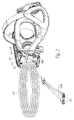
- FIG. 1 is an isometric view of a HMD in accordance with an embodiment of the present technology.
- FIG. 2 is a rear isometric view of a portion of the HMD of FIG. 1 with portions of the strap assembly and front display module not shown for clarity.
- FIGS. 3 and 4 are rear isometric and exploded rear isometric views of the cable retention assembly and portions of the front display module of FIG. 2 configured in accordance with an embodiment of the present technology.
- FIG. 5 is a rear isometric view of the receptacle of the cable retention assembly of FIGS. 3 and 4 .
- FIG. 6 is an enlarged rear isometric view of the retaining clip of the cable retention assembly of FIGS. 3 and 4 .
- FIG. 7 is an enlarged rear isometric view of the connector of the cable retention assembly of FIGS. 3 and 4 .
- a head mounted display (“HMD”) with a front display module having a cable retention assembly is disclosed.
- the cable retention assembly removably secures the cable in position and provides strain relief to the cable.
- the cable retention assembly includes a receptacle sized and shaped to receive a connector on one end of the cable and a clip portion for removably securing the connector therein.
- FIG. 1 is an isometric view of a HMD 100 in accordance with an embodiment of the present technology.
- the HMD 100 is configured for use with a virtual reality (VR) system 10 , such as the RiftTM available from OculusTM.
- the HMD 100 includes a front display module 101 and an adjustable strap assembly 103 operatively coupled to opposing lateral sides of the front display module 101 with joints 105 .
- the strap assembly 103 includes one or more head straps 102 and a pair of substantially rigid connector arms 107 (identified individually as a first connector arm 107 a and a second connector arm 107 b ) connected to the head straps 102 at opposing sides of the strap assembly 103 .
- the stiff connector arms 107 attach at the joints 105 to adjustably couple the strap assembly 103 to the sides of the front display module 101 so as to securely and comfortably retain the front display module 101 adjacent the front of the user's face and over the user's eyes.
- the front display module 101 has a housing 108 that contains optics 104 and one or more displays 106 operatively connected to a plurality of electronic components 120 that may be carried by one or more circuit boards 121 .
- the displays 106 and associated electronic components 120 are operatively coupleable to the VR system 10 via a power and/or data communication cable 123 .
- the housing 108 of the front display module 101 contains a cable retention assembly 125 positioned adjacent to a circuit board 121 that has a connector 124 releasably connectable to a mating connector 126 on a proximal end 129 a of the cable 123 to interconnect the cable 123 to the electronic components 120 .
- the distal end 129 b of the cable 123 in the illustrated embodiment has one or more connectors 127 that connect to corresponding receiving connectors 133 , such as ports or the like, on the VR system 10 .
- the connectors 126 and 127 on the cable 123 and the associated mating connectors 124 and 133 can include corresponding USB, USB-C, HDMI, and/or other suitable electronic interfaces for providing power and/or data between the front display module 101 and the VR system 10 via the cable 123 .
- FIG. 2 is an enlarged rear isometric view of a portion of the HMD 100 of FIG. 1 .
- the illustrated HMD 100 has a contoured facial interface 135 (e.g., a foam interface) connected to the rear portion of the front display module 101 and shaped to contact a user's face when wearing the HMD 100 .
- the circuit board 121 is supported on a top portion of the front display module's housing 108 forward of the facial interface 135 .
- the cable retention assembly 125 is positioned over at least a portion of the circuit board 121 that includes the connector 124 .
- the cable 123 enters the upper left portion of the front display module 101 just forward of contoured facial interface 135 , such that the cable's connector 126 operably mates with the circuit board's connector 124 .
- the cable's connector 126 is carried and releasably held by the cable retention assembly 125 in a substantially fixed position relative to the circuit board's mating connector 124 .
- substantially all tensile and/or torsional loads applied to the cable 123 are reacted by the cable retention assembly 125 rather than by the mating interface between the connectors 124 and 126 .
- This configuration substantially isolating the circuit board's connector 124 from axial or torsional loads applied to the cable 123 , which substantially relieves the connectors from tensile or torsional strain during use of the HMD 100 .
- FIGS. 3 and 4 are rear isometric and rear exploded isometric views, respectively, of portions of the circuit board 121 and cable retention assembly 125 of FIG. 2 .
- the cable retention assembly 125 includes a main frame or body portion 137 positioned in the front display module 101 and atop at least a portion of the circuit board 121 .
- the body portion 137 has a connector receptacle 139 positioned adjacent to the circuit board's connector 124 .
- the connector receptacle 139 is positioned on the left side of the body portion 137 generally between the circuit board's connector 124 and the facial interface 135 ( FIG. 2 ).
- the connector receptacle 139 is sized, shaped, and positioned so that, when the cable's connector 127 is plugged into or otherwise operably engaged with the circuit board's mating connector 124 , the cable's connector 127 is at least partially within and protected by the connector receptacle 139 .
- the cable retention assembly 125 has a retaining clip 141 that releasably locks the cable's connector 127 within and to the connector receptacle 139 when the cable is in an installed position.
- the components of the cable retention assembly 125 can be formed from an injection molding process (e.g., overmolding, insert molding, etc.) and/or made from a common material, such as plastic, composite, metal, or other suitable material. In other embodiments, the components of the cable retention assembly 125 can be made of different materials.
- FIG. 5 is an isometric view of the body portion 137 and the connector receptacle 139 of the cable retention assembly 125 of FIGS. 3 and 4 .
- the connector receptacle 139 of the illustrated embodiment includes opposing open ends 143 and 145 .
- the connector receptacle 139 is configured to slidably receive the cable's connector 127 ( FIG. 4 ) through the open distal end 143 until the connector's plug portion 131 a extends through the open proximal end 145 far enough to mate with the circuit board's connector 124 ( FIG. 4 ).
- the retaining clip 141 ( FIG. 4 ) is attached to connector receptacle 139 in a position to releasably engage and retain the cable's connector 129 within the connector receptacle 139 .
- the connector receptacle 139 has lateral sidewalls 146 with openings 147 (e.g., cut-outs, windows) generally adjacent to the open proximal end 145 .
- the receptacle 139 also has a plurality of retention and alignment pins 151 projecting away from a bottom wall 150 that extends between the lateral sidewalls 146 .
- FIG. 6 is an isometric view of the retaining clip 141 separated from the connector receptacle 139 FIG. 5 .
- the retaining clip 141 is attached to the receptacle 139 adjacent to the open proximal end 145 .
- the retaining clip 141 has a pair of spaced apart, flexible engagement tabs 149 that extend at least partially through the openings 147 in the receptacle's sidewalls 146 .
- the engagement tabs 149 are movable relative to the openings 147 between deflected and undeflected positions.
- the bottom of the retaining clip 141 also has a plurality of alignment apertures 153 that snugly receive the alignment pins 151 projecting from the bottom wall 150 of the receptacle 139 ( FIG. 5 ).
- the mating arrangement between the retaining clip's alignment apertures 153 and the connector receptacle's alignment pins 151 FIG.
- the retaining clip 141 of the illustrated embodiment is a separate component attached to the receptacle 139 , although the retaining clip 141 or portions of the retaining clip, such as the engagement tabs 149 , can be integrally connected to the receptacle for releasably engaging the cable's connector 127 .
- the engagement tabs 149 of the illustrated embodiment have generally wedge-shaped locking members 152 projecting inwardly toward each other, such that when the retaining clip 141 is on the connector receptacle 139 , the locking members 152 extend at least partially through the corresponding lateral side openings 147 when in the undeflected position.
- the engagement tabs 149 can be formed from metal, plastic or other elastically deformable or resilient material, such that the engagement tabs 149 are biased away from the deflected position toward the undeflected position.
- the retention features 157 can be deflected laterally outwardly relative to the receptacle's sidewalls 146 by contact with a leading shoulder portion 155 of the cable's connector 127 ( FIG. 4 ) as it passes through the receptacle 139 into the installed position engaging the circuit board's connector 124 .
- FIG. 7 is an isometric view of an embodiment of the cable's connector 127 of FIGS. 3 and 4 .
- the connector 127 has retention features 157 (e.g., recesses) on lateral sides of the connector 127 and positioned rearward of the leading should portion 155 .
- the retention features 157 are shaped and positioned to receive and retain the locking members 152 of the engagement tabs 149 of the retaining clip 141 when the connector 127 is in the installed position and the engagement tabs 149 return or “rebound” from the deflected position toward the initial undeflected position to secure the connector 127 a within the receptacle 139 and in connection with the circuit board 121 .
- the retention features 157 are corresponding wedge-shaped recesses on lateral sides of the connector 127 .
- the leading shoulder portion 155 presses laterally against the wedge-shaped locking members 152 and move the engagement tabs 149 to the deflected position.
- the engagement tabs 149 automatically return toward the undeflected position with the locking members 152 positioned at least partially in the corresponding wedge-shaped recessed retention features 157 .
- the connector 127 will remain locked in place within the receptacle 139 until the engagement tabs are manually moved to the deflected position wherein the locking members do not block the connector 127 from being slid axially out of the receptacle 139 .
- the connector receptacle 139 and the cable retention assembly 125 mounted atop the circuit board 121 ( FIG. 4 ) in the illustrated embodiment is configured to react any axial loads that may be applied to the cable 123 during use of the HMD 100 , such as if the cable is snagged or otherwise pulled relative to the front display mount.
- the receptacle 139 and the retaining clip 141 are also configured to snugly receive and engage the cable's connector 127 so as to react any torsional loads that may be applied to the connector 127 during use, such as due to gravitational forces, normal torsional loads experienced at the front display module during typical active use by the user, motion of the user's head, rotational positioning of the front display module by the user, etc.
- the cable retention assembly 125 thus, removably secures the cable 123 to the front display module 101 and provides strain relief for the cable 123 and the connectors at the front mounted display 101 .
Landscapes
- Engineering & Computer Science (AREA)
- Physics & Mathematics (AREA)
- Theoretical Computer Science (AREA)
- General Physics & Mathematics (AREA)
- General Engineering & Computer Science (AREA)
- Microelectronics & Electronic Packaging (AREA)
- Computer Hardware Design (AREA)
- Human Computer Interaction (AREA)
- Optics & Photonics (AREA)
- Details Of Connecting Devices For Male And Female Coupling (AREA)
Abstract
Description
Claims (18)
Priority Applications (1)
| Application Number | Priority Date | Filing Date | Title |
|---|---|---|---|
| US14/964,439 US9763342B2 (en) | 2015-12-09 | 2015-12-09 | Cable retention assembly for a head mounted display |
Applications Claiming Priority (1)
| Application Number | Priority Date | Filing Date | Title |
|---|---|---|---|
| US14/964,439 US9763342B2 (en) | 2015-12-09 | 2015-12-09 | Cable retention assembly for a head mounted display |
Publications (2)
| Publication Number | Publication Date |
|---|---|
| US20170171992A1 US20170171992A1 (en) | 2017-06-15 |
| US9763342B2 true US9763342B2 (en) | 2017-09-12 |
Family
ID=59021004
Family Applications (1)
| Application Number | Title | Priority Date | Filing Date |
|---|---|---|---|
| US14/964,439 Active 2035-12-17 US9763342B2 (en) | 2015-12-09 | 2015-12-09 | Cable retention assembly for a head mounted display |
Country Status (1)
| Country | Link |
|---|---|
| US (1) | US9763342B2 (en) |
Cited By (3)
| Publication number | Priority date | Publication date | Assignee | Title |
|---|---|---|---|---|
| US10289194B2 (en) | 2017-03-06 | 2019-05-14 | Universal City Studios Llc | Gameplay ride vehicle systems and methods |
| US11200656B2 (en) | 2019-01-11 | 2021-12-14 | Universal City Studios Llc | Drop detection systems and methods |
| US12554140B2 (en) | 2020-03-27 | 2026-02-17 | ResMed Pty Ltd | Positioning, stabilising, and interfacing structures and system incorporating same |
Families Citing this family (7)
| Publication number | Priority date | Publication date | Assignee | Title |
|---|---|---|---|---|
| CN106253371A (en) * | 2016-07-29 | 2016-12-21 | 北京小鸟看看科技有限公司 | One wears display electric power system |
| US10224670B2 (en) * | 2017-07-17 | 2019-03-05 | Facebook Technologies, Llc | Circuit board with anchor cleat for a connector |
| USD839816S1 (en) * | 2017-07-17 | 2019-02-05 | Brunswick Corporation | Dipstick |
| TWI626473B (en) * | 2017-07-25 | 2018-06-11 | 廣達電腦股份有限公司 | Head-mounted display |
| IT201800005868A1 (en) * | 2018-05-30 | 2019-11-30 | CABLE FOR CONNECTING A DEVICE THAT CAN BE MOUNTED ON THE HEAD WITH AN ELECTRONIC UNIT AND RELATED DEVICE. | |
| CN112433972A (en) * | 2019-08-26 | 2021-03-02 | 华为技术有限公司 | Adapter box and VR equipment |
| US20250361970A1 (en) * | 2024-05-23 | 2025-11-27 | Hyuntae Kim | Apparatus for reducing perceived weight of vr headset |
Citations (6)
| Publication number | Priority date | Publication date | Assignee | Title |
|---|---|---|---|---|
| US4376565A (en) * | 1981-02-17 | 1983-03-15 | Amp Incorporated | Electrical connector keying means |
| US4678121A (en) * | 1983-06-17 | 1987-07-07 | Amp Incorporated | Multiplane connector system |
| US20060160399A1 (en) * | 2004-12-17 | 2006-07-20 | Dawiedczyk Daniel L | Connector guide with latch and connectors therefor |
| US7794263B1 (en) * | 2009-09-30 | 2010-09-14 | Apple Inc. | Connector receptacle housings having reduced-wear finger contacts and reduced seam visibility |
| US8461465B2 (en) * | 2010-05-28 | 2013-06-11 | Apple Inc. | Conductive frame for an electrical connector |
| US20160260251A1 (en) * | 2015-03-06 | 2016-09-08 | Sony Computer Entertainment Inc. | Tracking System for Head Mounted Display |
-
2015
- 2015-12-09 US US14/964,439 patent/US9763342B2/en active Active
Patent Citations (6)
| Publication number | Priority date | Publication date | Assignee | Title |
|---|---|---|---|---|
| US4376565A (en) * | 1981-02-17 | 1983-03-15 | Amp Incorporated | Electrical connector keying means |
| US4678121A (en) * | 1983-06-17 | 1987-07-07 | Amp Incorporated | Multiplane connector system |
| US20060160399A1 (en) * | 2004-12-17 | 2006-07-20 | Dawiedczyk Daniel L | Connector guide with latch and connectors therefor |
| US7794263B1 (en) * | 2009-09-30 | 2010-09-14 | Apple Inc. | Connector receptacle housings having reduced-wear finger contacts and reduced seam visibility |
| US8461465B2 (en) * | 2010-05-28 | 2013-06-11 | Apple Inc. | Conductive frame for an electrical connector |
| US20160260251A1 (en) * | 2015-03-06 | 2016-09-08 | Sony Computer Entertainment Inc. | Tracking System for Head Mounted Display |
Cited By (8)
| Publication number | Priority date | Publication date | Assignee | Title |
|---|---|---|---|---|
| US10289194B2 (en) | 2017-03-06 | 2019-05-14 | Universal City Studios Llc | Gameplay ride vehicle systems and methods |
| US10528123B2 (en) | 2017-03-06 | 2020-01-07 | Universal City Studios Llc | Augmented ride system and method |
| US10572000B2 (en) | 2017-03-06 | 2020-02-25 | Universal City Studios Llc | Mixed reality viewer system and method |
| US12153723B2 (en) | 2017-03-06 | 2024-11-26 | Universal City Studios Llc | Systems and methods for layered virtual features in an amusement park environment |
| US11200656B2 (en) | 2019-01-11 | 2021-12-14 | Universal City Studios Llc | Drop detection systems and methods |
| US11200655B2 (en) | 2019-01-11 | 2021-12-14 | Universal City Studios Llc | Wearable visualization system and method |
| US11210772B2 (en) | 2019-01-11 | 2021-12-28 | Universal City Studios Llc | Wearable visualization device systems and methods |
| US12554140B2 (en) | 2020-03-27 | 2026-02-17 | ResMed Pty Ltd | Positioning, stabilising, and interfacing structures and system incorporating same |
Also Published As
| Publication number | Publication date |
|---|---|
| US20170171992A1 (en) | 2017-06-15 |
Similar Documents
| Publication | Publication Date | Title |
|---|---|---|
| US9763342B2 (en) | Cable retention assembly for a head mounted display | |
| US6137260A (en) | Multifunction connector for hand-held terminal docks | |
| US9246262B2 (en) | Electrical connector including latch assembly with pull tab | |
| US9857596B2 (en) | Strap assembly with flex circuit for a head mounted display | |
| EP1172672B1 (en) | Dual-function dust cover for fiber optic connector | |
| US7290941B2 (en) | Modular fiber optic connector system | |
| US5216732A (en) | Optical fiber guide connection | |
| CN106165207A (en) | connector assembly | |
| US9799984B2 (en) | Protective cap for a plug connector housing | |
| US6604861B2 (en) | Cable management system for fiber optic connector assemblies | |
| CN101494337A (en) | Connector assembly having a slider element | |
| US20190302374A1 (en) | Hybrid ingress protected connector and adapter assembly | |
| EP1172673A2 (en) | Alignment system for fiber optic connectors | |
| EP1732179A1 (en) | Repeatably releasable cable connector | |
| CN113841308B (en) | plug connector | |
| MY132200A (en) | Duplex connector | |
| US20070141918A1 (en) | Connector for electronic device | |
| EP2992371A2 (en) | Connector assemblies and methods for providing sealing and strain-relief | |
| CN104297861B (en) | A kind of optical fiber connector plug | |
| WO2014085116A1 (en) | Connector systems having receptacle assembly and plug assembly | |
| US9810867B2 (en) | Connector assembly | |
| US7892045B2 (en) | Connector having interlocking components | |
| CA2603263A1 (en) | Plug-in connection | |
| US6758688B2 (en) | Connector securing device | |
| WO2010047795A1 (en) | Connector including housing shells secured together |
Legal Events
| Date | Code | Title | Description |
|---|---|---|---|
| AS | Assignment |
Owner name: OCULUS VR, LLC, CALIFORNIA Free format text: ASSIGNMENT OF ASSIGNORS INTEREST;ASSIGNORS:LONG, CLARE REGIMBAL;BROWN, RYAN HAMILTON;DEVOE, MATTHEW JAMES;AND OTHERS;SIGNING DATES FROM 20160316 TO 20160331;REEL/FRAME:039677/0618 |
|
| STCF | Information on status: patent grant |
Free format text: PATENTED CASE |
|
| AS | Assignment |
Owner name: FACEBOOK TECHNOLOGIES, LLC, CALIFORNIA Free format text: CHANGE OF NAME;ASSIGNOR:OCULUS VR, LLC;REEL/FRAME:047112/0836 Effective date: 20180904 |
|
| MAFP | Maintenance fee payment |
Free format text: PAYMENT OF MAINTENANCE FEE, 4TH YEAR, LARGE ENTITY (ORIGINAL EVENT CODE: M1551); ENTITY STATUS OF PATENT OWNER: LARGE ENTITY Year of fee payment: 4 |
|
| AS | Assignment |
Owner name: META PLATFORMS TECHNOLOGIES, LLC, CALIFORNIA Free format text: CHANGE OF NAME;ASSIGNOR:FACEBOOK TECHNOLOGIES, LLC;REEL/FRAME:060199/0876 Effective date: 20220318 |
|
| MAFP | Maintenance fee payment |
Free format text: PAYMENT OF MAINTENANCE FEE, 8TH YEAR, LARGE ENTITY (ORIGINAL EVENT CODE: M1552); ENTITY STATUS OF PATENT OWNER: LARGE ENTITY Year of fee payment: 8 |