US9759591B2 - Undershot gate flow control system with flow diverter - Google Patents
Undershot gate flow control system with flow diverter Download PDFInfo
- Publication number
- US9759591B2 US9759591B2 US14/435,144 US201314435144A US9759591B2 US 9759591 B2 US9759591 B2 US 9759591B2 US 201314435144 A US201314435144 A US 201314435144A US 9759591 B2 US9759591 B2 US 9759591B2
- Authority
- US
- United States
- Prior art keywords
- gate
- acoustic
- pipe
- leaf
- gate leaf
- Prior art date
- Legal status (The legal status is an assumption and is not a legal conclusion. Google has not performed a legal analysis and makes no representation as to the accuracy of the status listed.)
- Active, expires
Links
Images


Classifications
-
- G—PHYSICS
- G01—MEASURING; TESTING
- G01F—MEASURING VOLUME, VOLUME FLOW, MASS FLOW OR LIQUID LEVEL; METERING BY VOLUME
- G01F1/00—Measuring the volume flow or mass flow of fluid or fluent solid material wherein the fluid passes through a meter in a continuous flow
- G01F1/66—Measuring the volume flow or mass flow of fluid or fluent solid material wherein the fluid passes through a meter in a continuous flow by measuring frequency, phase shift or propagation time of electromagnetic or other waves, e.g. using ultrasonic flowmeters
- G01F1/667—Arrangements of transducers for ultrasonic flowmeters; Circuits for operating ultrasonic flowmeters
-
- E—FIXED CONSTRUCTIONS
- E02—HYDRAULIC ENGINEERING; FOUNDATIONS; SOIL SHIFTING
- E02B—HYDRAULIC ENGINEERING
- E02B13/00—Irrigation ditches, i.e. gravity flow, open channel water distribution systems
- E02B13/02—Closures for irrigation conduits
-
- E—FIXED CONSTRUCTIONS
- E02—HYDRAULIC ENGINEERING; FOUNDATIONS; SOIL SHIFTING
- E02B—HYDRAULIC ENGINEERING
- E02B7/00—Barrages or weirs; Layout, construction, methods of, or devices for, making same
- E02B7/20—Movable barrages; Lock or dry-dock gates
- E02B7/26—Vertical-lift gates
-
- G—PHYSICS
- G01—MEASURING; TESTING
- G01B—MEASURING LENGTH, THICKNESS OR SIMILAR LINEAR DIMENSIONS; MEASURING ANGLES; MEASURING AREAS; MEASURING IRREGULARITIES OF SURFACES OR CONTOURS
- G01B13/00—Measuring arrangements characterised by the use of fluids
- G01B13/02—Measuring arrangements characterised by the use of fluids for measuring length, width or thickness
- G01B13/06—Measuring arrangements characterised by the use of fluids for measuring length, width or thickness for measuring thickness
- G01B13/065—Height gauges
-
- G—PHYSICS
- G01—MEASURING; TESTING
- G01F—MEASURING VOLUME, VOLUME FLOW, MASS FLOW OR LIQUID LEVEL; METERING BY VOLUME
- G01F1/00—Measuring the volume flow or mass flow of fluid or fluent solid material wherein the fluid passes through a meter in a continuous flow
- G01F1/002—Measuring the volume flow or mass flow of fluid or fluent solid material wherein the fluid passes through a meter in a continuous flow wherein the flow is in an open channel
-
- G—PHYSICS
- G01—MEASURING; TESTING
- G01F—MEASURING VOLUME, VOLUME FLOW, MASS FLOW OR LIQUID LEVEL; METERING BY VOLUME
- G01F1/00—Measuring the volume flow or mass flow of fluid or fluent solid material wherein the fluid passes through a meter in a continuous flow
- G01F1/66—Measuring the volume flow or mass flow of fluid or fluent solid material wherein the fluid passes through a meter in a continuous flow by measuring frequency, phase shift or propagation time of electromagnetic or other waves, e.g. using ultrasonic flowmeters
-
- G—PHYSICS
- G01—MEASURING; TESTING
- G01P—MEASURING LINEAR OR ANGULAR SPEED, ACCELERATION, DECELERATION, OR SHOCK; INDICATING PRESENCE, ABSENCE, OR DIRECTION, OF MOVEMENT
- G01P5/00—Measuring speed of fluids, e.g. of air stream; Measuring speed of bodies relative to fluids, e.g. of ship, of aircraft
- G01P5/24—Measuring speed of fluids, e.g. of air stream; Measuring speed of bodies relative to fluids, e.g. of ship, of aircraft by measuring the direct influence of the streaming fluid on the properties of a detecting acoustical wave
- G01P5/245—Measuring speed of fluids, e.g. of air stream; Measuring speed of bodies relative to fluids, e.g. of ship, of aircraft by measuring the direct influence of the streaming fluid on the properties of a detecting acoustical wave by measuring transit time of acoustical waves
-
- E—FIXED CONSTRUCTIONS
- E02—HYDRAULIC ENGINEERING; FOUNDATIONS; SOIL SHIFTING
- E02B—HYDRAULIC ENGINEERING
- E02B7/00—Barrages or weirs; Layout, construction, methods of, or devices for, making same
- E02B7/20—Movable barrages; Lock or dry-dock gates
- E02B7/26—Vertical-lift gates
- E02B7/28—Vertical-lift gates with sliding gates
-
- E—FIXED CONSTRUCTIONS
- E02—HYDRAULIC ENGINEERING; FOUNDATIONS; SOIL SHIFTING
- E02B—HYDRAULIC ENGINEERING
- E02B8/00—Details of barrages or weirs ; Energy dissipating devices carried by lock or dry-dock gates
- E02B8/04—Valves, slides, or the like; Arrangements therefor; Submerged sluice gates
Definitions
- the present invention provides an undershot gate system to control flow of liquid through an open channel or pipe, said system including a gate leaf adapted to be raised and lowered by a control means to allow flow of liquid along said open channel or pipe, said gate including a flow diverter at an end of said gate leaf to guide liquid under said gate leaf and through an opening when said gate leaf is in an open position.
- said flow diverter includes a substantially horizontally disposed projection from one side of said end of said gate leaf, either upstream or downstream of said gate leaf.
- a substantially horizontally disposed projection from one side of said end of said gate leaf, either upstream or downstream of said gate leaf.
- an arcuate section is provided along the free end of said substantially horizontally disposed projection.
- said flow diverter includes an arcuate section along one side of said end of said gate leaf.
- said flow diverter further includes a substantially horizontally disposed projection from the other side of said end of said gate leaf.
- said undershot gate system further includes a pair of acoustic transducers on the bottom of said open channel or pipe, adapted to provide an acoustic path to and from underneath said substantially horizontally disposed projection to allow measurement of the opening of said gate leaf.
- said undershot gate system further includes a plurality of pairs of acoustic transducers forming an acoustic array on opposing sides of said open channel or pipe to provide, in use, a plurality of multiple planes of crossed acoustic paths for measurement of flow velocity through said gate opening.
- said plurality of pairs of acoustic transducers on opposing sides of said open channel or pipe are downstream and adjacent said gate leaf.
- said plurality of pairs of acoustic transducers on opposing sides of said open channel or pipe are upstream and adjacent said gate leaf.
- one set of respective acoustic transducers of said plurality of pairs of acoustic transducers on opposing sides of said open channel or. pipe are downstream and adjacent said gate leaf, and the other set of respective acoustic transducers of said plurality of pairs of acoustic transducers on opposing sides of said open channel or pipe are upstream and adjacent said gate leaf, with said plurality of multiple planes of crossed acoustic paths crossing through said gate opening.
- the present invention provides an undershot gate system to control flow of liquid through an open channel or pipe, said system including a gate leaf adapted to be raised and lowered by a control means to allow flow of liquid along said open channel or pipe, a plurality of pairs of acoustic transducers forming an acoustic array on opposing sides of said open channel or pipe to provide, in use, a plurality of multiple planes of crossed acoustic paths for measurement of flow velocity through said gate opening, and a means to measure the height of the opening of said gate leaf.
- said undershot gate system further includes a pair of acoustic transducers on the bottom of said open channel or pipe, adapted to provide an acoustic path to and from underneath said gate leaf to allow measurement of the opening of said gate leaf.
- said plurality of pairs of acoustic transducers on opposing sides of said open channel or pipe are downstream and adjacent said gate leaf.
- one set of respective acoustic transducers of said plurality of pairs of acoustic transducers on opposing sides of said open channel or pipe are downstream and adjacent said gate leaf, and the other set of respective acoustic transducers of said plurality of pairs of acoustic transducers on opposing sides of said open channel or pipe are upstream and adjacent said gate leaf, with said plurality of multiple planes of crossed acoustic paths crossing through said gate opening.
- Preferably said plurality of pairs of acoustic transducers have a small beam angle to the direction of flow, to allow each acoustic array to have a shorter width.
- said undershot gate system further includes a flow diverter at an end of said gate leaf to guide liquid under said gate leaf, and through the gate opening, when said gate leaf is in an open position.
- said flow diverter includes an arcuate section along one side of said end of said gate leaf.
- said flow diverter further includes a substantially horizontally disposed projection from the other side of said end of said gate leaf.
- said flow diverter includes a substantially horizontally disposed projection from one side of said end of said gate leaf, either upstream or downstream of said gate leaf.
- a substantially horizontally disposed projection from one side of said end of said gate leaf, either upstream or downstream of said gate leaf.
- an arcuate section is provided along the free end of said substantially horizontally disposed projection.
- the present invention provides a method of measuring flow rate of a liquid passing through an open gate of an undershot gate system installed in an open channel or pipe, said method including the steps of: providing a plurality of pairs of acoustic transducers forming an acoustic array on opposing sides of said open channel or pipe, said acoustic arrays producing a plurality of multiple planes of crossed acoustic paths; providing means to measure the height of said open gate relative to a base of said open channel or pipe; determining a vertical velocity profile of said liquid passing through said open gate utilising said acoustic arrays; determining the height of said open gate utilising said means to measure the height of said open gate relative to said base of said open channel or pipe; calculating a velocity integral of said vertical velocity profile utilising said determined height of said open gate; and, calculating said flow rate of said liquid passing through said open gate by multiplying said velocity integral by a predetermined internal width of said acoustic arrays.
- FIG. 1 is a cross-sectional view of an undershot gate in an irrigation system, with the gate open and showing the flow of water through the gate;
- FIG. 2 is a similar view to that of FIG. 1 , with an array of acoustic transducers on the downstream side of an undershot gate installed in an open channel according to a first aspect of the invention;
- FIG. 3 is an enlarged view of FIG. 1 , showing the velocity profiles around the gate Shown in FIG. 1 ;
- FIG. 4 is a similar view to that of FIG. 2 , where the gate edge has a preferred arcuate section along the frontal face of the gate;
- FIG. 5 is a similar view to that of FIG. 2 , where the acoustic transducers are on either side of the gate;
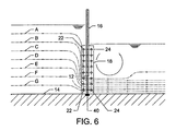
- FIG. 6 is a similar view to that of FIG. 5 , including a preferred device to measure the gate opening;
- FIG. 7 is a similar view to that of FIG. 4 , where the gate is in front of a head wall of a pipe;
- FIG. 8 is a perspective view of FIG. 2 ;
- FIG. 9 is a perspective view of FIG. 7 ;
- FIG. 10 is a cross-sectional view of an undershot gate having a preferred flow diverter and an array of acoustic transducers on the downstream side of the undershot gate installed in an open channel according to a second aspect of the invention
- FIG. 12 is a similar view to that of FIG. 11 , including a preferred device to measure the gate opening;
- FIG. 13 is a similar view to that of FIG. 10 , having an array of acoustic transducers on the upstream side of an undershot gate installed in an open channel, with a preferred arcuate section along the frontal face of the flow diverter;
- FIG. 14 is a similar view to that of FIG. 13 , including a preferred device to measure the gate opening;
- FIG. 15 is a similar view to that of FIG. 14 , where the gate is in front of a headwall of a pipe;
- FIG. 16 is similar view to that of FIG. 15 , with the gate and array of acoustic transducers mounted downstream of a pipe exit headwall.
- FIG. 17 is a view that depicts a motor controlling movement of an undershot gate in some embodiments.
- V is the velocity
- g is the gravitational acceleration
- V ⁇ square root over (2 g ( u ⁇ d )) ⁇
- the flow rate is determined by multiplying this velocity by the apparent area of the jetting velocity field passing through the orifice.
- This invention will allow the measurement of flow rate by measuring the jetting velocity field passing through a rectangular submerged orifice, and then multiplying this velocity field by the measured area of the rectangular submerged orifice.
- FIG. 1 there is shown a submerged rectangular orifice or opening 10 between the end face 12 —of a vertically movable gate 16 and the floor 14 of an irrigation open channel.
- the jetting velocities of the flow through gate 16 need to be measured to provide an accurate flow rate of water flowing through gate 16 .
- the streamlines A to G show a typical profile upstream, through and downstream of gate 16 . It can be seen that the streamlines A to G passing through the orifice 10 are parallel to the floor 14 of orifice 10 . If there is a sufficient straight approach length upstream of the orifice 10 then the streamlines A to G are also parallel to the walls (not shown) enclosing each side of the orifice 10 .
- FIG. 1 shows that there is generally known to be a contraction of the streamlines A to G downstream of the orifice 10 such that the depth of the velocity field hi is less than the opening height of the orifice x;
- the ratio h 1 /x is commonly referred to as a contraction coefficient (Cc).
- FIG. 1 shows that adjacent to the jetting streamlines A to G passing beneath the orifice 10 there is a stagnant region of water with a zero net velocity. The entire flow velocity passes through a depth h 1 .
- the flow rate passing through the orifice can be determined by integrating the vertical velocity profile passing through orifice 10 through a vertical range bounded by the floor 14 of the orifice 10 and by the height h 1 of the velocity field and then multiplying this velocity integral by the known width of the orifice 10 .
- the height of the velocity field h 1 may be determined through knowledge of the vertical velocity distribution as measured by an acoustic array.
- FIGS. 2 and 8 show the inclusion of a pair of opposing acoustic arrays 18 , 20 downstream of gate 16 .
- Each pair of acoustic arrays includes a pair of acoustic transducers 22 , 24 which operate in a crossed path arrangement i.e. acoustic transducer 22 of array 18 interacts with the opposing acoustic transducer 24 of array 20 to provide multiple planes of crossed path acoustic transit time velocity measurements.
- Each acoustic array 18 , 20 consist of eight (or any number as is reasonably practicable) horizontal velocity measurement planes. The velocity field passing through the rectangular submerged orifice 10 is measured based on the transit time velocity measurement principle as previously described in International Patent Application No.
- Acoustic arrays 18 , 20 have a small beam path angle relative to the direction of flow of 11.25°, however any angle may be used as is practicable. The choice of a small beam angle allows the acoustic arrays 18 , 20 to have a short overall assembly width such that the measured field of view lies immediately in the vicinity of the submerged rectangular orifice 10 .
- the acoustic arrays 18 , 20 are arranged adjacent gate 16 to ensure that there is a sufficient straight approach length upstream of orifice, such that each of the streamlines A to G pass through the length of the acoustic arrays 18 , 20 at a constant angle relative to the parallel walls 28 , 30 , enclosing each side of the orifice 10 , and do not experience a change in direction as they pass through the length of the acoustic arrays 18 , 20 .
- FIG. 2 illustrates that three velocity samples are available for computing the integral of the velocity field encompassed by the jetting flow streamlines.
- An abrupt transition is known to occur at the boundary of the jetting streamlines to a stationary water region behind the gate 16 with zero net velocity.
- the velocity field passing through the acoustic arrays 18 , 20 is vertically integrated from the floor 14 of the array to the ceiling of the array. It is known that the velocity field transitions abruptly from a high velocity to a zero velocity at the measured top boundary of the jetting velocity field.
- the location of the boundary of the velocity field can be determined by several means including by measurement of the gate opening height, and by analysis of the velocity profile observed by the acoustic planes located within the jetting velocity field. As the opening of the gate 16 changes, so does the boundary between the jetting flow and the stationary water along with the number of acoustic measurement planes incorporated into the velocity integration. Flow is computed by integrating this vertical velocity profile from the floor 14 of the acoustic arrays 18 , 20 to the ceiling of the acoustic arrays 18 , 20 , and multiplying this integral by the known internal width of the rectangular acoustic arrays 18 , 20 .
- the gate opening height is not used in the measurement of flow.
- the vertical velocity profile is integrated from the floor 14 of the acoustic arrays 18 , 20 , to the water level as measured by a water level sensor (not shown). This velocity integral is then multiplied by the known internal width of the rectangular acoustic arrays 18 , 20 to compute the flow rate passing through the acoustic arrays 18 , 20 .
- the orifice opening x may be measured by any suitable means including linear encoder, drawstring, or by an acoustic transducer (not shown) which measures the distance between the floor 14 of the orifice 10 and the end face 12 of gate 16 .
- Seals or a sealing compound 46 will prevent leakage between sidewalls 28 , 30 and acoustic arrays 18 , 20 .
- seals or a sealing compound 48 will prevent leakage between sidewalls 28 , 30 , and gate frame 50 in which gate 16 is slidably received.
- FIG. 3 illustrates the difference between the operations of the system disclosed in International Patent Application No. PCT/AU2010/001052, and the present embodiment.
- the invention defined in PCT/AU2010/001052 measures accurately upstream of a submerged orifice 10 where the vertical velocity distribution is a smooth function without any discontinuities.
- the present embodiment measures accurately downstream of the submerged orifice 10 where there is a ‘step function’ discontinuity in the vertical velocity distribution at the location of the gate end face 12 .
- the present embodiment uses the measured elevation of the gate 16 to locate the elevation of this velocity discontinuity, and hence, to determine the elevation at which the flow velocity transitions rapidly to zero.
- FIG. 3 shows the velocity profile upstream of the submerged orifice 10 on the left hand side velocity-elevation trend, and the velocity profile downstream of the submerged orifice 10 on the right hand side velocity-elevation trend.
- FIG. 3 illustrates that trapezoidal integration would result in a large over-estimate of flow passing beneath the gate.
- the over-read would be proportional to the triangular area 34 above the velocity discontinuity as shown in the right-hand side diagram.
- FIG. 4 is a similar embodiment to that of FIG. 2 , with an arcuate section 36 along the end of gate 16 upstream of gate 16 . It has been determined through computational fluid dynamics analysis, and through velocity field observations in a flow laboratory, that the inclusion of curved surface 38 on gate 16 reduces the contraction of the velocity field downstream of the orifice 10 , such that the height h 1 is closely approximated by the measurable orifice opening height x, i.e. h 1 is approximately equal to x. A comparison with FIG. 2 illustrates this difference.
- FIG. 5 is a further alternative embodiment to FIG. 2 , where gate 16 is located between the columns of acoustic transducers 22 , 24 of acoustic arrays 18 , 20 .
- gate 16 is located between the columns of acoustic transducers 22 , 24 of acoustic arrays 18 , 20 .
- Such an arrangement allows the acoustic transducers 22 , 24 to be very close to gate 16 .
- FIG. 6 is a variation of the embodiment of FIG. 5 , including an acoustic transducer 40 located on floor 14 that is used to determine the height from floor 14 to the end face or underside 12 of gate 16 .
- a standard acoustic distance measurement is undertaken in which an acoustic pulse is transmitted from the transducer 40 , reflects off the underside 12 of gate 16 , and returns to the transducer 40 or to a secondary receiving transducer (not shown).
- the flight time of an acoustic pulse is measured by timing electronics (not shown).
- Timing electronics not shown
- Two transducers are preferably used with one transducer acting as a transmitter and the other acting as a receiver. This configuration overcomes the blanking distance commonly associated with single transducer configurations, limiting the minimum distance that can be measured. Any embodiment of this specification can utilise transducer 40 , and therefore its use is not limited to
- FIG. 7 is a variation of the embodiment of FIG. 4 , where gate 16 in the open channel closes a pipe 42 with a headwall 44 .
- FIG. 7 has acoustic arrays 18 , 20 located downstream of gate 16 , and inserted into pipe 42 downstream of headwall 44 .
- FIG. 9 is a perspective view of a variation of the embodiment of FIG. 7 , with the addition of transducer 40 from FIG. 6 .
- This embodiment uses circular acoustic arrays 52 , 54 , instead of rectangular acoustic arrays 18 , 20 of the prior embodiments.
- FIG. 10 shows the same configuration as the embodiment of FIG. 2 , but with the inclusion of a flow diverter 56 rigidly connected to the downstream end of gate 16 that forms a ceiling 58 of closed rectangular acoustic arrays 18 , 20 , completely containing the jetting velocity profile.
- the flow passing through orifice 10 is computed by integrating the sampled velocity field from the floor 14 to the ceiling 58 of the acoustic arrays 18 , 20 .
- the height of the ceiling 58 of the acoustic arrays 18 , 20 is determined by any commonly employed linear measurement technique, with a preferred solution being an acoustic sensor, which is used to measure the height of the ceiling 58 above the floor 14 of the acoustic arrays 18 , 20 .
- the flow diverter 56 will assist in parallel alignment of flow streamlines relative to the floor 14 and flow diverter ceiling 58 . This will assist in more accurate measurement of flow velocities.
- FIG. 11 is a variation of the embodiment of FIG. 10 , with an arcuate section 60 along the end of gate 16 , upstream of gate 16 . It has been determined through computational fluid dynamics analysis, and through velocity field observations in a flow laboratory, that the inclusion of curved surface 62 reduces the contraction of the velocity field downstream of the orifice 10 , in a similar manner to the embodiment of FIG. 4 .
- FIG. 12 is a variation of the embodiment of FIG. 11 , including an acoustic transducers) 40 located on floor 14 that is used to determine the height from floor 14 to the ceiling 58 of flow diverter 56 , as described with reference to FIG. 6 .
- the configuration of the upward ranging transducer(s) 40 defined in this embodiment of the invention avoids any impact from silt on floor 14 .
- the ceiling 58 covers the upwardly ranging transducer(s) 40 such that no silt can settle upon them. Instead, the silt will settle on top of flow diverter 56 .
- jetting velocities passing through the meter will flush any debris or sediment off the face of the upward shooting acoustic transducers 40 .
- FIG. 13 is a variation of the embodiment shown in FIG. 11 , where the arcuate section 60 is affixed at the free end 64 of flow diverter 56 facing the upstream end of gate 16 , rather than the downstream end shown in FIG. 11 .
- acoustic arrays 18 , 20 are also positioned at the upstream end of gate 16 to create an adjustable geometry rectangular conduit which encompasses the acoustic arrays 18 , 20 , and which causes the streamlines passing through the acoustic arrays 18 , 20 to be parallel with the four walls of the rectangular conduit.
- This embodiment is well suited to installations where the acoustic arrays 18 , 20 cannot be located on the downstream side of gate 16 .
- FIG. 14 is a similar embodiment to that of FIG. 13 , which includes acoustic transducer(s) 40 to determine the height of ceiling 58 , of flow diverter 56 , as previously discussed with reference to FIG. 6 .
- FIG. 15 is a similar embodiment to that of FIG. 14 , where the acoustic arrays 18 , 20 are located upstream of the gate 16 , on a pipe entry headwall 44 of pipe 42 .
- FIG. 16 is a similar embodiment to that of FIG. 15 , only the direction of flow of water through the pipe 42 is reversed. Hence, this time the acoustic arrays 18 , 20 are located downstream of gate 16 , on the downstream exit headwall 44 of pipe 42 .
- FIG. 17 is a view that depicts a motor 66 controlling movement of an undershot gate 16 in some embodiments.
- movement of gate 16 is controlled by a motor 66 driven or hydraulic arm coupled to the top 68 of gate 16 .
- a motor 66 driven or hydraulic arm coupled to the top 68 of gate 16 .
Landscapes
- Engineering & Computer Science (AREA)
- Physics & Mathematics (AREA)
- General Physics & Mathematics (AREA)
- General Engineering & Computer Science (AREA)
- Structural Engineering (AREA)
- Fluid Mechanics (AREA)
- Mechanical Engineering (AREA)
- Civil Engineering (AREA)
- Electromagnetism (AREA)
- Aviation & Aerospace Engineering (AREA)
- Multimedia (AREA)
- Acoustics & Sound (AREA)
- Measuring Volume Flow (AREA)
- Investigating Or Analyzing Materials By The Use Of Ultrasonic Waves (AREA)
- Sliding Valves (AREA)
Applications Claiming Priority (3)
| Application Number | Priority Date | Filing Date | Title |
|---|---|---|---|
| AU2012904449 | 2012-10-11 | ||
| AU2012904449A AU2012904449A0 (en) | 2012-10-11 | Flow Measurement | |
| PCT/AU2013/001185 WO2014056046A1 (en) | 2012-10-11 | 2013-10-11 | Flow measurement |
Publications (2)
| Publication Number | Publication Date |
|---|---|
| US20160282159A1 US20160282159A1 (en) | 2016-09-29 |
| US9759591B2 true US9759591B2 (en) | 2017-09-12 |
Family
ID=50476792
Family Applications (1)
| Application Number | Title | Priority Date | Filing Date |
|---|---|---|---|
| US14/435,144 Active 2034-01-01 US9759591B2 (en) | 2012-10-11 | 2013-10-11 | Undershot gate flow control system with flow diverter |
Country Status (6)
| Country | Link |
|---|---|
| US (1) | US9759591B2 (de) |
| EP (1) | EP2906913B1 (de) |
| CN (1) | CN105051503B (de) |
| AU (1) | AU2013330229B2 (de) |
| IN (1) | IN2015DN03971A (de) |
| WO (1) | WO2014056046A1 (de) |
Cited By (2)
| Publication number | Priority date | Publication date | Assignee | Title |
|---|---|---|---|---|
| US20220042836A1 (en) * | 2020-08-07 | 2022-02-10 | Woodward, Inc. | Ultrasonic Flow Meter Flow Control |
| US11835374B2 (en) | 2021-03-17 | 2023-12-05 | Woodward, Inc. | Ultrasonic mass fuel flow meter |
Families Citing this family (5)
| Publication number | Priority date | Publication date | Assignee | Title |
|---|---|---|---|---|
| CN108775936B (zh) * | 2018-03-23 | 2020-04-10 | 中国航天系统科学与工程研究院 | 一种流量计量装置、计量方法及测控一体化闸门系统 |
| CN108824376B (zh) * | 2018-05-31 | 2019-12-17 | 中国地质大学(武汉) | 一种复式矩形流量堰的施工方法 |
| CN108589664A (zh) * | 2018-07-19 | 2018-09-28 | 唐山现代工控技术有限公司 | 一种可调堰闸的优化配置结构及方法 |
| CN114396023A (zh) * | 2022-01-20 | 2022-04-26 | 唐山现代工控技术有限公司 | 一种断面阵列扫描测流闸门及方法 |
| CN114814990B (zh) * | 2022-05-06 | 2023-08-11 | 自然资源部第一海洋研究所 | 一种海湾纳潮量预报与监测装置及其工作方法 |
Citations (7)
| Publication number | Priority date | Publication date | Assignee | Title |
|---|---|---|---|---|
| US3942328A (en) | 1975-02-24 | 1976-03-09 | Bunger Mills E | Automatic canal gate |
| US5780747A (en) * | 1995-12-18 | 1998-07-14 | Changmin Co., Ltd. | Open channel multichannel ultrasonic flowrate measurement apparatus and method |
| US20020066484A1 (en) * | 2000-12-06 | 2002-06-06 | Stringam Blair Lewis | Automated farm turnout |
| US6550345B1 (en) * | 2000-09-11 | 2003-04-22 | Daniel Industries, Inc. | Technique for measurement of gas and liquid flow velocities, and liquid holdup in a pipe with stratified flow |
| US20060005611A1 (en) * | 2002-05-31 | 2006-01-12 | Systec Controls Mess Und Regeltechnik Gmbh | Ultrasonic measurement of the running time and quantity for detecting the concentration of particles in a flowing fluid |
| US20100097892A1 (en) | 2006-11-28 | 2010-04-22 | Rubicon Research Pty Ltd. | Ultrasonic Level Detection Device With Flared Section for Reduced Distortion |
| US20120144930A1 (en) | 2009-08-18 | 2012-06-14 | David John Aughton | Flow meter assembly, gate assemblies and methods of flow measurement |
Family Cites Families (5)
| Publication number | Priority date | Publication date | Assignee | Title |
|---|---|---|---|---|
| FR2412060A1 (fr) * | 1977-12-14 | 1979-07-13 | Flonic Sa | Dispositif de mesure de debit pour canaux ouverts |
| JP3293193B2 (ja) * | 1992-10-09 | 2002-06-17 | 富士通株式会社 | 堰の放流量演算方法 |
| EP1582631B1 (de) * | 2004-04-02 | 2007-01-31 | KWT Holding B.V. | Vorrichtung um die Strömung eines Durchflussmediums zu sperren oder zu regeln |
| WO2010088731A1 (en) * | 2009-02-05 | 2010-08-12 | Rubicon Research Pty Ltd | Undershot sluice gate |
| CN201678988U (zh) * | 2010-05-12 | 2010-12-22 | 武汉大学 | 一种堰顶高程可变式量水堰 |
-
2013
- 2013-10-11 IN IN3971DEN2015 patent/IN2015DN03971A/en unknown
- 2013-10-11 AU AU2013330229A patent/AU2013330229B2/en active Active
- 2013-10-11 EP EP13845119.0A patent/EP2906913B1/de active Active
- 2013-10-11 US US14/435,144 patent/US9759591B2/en active Active
- 2013-10-11 CN CN201380064050.XA patent/CN105051503B/zh active Active
- 2013-10-11 WO PCT/AU2013/001185 patent/WO2014056046A1/en active Application Filing
Patent Citations (8)
| Publication number | Priority date | Publication date | Assignee | Title |
|---|---|---|---|---|
| US3942328A (en) | 1975-02-24 | 1976-03-09 | Bunger Mills E | Automatic canal gate |
| US5780747A (en) * | 1995-12-18 | 1998-07-14 | Changmin Co., Ltd. | Open channel multichannel ultrasonic flowrate measurement apparatus and method |
| US6550345B1 (en) * | 2000-09-11 | 2003-04-22 | Daniel Industries, Inc. | Technique for measurement of gas and liquid flow velocities, and liquid holdup in a pipe with stratified flow |
| US20020066484A1 (en) * | 2000-12-06 | 2002-06-06 | Stringam Blair Lewis | Automated farm turnout |
| US6427718B1 (en) * | 2000-12-06 | 2002-08-06 | The United States Of America As Represented By The Secretary Of The Interior | Automated farm turnout |
| US20060005611A1 (en) * | 2002-05-31 | 2006-01-12 | Systec Controls Mess Und Regeltechnik Gmbh | Ultrasonic measurement of the running time and quantity for detecting the concentration of particles in a flowing fluid |
| US20100097892A1 (en) | 2006-11-28 | 2010-04-22 | Rubicon Research Pty Ltd. | Ultrasonic Level Detection Device With Flared Section for Reduced Distortion |
| US20120144930A1 (en) | 2009-08-18 | 2012-06-14 | David John Aughton | Flow meter assembly, gate assemblies and methods of flow measurement |
Non-Patent Citations (1)
| Title |
|---|
| International Application No. PCT/AU2013/001185, Written Opinion and International Search Report mailed Dec. 17, 2013. |
Cited By (3)
| Publication number | Priority date | Publication date | Assignee | Title |
|---|---|---|---|---|
| US20220042836A1 (en) * | 2020-08-07 | 2022-02-10 | Woodward, Inc. | Ultrasonic Flow Meter Flow Control |
| US11885655B2 (en) | 2020-08-07 | 2024-01-30 | Woodward, Inc. | Ultrasonic flow meter having flow conditioning arrangements for flow controlling in a linear fluid conduit |
| US11835374B2 (en) | 2021-03-17 | 2023-12-05 | Woodward, Inc. | Ultrasonic mass fuel flow meter |
Also Published As
| Publication number | Publication date |
|---|---|
| CN105051503A (zh) | 2015-11-11 |
| AU2013330229A1 (en) | 2015-05-28 |
| EP2906913B1 (de) | 2022-07-06 |
| US20160282159A1 (en) | 2016-09-29 |
| EP2906913A4 (de) | 2016-06-22 |
| AU2013330229B2 (en) | 2017-03-02 |
| EP2906913A1 (de) | 2015-08-19 |
| CN105051503B (zh) | 2018-11-16 |
| IN2015DN03971A (de) | 2015-10-02 |
| WO2014056046A1 (en) | 2014-04-17 |
Similar Documents
| Publication | Publication Date | Title |
|---|---|---|
| US9759591B2 (en) | Undershot gate flow control system with flow diverter | |
| CA2771310C (en) | Flow meter assembly, gate assemblies and methods of flow measurement | |
| US10724886B2 (en) | Stratified flow multiphase flowmeter | |
| Pujara et al. | The swash of solitary waves on a plane beach: flow evolution, bed shear stress and run-up | |
| US7267013B2 (en) | System and method of measuring fluid flow | |
| Rolland et al. | A two-component acoustic velocity profiler for use in turbulent open-channel flow | |
| WO2009037501A1 (en) | Measurement of flow in a channel | |
| JP5297864B2 (ja) | 超音波式ガスメータ | |
| AU2017203457B2 (en) | Flow meter assembly | |
| Waluś | Mathematical modelling of an ultrasonic flowmeter primary device | |
| CN104487754A (zh) | 流体网中的泥沙控制 | |
| CN218211469U (zh) | 一种隧道涌水监测装置 | |
| Nóbrega et al. | Relation between free surface profiles and pressure profiles with respective fluctuations in hydraulic jumps | |
| JP5201726B2 (ja) | 液体の平均密度測定装置 | |
| Zhang et al. | Flowrate and Velocity Measurement in Nakdong River Using ADCP | |
| Callewaert | Study of the influence of bed roughness on the flow | |
| Hamill | Flow measurement | |
| JP5876118B2 (ja) | ガスメータ | |
| JP5632298B2 (ja) | ガスメータ | |
| El-Ansary et al. | Calibration of three common flow measurement devices for open channels | |
| CN115326356A (zh) | 一种地铁隧道洪涝模拟装置及地铁隧道洪涝模拟测试方法 | |
| Liem et al. | Mobile flood protection walls: experiments and reflections on the risk of flood waves caused by a failure | |
| JP2519437Y2 (ja) | 下水用管渠流量計 | |
| Aram et al. | Three-Dimensional Modeling of Density Current in Confined and Unconfined Channels | |
| Herschy | Rectangular thin-plate weir |
Legal Events
| Date | Code | Title | Description |
|---|---|---|---|
| AS | Assignment |
Owner name: RUBICON RESEARCH PTY LTD, AUSTRALIA Free format text: ASSIGNMENT OF ASSIGNORS INTEREST;ASSIGNORS:PEARSON, DAMIEN VERNON;TYRRELL, REECE JOSEPH;REEL/FRAME:036071/0677 Effective date: 20150527 |
|
| STCF | Information on status: patent grant |
Free format text: PATENTED CASE |
|
| CC | Certificate of correction | ||
| MAFP | Maintenance fee payment |
Free format text: PAYMENT OF MAINTENANCE FEE, 4TH YR, SMALL ENTITY (ORIGINAL EVENT CODE: M2551); ENTITY STATUS OF PATENT OWNER: SMALL ENTITY Year of fee payment: 4 |