US9757733B1 - Herb grinding device - Google Patents
Herb grinding device Download PDFInfo
- Publication number
- US9757733B1 US9757733B1 US14/838,188 US201514838188A US9757733B1 US 9757733 B1 US9757733 B1 US 9757733B1 US 201514838188 A US201514838188 A US 201514838188A US 9757733 B1 US9757733 B1 US 9757733B1
- Authority
- US
- United States
- Prior art keywords
- cylindrical section
- teeth
- section
- concentric
- rings
- Prior art date
- Legal status (The legal status is an assumption and is not a legal conclusion. Google has not performed a legal analysis and makes no representation as to the accuracy of the status listed.)
- Active - Reinstated, expires
Links
Images


Classifications
-
- B—PERFORMING OPERATIONS; TRANSPORTING
- B02—CRUSHING, PULVERISING, OR DISINTEGRATING; PREPARATORY TREATMENT OF GRAIN FOR MILLING
- B02C—CRUSHING, PULVERISING, OR DISINTEGRATING IN GENERAL; MILLING GRAIN
- B02C18/00—Disintegrating by knives or other cutting or tearing members which chop material into fragments
- B02C18/06—Disintegrating by knives or other cutting or tearing members which chop material into fragments with rotating knives
- B02C18/08—Disintegrating by knives or other cutting or tearing members which chop material into fragments with rotating knives within vertical containers
-
- A—HUMAN NECESSITIES
- A47—FURNITURE; DOMESTIC ARTICLES OR APPLIANCES; COFFEE MILLS; SPICE MILLS; SUCTION CLEANERS IN GENERAL
- A47J—KITCHEN EQUIPMENT; COFFEE MILLS; SPICE MILLS; APPARATUS FOR MAKING BEVERAGES
- A47J42/00—Coffee mills; Spice mills
- A47J42/22—Coffee mills; Spice mills having pulverising beaters or rotary knives
- A47J42/24—Coffee mills; Spice mills having pulverising beaters or rotary knives hand driven
-
- A—HUMAN NECESSITIES
- A47—FURNITURE; DOMESTIC ARTICLES OR APPLIANCES; COFFEE MILLS; SPICE MILLS; SUCTION CLEANERS IN GENERAL
- A47J—KITCHEN EQUIPMENT; COFFEE MILLS; SPICE MILLS; APPARATUS FOR MAKING BEVERAGES
- A47J42/00—Coffee mills; Spice mills
- A47J42/22—Coffee mills; Spice mills having pulverising beaters or rotary knives
- A47J42/30—Coffee mills; Spice mills having pulverising beaters or rotary knives having perforated container for the ground material; having sieves
-
- A—HUMAN NECESSITIES
- A47—FURNITURE; DOMESTIC ARTICLES OR APPLIANCES; COFFEE MILLS; SPICE MILLS; SUCTION CLEANERS IN GENERAL
- A47J—KITCHEN EQUIPMENT; COFFEE MILLS; SPICE MILLS; APPARATUS FOR MAKING BEVERAGES
- A47J42/00—Coffee mills; Spice mills
- A47J42/38—Parts or details
- A47J42/40—Parts or details relating to discharge, receiving container or the like; Bag clamps, e.g. with means for actuating electric switches
-
- B—PERFORMING OPERATIONS; TRANSPORTING
- B02—CRUSHING, PULVERISING, OR DISINTEGRATING; PREPARATORY TREATMENT OF GRAIN FOR MILLING
- B02C—CRUSHING, PULVERISING, OR DISINTEGRATING IN GENERAL; MILLING GRAIN
- B02C18/00—Disintegrating by knives or other cutting or tearing members which chop material into fragments
- B02C18/06—Disintegrating by knives or other cutting or tearing members which chop material into fragments with rotating knives
- B02C18/16—Details
- B02C18/18—Knives; Mountings thereof
-
- B—PERFORMING OPERATIONS; TRANSPORTING
- B02—CRUSHING, PULVERISING, OR DISINTEGRATING; PREPARATORY TREATMENT OF GRAIN FOR MILLING
- B02C—CRUSHING, PULVERISING, OR DISINTEGRATING IN GENERAL; MILLING GRAIN
- B02C18/00—Disintegrating by knives or other cutting or tearing members which chop material into fragments
- B02C18/06—Disintegrating by knives or other cutting or tearing members which chop material into fragments with rotating knives
- B02C18/16—Details
- B02C18/22—Feed or discharge means
- B02C18/2216—Discharge means
-
- B—PERFORMING OPERATIONS; TRANSPORTING
- B02—CRUSHING, PULVERISING, OR DISINTEGRATING; PREPARATORY TREATMENT OF GRAIN FOR MILLING
- B02C—CRUSHING, PULVERISING, OR DISINTEGRATING IN GENERAL; MILLING GRAIN
- B02C23/00—Auxiliary methods or auxiliary devices or accessories specially adapted for crushing or disintegrating not provided for in preceding groups or not specially adapted to apparatus covered by a single preceding group
- B02C23/08—Separating or sorting of material, associated with crushing or disintegrating
- B02C23/10—Separating or sorting of material, associated with crushing or disintegrating with separator arranged in discharge path of crushing or disintegrating zone
-
- B—PERFORMING OPERATIONS; TRANSPORTING
- B02—CRUSHING, PULVERISING, OR DISINTEGRATING; PREPARATORY TREATMENT OF GRAIN FOR MILLING
- B02C—CRUSHING, PULVERISING, OR DISINTEGRATING IN GENERAL; MILLING GRAIN
- B02C18/00—Disintegrating by knives or other cutting or tearing members which chop material into fragments
- B02C18/06—Disintegrating by knives or other cutting or tearing members which chop material into fragments with rotating knives
- B02C18/16—Details
- B02C2018/162—Shape or inner surface of shredder-housings
Definitions
- Grinders are commonly used for rendering foods and spices to mulch or particulate form.
- Conventional food grinders are typically a large home or industrial scale device suitable for shearing/grinding large volumes of food or herbs.
- Such food grinders may typically be driven by a motor that cause an excessive amount of heat energy to be transferred to the herb, thus increasing the risk of heating and spoiling the herb.
- certain herbs are required in only small quantities at a time for specific consumption.
- an herb grinding device comprises a first cylindrical section, a second cylindrical section, and at least a third cylindrical section.
- the first cylindrical section comprises a first cavity, a top surface, and a plurality of teeth extending from the top surface within the first cavity in at least two concentric teeth rings, each of the plurality of teeth comprising a V-shaped protrusion on a bottom end opposite the top surface and each of the at least two concentric teeth rings comprising at least two teeth.
- the second cylindrical section is rotatably coupled to the first cylindrical section and comprises a second cavity facing the first cavity, a second cylindrical section floor, a plurality of holes in the second cylindrical section floor, and a plurality of teeth extending from the second cylindrical section floor within the second cavity in at least two concentric teeth rings each comprising at least two teeth, each of the plurality of teeth comprising a V-shaped protrusion on a top end of the circular arced tooth opposite the second cylindrical section floor.
- the at least two concentric teeth rings of the second cylindrical section are positioned between the at least two concentric teeth rings of the first cylindrical section and the plurality of teeth of the second cylindrical section at least partially overlap the plurality of teeth of the first cylindrical section.
- the at least a third cylindrical section is removably coupled to the second cylindrical section and comprises a collection cavity.
- the second cylindrical section may comprise an annular flange positioned within the first cavity and interfacing an outer wall of the first cylindrical section.
- the at least third cylindrical section may comprise: a third cylindrical section removably coupled to the second cylindrical section opposite the first cylindrical section, the third cylindrical section comprising a channel extending through the third cylindrical section and one or more support arms extending across the channel; and, a fourth cylindrical section removably coupled to the third cylindrical section opposite the second cylindrical section, the fourth cylindrical section comprising the collection cavity.
- the plurality of holes in the second cylindrical section floor may be arranged in at least two concentric hole rings each comprising a plurality of holes, each of the at least two concentric hole rings being aligned with each of the at least two concentric teeth rings of the first cylindrical section.
- the plurality of holes may be substantially isosceles trapezoidal in shape with rounded corners, each of the plurality of holes being positioned such that a shortest side of the hole is proximate a center of the second cylindrical section floor and a longest side of the hole is distal the center of the second cylindrical section floor.
- Each of the plurality of teeth of the first cylindrical section and the second cylindrical section may be substantially planar, equal in dimension, and comprise a V-shaped protrusion on a first end of the tooth and a V-shaped protrusion on a second end of the tooth.
- the first section may comprise at least three concentric teeth rings each comprising at least four teeth of the plurality of teeth of the first section offset from at least four teeth of an adjacent concentric teeth ring of the plurality of concentric teeth rings of the first section.
- the second cylindrical section may comprise at least three concentric teeth rings each comprising at least four teeth of the plurality of teeth of the second cylindrical section offset from a plurality of teeth of an adjacent concentric teeth ring of the plurality of concentric teeth rings of the second cylindrical section.
- the first cylindrical section may be coupled to the second cylindrical section with a first magnet positioned at a center of the top surface and a second magnet positioned at a center of the second cylindrical section floor and in contact with the first magnet at a center point between the top surface and the second cylindrical section floor, and the herb grinding device may comprise a radiused edge within the collection cavity and a screen coupled to the one or more support arms and positioned within the channel.
- the first cylindrical section may comprise a recessed outer cavity, a T-shaped slot, and one or more bumper rings removably coupled the first section.
- the fourth cylindrical section may comprise a male lock notch positioned on an annular flange
- the third cylindrical section may comprise a female lock notch positioned within the third cylindrical section and configured to engage the male lock notch of the fourth cylindrical section
- the third cylindrical section may comprise a male lock notch positioned on an annular flange
- the second cylindrical section may comprise a female lock notch positioned within the second cylindrical section and configured to engaged the male lock notch of the third cylindrical section.
- Each of the first, second, third, and fourth cylindrical sections may each comprise a plurality of grips, each grip of the plurality of grips comprising alternating grip protrusions and grip recesses positioned axially along an outer perimeter of the respective section.
- the plurality of grips of the second, third, and fourth cylindrical sections align with one another when the male lock notch of the third cylindrical section is engaged with the female lock notch of the second cylindrical section and the male lock notch of the fourth cylindrical section is engaged with the female lock notch of the third cylindrical section.
- the one or more bumper rings may be positioned within the grip recesses of the plurality of grips of the first cylindrical section.
- an herb grinding device comprises a first cylindrical section, a second cylindrical section, a third cylindrical section, and a fourth cylindrical section.
- the first cylindrical section comprises a first cavity, a top surface, a plurality of teeth extending from the top surface within the first cavity.
- the second cylindrical section is rotatably and removably coupled to the first cylindrical section and comprises a second cavity facing the first cavity, a second cylindrical section floor, a plurality of holes in the second cylindrical section floor, a plurality of teeth extending from the second cylindrical section floor within the second cavity, and an annular flange positioned within the first cavity and interfacing an outer wall of the first cylindrical section.
- the third cylindrical section is removably coupled to the second cylindrical section opposite the first cylindrical section, the third cylindrical section comprising a channel extending through the third cylindrical section and one or more support arms extending across the channel.
- the fourth cylindrical section is removably coupled to the third cylindrical section opposite the second cylindrical section and comprises the collection cavity.
- Each of the first, second, third, and fourth cylindrical sections comprise a plurality of grips, each grip of the plurality of grips comprising alternating grip protrusions and grip recesses positioned axially along an outer perimeter of the respective section.
- the plurality of grips of the second, third, and fourth cylindrical sections align with one another when the third cylindrical section is coupled to the second cylindrical section and the fourth cylindrical section is coupled to the third cylindrical section.
- the plurality of teeth of the first cylindrical section may be positioned in at least two concentric teeth rings, each of the plurality of teeth of the first cylindrical section comprising a V-shaped protrusion on a bottom end opposite the top surface and each of the at least two concentric teeth rings comprising at least two teeth.
- the plurality of teeth of the second cylindrical section are positioned in at least two concentric teeth rings, each of the plurality of teeth of the second cylindrical section comprising a V-shaped protrusion on a bottom end opposite the top surface and each of the at least two concentric teeth rings comprising at least two teeth.
- the plurality of holes in the second cylindrical section floor may be arranged in at least two concentric hole rings each comprising a plurality of holes, each of the at least two concentric hole rings being aligned with each of the at least two concentric teeth rings of the first cylindrical section.
- the plurality of holes may be substantially isosceles trapezoidal in shape with rounded corners, each of the plurality of holes being positioned such that a shortest side of the hole is proximate a center of the second cylindrical section floor and a longest side of the hole is distal the center of the second cylindrical section floor.
- Each of the plurality of teeth of the first cylindrical section and the second cylindrical section may be substantially planar, equal in dimension and comprise a V-shaped protrusion on a first end of the tooth and a V-shaped protrusion on a second end of the tooth.
- the first cylindrical section may comprise at least three concentric teeth rings each comprising at least four teeth of the plurality of teeth of the first cylindrical section offset from at least four teeth of an adjacent concentric teeth ring of the plurality of concentric teeth rings of the first cylindrical section.
- the second cylindrical section comprises at least three concentric teeth rings each comprising at least four teeth of the plurality of teeth of the second cylindrical section offset from a plurality of teeth of an adjacent concentric teeth ring of the plurality of concentric teeth rings of the second cylindrical section.
- the first cylindrical section may be coupled to the second cylindrical section with a first magnet positioned at a center of the top surface and a second magnet positioned at a center of the second cylindrical section floor and in contact with the first magnet at a center point between the top surface and the second cylindrical section floor.
- the herb grinding device may comprise a radiused edge within the collection cavity and a screen coupled to the one or more support arms and positioned within the channel.
- an herb grinding device comprises a first cylindrical section, a second cylindrical section, and at least a third cylindrical section.
- the first cylindrical section comprises a first cavity, a top surface, and a plurality of teeth extending from the top surface within the first cavity, and a T-shaped slot on an outside surface of the first cylindrical section opposite the first cavity, the T-shaped slot sized to receive a rolling papers sleeve package within the T-slot.
- the second cylindrical section is rotatably coupled to the first cylindrical section and comprises a second cavity facing the first cavity, a second cylindrical section floor, a plurality of holes in the second cylindrical section floor, and a plurality of teeth extending from the second cylindrical section floor within the second cavity.
- the at least third cylindrical section is removably coupled to the second cylindrical section and comprises a collection cavity.
- the second cylindrical section may comprise an annular flange positioned within the first cavity and interfacing an outer wall of the first cylindrical section.
- the at least third cylindrical section may comprise: a third cylindrical section removably coupled to the second cylindrical section opposite the first cylindrical section, the third cylindrical section comprising a channel extending through the third cylindrical section and one or more support arms extending across the channel; and, a fourth cylindrical section removably coupled to the third cylindrical section opposite the second cylindrical section, the fourth cylindrical section comprising the collection cavity.
- Each of the first, second, third, and fourth cylindrical sections may comprise a plurality of grips, each grip of the plurality of grips comprising alternating grip protrusions and grip recesses positioned axially along an outer perimeter of the respective section.
- the plurality of grips of the second, third, and fourth cylindrical sections align with one another when the third cylindrical section is coupled to the second cylindrical section and the fourth cylindrical section is coupled to the third cylindrical section.
- the plurality of teeth of the first cylindrical section may be positioned in at least two concentric teeth rings, each of the plurality of teeth of the first cylindrical section comprising a V-shaped protrusion on a bottom end opposite the top surface and each of the at least two concentric teeth rings comprising at least two teeth.
- the plurality of teeth of the second cylindrical section may be positioned in at least two concentric teeth rings, each of the plurality of teeth of the second cylindrical section comprising a V-shaped protrusion on a bottom end opposite the top surface and each of the at least two concentric teeth rings comprising at least two teeth.
- the plurality of holes in the second cylindrical section floor may be arranged in at least two concentric hole rings each comprising a plurality of holes, each of the at least two concentric hole rings being aligned with each of the at least two concentric teeth rings of the first cylindrical section.
- the plurality of holes may be substantially isosceles trapezoidal in shape with rounded corners, each of the plurality of holes being positioned such that a shortest side of the hole is proximate a center of the second cylindrical section floor and a longest side of the hole is distal the center of the second cylindrical section floor.
- Each of the plurality of teeth of the first cylindrical section and the second cylindrical section are substantially planar, equal in dimension and comprise a V-shaped protrusion on a first end of the tooth and a V-shaped protrusion on a second end of the tooth.
- FIG. 1 is a perspective view of an herb grinding device
- FIG. 2 is a top view of an herb grinding device with a top wall of a first section removed to provide an interior view of the grinding chamber of the herb grinding device;
- FIG. 3A is an upper exploded view of an herb grinding device
- FIG. 3B is a lower exploded view of an herb grinding device
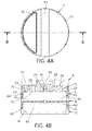
- FIG. 4A is a top view of an herb grinding device
- FIG. 4B is a cross-sectional view of an herb grinding device taken along sectional line B-B in FIG. 4A ;
- FIG. 5A is a top view of a first and second section of an herb grinding device
- FIG. 5B is a cross sectional view of a first and second section of an herb grinding device taken along sectional line A-A of FIG. 5A ;
- FIG. 5C is an enlarged cross sectional view of the circled portion of FIG. 5B ;
- FIG. 6A is a top view of an exploded first and section of an herb grinding device
- FIG. 6B is a cross sectional view of an exploded first and second section of an herb grinding device taken along sectional line C-C of FIG. 6A ;
- FIG. 7A is a top view of a first section of an herb grinding device
- FIG. 7B is a bottom view of a first section of an herb grinding device
- FIG. 7C is a first side view of a first section of an herb grinding device
- FIG. 7D is a second side view of a first section of an herb grinding device
- FIG. 7E is top perspective view of a first section of an herb grinding device
- FIG. 7F is a bottom perspective view of a first section of an herb grinding device
- FIG. 7G is a front perspective view of a tooth of a first section of an herb grinding device
- FIG. 7H is a rear perspective view of a tooth of a first section of an herb grinding device
- FIG. 8A is a top view of a second section of an herb grinding device
- FIG. 8B is a bottom view of a second section of an herb grinding device
- FIG. 8C is a side view of a second section of an herb grinding device
- FIG. 8D is a top perspective view of a second section of an herb grinding device
- FIG. 8E is a bottom perspective view of a second section of an herb grinding device
- FIG. 8F is a front perspective view of a tooth of a second section of an herb grinding device
- FIG. 8G is a rear perspective view of a tooth of a second section of an herb grinding device
- FIG. 9A is a top view of a third section of an herb grinding device
- FIG. 9B is a bottom view of a third section of an herb grinding device
- FIG. 9C is a side view of a third section of an herb grinding device
- FIG. 9D is an exploded view of a third section of an herb grinding device
- FIG. 9E is a perspective view of a third section of an herb grinding device without a screen.
- FIG. 10A is a side view of a fourth section of an herb grinding device
- FIG. 10B is a top view of a fourth section of an herb grinding device
- FIG. 10C is a bottom view of a fourth section of an herb grinding device
- FIG. 10D is a top perspective view of a fourth section of an herb grinding device
- FIG. 10E is a bottom perspective view of a fourth section of an herb grinding device
- FIG. 11 is a perspective view of a second embodiment of an herb grinding device
- FIG. 12 is a top view of a second embodiment of an herb grinding device with a top wall of a first section removed to provide an interior view of the grinding chamber of the herb grinding device;
- FIG. 13A is an upper exploded view of a second embodiment of an herb grinding device
- FIG. 13B is a lower exploded view of a second embodiment of an herb grinding device
- FIG. 14A is a top view of a second embodiment of an herb grinding device
- FIG. 14B is a cross-sectional view of a second embodiment of an herb grinding device taken along sectional line D-D in FIG. 14A ;
- FIG. 15A is a top view of a first and second section of a second embodiment of an herb grinding device
- FIG. 15B is a cross sectional view of a first and second section of a second embodiment of a second embodiment of an herb grinding device taken along sectional line E-E of FIG. 15A ;
- FIG. 15C is an enlarged cross sectional view of the circled portion of FIG. 15B ;
- FIG. 16A is a top view of an exploded first and section of a second embodiment of an herb grinding device
- FIG. 16B is a cross sectional view of an exploded first and second section of a second embodiment of an herb grinding device taken along sectional line F-F of FIG. 16A ;
- FIG. 17A is a top view of a first section of a second embodiment of an herb grinding device
- FIG. 17B is a bottom view of a first section of a second embodiment of an herb grinding device
- FIG. 17C is a first side view of a first section of a second embodiment of an herb grinding device
- FIG. 17D is a second side view of a first section of a second embodiment of an herb grinding device
- FIG. 17E is top perspective view of a first section of a second embodiment of an herb grinding device
- FIG. 17F is a bottom perspective view of a first section of a second embodiment of an herb grinding device
- FIG. 17G is a front perspective view of a tooth of a first section of a second embodiment of an herb grinding device
- FIG. 17H is a rear perspective view of a tooth of a first section of a second embodiment of an herb grinding device
- FIG. 18A is a top view of a second section of a second embodiment of an herb grinding device
- FIG. 18B is a bottom view of a second section of a second embodiment of an herb grinding device
- FIG. 18C is a side view of a second section of a second embodiment of an herb grinding device
- FIG. 18D is a top perspective view of a second section of a second embodiment of an herb grinding device
- FIG. 18E is a bottom perspective view of a second section of a second embodiment of an herb grinding device
- FIG. 18F is a front perspective view of a tooth of a second section of a second embodiment of an herb grinding device
- FIG. 18G is a rear perspective view of a tooth of a second section of a second embodiment of an herb grinding device
- FIG. 19A is a top view of a third section of a second embodiment of an herb grinding device
- FIG. 19B is a bottom view of a third section of a second embodiment of an herb grinding device.
- FIG. 19C is a side view of a third section of a second embodiment of an herb grinding device.
- FIG. 19D is an exploded view of a third section of a second embodiment of an herb grinding device.
- FIG. 19E is a perspective view of a third section of a second embodiment of an herb grinding device without a screen
- FIG. 20A is a side view of a fourth section of a second embodiment of an herb grinding device
- FIG. 20B is a top view of a fourth section of a second embodiment of an herb grinding device
- FIG. 20C is a bottom view of a fourth section of a second embodiment of an herb grinding device
- FIG. 20D is a top perspective view of a fourth section of a second embodiment of an herb grinding device
- FIG. 20E is a bottom perspective view of a fourth section of a second embodiment of an herb grinding device.
- FIG. 21A is a perspective view of a second embodiment of an herb grinding device with bumper rings separated from the herb grinding device;
- FIG. 21B is a perspective view of a second embodiment of an herb grinding device with bumper rings coupled to the first section of the herb grinding device.
- FIG. 21C is a perspective view of a second embodiment of an herb grinding device with bumper rings coupled to the first section of the herb grinding device, the first section being removed from the other sections of the herb grinding device.
- an herb grinding device of this disclosure may have multiple cylindrical sections, wherein rotation of two of the sections produces a shearing and/or grinding action as teeth pass in between one another.
- the floor of the second section may include a series of holes that allow the ground herbs to be separated and be stored in the third section below the second section.
- the third section may include a screen that filters finely ground herbs, and a fourth section separates and stores the finely ground herbs. Greater details and other configurations of each of these sections will be described below.
- one or more of the herb grinding devices contemplated herein are advantageous to conventional herb grinding devices by providing three different coarseness options of ground herbs due to a dual teeth edge design, reducing the force/friction required to grind herbs due to the design of radial cut teeth, increasing longevity of the device due to innovative design of the threading notches that eliminates cross threading, increasing longevity of the device due to the replaceable fine filtering screen and support for the screen by a cross brace support member, and providing a portable solution for users to manually grind small quantities of herbs while addressing all the common pit falls associated with traditional grinders.
- an herb grinding device 2 is relatively lightweight and portable, and yet very strong.
- an herb grinding device 2 may be manufactured from 6061 or 7075 grade aluminum, 304 stainless, or T2 titanium.
- an herb grinding device 2 comprises at least a first section 4 and a second section 6 .
- Other contemplated embodiments may comprise a third section 8 and/or a fourth section 10 , although these sections are not required in all embodiments.
- reference is made in this description and in the figures to substantially cylindrical sections of an herb grinding device 2 it is contemplated that the exterior of the herb grinding device 2 is not always cylindrical and may, instead, comprise any other geometric shapes and configurations.
- FIG. 1 provides a perspective view of a non-limiting embodiment of a herb grinding device 2 comprising a first section 4 coupled to a second section 6 , a third section 8 coupled to the second section 6 opposite the first section 4 , and a fourth section 10 coupled to the third section 8 opposite the second section 6 .
- FIGS. 3A and 3B provide exploded top and bottom perspective views, respectively, and FIG. 4B provides a cross sectional view of non-limiting embodiment of an herb grinding device 2 comprising a first section 4 , a second section 6 , a third section 8 , and a fourth section 10 . Details of each of the sections shall be provided below.
- an herb grinding device 2 comprises a first section 4 rotatably and removably coupled to a second section 6 .
- a first section 4 comprises a substantially cylindrical first section 4 having a cylindrical first cavity 62 within a portion of the cylindrical first section 4 .
- a first section may comprise other geometric configurations on the outside of the first section, and maintain a cylindrical first cavity 62 within a portion of the first section.
- the first cavity 62 may be bordered by circular outer wall 72 and a top surface 58 , and comprise an opening opposite the top surface 58 .
- the first cavity 62 comprises a depth of between approximately 0.25′′ and 0.75′′.
- the outer wall 72 is sized to receive a portion of the second section 6 within the first cavity 62 or, alternatively, fit within a portion of the second section 6 .
- a first section 4 comprises a plurality of teeth 50 .
- the plurality of teeth 50 extend from the top surface 58 of the first section and are positioned to form a plurality of concentric teeth rings 60 , with each concentric teeth ring 60 comprising a plurality of teeth 50 .
- the first section 4 comprises three concentric teeth rings 60 , with each concentric teeth ring 60 comprising four equally spaced apart teeth 50 .
- a first section 4 may comprise any number of concentric teeth rings 60 and any number of teeth 50 within each concentric teeth ring.
- Each concentric teeth ring 60 comprises a center aligned with a center of the first cavity 62 .
- a magnet 64 is positioned at a center of the first cavity 62 of the first section 4 .
- the plurality of teeth 50 within each concentric teeth ring 60 may be aligned with the plurality of teeth 50 within each adjacent teeth ring 60 .
- the four teeth 50 in each concentric ring are aligned with the four teeth in the adjacent concentric teeth ring 60 , each tooth 50 within each concentric teeth ring 60 being approximately 90 degrees from the adjacent teeth of the same concentric teeth ring 60 . That is, the teeth 50 of adjacent teeth rings 60 are aligned, but narrow in radial length towards a center of the first cavity 62 in a pie-shaped configuration. Thus, a pie-shaped configuration of space may exist between aligned teeth 50 .
- each tooth 50 of the first section 4 comprises a circular arced tooth 50 . More particularly, each circular arced tooth 50 may comprise a center point of the arc at a center of first cavity 62 .
- Circular arced teeth 50 are advantageous to conventional teeth because circular arced teeth are extremely strong and unbreakable due to the curvature and elongation of the teeth 50 .
- Conventional teeth are typically post teeth, which are prone to breaking when enough force is applied.
- Circular arced teeth are also more elongated teeth 50 than conventional post teeth, and allow the ground material to essentially roll between the teeth 50 and become compacted, which then allows the material to fall through the holes 24 with less effort.
- each tooth 50 may comprise one or more of the following: a V-shaped protrusion 52 on a first end of the tooth 50 , a crescent shaped recess 56 on a second end of the tooth 50 opposite the first end, and a V-shaped recess 54 on a bottom end of the tooth 50 opposite the top surface 58 .
- the V-shaped recess 54 may comprise an angle of between approximately 30 degrees and 150 degrees.
- a V-shaped recess 54 on a bottom end of the tooth 50 assists in the shearing and/or grinding by allowing the first section 4 to be placed on to the second section 6 without the need to smash it in place.
- V-shaped recess 54 on a bottom end of the tooth 50 also reduces the amount of ground material sticking to the interior of the first cavity 62 and the second cavity 22 by reducing surface area contact.
- each tooth comprises a V-shaped protrusion 52 on a first end of the tooth 50 , a crescent shaped recess 56 on a second end of the tooth 50 opposite the first end, and a V-shaped recess 54 on a bottom end of the tooth 50 opposite the top surface 58 .
- each tooth 50 in each concentric teeth ring 60 extends approximately 30 degrees along the respective teeth ring 60 .
- a width of each tooth of the plurality of teeth 50 may be between approximately 0.050′′ and 0.150′′.
- the V-shaped portion of each recess or protrusion may be sharp and angular or, alternatively, partially rounded.
- each tooth 50 may comprise a radiused edged 78 at a base of the tooth 50 where the tooth 50 intersects the top surface 58 , thus providing additional strength to the tooth 50 .
- rotatable coupling of a first section 4 to a second section 6 is enhanced or strengthened by a magnet 64 at the center of the first cavity 62 , such as but not limited to a neodymium magnet.
- the magnet 64 may be magnetically attracted to metal of the second section 6 or, alternatively a magnet 26 positioned at a center of the second section 6 .
- Magnetic coupling of the first section 4 and the second section 6 is advantageous because it prevents the sections from separating during rotation of the first section and grinding, while still allowing for easy and quickly removal of the first section 4 from the second section 6 to insert herbs into the grinding device 2 .
- each magnet 64 , 26 may be held in place on the respective first section 4 or second section by a magnet boss on each section.
- a magnet boss of the second section 6 is equal distance from the second section floor 20 as a magnet boss of the first section 4 is from the top surface 58 . This allows the magnets 64 , 26 to meet and contact each other a center point between the top surface 58 and the second section floor 20 . Such a configuration inhibits material from getting stuck between the magnets and weakening the magnetic coupling between the magnets 64 , 26 . In other embodiments, any other coupling devices known in the art may be utilized.
- a first section 4 may comprise at least one of a recessed outer cavity 16 , a T-shaped slot 14 , and a plurality of gripping slots 12 .
- the recessed outer cavity 16 is positioned on an outside of the first section 4 opposite the first cavity 62 and may be sized to function as an ash tray on the herb grinding device 2 .
- the recessed outer cavity comprises a width approximately one-third a diameter of the first section 4 .
- a t-shaped slot 14 may be sized to allow for a standard rolling papers sleeve package to be held in place within the T-slot. This allows rolling papers to be dispensed through the top surface of the first section 4 . This helps prevent loss or misplacement of the rolling papers by the user.
- One or more embodiments of a first section 4 further comprise gripping elements, such as but not limited to a plurality of gripping slots 12 on an outer circumference of the first section 4 .
- the gripping slots 12 allow for a more natural grip of the hand and fingers. Thus, a user need apply significantly less pressure when rotating the lid as compared to the conventional knurl style grip.
- an herb grinding device 2 of this disclosure may further comprise a second section 6 rotatably coupled to a first section 4 .
- a second section 6 comprises a substantially cylindrical second section 6 having a cylindrical second cavity 22 within a portion of the cylindrical second section 6 .
- a second section may comprise other geometric configurations on the outside of the second section, and maintain a cylindrical second cavity 22 within a portion of the second section.
- the second cavity 22 may be bordered by annular flange 28 and a second section floor 20 , and comprise an opening opposite the second section floor 20 .
- a second cavity 22 comprises a depth between approximately 0.25′′ and 0.75′′.
- the annular flange 28 is sized to fit within the first cavity 62 and interface with or be adjacent to the outer wall 72 of the first section 72 .
- This configuration allows the first section 4 to rotate freely about the annular flange 28 in either direction.
- This configuration also reduces residue buildup and accumulation because the annular flange 28 fits within the first section 4 . Accordingly, a slight space may exist between the interfaced outer wall 72 and annular flange 28 to allow rotation of the first section 4 relative to the second section 6 .
- the annular flange 28 is sized to receive a portion of the first section 4 to allow rotation of the first section 4 within the second cavity 22 .
- a second section 6 comprises a plurality of teeth 30 .
- the plurality of teeth 30 extend from second section floor 20 within the second cavity 22 of the second section 6 and are positioned to form a plurality of concentric teeth rings 40 , with each concentric teeth ring 40 comprising a plurality of teeth 30 .
- the second section 6 comprises two concentric teeth rings 40 , with each concentric teeth ring 40 comprising four equally spaced apart teeth 30 .
- a second section 6 may comprise any number of concentric teeth rings 40 and any number of teeth 30 within each concentric teeth ring 40 .
- Each concentric teeth ring 40 comprises a center aligned with a center of the second cavity 22 .
- a magnet 26 is positioned at a center of the second cavity 22 of the second section 6 .
- the plurality of teeth 30 within each concentric teeth ring 40 may be aligned with the plurality of teeth 30 within each adjacent teeth ring 40 .
- the four teeth 30 in each concentric ring 40 are aligned with the four teeth 30 in the adjacent concentric teeth ring 40 , each tooth 30 within each concentric teeth ring 40 being approximately 90 degrees from the adjacent teeth of the same concentric teeth ring 40 . That is, the teeth 30 of adjacent teeth rings 40 are aligned, but narrow in radial length towards a center of the second cavity 22 in a pie-shaped configuration. Thus, a pie-shaped configuration of space may exist between aligned teeth 30 .
- each tooth 30 of the second section 6 comprises a circular arced tooth 30 . More particularly, each circular arced tooth 30 may comprise a center point of the arc at a center of second cavity 22 .
- each tooth 30 may comprise one or more of the following: a V-shaped protrusion 32 on a first end of the tooth 30 , a crescent shaped recess 36 on a second end of the tooth 30 opposite the first end, and a V-shaped recess 34 on a top end of the tooth 30 opposite the second section floor 20 .
- a V-shaped recess 34 on a top end of the tooth 30 assists in the shearing and/or grinding by allowing the second section 6 to be placed into the first section 4 without the need to smash it in place.
- the V-shaped recess 34 may comprise an angle of between approximately 30 degrees and 150 degrees. This helps slice down through the unground material rather than just smashing the sections together with brute force.
- the V-shaped recess 34 on a top end of the tooth 30 also reduces the amount of ground material sticking to the interior of the first cavity 62 and the second cavity 22 by reducing surface area contact.
- each tooth 30 comprises a V-shaped protrusion 32 on a first end of the tooth 30 , a crescent shaped recess 36 on a second end of the tooth 30 opposite the first end, and a V-shaped recess 34 on a top end of the tooth 30 opposite the second section floor 20 .
- each tooth 30 in each concentric teeth ring 40 extends approximately 30 degrees along the respective teeth ring 40 . More particularly, a width of each tooth of the plurality of teeth 30 may be between approximately 0.050′′ and 0.150′′.
- the V-shaped portion of each recess or protrusion may be sharp and angular or, alternatively, partially rounded.
- each tooth 30 comprises a radiused edged 78 at a base of the tooth 30 where the tooth 30 intersects the second section floor 20 , thus providing additional strength to the tooth 30 .
- the plurality of teeth 50 of the first section 4 and the plurality of teeth 30 of the second section 6 are positioned on their respective sections such that the V-shaped protrusions 52 of the plurality of teeth 50 of the first section 4 point opposite the V-shaped protrusions 32 of the plurality of teeth 30 of the second section 6 .
- a width of each of the plurality of teeth 30 , 50 of the first section 4 and the second section 6 is equal to a distance between adjacent concentric teeth rings 40 , 60 of the first section 4 and second section 4 .
- a width of each tooth of the plurality of teeth 30 , 50 may comprise a width of approximately 0.10′′.
- a gap or distance between the plurality of teeth 50 on a first concentric teeth ring 60 of the first section 4 and the plurality of teeth 30 on an adjacent first concentric teeth ring 40 of the second section 6 is approximately 0.10′′.
- a gap or distance between the magnet boss of each section is also equal to a width of the plurality of teeth 30 , 50
- a gap or distance between the outer most centric teeth ring is also equal to a width of the plurality of teeth 30 , 50 .
- FIG. 2 depicts one such non-limiting embodiment of an herb grinding device 2 wherein the V-shaped protrusions 32 of the plurality of teeth 30 of the second section 6 point in a counter-clockwise direction, while the V-shaped protrusions 52 of the plurality of teeth 50 of the first section 4 point in a clockwise direction.
- Configuration of the teeth 30 , 50 in this manner allows for three different coarseness consistencies of ground herbs: coarse, medium, and fine.
- a clockwise rotation results in a rough coarseness grind and utilizes the V-shaped protrusions 32 , 52 of the teeth 30 , 50 .
- a counter-clockwise rotation results in a fine coarseness grind and utilizes the crescent recesses 36 , 56 of the teeth 30 , 50 .
- a combination of both counter clockwise and clockwise rotations results in a medium coarseness grind and utilizes both edges of the teeth 30 , 50 . This is unique and different from any other grinder as the traditional grinders only employ one cutting edge, thus resulting in only a single coarseness consistency.
- each second section 6 comprises a plurality of holes 24 in the second section floor 20 .
- the plurality of holes 24 may be configured to allow ground herbs to be separated and fall through to the third section 8 and/or fourth section 10 typically positioned below the second section 6 .
- the plurality of holes 24 are arranged in a plurality of concentric hole rings 29 each comprising a plurality of holes 24 .
- the second section 6 comprises three concentric hole rings 29 each comprising a plurality of holes 24 . More particularly, the plurality of concentric teeth rings 40 may be alternately positioned between the plurality of concentric hole rings 29 .
- the non-limiting embodiment depicted in FIGS. 8D & 8E comprises the following concentric rings, working outward from the center magnet 26 of the second section floor: a first concentric hole ring between the center magnet 26 and a first concentric teeth ring, the first concentric teeth ring between the first concentric hole ring and the second concentric hole ring, the second concentric hole ring between the first concentric teeth ring and a second concentric teeth ring, the second concentric teeth ring between the second concentric hole ring and a third concentric hole ring, and the third concentric teeth ring between the second concentric teeth ring and the annular flange 28 .
- Other embodiments may additional or few alternating concentric teeth and hole rings.
- the plurality of concentric hole rings 29 of the second section 6 is positioned to align with the plurality of concentric teeth rings 60 of the first section 4 . More particularly, the teeth 50 of the first section 4 may be perfectly positioned on a centerline of a hole 24 of a concentric hole ring 29 . This allows for the ground material to pass through the holes in a more efficient manner and allows for creation of a pinch point during grinding.
- FIG. 2 depicts a non-limiting embodiment of an herb grinding device 2 with a top surface 58 removed to view the grinding chamber 85 of the herb grinding device 2 .
- a distance between each concentric teeth ring 40 of the second section 6 and an adjacent concentric teeth ring 60 of the first section 4 is between approximately 0.050′′ and 0.150′′ inches when the first section 4 and the second section 6 are rotatably coupled together.
- the aligned and circular arced teeth 30 , 50 reduce the shearing and/or grinding friction of conventional systems by allowing smooth lid rotation while slicing the material. Conventional grinding teeth mash and tear, while the circular arced teeth 30 , 50 contemplated herein shear and slice, resulting in reduced friction.
- Such a configuration also helps maintain the integrity of tricombs found on herbal material, which results in a more desirable grinding and/or shearing methodology as it properly prepares the herbs for use without destroying them.
- Embodiments of a second section 6 may comprise a plurality of holes 24 of any of a number of shapes and configurations.
- each of the plurality of holes 24 may be substantially square shaped, including having rounded corners on the square hole.
- Square shaped holes 24 may be advantageous to other shapes by allowing the teeth 30 , 50 edges to create a pinch point against the square shaped holes 24 to further reduce friction and increase grinder efficiency.
- Conventional grinders utilize round holes or slots, which do not help the shearing and grinding efficiency because a pinch point is non-existent on a curved or rounded hole.
- the plurality of holes 24 may be positioned on the second section floor 20 such that a corner 25 of each of the plurality of holes is pointing or otherwise directed to a center, such as the center magnet 26 , of the second section floor 20 .
- the plurality of holes 24 may comprise other shapes and configurations, such as but not limited to diamond, star, pentagon, hexagon, or triangle.
- FIGS. 4B and 5C depict cross sectional views that include a grinding chamber 85 formed by the alignment of a first cavity 62 of a first section 2 and a second cavity 22 of a second section 6 .
- the first cavity 62 and the second cavity 22 are sized such that a small gap 82 exists between the bottom of the plurality of teeth 50 of the first section 4 and the second section floor 2 , and a small gap 80 exists between the top of the plurality of teeth 30 of the second section 6 .
- each gap 80 , 82 is approximately 0.010′′.
- the gaps 80 , 82 also reduces the build up and accumulation of residue, which eventually clogs the grinding chamber 85 . Furthermore, the gaps 80 , 82 may also ensure the magnets 26 , 64 holding the first section 4 and the second section 6 together remain coupled, thus ensuring a strong magnetic coupling or seal.
- the teeth of conventional grinders drag directly on the interior cavity floors, which result in the employment of a thick plastic lid ring to elevate the teeth from the floor. This, in turn, does not allow for a magnetic coupling and results in a weaker seal or coupling of the section.
- configurations contemplated herein eliminate the need for a thick plastic lid ring typically employed on all other grinders.
- a second section 6 is removably coupled to a third section 8 .
- a second section 6 is threadedly and removably coupled to a third section 8 .
- a second section 6 may be threadedly coupled to a third section 8 with a plurality of threading notches 66 .
- the non-limiting embodiment depicted in FIGS. 8B and 8E comprises four relief threading notches 66 configured to engage with relief threading notches 38 of the third section 8 .
- the threading notches 66 of the second section 6 may be positioned on an inner surface of the second section 6 below the second section floor 20 and opposite the second cavity 22 , while the threading notches 38 of the third section 8 may be positioned on at outer surface of an annular flange of the third section 8 that fits within the second section 6 . In other embodiments, the threading notches 66 of the second section 6 may be positioned on an outer surface that fits within a portion of the third section 8 . Removably coupling via the four threading notches 66 , 38 allows for separation or coupling of the second section 6 and the third section 8 quicker than a conventional thread that has to be unscrewed and rotated multiple times before being completely coupled or uncoupled.
- the threading notches 38 , 66 comprise a low threads per inch (TPI), such as but not limited to a 12-6 TPI.
- TPI threads per inch
- the female side threading notches contemplated in this disclosure is separated into eight segments that alternate evenly between thread-gap-thread-gap. The gaps in the female connection of the quick lock thread serve as relief for coupling the male side of the adjacent section.
- FIGS. 9A-9E depict various view of a non-limiting embodiment of a third section 8 of an herb grinding device 2 .
- a third section 8 may be configured to filter finely ground herbs.
- a third section 8 comprises a channel 70 extending through a cylindrical third section 8 and on or more support arms 68 extending across the channel 70 .
- the one or more support arms 68 comprise a cross brace support arms 68 .
- Cross brace support arms 68 may be configured to support a bottom surface of a screen 42 coupled to the cross brace support arms 68 with a screw 82 such that the screen 42 is positioned within the channel 70 .
- FIG. 9D provides an exploded perspective view of a third section 8 comprises a screen 42
- FIG. 9D provides an exploded perspective view of a third section 8 comprises a screen 42
- FIG. 3A provides a perspective view of a third section 8 with a screen 42 coupled to the cross brace support arms 68 in the third section 8 .
- the screen may comprise one of a fine, medium, or coarse woven mesh, stainless steel, or titanium.
- An outer edge of a screen 42 may be held in place within the third section 8 with a small groove on an inner surface of the channel 70 just above the cross brace support arms 68 .
- Utilizing one or more support arms 68 such as cross brace support arms 68 is advantageous to conventional devices because the support arms 68 support the screen 42 , rather than unsupported screens stretched across the device like a drum in conventional systems.
- Such conventional mounting of a screen results in tearing and stretching of the screen over time.
- support of the screen 42 with support arms 68 prevents stretch and tearing, and allows for easy replacement of the screen 42 .
- a third section 8 may comprise threading notches 38 on an annular flange of the third section 8 for coupling of the third section 8 to a second section 6 .
- a third section 8 is threadedly and removably coupled to a fourth section 10 .
- a third section 8 may be threadedly coupled to a fourth section 10 with a plurality of threading notches 74 .
- the non-limiting embodiment depicted in FIG. 9B comprises four relief threading notches 74 configured to engage with relief threading notches 48 of the fourth section 10 .
- the threading notches 74 of the third section 8 may be positioned on an inner surface of the third section 8 below the support arms 68 , while the threading notches 48 of the fourth section 10 may be positioned on at outer surface of an annular flange of the fourth section 10 that fits within the third section 8 . In other embodiments, the threading notches 74 of the third section 8 may be positioned on an outer surface that fits within a portion of the fourth section 10 . Removably coupling via the four threading notches 74 , 48 allows for separation or coupling of the third section 8 and the fourth section 10 quicker than a conventional thread that has to be unscrewed and rotated multiple times before being completely coupled or uncoupled.
- the threading notches 74 , 48 comprise a low threads per inch (TPI), such as but not limited to a 12-6 TPI.
- FIGS. 10A-E depict various views of a non-limiting embodiment of a fourth section 10 of an herb grinding device.
- a fourth section 10 may be configured to store finely ground particles and/or pollen.
- a fourth section 10 is configured to be removably coupled to a third section 8 .
- the fourth section 10 may couple to the third section 8 with threading notches 48 .
- a fourth section 10 comprises a collection cavity 44 .
- the collection cavity 44 is configured to collect the grindings of herbs ground in the grinding chamber 85 of the first section 4 and the second section 6 .
- the collection cavity 44 comprises a radiused edge 46 .
- the radiused edge 46 of the collection cavity 44 allow for easy removal of finely filtered particles and solves the traditional problem of particles getting trapped in the corners of a collection cavity.
- This configuration allows for a standard guitar pick to contour the radiused edge 46 of the collection cavity 44 to assist in fine pollen removal. It is also configured for use of a finger to remove or scoop the particles from the collection cavity 44 .
- the fourth section 10 comprising a collection cavity 44 may be removably coupled to the second section 6 comprising a second section floor as previously described. That is, in some embodiments, a third section 8 is not necessary. Coupling of the fourth section 10 to the second section 6 may be similar to the coupling of a third section 8 to a second section 6 .
- FIGS. 11-21 depict various views of another non-limiting embodiment of an herb-grinding device.
- an herb grinding device 102 is relatively lightweight and portable, and yet very strong.
- an herb grinding device 102 may be manufactured from 6061 or 7075 grade aluminum, 304 stainless, or T2 titanium.
- an herb grinding device 102 comprises at least a first section 104 and a second section 106 .
- Other contemplated embodiments may comprise a third section 108 and/or a fourth section 110 , although these sections are not required in all embodiments.
- FIG. 11 provides a perspective view of a non-limiting embodiment of a herb grinding device 102 comprising a first section 104 coupled to a second section 106 , a third section 108 coupled to the second section 106 opposite the first section 104 , and a fourth section 110 coupled to the third section 108 opposite the second section 106 .
- FIGS. 13A and 13B provide exploded top and bottom perspective views, respectively, and FIG.
- 14B provides a cross sectional view of non-limiting embodiment of an herb grinding device 102 comprising a first section 104 , a second section 106 , a third section 108 , and a fourth section 110 . Details of each of the sections shall be provided below.
- an herb grinding device 102 comprises a first section 104 rotatably and removably coupled to a second section 106 .
- a first section 104 comprises a substantially cylindrical first section 104 having a cylindrical first cavity 162 within a portion of the cylindrical first section 104 .
- a first section may comprise other geometric configurations on the outside of the first section, and maintain a cylindrical first cavity 162 within a portion of the first section.
- the first cavity 162 may be bordered by circular outer wall 172 and a top surface 158 , and comprise an opening opposite the top surface 158 .
- the first cavity 162 comprises a depth of between approximately 0.25′′ and 0.75′′.
- the outer wall 172 is sized to receive a portion of the second section 106 within the first cavity 162 or, alternatively, fit within a portion of the second section 106 .
- a first section 104 comprises a plurality of teeth 150 .
- the plurality of teeth 150 extend from the top surface 158 of the first section and are positioned to form a plurality of concentric teeth rings 160 , with each concentric teeth ring 160 comprising a plurality of teeth 150 .
- the first section 104 comprises four concentric teeth rings 60 , with each concentric teeth ring 160 comprising four equally spaced apart teeth 150 .
- a first section 104 may comprise any number of concentric teeth rings 160 and any number of teeth 150 within each concentric teeth ring 160 .
- Each concentric teeth ring 160 comprises a center aligned with a center of the first cavity 162 .
- a magnet 164 is positioned at a center of the first cavity 162 of the first section 104 .
- the magnet 164 may be surrounded by a toothed magnet mount that aids in the grinding of herbs within the cavity.
- the plurality of teeth 150 within each concentric teeth ring 160 may be aligned with the plurality of teeth 150 within each adjacent teeth ring 160 .
- the four teeth 150 in each concentric ring 160 are aligned with the four teeth in the adjacent concentric teeth ring 160 , the center of each tooth 150 within each concentric teeth ring 160 being approximately 90 degrees from the center of adjacent teeth of the same concentric teeth ring 160 . That is, the teeth 150 of adjacent teeth rings 160 are aligned, but narrow in radial length towards a center of the first cavity 162 in a pie-shaped configuration. Thus, a pie-shaped configuration of space may exist between aligned teeth 150 . In other embodiments, such as the non-limiting embodiment depicted in FIG.
- the plurality of teeth 150 within each concentric teeth ring 160 are not aligned but instead offset from a plurality of teeth 150 of an adjacent concentric teeth ring 160 .
- the plurality of teeth 150 within each concentric teeth ring 160 are offset from a plurality of teeth 150 of an adjacent concentric teeth ring 160 by between approximately 15 to approximately 25 degrees, approximately 20 to approximately 35 degrees, approximately 40 to approximately 50 degrees, approximately 11.25 degrees, approximately 22.5 degrees, or approximately 30 degrees, approximately 45 degrees.
- each tooth of the first section 104 is comprises a tooth 50 described elsewhere in this document.
- each tooth 150 of the first section 104 comprises a substantially planar tooth 150 .
- Substantially planar teeth 50 are advantageous to conventional teeth because substantially planar teeth are extremely strong and unbreakable due to the elongation of the substantially planar teeth 150 .
- Conventional teeth are typically post teeth, which are prone to breaking when enough force is applied.
- Substantially planar teeth 150 are also more elongated teeth 150 than conventional post teeth, and allow the ground material to essentially roll between the teeth 150 and become compacted, which then allows the material to fall through the holes 124 with less effort.
- FIGS. 17G and 17H depict close up views of non-limiting embodiments of a substantially planar tooth 150 of the first section 104 .
- each tooth 150 may comprise one or more of the following: a V-shaped protrusion 152 on a first end of the tooth 150 , a V-shaped protrusion 156 on a second end of the tooth 150 opposite the first end, and a V-shaped protrusion 154 on a bottom end of the tooth 150 opposite the top surface 158 .
- the V-shaped protrusion 154 may comprise an angle of between approximately 30 degrees and 150 degrees.
- a V-shaped protrusion 154 on a bottom end of the tooth 150 assists in the shearing and/or grinding by allowing the first section 104 to be placed on to the second section 106 without the need to smash it in place. This helps slice down through the unground material rather than just smashing the sections together with brute force.
- the V-shaped protrusion 154 on a bottom end of the tooth 150 also reduces the amount of ground material sticking to the interior of the first cavity 162 and the second cavity 122 by reducing surface area contact.
- the substantially planar teeth may comprise the V-shaped or crescent-shaped recesses described in other teeth elsewhere in this document.
- each tooth comprises a V-shaped protrusion 152 on a first end of the tooth 150 , a V-shaped protrusion 156 on a second end of the tooth 150 opposite the first end, and a V-shaped protrusion 154 on a bottom end of the tooth 150 opposite the top surface 158 .
- each tooth 150 in each concentric teeth ring 160 comprises substantially equal dimensions, while in other embodiments, teeth 150 increase in size as the concentric teeth ring 160 is further from the center.
- Each tooth of the plurality of teeth 150 may comprise a length of approximately 0.25′′, approximately 0.33′′, approximately 0.50′′, approximately 0.66′′, approximately 0.75′′, or approximately 1.00′′.
- a width of each tooth of the plurality of teeth 150 may be between approximately 0.050′′ and 0.150′′.
- the V-shaped portion of each protrusion may be sharp and angular.
- each tooth 150 may comprise a radiused edged 178 at a base of the tooth 150 where the tooth 150 intersects the top surface 158 , thus providing additional strength to the tooth 150 .
- rotatable coupling of a first section 4 to a second section 106 is enhanced or strengthened by a magnet 164 at the center of the first cavity 162 , such as but not limited to a neodymium magnet.
- the magnet 164 may be magnetically attracted to metal of the second section 106 or, alternatively a magnet 126 positioned at a center of the second section 106 .
- Magnetic coupling of the first section 104 and the second section 106 is advantageous because it prevents the sections from separating during rotation of the first section and grinding, while still allowing for easy and quickly removal of the first section 104 from the second section 6 to insert herbs into the grinding device 102 .
- each magnet 164 , 126 may be held in place on the respective first section 104 or second section by a magnet boss on each section.
- the magnet boss may include teeth to aid in grinding.
- a magnet boss of the second section 106 is equal distance from the second section floor 120 as a magnet boss of the first section 104 is from the top surface 158 . This allows the magnets 164 , 126 to meet and contact each other a center point between the top surface 158 and the second section floor 120 .
- Such a configuration inhibits material from getting stuck between the magnets and weakening the magnetic coupling between the magnets 164 , 126 .
- any other coupling devices known in the art may be utilized.
- a first section 104 may comprise at least one of a recessed outer cavity 116 , a T-shaped slot 114 , and a plurality of grips 112 .
- the recessed outer cavity 116 is positioned on an outside surface 103 of the first section 104 opposite the first cavity 162 and may be sized to function as an ash tray on the herb grinding device 102 .
- the recessed outer cavity comprises a width approximately one-third a diameter of the first section 104 .
- 17A comprises only a single recessed outer cavity 116 , it is contemplated that some embodiments may comprise two recessed outer cavities 116 , with a T-shaped slot 114 being positioned between the two recessed outer cavities 116 .
- a t-shaped slot 114 may be sized to allow for a standard rolling papers sleeve package to be held in place within the T-slot 114 .
- the T-slot may comprise convex top surface extending toward one another. This allows rolling papers to be dispensed through the top surface of the first section 104 and helps prevent loss or misplacement of the rolling papers by the user.
- first section 104 further comprise a plurality of grips 112 on an outer circumference of the first section 104 .
- each of the plurality of grips 112 may comprise alternating grip protrusions 113 and grip recesses 111 positioned axially along an outer perimeter 101 of the first section 104 .
- each of the first 104 , second 106 , third 108 , and fourth 110 sections each comprise a plurality of grips 112 extending axially along an outer perimeter 101 of each respective section.
- the plurality of grips 112 on the second 106 , third 108 , and fourth 108 sections may align axially when the male lock notch 133 of the third section 108 is engaged with the female lock notch 166 of the second section 106 and the male lock notch 148 of the fourth section 110 is engaged with the female lock notch 174 of the third section 108 .
- the grips 112 allow for a more natural grip of the hand and fingers. Thus, a user need apply significantly less pressure when rotating the lid as compared to the conventional knurl style grip.
- an herb grinding device 102 of this disclosure may further comprise a second section 106 rotatably coupled to a first section 104 .
- a second section 106 comprises a substantially cylindrical second section 106 having a cylindrical second cavity 122 within a portion of the cylindrical second section 106 .
- a second section may comprise other geometric configurations on the outside of the second section, and maintain a cylindrical second cavity 122 within a portion of the second section.
- the second cavity 122 may be bordered by annular flange 128 and a second section floor 120 , and comprise an opening opposite the second section floor 120 .
- a second cavity 122 comprises a depth between approximately 0.25′′ and 0.75′′.
- the annular flange 128 according to some aspects is sized to fit within the first cavity 162 and interface with or be adjacent to the outer wall 172 of the first section 104 . This configuration allows the first section 104 to rotate freely about the annular flange 128 in either direction. This configuration also reduces residue buildup and accumulation because the annular flange 128 fits within the first section 104 . Accordingly, a slight space may exist between the interfaced outer wall 172 and annular flange 128 to allow rotation of the first section 104 relative to the second section 106 . In other embodiments, the annular flange 128 is sized to receive a portion of the first section 104 to allow rotation of the first section 104 within the second cavity 122 .
- a second section 106 comprises a plurality of teeth 130 .
- the plurality of teeth 130 extend from second section floor 120 within the second cavity 122 of the second section 106 and are positioned to form a plurality of concentric teeth rings 140 , with each concentric teeth ring 140 comprising a plurality of teeth 130 .
- the second section 106 comprises three concentric teeth rings 140 , with each concentric teeth ring 140 comprising four equally spaced apart teeth 130 .
- a second section 106 may comprise any number of concentric teeth rings 140 and any number of teeth 130 within each concentric teeth ring 140 .
- Each concentric teeth ring 140 comprises a center aligned with a center of the second cavity 122 .
- a magnet 126 is positioned at a center of the second cavity 122 of the second section 106 .
- the plurality of teeth 130 within each concentric teeth ring 140 may be aligned with the plurality of teeth 130 within each adjacent teeth ring 140 .
- four teeth 130 in each concentric ring 140 may be aligned with the four teeth 130 in the adjacent concentric teeth ring 140 , each tooth 130 within each concentric teeth ring 140 being approximately 90 degrees from the adjacent teeth of the same concentric teeth ring 140 .
- the teeth 130 of adjacent teeth rings 140 are aligned, but narrow in length towards a center of the second cavity 122 in a pie-shaped configuration.
- a pie-shaped configuration of space may exist between aligned teeth 130 .
- the plurality of teeth 130 within each concentric teeth ring 140 are not aligned but instead offset from a plurality of teeth 130 of an adjacent concentric teeth ring 140 .
- the plurality of teeth 130 within each concentric teeth ring 140 are offset from a plurality of teeth 130 of an adjacent concentric teeth ring 140 by between approximately 15 to approximately 25 degrees, approximately 20 to approximately 35 degrees, approximately 40 to approximately 50 degrees, approximately 11.25 degrees, approximately 22.5 degrees, or approximately 30 degrees, approximately 45 degrees.
- each tooth 130 of the second section 106 comprises a substantially planar tooth 130 .
- each tooth 130 may comprise one or more of the following: a V-shaped protrusion 132 on a first end of the tooth 130 , a V-shaped protrusion 136 on a second end of the tooth 130 opposite the first end, and a V-shaped protrusion 134 on a top end of the tooth 130 opposite the second section floor 120 .
- a V-shaped protrusion 134 on a top end of the tooth 130 assists in the shearing and/or grinding by allowing the second section 106 to be placed into the first section 104 without the need to smash it in place.
- the V-shaped protrusion 134 may comprise an angle of between approximately 30 degrees and 150 degrees. This helps slice down through the unground material rather than just smashing the sections together with brute force.
- the V-shaped protrusion 134 on a top end of the tooth 130 also reduces the amount of ground material sticking to the interior of the first cavity 162 and the second cavity 122 by reducing surface area contact.
- each tooth 130 comprises a V-shaped protrusion 132 on a first end of the tooth 130 , a V-shaped protrusion 136 on a second end of the tooth 130 opposite the first end, and a V-shaped protrusion 134 on a top end of the tooth 130 opposite the second section floor 120 .
- each tooth 130 in each concentric teeth ring 140 comprises substantially equal dimensions, while in other embodiments, teeth 130 increase in size as the concentric teeth ring 140 is further from the center.
- Each tooth of the plurality of teeth 130 may comprise a length of approximately 0.25′′, approximately 0.33′′, approximately 0.50′′, approximately 0.66′′, approximately 0.75′′, or approximately 1.00′′.
- a width of each tooth of the plurality of teeth 130 may be between approximately 0.050′′ and 0.150′′.
- the V-shaped portion of each protrusion may be sharp and angular.
- each tooth 130 comprises a radiused edged 178 at a base of the tooth 130 where the tooth 30 intersects the second section floor 120 , thus providing additional strength to the tooth 130 .
- a width of each of the plurality of teeth 130 , 150 of the first section 104 and the second section 106 is equal to a distance between adjacent concentric teeth rings 140 , 160 of the first section 104 and second section 106 .
- a width of each tooth of the plurality of teeth 130 , 150 may comprise a width of approximately 0.10′′.
- a gap or distance between the plurality of teeth 150 on a first concentric teeth ring 160 of the first section 104 and the plurality of teeth 130 on an adjacent first concentric teeth ring 140 of the second section 106 is approximately 0.10′′.
- a gap or distance between the magnet boss of each section is also equal to a width of the plurality of teeth 130 , 150
- a gap or distance between the outer most centric teeth ring is also equal to a width of the plurality of teeth 130 , 150 .
- rotatable coupling of a first section 104 to a second section 106 is enhanced or strengthened by a magnet 126 at the center of the second cavity 122 .
- the magnet 126 may be magnetically attracted to metal of the first section 104 or, alternatively, a magnet 164 positioned at a center of the first section 104 .
- each second section 106 comprises a plurality of holes 124 in the second section floor 120 .
- the plurality of holes 124 may be configured to allow ground herbs to be separated and fall through to the third section 108 and/or fourth section 110 typically positioned below the second section 106 .
- the plurality of holes 214 are arranged in a plurality of concentric hole rings 129 each comprising a plurality of holes 124 .
- the second section 106 comprises four concentric hole rings 129 each comprising a plurality of holes 124 . More particularly, the plurality of concentric teeth rings 140 may be alternately positioned between the plurality of concentric hole rings 129 .
- the non-limiting embodiment depicted in FIGS. 18D & 18E comprises the following concentric rings, working outward from the center magnet 126 of the second section floor: a first concentric hole ring between the center magnet 126 and a first concentric teeth ring, the first concentric teeth ring between the first concentric hole ring and the second concentric hole ring, the second concentric hole ring between the first concentric teeth ring and a second concentric teeth ring, the second concentric teeth ring between the second concentric hole ring and a third concentric hole ring, and the third concentric teeth ring between the second concentric teeth ring and the annular flange 128 .
- Other embodiments may additional or few alternating concentric teeth and hole rings.
- the plurality of concentric hole rings 129 of the second section 106 is positioned to align with the plurality of concentric teeth rings 160 of the first section 104 . More particularly, the teeth 150 of the first section 104 may be perfectly positioned on a centerline of a hole 124 of a concentric hole ring 129 . This allows for the ground material to pass through the holes in a more efficient manner and allows for creation of a pinch point during grinding.
- FIG. 12 depicts a non-limiting embodiment of an herb grinding device 102 with a top surface 158 removed to view the grinding chamber 185 of the herb grinding device 102 . By way of example and not limitation, FIG.
- each of the four concentric teeth rings 160 of the first section 104 aligning with a different one of the plurality of concentric hole rings 129 of the second section 106 .
- a distance between each concentric teeth ring 140 of the second section 106 and an adjacent concentric teeth ring 160 of the first section 104 is between approximately 0.050′′ and 0.150′′ inches when the first section 104 and the second section 106 are rotatably coupled together.
- the aligned and planar teeth 130 , 150 reduce the shearing and/or grinding friction of conventional systems by allowing smooth lid rotation while slicing the material. Conventional grinding teeth mash and tear, while the planar teeth 30 , 50 contemplated herein shear and slice, resulting in reduced friction.
- Such a configuration also helps maintain the integrity of tricombs found on herbal material, which results in a more desirable grinding and/or shearing methodology as it properly prepares the herbs for use without destroying them.
- Embodiments of a second section 106 may comprise a plurality of holes 124 of any of a number of shapes and configurations.
- each of the plurality of holes 124 may be substantially isosceles trapezoidal in shape with rounded corners.
- substantially isosceles trapezoidal in shape means that each hole 124 may comprise straight sides and angled corners or, alternatively, the each hole 124 may comprise a generally isosceles trapezoid shape with rounded corners and/or rounded or curved sides.
- Each of the plurality of holes 124 may be positioned such that a longest side 127 of the hole is distal the center of the second cylindrical section floor 120 relative to other sides of the hole.
- a shortest side 125 of the hole is proximate a center of the second cylindrical section floor 120 and a longest side 127 of the hole is distal the center of the second cylindrical section floor 120 .
- the plurality of holes may be substantially triangular in shape, with a point of the triangle distal the center and leg of the triangle proximate the center of the second cylindrical section floor 120 .
- the plurality of holes may comprise a shape similar to holes described elsewhere in this document. These shaped holes are advantageous to conventional holes in conventional grinders. Conventional grinders utilize round holes or slots, which do not help the shearing and grinding efficiency because a pinch point is non-existent on a curved or rounded hole.
- FIGS. 14B and 15C depict cross sectional views that include a grinding chamber 185 formed by the alignment of a first cavity 162 of a first section 102 and a second cavity 122 of a second section 106 .
- the first cavity 162 and the second cavity 122 are sized such that a small gap 182 exists between the bottom of the plurality of teeth 150 of the first section 104 and the second section floor 102 , and a small gap 180 exists between the top of the plurality of teeth 130 of the second section 106 .
- each gap 180 , 182 is approximately 0.010′′.
- Such a configuration allows for a shearing and grinding of herbs within a grinding chamber 185 as a first section 104 is rotated relative to a second section 106 .
- the gaps 180 , 182 also reduces the build up and accumulation of residue, which eventually clogs the grinding chamber 185 .
- the gaps 180 , 182 may also ensure the magnets 126 , 164 holding the first section 104 and the second section 106 together remain coupled, thus ensuring a strong magnetic coupling or seal.
- the teeth of conventional grinders drag directly on the interior cavity floors, which result in the employment of a thick plastic lid ring to elevate the teeth from the floor. This, in turn, does not allow for a magnetic coupling and results in a weaker seal or coupling of the section.
- configurations contemplated herein eliminate the need for a thick plastic lid ring typically employed on all other grinders.
- a second section 106 is removably coupled to a third section 108 .
- a second section 106 may be coupled to a third section 108 with a plurality of lock notches 166 .
- a male lock notch may comprise an angled tab protruding from annular flange, while a female lock notch may comprise an angled recess complementary to the male lock notch and on an inner surface of the section.
- the non-limiting embodiment depicted in FIGS. 18B and 18E comprises four female lock notches 166 configured to engage with male lock notches 138 of the third section 108 .
- the female lock notches 166 of the second section 106 may be positioned on an inner surface of the second section 106 below the second section floor 120 and opposite the second cavity 122 , while the male lock notches 138 of the third section 108 may be positioned on at outer surface of an annular flange of the third section 108 that fits within the second section 106 . In other embodiments, the lock notches 166 of the second section 106 may be positioned on an outer surface that fits within a portion of the third section 108 . Removably coupling via the four lock notches 166 , 138 allows for separation or coupling of the second section 106 and the third section 108 quicker than a conventional thread that has to be unscrewed and rotated multiple times before being completely coupled or uncoupled. Sections may be coupled or uncoupled with a simple one-quarter turn of one of the sections.
- FIGS. 19A-19E depict various view of a non-limiting embodiment of a third section 108 of an herb grinding device 102 .
- a third section 108 may be configured to filter finely ground herbs.
- a third section 108 comprises a channel 170 extending through a cylindrical third section 108 and on or more support arms 168 extending across the channel 170 .
- the one or more support arms 168 comprise a support arms 68 spiraling out from the center of the channel 170 .
- Support arms 168 may be configured to support a bottom surface of a screen 142 coupled to the support arms 168 with a screw 182 such that the screen 142 is positioned within the channel 170 .
- FIG. 19D provides an exploded perspective view of a third section 108 comprises a screen 142
- FIG. 13A provides a perspective view of a third section 108 with a screen 142 coupled to the cross brace support arms 68 in the third section 108
- the screen may comprise one of a fine, medium, or coarse woven mesh, stainless steel, or titanium.
- An outer edge of a screen 142 may be held in place within the third section 108 with a small groove on an inner surface of the channel 170 just above the cross brace support arms 168 .
- Utilizing one or more support arms 168 such as support arms 168 is advantageous to conventional devices because the support arms 168 support the screen 142 , rather than unsupported screens stretched across the device like a drum in conventional systems.
- Such conventional mounting of a screen results in tearing and stretching of the screen over time.
- support of the screen 142 with support arms 168 prevents stretch and tearing, and allows for easy replacement of the screen 142 .
- a third section 108 may comprise lock notches 138 on an annular flange of the third section 108 for coupling of the third section 108 to a second section 6 .
- a third section 108 is removably coupled to a fourth section 110 .
- a third section 108 may be coupled to a fourth section 110 with a plurality of lock notches 174 .
- the non-limiting embodiment depicted in FIG. 19B comprises four lock notches 174 configured to engage with lock notches 148 of the fourth section 10 .
- the lock notches 174 of the third section 108 may be positioned on an inner surface of the third section 108 below the support arms 168 , while the lock notches 148 of the fourth section 110 may be positioned on at outer surface of an annular flange of the fourth section 110 that fits within the third section 108 . In other embodiments, the lock notches 174 of the third section 108 may be positioned on an outer surface that fits within a portion of the fourth section 110 . Removably coupling via the four lock notches 174 , 148 allows for separation or coupling of the third section 108 and the fourth section 110 quicker than a conventional thread that has to be unscrewed and rotated multiple times before being completely coupled or uncoupled. Sections may be coupled or uncoupled with a simple one-quarter turn of one of the sections.
- FIGS. 20A-E depict various views of a non-limiting embodiment of a fourth section 110 of an herb grinding device 102 .
- a fourth section 110 may be configured to store finely ground particles and/or pollen.
- a fourth section 110 is configured to be removably coupled to a third section 108 .
- the fourth section 110 may couple to the third section 108 with lock notches 148 .
- a fourth section 110 comprises a collection cavity 144 .
- the collection cavity 144 is configured to collect the grindings of herbs ground in the grinding chamber 185 of the first section 104 and the second section 106 .
- the collection cavity 144 comprises a radiused edge 146 .
- the radiused edge 146 of the collection cavity 144 allow for easy removal of finely filtered particles and solves the traditional problem of particles getting trapped in the corners of a collection cavity. This configuration allows for a standard guitar pick to contour the radiused edge 146 of the collection cavity 144 to assist in fine pollen removal. It is also configured for use of a finger to remove or scoop the particles from the collection cavity 144 . It is further contemplated that the fourth section 110 comprising a collection cavity 144 may be removably coupled to the second section 106 comprising a second section floor as previously described. That is, in some embodiments, a third section 1088 is not necessary. Coupling of the fourth section 110 to the second section 106 may be similar to the coupling of a third section 108 to a second section 106 .
- FIG. 21A shows a non-limiting embodiment of an herb grinding device 102 having two bumper rings 200 separated from the body of the herb grinding device 102
- FIGS. 21B and 21C shows a non-limiting embodiment of an herb grinding device 102 with two bumper rings 200 removably coupled to the first section 104 of the herb grinding device 102
- the bumper rings 200 comprise rubber and/or elastic O-rings sized wrap around any of the four section of the herb grinding device 102 and fit within the recesses 111 of the grips 112 extending axially along an outer circumference of the respective section or sections.
- the bumper rings 200 When removably coupled to the first section 102 , the bumper rings 200 enable a user to remove the first section 104 and tap it against the other sections of the herb grinding device 102 or other surfaces, allowing stubborn product to fall through the holes 124 and the pollen screen 142 without damaging the exterior of the herb grinding device 102 . While FIGS. 21B-21C show the bumper rings 200 removably coupled to the first section 104 , it is contemplated that the bumper rings 200 are size to stretch around and removably couple to any of the first section 104 d , the second section 106 , the third section 108 , and/or the fourth section 110 .
- implementations are not limited to the specific components disclosed herein, as virtually any components consistent with the intended operation of a method and/or system implementation for herb grinding devices may be utilized. Accordingly, for example, although particular herb grinding devices may be disclosed, such components may comprise any shape, size, style, type, model, version, class, grade, measurement, concentration, material, weight, quantity, and/or the like consistent with the intended operation of a method and/or system implementation for an herb grinding device may be used.
Abstract
Description
Claims (20)
Priority Applications (1)
| Application Number | Priority Date | Filing Date | Title |
|---|---|---|---|
| US14/838,188 US9757733B1 (en) | 2014-04-13 | 2015-08-27 | Herb grinding device |
Applications Claiming Priority (8)
| Application Number | Priority Date | Filing Date | Title |
|---|---|---|---|
| US201461978919P | 2014-04-13 | 2014-04-13 | |
| US201462042746P | 2014-08-27 | 2014-08-27 | |
| US29/511,180 USD755022S1 (en) | 2014-12-08 | 2014-12-08 | Herb grinding device |
| US29/511,178 USD755584S1 (en) | 2014-12-08 | 2014-12-08 | Herb grinding device |
| US29/511,175 USD761064S1 (en) | 2014-12-08 | 2014-12-08 | Herb grinding device |
| US29/520,464 USD759438S1 (en) | 2014-12-08 | 2015-03-13 | Herb grinding device |
| US14/681,808 US9681777B1 (en) | 2014-04-13 | 2015-04-08 | Herb grinding device |
| US14/838,188 US9757733B1 (en) | 2014-04-13 | 2015-08-27 | Herb grinding device |
Related Parent Applications (1)
| Application Number | Title | Priority Date | Filing Date |
|---|---|---|---|
| US14/681,808 Continuation-In-Part US9681777B1 (en) | 2014-04-13 | 2015-04-08 | Herb grinding device |
Publications (1)
| Publication Number | Publication Date |
|---|---|
| US9757733B1 true US9757733B1 (en) | 2017-09-12 |
Family
ID=59759077
Family Applications (1)
| Application Number | Title | Priority Date | Filing Date |
|---|---|---|---|
| US14/838,188 Active - Reinstated 2035-07-11 US9757733B1 (en) | 2014-04-13 | 2015-08-27 | Herb grinding device |
Country Status (1)
| Country | Link |
|---|---|
| US (1) | US9757733B1 (en) |
Cited By (23)
| Publication number | Priority date | Publication date | Assignee | Title |
|---|---|---|---|---|
| US20170112324A1 (en) * | 2015-10-26 | 2017-04-27 | Alpaca LLC | Systems for grinding and dispensing |
| US20170164786A1 (en) * | 2015-12-09 | 2017-06-15 | Joshua Camitta | Shredder and Shredding Method |
| US20180103805A1 (en) * | 2016-10-17 | 2018-04-19 | Xianhui HUANG | Tobacco grinder |
| CN109201242A (en) * | 2018-08-31 | 2019-01-15 | 温州好帮手机电有限公司 | A kind of swill grinding device |
| WO2019157591A1 (en) | 2018-02-13 | 2019-08-22 | Rhiza Irrigation Ltd. | Grinding apparatus |
| US10455984B1 (en) * | 2019-02-26 | 2019-10-29 | TRI Innovations LLC | Container |
| US20200237158A1 (en) * | 2019-01-25 | 2020-07-30 | Amit Gorodetzer | Bearing herb grinder |
| US10779683B1 (en) | 2020-04-28 | 2020-09-22 | Potent Fun Corp | Grinding device |
| US10820753B2 (en) * | 2017-10-18 | 2020-11-03 | Erick Sanchez | Natural material grinding and cutting device |
| US10932622B2 (en) * | 2017-03-23 | 2021-03-02 | Jesse James Haskins | Grinder for a mason jar |
| US20210121019A1 (en) * | 2018-06-18 | 2021-04-29 | Høj Life Limited | Organic-matter fragmentation apparatus |
| US11019962B2 (en) * | 2019-10-10 | 2021-06-01 | Merrilee Kick | Container apparatus |
| US20210177209A1 (en) * | 2016-12-20 | 2021-06-17 | Warehouse Goods, Llc | Hand held herb or tobacco grinder |
| USD936434S1 (en) | 2020-04-09 | 2021-11-23 | Potent Fun Corp | Grinding device |
| US11207695B2 (en) * | 2018-08-23 | 2021-12-28 | Superior Precision Engineering LLC | Herb grinder and blades for herb grinder |
| US11224311B2 (en) * | 2019-10-01 | 2022-01-18 | David Aryanpanah | Grinder safety cap |
| USD950847S1 (en) * | 2017-09-13 | 2022-05-03 | Future Holding B.V. | Herb grinder for smoker |
| US11406130B2 (en) * | 2018-07-17 | 2022-08-09 | Brh International | Container |
| US20220378085A1 (en) * | 2021-05-28 | 2022-12-01 | Bubbly Blaster, LLC | System and Process for Grinding and Handling of Dried Organic Materials |
| US11523633B2 (en) | 2020-04-23 | 2022-12-13 | David Aliko | Configurable herb grinder |
| USD991553S1 (en) * | 2021-05-20 | 2023-07-04 | Alexandra Kirchick | Grinder with an attached container |
| USD992370S1 (en) | 2021-08-18 | 2023-07-18 | RMR Lifestyle LLC | Herb grinder |
| USD1015629S1 (en) * | 2022-06-23 | 2024-02-20 | Rodolfo Santiago | Herb flower grinder including flip handle |
Citations (11)
| Publication number | Priority date | Publication date | Assignee | Title |
|---|---|---|---|---|
| US4280666A (en) | 1979-11-13 | 1981-07-28 | Jones Robert H | Hand held granulator |
| US20030015611A1 (en) | 2001-07-11 | 2003-01-23 | Teng Eric Y. | Rotary kitchen garlic tool |
| US20070262182A1 (en) | 2006-05-12 | 2007-11-15 | De Groote Jan-Hendrik | Processing tool for foodstuffs |
| US7422170B2 (en) | 2007-02-09 | 2008-09-09 | Fan Bao | Leaves and seeds hand grinder |
| US20090212142A1 (en) | 2008-01-24 | 2009-08-27 | Ulrich Greiner | Grater for gratable food products |
| US8083167B1 (en) | 2010-04-23 | 2011-12-27 | Nojan Namakian | Portable leaf grinding device |
| US20120168544A1 (en) * | 2010-12-29 | 2012-07-05 | Chaoui Rani A | Handheld tobacco grinder with windows |
| USD702398S1 (en) | 2012-07-27 | 2014-04-08 | Yazin Fakhouri | Storage receptacle assembly for smoking material and/or a pipe |
| US8733679B2 (en) | 2012-02-22 | 2014-05-27 | Joshua Camitta | Shredder and shredding method for vegetative material |
| US20140217213A1 (en) | 2012-06-11 | 2014-08-07 | Santa Cruz Shredder, Inc. | Herb grinder |
| US20140319249A1 (en) * | 2013-04-26 | 2014-10-30 | Jeff Smith | Herb Grinder |
-
2015
- 2015-08-27 US US14/838,188 patent/US9757733B1/en active Active - Reinstated
Patent Citations (13)
| Publication number | Priority date | Publication date | Assignee | Title |
|---|---|---|---|---|
| US4280666A (en) | 1979-11-13 | 1981-07-28 | Jones Robert H | Hand held granulator |
| US20030015611A1 (en) | 2001-07-11 | 2003-01-23 | Teng Eric Y. | Rotary kitchen garlic tool |
| US20070262182A1 (en) | 2006-05-12 | 2007-11-15 | De Groote Jan-Hendrik | Processing tool for foodstuffs |
| US7367519B2 (en) | 2006-05-12 | 2008-05-06 | Dart Industries Inc. | Processing tool for foodstuffs |
| US7422170B2 (en) | 2007-02-09 | 2008-09-09 | Fan Bao | Leaves and seeds hand grinder |
| US20090212142A1 (en) | 2008-01-24 | 2009-08-27 | Ulrich Greiner | Grater for gratable food products |
| US8083167B1 (en) | 2010-04-23 | 2011-12-27 | Nojan Namakian | Portable leaf grinding device |
| US20120168544A1 (en) * | 2010-12-29 | 2012-07-05 | Chaoui Rani A | Handheld tobacco grinder with windows |
| US8393563B2 (en) | 2010-12-29 | 2013-03-12 | Inhale, Inc. | Handheld tobacco grinder with windows |
| US8733679B2 (en) | 2012-02-22 | 2014-05-27 | Joshua Camitta | Shredder and shredding method for vegetative material |
| US20140217213A1 (en) | 2012-06-11 | 2014-08-07 | Santa Cruz Shredder, Inc. | Herb grinder |
| USD702398S1 (en) | 2012-07-27 | 2014-04-08 | Yazin Fakhouri | Storage receptacle assembly for smoking material and/or a pipe |
| US20140319249A1 (en) * | 2013-04-26 | 2014-10-30 | Jeff Smith | Herb Grinder |
Cited By (27)
| Publication number | Priority date | Publication date | Assignee | Title |
|---|---|---|---|---|
| US20170112324A1 (en) * | 2015-10-26 | 2017-04-27 | Alpaca LLC | Systems for grinding and dispensing |
| US20170164786A1 (en) * | 2015-12-09 | 2017-06-15 | Joshua Camitta | Shredder and Shredding Method |
| US20180103805A1 (en) * | 2016-10-17 | 2018-04-19 | Xianhui HUANG | Tobacco grinder |
| US20210177209A1 (en) * | 2016-12-20 | 2021-06-17 | Warehouse Goods, Llc | Hand held herb or tobacco grinder |
| US10932622B2 (en) * | 2017-03-23 | 2021-03-02 | Jesse James Haskins | Grinder for a mason jar |
| USD950847S1 (en) * | 2017-09-13 | 2022-05-03 | Future Holding B.V. | Herb grinder for smoker |
| US10820753B2 (en) * | 2017-10-18 | 2020-11-03 | Erick Sanchez | Natural material grinding and cutting device |
| US11617473B2 (en) * | 2018-02-13 | 2023-04-04 | Rhiza Irrigation Ltd. | Grinding apparatus |
| WO2019157591A1 (en) | 2018-02-13 | 2019-08-22 | Rhiza Irrigation Ltd. | Grinding apparatus |
| EP3752035A4 (en) * | 2018-02-13 | 2021-12-08 | Rhiza Irrigation Ltd. | Grinding apparatus |
| US20210121019A1 (en) * | 2018-06-18 | 2021-04-29 | Høj Life Limited | Organic-matter fragmentation apparatus |
| US11406130B2 (en) * | 2018-07-17 | 2022-08-09 | Brh International | Container |
| US11207695B2 (en) * | 2018-08-23 | 2021-12-28 | Superior Precision Engineering LLC | Herb grinder and blades for herb grinder |
| CN109201242A (en) * | 2018-08-31 | 2019-01-15 | 温州好帮手机电有限公司 | A kind of swill grinding device |
| US20200237158A1 (en) * | 2019-01-25 | 2020-07-30 | Amit Gorodetzer | Bearing herb grinder |
| US11849885B2 (en) * | 2019-01-25 | 2023-12-26 | Amit Gorodetzer | Bearing herb grinder |
| US10455984B1 (en) * | 2019-02-26 | 2019-10-29 | TRI Innovations LLC | Container |
| US11224311B2 (en) * | 2019-10-01 | 2022-01-18 | David Aryanpanah | Grinder safety cap |
| US11019962B2 (en) * | 2019-10-10 | 2021-06-01 | Merrilee Kick | Container apparatus |
| USD936434S1 (en) | 2020-04-09 | 2021-11-23 | Potent Fun Corp | Grinding device |
| US11523633B2 (en) | 2020-04-23 | 2022-12-13 | David Aliko | Configurable herb grinder |
| US10779683B1 (en) | 2020-04-28 | 2020-09-22 | Potent Fun Corp | Grinding device |
| USD991553S1 (en) * | 2021-05-20 | 2023-07-04 | Alexandra Kirchick | Grinder with an attached container |
| US11730184B2 (en) * | 2021-05-28 | 2023-08-22 | Bubbly Blaster, LLC | System and process for grinding and handling of dried organic materials |
| US20220378085A1 (en) * | 2021-05-28 | 2022-12-01 | Bubbly Blaster, LLC | System and Process for Grinding and Handling of Dried Organic Materials |
| USD992370S1 (en) | 2021-08-18 | 2023-07-18 | RMR Lifestyle LLC | Herb grinder |
| USD1015629S1 (en) * | 2022-06-23 | 2024-02-20 | Rodolfo Santiago | Herb flower grinder including flip handle |
Similar Documents
| Publication | Publication Date | Title |
|---|---|---|
| US9757733B1 (en) | Herb grinding device | |
| US10349780B2 (en) | Herb grinding device | |
| US11207695B2 (en) | Herb grinder and blades for herb grinder | |
| EP2956039B1 (en) | A grinding unit, a cartridge for the grinding unit and use of same for grinding coffee beans | |
| US20180126386A1 (en) | Multi-section herb grinder | |
| US10694894B1 (en) | Herb grinder | |
| US9737092B2 (en) | Herbal grinder and reservoir | |
| US5016825A (en) | Grinding impeller assembly for a grinder pump | |
| US4280666A (en) | Hand held granulator | |
| EP3807010B1 (en) | Organic-matter fragmentation apparatus | |
| CN107185665B (en) | Chinese herbal medicine crushing and tabletting device | |
| WO2017074735A1 (en) | Systems for grinding and dispensing | |
| US20210007555A1 (en) | Grinding Apparatus | |
| KR102536304B1 (en) | A juicer comprising micro holes | |
| KR101154088B1 (en) | Grinding case | |
| US20170020342A1 (en) | Grater | |
| DK3081126T3 (en) | MILL FOR A SPICES MILL | |
| EP1585416B1 (en) | Rotary kitchen garlic tool | |
| WO2021243127A1 (en) | Twin gear juicer | |
| KR200397272Y1 (en) | Hand Juicer | |
| WO2019061679A1 (en) | Stereoscopic drug pressing device and method for using same | |
| CN206597595U (en) | Food processing research of super-pine crush equipment | |
| CN204931449U (en) | A kind of mill mud device for kitchen use | |
| KR200364964Y1 (en) | Rollers for Grain and Pepper Grinders | |
| KR960001894Y1 (en) | Machine for extracting juices |
Legal Events
| Date | Code | Title | Description |
|---|---|---|---|
| STCF | Information on status: patent grant |
Free format text: PATENTED CASE |
|
| FEPP | Fee payment procedure |
Free format text: MAINTENANCE FEE REMINDER MAILED (ORIGINAL EVENT CODE: REM.); ENTITY STATUS OF PATENT OWNER: SMALL ENTITY |
|
| AS | Assignment |
Owner name: GUSTO GRIND LLC, ARIZONA Free format text: COURT ORDER;ASSIGNOR:ULRICH, DALE D;REEL/FRAME:057583/0563 Effective date: 20200505 |
|
| LAPS | Lapse for failure to pay maintenance fees |
Free format text: PATENT EXPIRED FOR FAILURE TO PAY MAINTENANCE FEES (ORIGINAL EVENT CODE: EXP.); ENTITY STATUS OF PATENT OWNER: SMALL ENTITY |
|
| STCH | Information on status: patent discontinuation |
Free format text: PATENT EXPIRED DUE TO NONPAYMENT OF MAINTENANCE FEES UNDER 37 CFR 1.362 |
|
| FP | Lapsed due to failure to pay maintenance fee |
Effective date: 20210912 |
|
| PRDP | Patent reinstated due to the acceptance of a late maintenance fee |
Effective date: 20220325 |
|
| FEPP | Fee payment procedure |
Free format text: PETITION RELATED TO MAINTENANCE FEES FILED (ORIGINAL EVENT CODE: PMFP); ENTITY STATUS OF PATENT OWNER: SMALL ENTITY Free format text: PETITION RELATED TO MAINTENANCE FEES GRANTED (ORIGINAL EVENT CODE: PMFG); ENTITY STATUS OF PATENT OWNER: SMALL ENTITY Free format text: SURCHARGE, PETITION TO ACCEPT PYMT AFTER EXP, UNINTENTIONAL. (ORIGINAL EVENT CODE: M2558); ENTITY STATUS OF PATENT OWNER: SMALL ENTITY |
|
| MAFP | Maintenance fee payment |
Free format text: PAYMENT OF MAINTENANCE FEE, 4TH YR, SMALL ENTITY (ORIGINAL EVENT CODE: M2551); ENTITY STATUS OF PATENT OWNER: SMALL ENTITY Year of fee payment: 4 |
|
| STCF | Information on status: patent grant |
Free format text: PATENTED CASE |