US974097A - Dump-car. - Google Patents
Dump-car. Download PDFInfo
- Publication number
- US974097A US974097A US42064908A US1908420649A US974097A US 974097 A US974097 A US 974097A US 42064908 A US42064908 A US 42064908A US 1908420649 A US1908420649 A US 1908420649A US 974097 A US974097 A US 974097A
- Authority
- US
- United States
- Prior art keywords
- car
- doors
- dump
- shaft
- link
- Prior art date
- Legal status (The legal status is an assumption and is not a legal conclusion. Google has not performed a legal analysis and makes no representation as to the accuracy of the status listed.)
- Expired - Lifetime
Links
Images


Classifications
-
- B—PERFORMING OPERATIONS; TRANSPORTING
- B61—RAILWAYS
- B61D—BODY DETAILS OR KINDS OF RAILWAY VEHICLES
- B61D7/00—Hopper cars
- B61D7/14—Adaptations of hopper elements to railways
- B61D7/16—Closure elements for discharge openings
- B61D7/24—Opening or closing means
- B61D7/26—Opening or closing means mechanical
Definitions
- Figa -3 is a plan View ou au cillin-ged scale -of the doo1l-'.l
- Fig. 2l is au elevation of the sante mei-hauism.
- Fig. l an eli-ration corresponding toFig. l. showing thedoor holding' and op- 'criiting mechanism on :in-enlarged scale in an intermediateposition.
- Fig. 5 is an elevation 'of ,a modification.
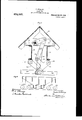
- Fig. is an elevation showing a type of car in which my invention may be embodied.
- the dump car illustrated is of a type having its Hoor composed of -downwardty and outwardly sloping sections 15. 'lhe side walls are terminated below by pendent swinging doors 16, which, when closcd, have ltheir lower edges adjacent to the lower edges of the sloping fioor 15.
- the center sill consists of two parallel channel beams 31, and it supports short, c ross l'neiubers 3Q, which'in turn support the tlo'or 15.
- I provide the following Idescrita-.d 'mechanism referring more particularly to F l, 2. 2l, and 4.
- a 'square slmftl'l'i' extends longitudinally under, the tioor being journaled in the cross members 32, and a crank 18 projects therefrom. To the end of this crank there is pivoted a crooked link '19 and at the-middle point of this crooked link 41f), there is pivoted a shorter link 20.
- These links are adapted tohlng down between the members 31 of the center sill.
- crank 1S when the doors are closed the crank 1S is practically on its dead center and thus there are two dead centers in the train of mechanism from the-shaft 17 to either door. (ln the other hand. when thel doors are in extreme open position, it. will be noted that the crank t8 has just passed its dead center with relation to the attached link 19,'and thus itwill be scelrthat the doors are locked osition. But it is obvious that rotation o the s uared shaft17 will change the mechanism rom either one of these positions to the other. Any desired means may be used for locking the squared shaft 17 in,
- a longitudinal shaft a crank rojecting therefrom, a link connected to t e end thereof, a branch link connected to an intermediate point on the aforesaid link, and operating connections from the ends of the two links to t-he respective doors on o osite sides vof, the car.
- a dump car n a dump car, a floor sloping dow'nwardly from the center to each side, pendent doors at the sides, a shaft under the center ofthe floor, mechanism directl below the shaft and connected thereto, an links from said mechanism tothe doors.
- a dumping door In a dump car, a dumping door, a center sill, a lonfritudinal shaft supportedabove the center .s1 l, and mechanism extending from said shaft down through the center sill, and thence to the said door.
- crank on said shaft,'levers pivoted to a fixed part of the car adjacent the center thereof, connections between said crank and levers, and links connecting said lcvvers with said doors, t
- a center sill comprising two longitudinal members spaced apart, a bottoni comprising sections sloping downwardly and outwardly from a'Jongitudinal line above the center sill, pendent side doors, a longitudinal operating shaft beneath said bottom and supported upon said center sill, acrank upon said shaft,
Landscapes
- Engineering & Computer Science (AREA)
- Transportation (AREA)
- Mechanical Engineering (AREA)
- Lock And Its Accessories (AREA)
- Automobile Manufacture Line, Endless Track Vehicle, Trailer (AREA)
Description
y P.V SEABERG.
DUMP GAB. APPLIUTIOIIILBD KAB. 12, 1908.
Patented 0ct.25,191o.
4 SHEETS-SHEET 1.
N sok Inventor nlneaae 77./ ffm L By F. SEABERG.
DUMP GAR.
APPLICATION FILED MAB. 12, 1908.
Patented oen. 25, 1910.
4 SHEETS-SHEET Z.
e Invani .um M
Mfnessea F. SEABERG.
DUMP GAR.
APPLICATION FILED un. 12, 190s.
l A Patented oct. 251910.
4 SHEETS-SHEET 3.
y f' @my I JZilorney-S F. SEABERG.
DUMP GAB. A APPLICATION FILED IAB.r 12, 1908.
Patented Oct. 25, 191-0.
4 SHEETS-SHEET 4.
/3' v f E Witnesses Y y Y B] Y y lofnee/S 'UNTTED STATES PATENT OFFICE.
'FREDERICK SEBERG,
l Jeu'.
-Mesfg-.exe Y or CHICAGO, ILLINOIS, Assn-Non, BY MEsNE ASSIGNMENTS, To
issNCEfi-sesf-feF-A@sesam-ries,
doors' locked in either open-or closed positiolnandwhich may he used to change thc doors" from one'of theScposi-tions lo the' other. v
These ol ject-s jparent in the following'.s pcciliralion and Fig'n'lt l iria 'cross-'stadion ot`-a dump rar hddy'emtmdyingimyiim-lworemeut. Figa -3 isa plan View ou au cillin-ged scale -of the doo1l-'.l|ol d ing.fand operating mechanism. Fig. 2l is au elevation of the sante mei-hauism. Fig. l an eli-ration corresponding toFig. l. showing thedoor holding' and op- 'criiting mechanism on :in-enlarged scale in an intermediateposition. Fig. 5 is an elevation 'of ,a modification. Fig. is an elevation showing a type of car in which my invention may be embodied.
The dump car illustrated is of a type having its Hoor composed of -downwardty and outwardly sloping sections 15. 'lhe side walls are terminated below by pendent swinging doors 16, which, when closcd, have ltheir lower edges adjacent to the lower edges of the sloping fioor 15. The center sill consists of two parallel channel beams 31, and it supports short, c ross l'neiubers 3Q, which'in turn support the tlo'or 15.
To hold and control the doors, I provide the following Idescrita-.d 'mechanism referring more particularly to F l, 2. 2l, and 4.
A 'square slmftl'l'i' extends longitudinally under, the tioor being journaled in the cross members 32, and a crank 18 projects therefrom. To the end of this crank there is pivoted a crooked link '19 and at the-middle point of this crooked link 41f), there is pivoted a shorter link 20. These links are adapted tohlng down between the members 31 of the center sill. At the fixed point 21 there l ndazff l of the .aforesaid link-20 attached-11156 theol the door 16. 'Opposite lthe 4lever 22i1istlb 60 lever :2G having a fixed fulcrum 'Qfaliti' aix otl'setf 27 which is l'iii'oted to theiaforisaid-'ti link 19. ThisI leverlt is ronnccteds-byiitlieffi l link )Hto the door. on the oppositcfsidelj ull-1li! 'lhe dooror doors-1G are h'eld aiu ol`t-"65 trolled by means of any desired nuni'hetf-"tl'f-J 'links 24. and 2h each pair being' operatedUyl i trom the squared shaft 17 by such amiehiifa msm' as hasI lbeen described. Only 'o nesuth-hv is pivoted u levcr 22 which has an oti'set 23 Y in :al p'ositioiiintermedia-te; between 'tremiyopcn and closed po'sltioiis. f
. in open mechanism is shown in the drawings,-iflvlnfilo; the vdoors are"closed` thc parts will occupy@ i'ili'tlgl@ liv 9 fi iiuit oc lt: uill he. iioted that in the closed'pos' the, lever 22 and its attached link"areth stantially in, line. that is.' th'e lerer ish dead renter. and thus the door 1G"is"lcli`\"' shut. Si'niilarlyfforthe other-door. v'ilo'ref-"U" i8 over, when the doors are closed the crank 1S is practically on its dead center and thus there are two dead centers in the train of mechanism from the-shaft 17 to either door. (ln the other hand. when thel doors are in extreme open position, it. will be noted that the crank t8 has just passed its dead center with relation to the attached link 19,'and thus itwill be scelrthat the doors are locked osition. But it is obvious that rotation o the s uared shaft17 will change the mechanism rom either one of these positions to the other. Any desired means may be used for locking the squared shaft 17 in,
essential parts o't the operati-ng i1' either of its extreme positions, but .it is .t0
observed that such locking is merely amatjtei' o f security, for none. of the load would be transmitted in any substantial degree to the lock. I have not shown mechanism for 'rotating the shaft 17 'or for locking it.` as
such mechanism is well-known and could be 5 readily7 supplled by one skilled 1n thls art. lo"
It will be seen that my door controlling v mechanism is located compactly beneath the -apex of the floor of the car` that this mechamsm comprises only a single shaft. extending lengthwise of the car, and connect-ions therefrom to the Several doors, and that the connections are of a positive character thus being distinguished from such means as chains which may be effective in one direction only.
Referring to the modification illust-rated in Fig. 5, this differs from the one previously described in thatthe link 19 is straight instead of being bent, and the oilset 23 on the lever 22 is omitted,'the link 20 being lengthened correspondingly and having its end.
to a fixed part of the car, and positive link connections from 'the shaft through said mechanism to the said doors.
2. In a dump car, pendent side doors ada ted to swing outwardly, a longitudinal sha t under the car, a crank projecting from said shaft, and door operating mechanism extending from the end of said crank to the doors on both sides of the car.
3.4 In a dump car, a longitudinal shaft, a crank rojecting therefrom, a link connected to t e end thereof, a branch link connected to an intermediate point on the aforesaid link, and operating connections from the ends of the two links to t-he respective doors on o osite sides vof, the car.
4. n a dump car, a floor sloping dow'nwardly from the center to each side, pendent doors at the sides, a shaft under the center ofthe floor, mechanism directl below the shaft and connected thereto, an links from said mechanism tothe doors.
5. In a dump car, a dumping door, a center sill, a lonfritudinal shaft supportedabove the center .s1 l, and mechanism extending from said shaft down through the center sill, and thence to the said door.
6. In a dump car, endent doors at the sides thereof, a ngitu inally disposed operating shaft adjacentthe center of the car, V
a crank on said shaft,'levers pivoted to a fixed part of the car adjacent the center thereof, connections between said crank and levers, and links connecting said lcvvers with said doors, t
7. In a dump car, a center sill comprising two longitudinal members spaced apart, a bottoni comprising sections sloping downwardly and outwardly from a'Jongitudinal line above the center sill, pendent side doors, a longitudinal operating shaft beneath said bottom and supported upon said center sill, acrank upon said shaft,
levers pivoted to said. center sill members,
links between said center sill members connectin t said levers to'said crank and links exten ing from said levers to said doors.
In testimony whereof, I, have subscribedmy name. y j
FREDERICK SEABERG. Witnesses:
ANNIE C. COURTENAY, LILmAN A. Knaur.
Priority Applications (1)
| Application Number | Priority Date | Filing Date | Title |
|---|---|---|---|
| US42064908A US974097A (en) | 1908-03-12 | 1908-03-12 | Dump-car. |
Applications Claiming Priority (1)
| Application Number | Priority Date | Filing Date | Title |
|---|---|---|---|
| US42064908A US974097A (en) | 1908-03-12 | 1908-03-12 | Dump-car. |
Publications (1)
| Publication Number | Publication Date |
|---|---|
| US974097A true US974097A (en) | 1910-10-25 |
Family
ID=3042476
Family Applications (1)
| Application Number | Title | Priority Date | Filing Date |
|---|---|---|---|
| US42064908A Expired - Lifetime US974097A (en) | 1908-03-12 | 1908-03-12 | Dump-car. |
Country Status (1)
| Country | Link |
|---|---|
| US (1) | US974097A (en) |
Cited By (4)
| Publication number | Priority date | Publication date | Assignee | Title |
|---|---|---|---|---|
| US3434433A (en) * | 1965-06-01 | 1969-03-25 | Midland Ross Corp | Hopper car door operating mechanism |
| US3608500A (en) * | 1968-09-11 | 1971-09-28 | Midland Ross Corp | Tandem toggle hopper door operating mechanism |
| US3654873A (en) * | 1970-04-20 | 1972-04-11 | Midland Ross Corp | Tandem toggle hopper door operating mechanisms |
| US4206571A (en) * | 1977-04-02 | 1980-06-10 | Waggon Union Gmbh | Bunker closure door operating mechanism |
-
1908
- 1908-03-12 US US42064908A patent/US974097A/en not_active Expired - Lifetime
Cited By (4)
| Publication number | Priority date | Publication date | Assignee | Title |
|---|---|---|---|---|
| US3434433A (en) * | 1965-06-01 | 1969-03-25 | Midland Ross Corp | Hopper car door operating mechanism |
| US3608500A (en) * | 1968-09-11 | 1971-09-28 | Midland Ross Corp | Tandem toggle hopper door operating mechanism |
| US3654873A (en) * | 1970-04-20 | 1972-04-11 | Midland Ross Corp | Tandem toggle hopper door operating mechanisms |
| US4206571A (en) * | 1977-04-02 | 1980-06-10 | Waggon Union Gmbh | Bunker closure door operating mechanism |
Similar Documents
| Publication | Publication Date | Title |
|---|---|---|
| US727487A (en) | Dumping-car. | |
| US974097A (en) | Dump-car. | |
| US693132A (en) | Car. | |
| US3227100A (en) | Hopper car door actuating mechanism | |
| US763186A (en) | Operating mechanism for dumping-cars. | |
| US3540382A (en) | Motor actuated hopper car doors | |
| US1174677A (en) | Divertible ballast-car. | |
| US1076011A (en) | Dump-car. | |
| US1155430A (en) | Door-actuating mechanism for general-service cars. | |
| US1066728A (en) | Dumping-car. | |
| US1204543A (en) | Dump-car-door-operating mechanism. | |
| US831649A (en) | Hopper-car. | |
| US524580A (en) | Dumping-car | |
| US707342A (en) | Car-door mechanism. | |
| US1125959A (en) | Combined plow, gondola, and ballast car. | |
| US992625A (en) | Dump-car. | |
| US739893A (en) | Dump-car. | |
| US995215A (en) | Dumping-car. | |
| US990030A (en) | Dump-car. | |
| US963862A (en) | Hopper dump-car. | |
| US780765A (en) | Railway-car. | |
| US420105A (en) | Dumping-car | |
| US1202481A (en) | Convertible-type dump-car. | |
| US977433A (en) | Dump-car. | |
| US767657A (en) | Dump-car. |