US9736725B2 - Method and apparatus for applying signaling of WLAN-3GPP interworking - Google Patents
Method and apparatus for applying signaling of WLAN-3GPP interworking Download PDFInfo
- Publication number
- US9736725B2 US9736725B2 US14/484,801 US201414484801A US9736725B2 US 9736725 B2 US9736725 B2 US 9736725B2 US 201414484801 A US201414484801 A US 201414484801A US 9736725 B2 US9736725 B2 US 9736725B2
- Authority
- US
- United States
- Prior art keywords
- configuration
- wlan
- interworking
- 3gpp
- communication device
- Prior art date
- Legal status (The legal status is an assumption and is not a legal conclusion. Google has not performed a legal analysis and makes no representation as to the accuracy of the status listed.)
- Active, expires
Links
Images


Classifications
-
- H—ELECTRICITY
- H04—ELECTRIC COMMUNICATION TECHNIQUE
- H04W—WIRELESS COMMUNICATION NETWORKS
- H04W28/00—Network traffic management; Network resource management
- H04W28/02—Traffic management, e.g. flow control or congestion control
- H04W28/08—Load balancing or load distribution
- H04W28/09—Management thereof
- H04W28/0925—Management thereof using policies
- H04W28/0942—Management thereof using policies based on measured or predicted load of entities- or links
-
- H—ELECTRICITY
- H04—ELECTRIC COMMUNICATION TECHNIQUE
- H04W—WIRELESS COMMUNICATION NETWORKS
- H04W28/00—Network traffic management; Network resource management
- H04W28/02—Traffic management, e.g. flow control or congestion control
- H04W28/08—Load balancing or load distribution
-
- H04W76/046—
-
- H—ELECTRICITY
- H04—ELECTRIC COMMUNICATION TECHNIQUE
- H04W—WIRELESS COMMUNICATION NETWORKS
- H04W76/00—Connection management
- H04W76/20—Manipulation of established connections
-
- H—ELECTRICITY
- H04—ELECTRIC COMMUNICATION TECHNIQUE
- H04W—WIRELESS COMMUNICATION NETWORKS
- H04W76/00—Connection management
- H04W76/20—Manipulation of established connections
- H04W76/27—Transitions between radio resource control [RRC] states
-
- H—ELECTRICITY
- H04—ELECTRIC COMMUNICATION TECHNIQUE
- H04W—WIRELESS COMMUNICATION NETWORKS
- H04W76/00—Connection management
- H04W76/30—Connection release
-
- H—ELECTRICITY
- H04—ELECTRIC COMMUNICATION TECHNIQUE
- H04W—WIRELESS COMMUNICATION NETWORKS
- H04W92/00—Interfaces specially adapted for wireless communication networks
- H04W92/02—Inter-networking arrangements
Definitions
- This disclosure generally relates to wireless communication networks, and more particularly, to a method and apparatus for applying signalling of WLAN-3GPP (Wireless Local Area Network 3 rd Generation Partnership Project) interworking.
- WLAN-3GPP Wireless Local Area Network 3 rd Generation Partnership Project
- IP Internet Protocol
- E-UTRAN Evolved Universal Terrestrial Radio Access Network
- the E-UTRAN system can provide high data throughput in order to realize the above-noted voice over IP and multimedia services.
- the E-UTRAN system's standardization work is currently being performed by the 3GPP standards organization. Accordingly, changes to the current body of 3GPP standard are currently being submitted and considered to evolve and finalize the 3GPP standard.
- a method and apparatus are disclosed for applying signaling of WLAN-3GPP interworking.
- the method includes receiving a first configuration of an interworking parameter by dedicated signalling, wherein the first configuration is not released when the UE enters idle mode.
- the method also includes receiving a second configuration of the interworking parameter by broadcast signalling when the UE is in idle mode, and overriding the first configuration with the second configuration.
- FIG. 1 shows a diagram of a wireless communication system according to one exemplary embodiment.
- FIG. 2 is a block diagram of a transmitter system (also known as access network) and a receiver system (also known as user equipment or UE) according to one exemplary embodiment.
- a transmitter system also known as access network
- a receiver system also known as user equipment or UE
- FIG. 3 is a functional block diagram of a communication system according to one exemplary embodiment.
- FIG. 4 is a functional block diagram of the program code of FIG. 3 according to one exemplary embodiment.
- FIG. 5 is a reproduction of FIG. 6.1.1.1-1 entitled “Solution 1: Traffic steering” of 3GPP TR 37.384 v0.4.0 according to one exemplary embodiment.
- FIG. 6 is a reproduction of FIG. 6.1.2.1-1 entitled “Solution 2: Traffic steering” of 3GPP TR 37.384 v0.4.0 according to one exemplary embodiment.
- FIG. 7 is a reproduction of FIG. 6.1.3.1-1 entitled “Solution 3: Traffic steering for UEs in RRC CONNECTED/CELL_DCH state” of 3GPP TR 37.384 v0.4.0 according to one exemplary embodiment.
- FIG. 8 is a flow chart according to one exemplary embodiment.
- FIG. 9 is a flow chart according to one exemplary embodiment.
- FIG. 10 is a flow chart according to one exemplary embodiment.
- FIG. 11 is a flow chart according to one exemplary embodiment.
- FIG. 12 is a flow chart according to one exemplary embodiment.
- FIG. 13 is a flow chart according to one exemplary embodiment.
- Wireless communication systems are widely deployed to provide various types of communication such as voice, data, and so on. These systems may be based on code division multiple access (CDMA), time division multiple access (TDMA), orthogonal frequency division multiple access (OFDMA), 3GPP LTE (Long Term Evolution) wireless access, 3GPP LTE-A or LTE-Advanced (Long Term Evolution Advanced), 3GPP2 UMB (Ultra Mobile Broadband), WiMax, or some other modulation techniques.
- CDMA code division multiple access
- TDMA time division multiple access
- OFDMA orthogonal frequency division multiple access
- 3GPP LTE Long Term Evolution
- 3GPP LTE-A or LTE-Advanced Long Term Evolution Advanced
- 3GPP2 UMB Ultra Mobile Broadband
- WiMax Worldwide Interoperability for Mobile communications
- the exemplary wireless communication systems devices described below may be designed to support one or more standards such as the standard offered by a consortium named “3rd Generation Partnership Project” referred to herein as 3GPP, including Document Nos. RP-122038, “New Study Item Proposal on WLAN/3GPP Radio Interworking”, Intel Corporation; TR 37.384 v0.4.0, “Study on WLAN/3GPP Radio Interworking (Release 12)”; R2-132797, “Dedicated Signaling to carry WLAN interworking Policy's assistance Information”, Broadcom Corporation; and TS 36.331 V11.4.0, “E-UTRA RRC protocol specification (Release 11)”.
- 3GPP 3rd Generation Partnership Project
- the exemplary wireless communication systems devices described below may further be designed to support IEEE 802.11 standard, “IEEE Standard for Information technology—Telecommunications and information exchange between systems Local and metropolitan area networks—Specific requirements Part 11: Wireless LAN Medium Access Control (MAC) and Physical Layer (PHY) Specifications”.
- IEEE 802.11 IEEE Standard for Information technology—Telecommunications and information exchange between systems Local and metropolitan area networks—Specific requirements Part 11: Wireless LAN Medium Access Control (MAC) and Physical Layer (PHY) Specifications”.
- MAC Wireless LAN Medium Access Control
- PHY Physical Layer
- FIG. 1 shows a multiple access wireless communication system according to one embodiment of the invention.
- An access network 100 includes multiple antenna groups, one including 104 and 106 , another including 108 and 110 , and an additional including 112 and 114 . In FIG. 1 , only two antennas are shown for each antenna group, however, more or fewer antennas may be utilized for each antenna group.
- Access terminal 116 is in communication with antennas 112 and 114 , where antennas 112 and 114 transmit information to access terminal 116 over forward link 120 and receive information from access terminal 116 over reverse link 118 .
- Access terminal (AT) 122 is in communication with antennas 106 and 108 , where antennas 106 and 108 transmit information to access terminal (AT) 122 over forward link 126 and receive information from access terminal (AT) 122 over reverse link 124 .
- communication links 118 , 120 , 124 and 126 may use different frequency for communication.
- forward link 120 may use a different frequency then that used by reverse link 118 .
- antenna groups each are designed to communicate to access terminals in a sector of the areas covered by access network 100 .
- the transmitting antennas of access network 100 may utilize beamforming in order to improve the signal-to-noise ratio of forward links for the different access terminals 116 and 122 . Also, an access network using beamforming to transmit to access terminals scattered randomly through its coverage causes less interference to access terminals in neighboring cells than an access network transmitting through a single antenna to all its access terminals.
- An access network may be a fixed station or base station used for communicating with the terminals and may also be referred to as an access point, a Node B, a base station, an enhanced base station, an eNodeB, or some other terminology.
- An access terminal may also be called user equipment (UE), a wireless communication device, terminal, access terminal or some other terminology.
- FIG. 2 is a simplified block diagram of an embodiment of a transmitter system 210 (also known as the access network) and a receiver system 250 (also known as access terminal (AT) or user equipment (UE)) in a MIMO system 200 .
- a transmitter system 210 also known as the access network
- a receiver system 250 also known as access terminal (AT) or user equipment (UE)
- traffic data for a number of data streams is provided from a data source 212 to a transmit (TX) data processor 214 .
- TX transmit
- each data stream is transmitted over a respective transmit antenna.
- TX data processor 214 formats, codes, and interleaves the traffic data for each data stream based on a particular coding scheme selected for that data stream to provide coded data.
- the coded data for each data stream may be multiplexed with pilot data using OFDM techniques.
- the pilot data is typically a known data pattern that is processed in a known manner and may be used at the receiver system to estimate the channel response.
- the multiplexed pilot and coded data for each data stream is then modulated (i.e., symbol mapped) based on a particular modulation scheme (e.g., BPSK, QPSK, M-PSK, or M-QAM) selected for that data stream to provide modulation symbols.
- the data rate, coding, and modulation for each data stream may be determined by instructions performed by processor 230 .
- TX MIMO processor 220 The modulation symbols for all data streams are then provided to a TX MIMO processor 220 , which may further process the modulation symbols (e.g., for OFDM). TX MIMO processor 220 then provides N T modulation symbol streams to N T transmitters (TMTR) 222 a through 222 t . In certain embodiments, TX MIMO processor 220 applies beamforming weights to the symbols of the data streams and to the antenna from which the symbol is being transmitted.
- Each transmitter 222 receives and processes a respective symbol stream to provide one or more analog signals, and further conditions (e.g., amplifies, filters, and upconverts) the analog signals to provide a modulated signal suitable for transmission over the MIMO channel.
- N T modulated signals from transmitters 222 a through 222 t are then transmitted from N T antennas 224 a through 224 t , respectively.
- the transmitted modulated signals are received by N R antennas 252 a through 252 r and the received signal from each antenna 252 is provided to a respective receiver (RCVR) 254 a through 254 r .
- Each receiver 254 conditions (e.g., filters, amplifies, and downconverts) a respective received signal, digitizes the conditioned signal to provide samples, and further processes the samples to provide a corresponding “received” symbol stream.
- An RX data processor 260 then receives and processes the N R received symbol streams from N R receivers 254 based on a particular receiver processing technique to provide N T “detected” symbol streams.
- the RX data processor 260 then demodulates, deinterleaves, and decodes each detected symbol stream to recover the traffic data for the data stream.
- the processing by RX data processor 260 is complementary to that performed by TX MIMO processor 220 and TX data processor 214 at transmitter system 210 .
- a processor 270 periodically determines which pre-coding matrix to use (discussed below). Processor 270 formulates a reverse link message comprising a matrix index portion and a rank value portion.
- the reverse link message may comprise various types of information regarding the communication link and/or the received data stream.
- the reverse link message is then processed by a TX data processor 238 , which also receives traffic data for a number of data streams from a data source 236 , modulated by a modulator 280 , conditioned by transmitters 254 a through 254 r , and transmitted back to transmitter system 210 .
- the modulated signals from receiver system 250 are received by antennas 224 , conditioned by receivers 222 , demodulated by a demodulator 240 , and processed by a RX data processor 242 to extract the reserve link message transmitted by the receiver system 250 .
- Processor 230 determines which pre-coding matrix to use for determining the beamforming weights then processes the extracted message.
- FIG. 3 shows an alternative simplified functional block diagram of a communication device according to one embodiment of the invention.
- the communication device 300 in a wireless communication system can be utilized for realizing the UEs (or ATs) 116 and 122 in FIG. 1 , and the wireless communications system is preferably the LTE system.
- the communication device 300 may include an input device 302 , an output device 304 , a control circuit 306 , a central processing unit (CPU) 308 , a memory 310 , a program code 312 , and a transceiver 314 .
- the control circuit 306 executes the program code 312 in the memory 310 through the CPU 308 , thereby controlling an operation of the communications device 300 .
- the communications device 300 can receive signals input by a user through the input device 302 , such as a keyboard or keypad, and can output images and sounds through the output device 304 , such as a monitor or speakers.
- the transceiver 314 is used to receive and transmit wireless signals, delivering received signals to the control circuit 306 , and outputting signals generated by the control circuit 306 wirelessly.
- FIG. 4 is a simplified block diagram of the program code 312 shown in FIG. 3 in accordance with one embodiment of the invention.
- the program code 312 includes an application layer 400 , a Layer 3 portion 402 , and a Layer 2 portion 404 , and is coupled to a Layer 1 portion 406 .
- the Layer 3 portion 402 generally performs radio resource control.
- the Layer 2 portion 404 generally performs link control.
- the Layer 1 portion 406 generally performs physical connections.
- the study item “WLAN/3GPP radio interworking” has been agreed to be studied in Release 12.
- the study item description is generally specified in 3GPP RP-122038 as follows:
- 3GPP TR 37.384 v0.4.0 captures the progress of the study.
- 3GPP TR 37.384 v0.4.0 generally specifies the assumptions, requirements, scenarios, and use cases of the study as follows:
- RAN provides RAN assistance information to the UE through broadcast signaling (and optionally dedicated signaling).
- the UE uses the RAN assistance information UE measurements and information provided by WLAN and policies that are obtained via the ANDSF or via existing OMA-DM mechanisms or pre-configured at the UE to steer traffic to WLAN or to RAN.
- This solution is applicable to UEs in RRC IDLE and RRC CONNECTED states for E-UTRAN, UE IDLE mode for UTRAN and CELL_DCH, CELL_FACH, CELL_PCH and URA_PCH states for UTRAN.
- 6.1.1.1 Description [ FIG. 5 (which is a reproduction of FIG. 6.1.1.1-1 entitled “Solution 1: Traffic steering” of 3GPP TR 37.384 v0.4.0)] illustrates solution 1 candidate call flow: RAN Assistance Information
- the following table shows candidate assistance parameters which may be provided by RAN:
- CELL_PCH and URA_PCH states the solution is similar to solution 1 or 2.
- UEs in those RRC states can be configured to connect to RAN and wait for dedicated traffic steering commands.
- User preference always takes precedence over RAN based or ANDSF based rules (e.g. when a non-operator WLAN is preferred or WLAN is off).
- the BSSID is the MAC or Probe address of the wireless access point Response SSID Service Set Identifier.
- Beacon The SSID can be used in multiple, possibly or Probe overlapping, BSSs Response HESSID Homogeneous Extended Service Set Identifier.
- Beacon A MAC address whose value shall be or Probe configured by the Hotspot Operator with Response the same value as the BSSID of one of the (802.11) APs in the network. All APs in the wireless network shall be configured with the same HESSID value.
- Domain Domain Name list element provides a list of ANQP Name List one or more domain names of the entity (HS 2.0) operating the WLAN access network. Operating Indication of the target WLAN frequency.
- N/A class See Annex E of 802.11 [5] for definitions channel of the different operating classes number
- Step 3 Traffic Steering Table 6.1.3.1-4 shows candidate examples for identifying the traffic to steer to or from WLAN.
- assistance information or parameter needs to be provided to UEs in all solutions.
- the assistance information or parameter may be used for idle mode UEs.
- the information or parameters could be provided by broadcast signaling or dedicated signaling.
- 3GPP R2-132797 addresses the following issue: which value should be applied if the value provided by broadcast signaling is different from the value provided by dedicated signaling?
- 3GPP R2-132797 proposes that when the assistance information provided in the SIB (System Information Broadcast) and in the dedicated signalling are different, the UE should use the assistance information provided in the dedicated signalling. More specifically, 3GPP R2-132797 states:
- the UE If the UE receive a different RAN assistance information values from System Information (generic values) and the dedicated RAN assistance information enabled, it should ignore the values provided in System information.
- System Information Generic values
- the dedicated RAN assistance information enabled it should ignore the values provided in System information.
- the UE When the assistance information are different between SIB and dedicated signalling, the UE should use assistance information provided in dedicated signalling.
- 3GPP TS 36.331 V11.4.0 the value provided by dedicated signalling takes precedence over the value provided by broadcast signalling for the configuration of RLF related timers and constants (such as T310, T311, N310, and/or N311). More specifically, 3GPP TS 36.331 V11.4.0 states:
- the candidates for assistance parameters may include: load information, resource allocation, WLAN threshold, and/or RAN (Radio Access Network) threshold.
- load information may include: load information, resource allocation, WLAN threshold, and/or RAN (Radio Access Network) threshold.
- WLAN threshold and RAN threshold are used to control how easily the UEs in a cell could move between WLAN and 3GPP RAN, and the setting of the thresholds may depend on the current cell load (or WLAN load if possible). If network would like a specific UE to move more easily (or less easily) than others (such as considering the UE's traffic demand), the network could give the UE a specific threshold through dedicated signalling.
- a general concept for at least one embodiment of the invention is to enable finer control to the configuration of a parameter especially for an idle mode UE.
- the value provided in the broadcast signalling could override the value provided in the dedicated signalling when the UE is in idle mode.
- the dedicated signalling would be received when the UE was in connected mode, and would still be applied in idle mode before being overridden.
- the value provided in the broadcast signalling cannot override the value provided in the dedicated signalling.
- the broadcast signalling could indicate whether it should override the value provided in the dedicated signalling (if any). The indication could be applied to a UE that is in idle mode, while not be applied to a UE in connected mode.
- a value of the parameter could be provided in the broadcast signalling, and an offset value to the parameter (which may be another parameter) could be provided in the dedicated signalling. If the value provided by the dedicated signalling is configured, the value would need to be used along with the value provided by the broadcast signalling. The two values would be coordinated so there is no issue regarding precedence or overriding. Both values could be applied to an idle mode UE (and also a connected mode UE).
- FIG. 8 is a flow chart 800 in accordance with one exemplary embodiment.
- the flow chart 800 generally illustrates a method for applying signalling of WLAN-3GPP interworking from the perspective of a UE.
- a UE receives a first configuration of an interworking parameter by dedicated signalling, wherein the first configuration is not released when the UE enters idle mode.
- the UE receives a second configuration of the interworking parameter by broadcast signalling when the UE is in idle mode.
- the UE overrides the first configuration with the second configuration. In one embodiment, the UE does not override the first configuration with the second configuration when the UE receives the second configuration in connected mode.
- the device 300 could include a program code 312 stored in memory 310 for applying signalling of WLAN-3GPP interworking from the perspective of a UE.
- the CPU 308 could execute the program code 312 to enable the UE (i) to receive a first configuration of an interworking parameter by dedicated signalling, the first configuration is not released when the UE enters idle mode, (ii) to receive a second configuration of the interworking parameter by broadcast signalling when the UE is in idle mode, and (iii) to override the first configuration with the second configuration.
- the CPU 308 could execute the program code 312 to perform all of the above-described actions and steps or others described herein.
- FIG. 9 is a flow chart 900 in accordance with one exemplary embodiment.
- the flow chart 900 generally illustrates an alternative method for applying signalling of WLAN-3GPP interworking from the perspective of a UE.
- a UE receives a second configuration of an interworking parameter by broadcast signalling.
- the broadcast signalling indicates whether the UE could use the second configuration to override a first configuration of the interworking parameter provided by a dedicated signalling.
- the device 300 could include a program code 312 stored in memory 310 for applying signalling of WLAN-3GPP interworking from the perspective of a UE.
- the CPU 308 could execute the program code 312 ( i ) to enable the UE to receive a second configuration of an interworking parameter by broadcast signalling, wherein the broadcast signalling indicates whether the UE could use the second configuration to override a first configuration of the interworking parameter provided by a dedicated signalling.
- the CPU 308 could execute the program code 312 to perform all of the above-described actions and steps or others described herein.
- FIG. 10 is a flow chart 1000 in accordance with one exemplary embodiment.
- the flow chart 1000 generally illustrates an alternative method for applying signalling of WLAN-3GPP interworking from the perspective of a network.
- the network transmits a second configuration of an interworking parameter by broadcast signalling.
- the broadcast signalling indicates whether the UE could use the second configuration to override a first configuration of the interworking parameter provided by a dedicated signalling.
- the device 300 could include a program code 312 stored in memory 310 for applying signalling of WLAN-3GPP interworking from the perspective of a network.
- the CPU 308 could execute the program code 312 ( i ) to enable a network to transmit a second configuration of an interworking parameter by broadcast signalling, wherein the broadcast signalling indicates whether the UE could use the second configuration to override a first configuration of the interworking parameter provided by a dedicated signalling.
- the CPU 308 could execute the program code 312 to perform all of the above-described actions and steps or others described herein.
- the UE could override the first configuration with the second configuration if the broadcast signalling indicates that the second configuration could override the first configuration. Furthermore, the UE would not override the first configuration with the second configuration if the broadcast signalling indicates that the second configuration could not override the first configuration. Alternatively, the UE would not override the first configuration with the second configuration if the broadcast signalling does not indicate that the second configuration could override the first configuration. In addition, the indication in broadcast signalling is used when the UE is in idle mode, or is not used when the UE is in connected mode.
- the second configuration could be used after the overriding.
- the first configuration could be applied when the UE is in idle mode, could be used before the overriding, and/or could be received by system information.
- the UE's overriding the first configuration with the second configuration comprises: (i) the UE applies the first configuration before the overriding, (ii) the UE applies the second configuration after the overriding, and (iii) the UE does not apply the first configuration after the overriding.
- the interworking parameter could be used for interworking between 3GPP and WLAN.
- the interworking parameter could be a RAN (Radio Access Network) threshold or a WLAN (Wireless Local Area Network) threshold. More specifically, the interworking parameter could be a threshold used to judge whether the UE should move its traffic to WLAN, or a threshold used to judge whether the UE should move its traffic to 3GPP RAN, such as E-UTRAN (Evolved Universal Terrestrial Radio Access Network) or UTRAN (Universal Terrestrial Radio Access Network).
- the interworking parameter could be a load information, an offload preference indicator, or a resource allocation.
- FIG. 11 is a flow chart 1100 in accordance with one exemplary embodiment.
- the flow chart 1100 generally illustrates another method for applying signalling of WLAN-3GPP interworking from the perspective of a UE.
- a UE uses a configuration of a first interworking parameter received by broadcast signalling.
- the UE uses a configuration of a second interworking parameter received by dedicated signalling, wherein the second interworking parameter is an offset value to the first interworking parameter.
- the configuration of the first interworking parameter and the configuration of the second interworking parameter are applied when the UE is in idle mode.
- the configuration of the first interworking parameter is received by system information.
- the first and the second interworking parameters could be used for interworking between a 3GPP and a WLAN.
- the first interworking parameter could be a RAN threshold or a WLAN threshold.
- the first interworking parameter could be a threshold used to judge whether the UE should move its traffic to WLAN, or a threshold used to judge whether the UE should move its traffic to a 3GPP RAN, such as a E-UTRAN or a UTRAN.
- the interworking parameter could be a load information, an offload preference indicator, or a resource allocation.
- the UE is capable of 3GPP RAN access and WLAN access. More specifically, the UE is capable of connecting to 3GPP RAN and WLAN at the same time. Furthermore, the UE operates in a WLAN when the UE is in idle mode.
- the idle mode refers to RRC_IDLE where no RRC (Radio Resource Control) connection is established, as discussed in 3GPP TS 36.331 V11.4.0.
- the connected mode refers to RRC_CONNECTED where a RRC connection is established, as discussed in 3GPP TS 36.331 V11.4.0.
- the WLAN is based on the IEEE 802.11 standard.
- the device 300 could include a program code 312 stored in memory 310 for applying signalling of WLAN-3GPP interworking from the perspective of a UE.
- the CPU 308 could execute the program code 312 to enable the UE (i) to receive a configuration of a first interworking parameter received by broadcast signalling, (ii) to receive a configuration of a second interworking parameter received by dedicated signaling, wherein the second interworking parameter is an offset value to the first interworking parameter, and (iii) to apply the configuration of the first interworking parameter and the configuration of the second interworking parameter when the UE is in idle mode.
- the CPU 308 could execute the program code 312 to perform all of the above-described actions and steps or others described herein.
- a timer could be utilized to control the validity of the configured value provided in the dedicated signalling for the interworking parameter.
- a UE would release the configured value provided in the dedicated signalling and would use the value provided in the broadcast signalling when the timer expires. More specifically, the UE would be in idle mode when the timer expires.
- the value of the timer could be signalled along with the value of the interworking parameter.
- the value of the timer could be signalled in the message to release the RRC (Radio Resource Control) connection of the UE, or signalled in the system information, or predefined in the 3GPP standards. The timer could be started upon receiving the dedicated configuration or upon entering idle mode.
- RRC Radio Resource Control
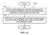
- FIG. 12 is a flow chart 1200 in accordance with one exemplary embodiment.
- the flow chart 1200 generally illustrates another method for applying signalling of WLAN-3GPP interworking from the perspective of a UE.
- the UE uses a first configuration of an interworking parameter received by dedicated signalling, wherein the first configuration is applicable in a connected mode and an idle mode.
- the UE uses a second configuration of the interworking parameter received by broadcast signalling when a timer associated with the first configuration expires.
- the device 300 could include a program code 312 stored in memory 310 for applying signalling of WLAN-3GPP interworking from the perspective of a UE.
- the CPU 308 could execute the program code 312 to enable the UE (i) to use a first configuration of an interworking parameter received by dedicated signalling, wherein the first configuration is applicable in a connected mode and an idle mode, and (ii) to uses a second configuration of the interworking parameter received by broadcast signalling when a timer associated with the first configuration expires.
- the CPU 308 could execute the program code 312 to perform all of the above-described actions and steps or others described herein.
- FIG. 13 is a flow chart 1300 in accordance with one exemplary embodiment.
- the flow chart 1300 generally illustrates another method for applying signalling of WLAN-3GPP interworking from the perspective of a UE.
- the UE uses a first configuration of an interworking parameter received by dedicated signalling in connected mode.
- the UE enters an idle mode and starts a timer associated with the first configuration.
- the UE uses a second configuration of the interworking parameter received from broadcast signalling when the timer associated with the first configuration expires.
- the device 300 could include a program code 312 stored in memory 310 for applying signalling of WLAN-3GPP interworking from the perspective of a UE.
- the CPU 308 could execute the program code 312 to enable the UE (i) to use a first configuration of an interworking parameter received by dedicated signalling, wherein the first configuration is applicable in a connected mode and an idle mode, (ii) to enter an idle mode and starts a timer associated with the first configuration, and (iii) to use a second configuration of the interworking parameter received by broadcast signalling when the timer associated with the first configuration expires.
- the CPU 308 could execute the program code 312 to perform all of the above-described actions and steps or others described herein.
- the UE overrides the first configuration with the second configuration when the timer expires.
- the UE releases the first configuration when the timer expires.
- the UE is in idle mode when the timer expires.
- the second configuration does not override the first configuration when the UE is in connected mode.
- the UE is capable of 3GPP RAN access and WLAN access. More specifically, the UE is capable of connecting to a 3GPP RAN and a WLAN at the same time. Also, the UE operates in a WLAN when the UE is in idle mode.
- the idle mode refers to RRC_IDLE where no RRC (Radio Resource Control) connection is established, as discussed in 3GPP TS 36.331 V11.4.0.
- the connected mode refers to RRC_CONNECTED where a RRC connection is established, as discussed in 3GPP TS 36.331 V11.4.0.
- the WLAN is based on the IEEE 802.11 standard.
- the timer could be started when the UE receives the first configuration, when the UE receives the configuration of the timer, or when the UE enters idle mode.
- the configuration of the timer could be received along with the first configuration, or could be received in the message to release the RRC connection of the UE.
- the value of the timer could be broadcasted in a system information, or could be predefined.
- the interworking parameter could be used for interworking between 3GPP and WLAN.
- the interworking parameter could be a RAN (Radio Access Network) threshold or a WLAN (Wireless Local Area Network) threshold. More specifically, the interworking parameter could be a threshold used to judge whether the UE should move its traffic to WLAN, or a threshold used to judge whether the UE should move its traffic to a 3GPP RAN, such as a E-UTRAN or a UTRAN.
- the interworking parameter could be a load information, an offload preference indicator, or a resource allocation.
- finer control can be enabled for an idle mode UE which has already been configured with dedicated value of an interworking parameter.
- an idle mode UE which has already been configured with dedicated value of an interworking parameter can be updated with the latest value.
- concurrent channels may be established based on pulse repetition frequencies.
- concurrent channels may be established based on pulse position or offsets.
- concurrent channels may be established based on time hopping sequences.
- concurrent channels may be established based on pulse repetition frequencies, pulse positions or offsets, and time hopping sequences.
- the various illustrative logical blocks, modules, and circuits described in connection with the aspects disclosed herein may be implemented within or performed by an integrated circuit (“IC”), an access terminal, or an access point.
- the IC may comprise a general purpose processor, a digital signal processor (DSP), an application specific integrated circuit (ASIC), a field programmable gate array (FPGA) or other programmable logic device, discrete gate or transistor logic, discrete hardware components, electrical components, optical components, mechanical components, or any combination thereof designed to perform the functions described herein, and may execute codes or instructions that reside within the IC, outside of the IC, or both.
- a general purpose processor may be a microprocessor, but in the alternative, the processor may be any conventional processor, controller, microcontroller, or state machine.
- a processor may also be implemented as a combination of computing devices, e.g., a combination of a DSP and a microprocessor, a plurality of microprocessors, one or more microprocessors in conjunction with a DSP core, or any other such configuration.
- a software module e.g., including executable instructions and related data
- other data may reside in a data memory such as RAM memory, flash memory, ROM memory, EPROM memory, EEPROM memory, registers, a hard disk, a removable disk, a CD-ROM, or any other form of computer-readable storage medium known in the art.
- a sample storage medium may be coupled to a machine such as, for example, a computer/processor (which may be referred to herein, for convenience, as a “processor”) such the processor can read information (e.g., code) from and write information to the storage medium.
- a sample storage medium may be integral to the processor.
- the processor and the storage medium may reside in an ASIC.
- the ASIC may reside in user equipment.
- the processor and the storage medium may reside as discrete components in user equipment.
- any suitable computer-program product may comprise a computer-readable medium comprising codes relating to one or more of the aspects of the disclosure.
- a computer program product may comprise packaging materials.
Landscapes
- Engineering & Computer Science (AREA)
- Computer Networks & Wireless Communication (AREA)
- Signal Processing (AREA)
- Mobile Radio Communication Systems (AREA)
Priority Applications (1)
| Application Number | Priority Date | Filing Date | Title |
|---|---|---|---|
| US14/484,801 US9736725B2 (en) | 2013-09-16 | 2014-09-12 | Method and apparatus for applying signaling of WLAN-3GPP interworking |
Applications Claiming Priority (3)
| Application Number | Priority Date | Filing Date | Title |
|---|---|---|---|
| US201361878221P | 2013-09-16 | 2013-09-16 | |
| US201361887600P | 2013-10-07 | 2013-10-07 | |
| US14/484,801 US9736725B2 (en) | 2013-09-16 | 2014-09-12 | Method and apparatus for applying signaling of WLAN-3GPP interworking |
Publications (2)
| Publication Number | Publication Date |
|---|---|
| US20150078153A1 US20150078153A1 (en) | 2015-03-19 |
| US9736725B2 true US9736725B2 (en) | 2017-08-15 |
Family
ID=51542210
Family Applications (1)
| Application Number | Title | Priority Date | Filing Date |
|---|---|---|---|
| US14/484,801 Active 2034-12-17 US9736725B2 (en) | 2013-09-16 | 2014-09-12 | Method and apparatus for applying signaling of WLAN-3GPP interworking |
Country Status (8)
| Country | Link |
|---|---|
| US (1) | US9736725B2 (ko) |
| EP (1) | EP2849486B1 (ko) |
| JP (1) | JP6351457B2 (ko) |
| KR (1) | KR101715316B1 (ko) |
| CN (1) | CN104469856B (ko) |
| ES (1) | ES2693466T3 (ko) |
| PL (1) | PL2849486T3 (ko) |
| TW (1) | TWI571160B (ko) |
Cited By (1)
| Publication number | Priority date | Publication date | Assignee | Title |
|---|---|---|---|---|
| US10542513B2 (en) | 2017-11-21 | 2020-01-21 | Electronics And Telecommunications Research Institute | Deregistration method of user equipment in network and user equipment performing the same |
Families Citing this family (22)
| Publication number | Priority date | Publication date | Assignee | Title |
|---|---|---|---|---|
| KR101715316B1 (ko) * | 2013-09-16 | 2017-03-10 | 이노베이티브 소닉 코포레이션 | Wlan3gpp 인터워킹의 시그널링을 적용하는 방법 및 장치 |
| US20160057677A1 (en) * | 2014-02-21 | 2016-02-25 | Telefonaktiebolaget L M Ericsson (Publ) | Traffic Steering in a WLAN Based on Transmit Power Control |
| CN106031242B (zh) * | 2014-03-17 | 2019-10-18 | Lg电子株式会社 | 在无线通信系统中处理用于小区改变的ran协助信息的方法和装置 |
| WO2015174757A1 (en) | 2014-05-16 | 2015-11-19 | Lg Electronics Inc. | Method and apparatus for handling ran assistance information for radio link failure in wireless communication system |
| US20160255534A1 (en) * | 2014-05-19 | 2016-09-01 | Telefonaktiebolaget L M Ericsson (Publ) | Techniques for Managing Parameters Used by Terminal Devices in Access Network Selection and/or Traffic Steering or Routing Procedures |
| CN107079379B (zh) | 2014-08-18 | 2021-10-12 | Oppo广东移动通信有限公司 | 用于控制终端设备的操作的方法和装置 |
| EP3266247B1 (en) * | 2015-03-03 | 2020-01-15 | Telefonaktiebolaget LM Ericsson (publ) | Traffic steering between wireless access networks |
| WO2016154106A1 (en) * | 2015-03-20 | 2016-09-29 | Nokia Technologies Oy | Optimized signaling for wlan/3gpp aggregation |
| EP3079399B1 (en) * | 2015-04-10 | 2017-12-13 | HTC Corporation | Device and method of handling offload parameter according to cell selection |
| US9900911B2 (en) * | 2015-05-15 | 2018-02-20 | Mediatek Inc. | QoS provisioning for LTE-WLAN aggregation |
| CN107810653B (zh) * | 2015-06-22 | 2021-09-14 | 三星电子株式会社 | Ue、蜂窝基站以及通过其各自执行通信的方法 |
| WO2017018539A1 (ja) * | 2015-07-30 | 2017-02-02 | 京セラ株式会社 | 基地局及び無線端末 |
| EP3354058B1 (en) * | 2015-09-24 | 2022-02-16 | Nokia Technologies Oy | Method of ue autonomous measurement related actions upon implicit triggers |
| EP3343977A4 (en) * | 2015-09-25 | 2018-09-05 | Huawei Technologies Co., Ltd. | Method and device for interoperation between networks |
| WO2017061724A1 (ko) * | 2015-10-08 | 2017-04-13 | 엘지전자 주식회사 | 단말이 트래픽 조종을 수행하는 방법 및 장치 |
| EP3169120B1 (en) | 2015-11-10 | 2020-03-04 | Alcatel Lucent | Support of wlan location change reporting or retrieval for untrusted wlan access to a 3gpp packet core network |
| US11096106B2 (en) * | 2016-02-02 | 2021-08-17 | Motorola Mobility Llc | Rules handling in a wireless communication system |
| US10021617B2 (en) * | 2016-04-01 | 2018-07-10 | Lg Electronics Inc. | Method and apparatus for performing, by terminal in WLAN interworking operation, handover |
| WO2017171475A1 (en) | 2016-04-01 | 2017-10-05 | Samsung Electronics Co., Ltd. | Method and apparatus for wireless communication in wireless communication system |
| US10820370B2 (en) | 2016-05-18 | 2020-10-27 | Samsung Electronics Co., Ltd. | Method and apparatus for performing efficient layer 2 function in mobile communication system |
| CN109792395B (zh) * | 2016-09-30 | 2021-11-12 | 瑞典爱立信有限公司 | 用于广播信令传输的方法和设备 |
| WO2021203387A1 (zh) * | 2020-04-09 | 2021-10-14 | Oppo广东移动通信有限公司 | 一种配置信息的确定方法及装置、终端设备 |
Citations (6)
| Publication number | Priority date | Publication date | Assignee | Title |
|---|---|---|---|---|
| US20120324100A1 (en) * | 2011-04-13 | 2012-12-20 | Interdigital Patent Holdings, Inc | Methods, systems and apparatus for managing and/or enforcing policies for managing internet protocol ("ip") traffic among multiple accesses of a network |
| US20120329402A1 (en) * | 2010-06-13 | 2012-12-27 | Zte Corporation | Method for controlling drive test logged measurement, drive test system and user equipment |
| US20130122892A1 (en) * | 2010-06-24 | 2013-05-16 | Ntt Docomo, Inc. | Mobile communication method and relay node |
| US20150078153A1 (en) * | 2013-09-16 | 2015-03-19 | Innovative Sonic Corporation | Method and apparatus for applying signaling of wlan-3gpp interworking |
| US20150249900A1 (en) * | 2012-09-26 | 2015-09-03 | Lg Electronics Inc. | Mtc monitoring method |
| US20150358884A1 (en) * | 2013-01-18 | 2015-12-10 | Kyocera Corporation | Communication control method and user terminal |
Family Cites Families (4)
| Publication number | Priority date | Publication date | Assignee | Title |
|---|---|---|---|---|
| WO2008156266A1 (en) * | 2007-06-19 | 2008-12-24 | Lg Electronics Inc. | Conditional procedure handling in a wireless communication system |
| JP5042104B2 (ja) * | 2007-12-27 | 2012-10-03 | パナソニック株式会社 | 通信システム、端末装置、基地局、通信品質管理方法およびプログラム |
| WO2012149954A1 (en) * | 2011-05-03 | 2012-11-08 | Nokia Siemens Networks Oy | Traffic offload in communication networks |
| WO2014168427A1 (en) * | 2013-04-12 | 2014-10-16 | Lg Electronics Inc. | Method and apparatus for applying assistance information for traffic steering in wireless communication system |
-
2014
- 2014-09-11 KR KR1020140120170A patent/KR101715316B1/ko active IP Right Grant
- 2014-09-12 JP JP2014185946A patent/JP6351457B2/ja active Active
- 2014-09-12 US US14/484,801 patent/US9736725B2/en active Active
- 2014-09-15 ES ES14184755.8T patent/ES2693466T3/es active Active
- 2014-09-15 TW TW103131725A patent/TWI571160B/zh active
- 2014-09-15 PL PL14184755T patent/PL2849486T3/pl unknown
- 2014-09-15 EP EP14184755.8A patent/EP2849486B1/en active Active
- 2014-09-16 CN CN201410471763.4A patent/CN104469856B/zh active Active
Patent Citations (6)
| Publication number | Priority date | Publication date | Assignee | Title |
|---|---|---|---|---|
| US20120329402A1 (en) * | 2010-06-13 | 2012-12-27 | Zte Corporation | Method for controlling drive test logged measurement, drive test system and user equipment |
| US20130122892A1 (en) * | 2010-06-24 | 2013-05-16 | Ntt Docomo, Inc. | Mobile communication method and relay node |
| US20120324100A1 (en) * | 2011-04-13 | 2012-12-20 | Interdigital Patent Holdings, Inc | Methods, systems and apparatus for managing and/or enforcing policies for managing internet protocol ("ip") traffic among multiple accesses of a network |
| US20150249900A1 (en) * | 2012-09-26 | 2015-09-03 | Lg Electronics Inc. | Mtc monitoring method |
| US20150358884A1 (en) * | 2013-01-18 | 2015-12-10 | Kyocera Corporation | Communication control method and user terminal |
| US20150078153A1 (en) * | 2013-09-16 | 2015-03-19 | Innovative Sonic Corporation | Method and apparatus for applying signaling of wlan-3gpp interworking |
Non-Patent Citations (5)
| Title |
|---|
| 3GPP TR 37.834 V0.4.0 (Aug. 2013). |
| 3GPP TSG-RAN WG2 #83, Barcelona, Aug. 19-23, 2013 (R2-132649). |
| 3GPP TSG-RAN WG2 Meeting #83, Barcelona, Spain, Aug. 19-23, 2013 (R2-132327). |
| Office Action on corresponding JP Patent Application No. 2014-185946 dated Sep. 29, 2015. |
| Search Report on corresponding EP Patent Application No. 14184755.8 dated May 8, 2015. |
Cited By (2)
| Publication number | Priority date | Publication date | Assignee | Title |
|---|---|---|---|---|
| US10542513B2 (en) | 2017-11-21 | 2020-01-21 | Electronics And Telecommunications Research Institute | Deregistration method of user equipment in network and user equipment performing the same |
| US10638443B2 (en) | 2017-11-21 | 2020-04-28 | Electronics And Telecommunications Research Institute | Deregistration method of user equipment in network and user equipment performing the same |
Also Published As
| Publication number | Publication date |
|---|---|
| EP2849486A3 (en) | 2015-06-03 |
| JP6351457B2 (ja) | 2018-07-04 |
| TWI571160B (zh) | 2017-02-11 |
| PL2849486T3 (pl) | 2018-11-30 |
| CN104469856B (zh) | 2019-04-09 |
| EP2849486A2 (en) | 2015-03-18 |
| US20150078153A1 (en) | 2015-03-19 |
| TW201513714A (zh) | 2015-04-01 |
| KR20150032177A (ko) | 2015-03-25 |
| JP2015057883A (ja) | 2015-03-26 |
| ES2693466T3 (es) | 2018-12-11 |
| KR101715316B1 (ko) | 2017-03-10 |
| CN104469856A (zh) | 2015-03-25 |
| EP2849486B1 (en) | 2018-08-01 |
Similar Documents
| Publication | Publication Date | Title |
|---|---|---|
| US9736725B2 (en) | Method and apparatus for applying signaling of WLAN-3GPP interworking | |
| US10194357B2 (en) | Method and apparatus for applying assistance information for traffic steering in wireless communication system | |
| CN112312503B (zh) | 具有lte-wlan聚合的网络选择及数据聚合 | |
| US10178609B2 (en) | System and method to support inter-wireless local area network communication by a radio access network | |
| EP2965556B1 (en) | Method and apparatus for handling traffic steering failure in wireless communication system | |
| US9769693B2 (en) | Method and apparatus of improving measurement reporting involving WLAN in a wireless communication system | |
| EP2946599A1 (en) | Enhanced integration between wi-fi and mobile communication networks | |
| US11191015B2 (en) | Efficient communication of network identifiers | |
| US10694568B2 (en) | Efficient communication of network identifiers |
Legal Events
| Date | Code | Title | Description |
|---|---|---|---|
| AS | Assignment |
Owner name: INNOVATIVE SONIC CORPORATION, TAIWAN Free format text: ASSIGNMENT OF ASSIGNORS INTEREST;ASSIGNORS:KUO, RICHARD LEE-CHEE;OU, MENG-HUI;REEL/FRAME:033730/0787 Effective date: 20140826 |
|
| STCF | Information on status: patent grant |
Free format text: PATENTED CASE |
|
| MAFP | Maintenance fee payment |
Free format text: PAYMENT OF MAINTENANCE FEE, 4TH YEAR, LARGE ENTITY (ORIGINAL EVENT CODE: M1551); ENTITY STATUS OF PATENT OWNER: LARGE ENTITY Year of fee payment: 4 |